DG Interconnection Workshop - National Grid plc · DG Interconnection Workshop (CHP Focus) ......
94
DG Interconnection Workshop (CHP Focus) April 24, 2014 National Grid Office 939 Southbridge St, Worcester, MA 01610 Auditorium
Transcript of DG Interconnection Workshop - National Grid plc · DG Interconnection Workshop (CHP Focus) ......

DG Interconnection Workshop(CHP Focus)
April 24, 2014
National Grid Office
939 Southbridge St, Worcester, MA 01610
Auditorium
2
AGENDA
Co-Hosts

Agenda
3
8:30 Registration and Continental Breakfast9:00 Welcome, Opening Remarks – Kevin Kelly9:15 CHP Incentive Program & Process – Mark DiPetrillo9:45 Interconnection Process & Timing – John Rathbun10:35 Interconnection Developments – Tim Roughan 11:00 Break11:05 Interconnection Technical Session: – James Cleary12:00 Questions and Answer Session - National Grid Panel 12:30 Adjourn

4
Safety Moment
� Overhead power lines are not insulated, and carry enough energy to cause serious injury or even death. Regard all wires as live.
� Keep yourself, your co-workers, tools, and vehicles at least 10 feet away from electric lines and equipment.
� Stay alert. Keep ladders at least 10 feet away from power lines when carrying, moving, and raising them.
� Make sure the area is clear of wires before working near trees or shrubs.
� Never attach or tie anything off to power lines or electrical equipment.� If you need to dig, first call Dig Safe at 1-888-dig-safe (1-888-344-
7233) to get underground utilities marked.

5
Logistics & Introductions
� Facilities
�Emergency Exits
�Restrooms
�Designated smoking areas
�Mobile Phones
� Introductions
�DOER / Mass CEC
�MA Utilities
�Guests

6
DOER Welcome Slide
DOER’s role in Distributed Generation:
o Assisting with incentives for clean energy
• Portfolio Standards (RPS/SRECs/APS)
• Net Metering
o Increasing awareness about policies
• Interconnection
• Rates
• System Planning / Service Quality
o Advising on new policies
• Streamlining Interconnection
• Hands-on assistance with challenging projects

Mark DiPetrilloManager, Technical Services – New [email protected]
Utility Incentives for Combined Heat and Power (CHP)
7

MA-RI Gas and Electric Service Territory
8

MA ‘new’ Incentives: Summary
Tier 1 Tier 2 Tier 3
Basic Moderate Advanced
---
$750 per kW
Up to $950 per kW for
units > 150 kW or
Up to $1,000 per kW for
units <= 150 kW
Up to $1,100 per kW for
units > 150 kW or
Up to $1,200 per kW for
units <= 150 kW
---Annual estimated
efficiency > 60%
Annual estimated
efficiency > 65%
Requires implementation
of EE measures
Requires implementation
of EE measures
--- ---Total site energy use to
be reduced by > 10%
Identify EE opportunities
prior to sizing CHP
system
ASHRAE Level 1 audit
required
ASHRAE Level 2 audit
required
9

Requirements for all Tiers
� Pass the Massachusetts Program Administrators’ Benefit/Cost Test requirements
� 60% Combined electric and thermal efficiency (HHV basis) is highly desirable in MA� A project which barely exceeds the minimum efficiency
requirement is less likely to have a BCR > 1.0� Right-sizing is important! CHP sizing should take EE measures in
consideration� Max Incentive up to 50% of Installed Cost
� Incentive offered will consider overall added value of the CHP project to the EE portfolio; such as, overall building energy efficiency, BCR ratio and project risk.
� Incentives subject to PA Budget Limitations
10

Tier 1 Details
� Systems smaller than 150 kW: $750 per kW
� Over 150 kW: Up to $750 per kW
Requirements
� Identify EE Measures
� Correctly sized CHP based on thermal and electrical loads
11

Tier 2 Details
� Systems smaller than 150 kW: Up to $1000 per kW
� Over 150 kW: Up to $950 per kW
Requirements
� Identify EE Measures using ASHRAE Level 1 Audit
� Annual Efficiency > 60%
� Correctly sized CHP based on thermal and electrical loads assuming that EE measures with less than 3 year payback will be implemented
� Agree to implement EE measures within 18 months
12

Tier 2 Payment
� 80% of Tier 1 upon completion as per MRD
� 20% of Tier 1 upon commissioning as per MRD
� Remaining tier 2 incentive upon completion of EE measures per their own MRD
13

Tier 3 Details
� Systems smaller than 150 kW: Up to $1200 per kW
� Over 150 kW: Up to $1100 per kW
Requirements
� Identify EE Measures using ASHRAE Level 2 Audit
� Annual Efficiency > 65%
� Reduce site energy use >10% within 3 years
� Correctly sized CHP based on thermal and electrical loads assuming that EE measures with less than 3 year payback will be implemented
� Agree to implement EE measures within 18 months
14

Tier 3 Payment
� 80% of Tier 1 upon completion as per MRD
� 20% of Tier 1 upon commissioning as per MRD
� Remaining tier 3 incentive upon completion of EE measures per MRD and demonstration of 10% energy use reduction for the facility
15

Rhode Island CHP Requirements
� Project qualifies for incentive if passes BCR test and CHP is:
�Thermal Leading and correctly sized
orororor
�Uses waste heat/energy to generate electricity
� Project must have annual efficiency > 55% Combined Electric and
Thermal Efficiency (HHV basis)
16

RI Incentive Levels
� $900/Net kW for Annual efficiency >55% and <60%
� $1000/Net kW for Annual efficiency >60%
� If reduce the site energy use at least 5% or identified by TA study –
1) $1125/kW for projects with annual efficiency >55% to 60%
2) $1250/kW for projects with annual efficiency >60%
(Thermal Load following facility will have reduce 5% of thermal energy use. Electric Load following system will have to reduce 5% of the electrical energy use)
� Commitments made for energy efficiency projects in last 5 Years can be counted towards 5%
17

RI Incentive Levels (cont.)
� All CHP projects can receive Advance gas technology (AGT) incentive (If margin isn’t eating up by service upgrades)
� Projects > 1MW – There may be a performance based additional incentive up to $20/kW-Yr subjected to max incentive limit of 70%
� All incentives will not exceed 70% of the installed cost
� 20% of the incentive will be held until commissioning is completed
� MRD governs the scope, commissioning, and M&V requirements
18

RI - Incentive Payment
� Following installation, 80% payment is made for installations which are in compliance with pre-approval terms.
� Remaining 20% is released following completion of commissioning and analysis of metered data.
19

CHP Tariff Consideration- RI
Customers must agree to pay greater of
�Demand and energy charges under the general service (greater of 100% of the demand in the current month or 75% of the max demand in the last 11 months)
or
�A minimum charge based on 50% of the demand charge based on customer’s max generation during the peak period plus the delivered load charges plus the monthly customer charge
To receive CHP rebates on larger rates.
20

Primary BCR Drivers
� Benefit/Cost Ratio Benefit/Cost Ratio Benefit/Cost Ratio Benefit/Cost Ratio testtesttesttest
� Installed Cost of CHP and auxiliaries (including interconnection Installed Cost of CHP and auxiliaries (including interconnection Installed Cost of CHP and auxiliaries (including interconnection Installed Cost of CHP and auxiliaries (including interconnection and meter costs)and meter costs)and meter costs)and meter costs)
� kWh and heat utilization, kW generated during the super peak kWh and heat utilization, kW generated during the super peak kWh and heat utilization, kW generated during the super peak kWh and heat utilization, kW generated during the super peak periodperiodperiodperiod
� Run HoursRun HoursRun HoursRun Hours
� Incremental fuel usageIncremental fuel usageIncremental fuel usageIncremental fuel usage
� On site use of thermal energyOn site use of thermal energyOn site use of thermal energyOn site use of thermal energy
� Maintenance CostsMaintenance CostsMaintenance CostsMaintenance Costs
� Avoided Costs of generation/transmission/distributionAvoided Costs of generation/transmission/distributionAvoided Costs of generation/transmission/distributionAvoided Costs of generation/transmission/distribution
21

Other Requirements
� Interconnection Application Approval
�Start ASAP
�Follow the procedure, (Go to Electric Utility website)
� Air Emissions Permits
� Local and State Construction Permits
� APS Credit Application with DOER ( optional)
� Any Federal grant $s should be deducted from the estimated cost
22

Factors to Consider
� Interconnection requirements and schedule, Island Mode
Operation
� Gas availability/cost
� Right sizing the CHP unit
� Customer’s ability to operate and maintain
� Ability to manage the project implementation
23
Summary
� CHP can be a good energy savings opportunity for certain customers
� Implement or consider other EE measures before sizing the unit
� Careful analysis is necessary to ensure the facility’s thermal and electric needs and profile are consistent with CHP equipment selection and economic viability
� System needs to be properly controlled to minimize thermal dumping and exporting of power
� Obtain early involvement of Program Administrator!Obtain early involvement of Program Administrator!Obtain early involvement of Program Administrator!Obtain early involvement of Program Administrator!
24

ERV Basics
DG Interconnect Process (CHP Focus)
John Rathbun Technical Sales Engineering Support

Interconnect Discussion Agenda
� The purpose of the Interconnect Process
� Interconnection Process
�Steps
�Costs
�Timetable
� kWh export and Synchronous parallel
� Contacts and links to further information
� Technical Discussion
26

27
DG Activity Trends - NE
� Received 857 interconnection applications worth about 70 MW of interconnection applications through March of 2014 and 499 apps through March of 2013.
� Small (<100kW) Interconnection application are triggering large studies because of the aggregate generation on the circuit.
� Some circuits have over 20 interconnected generators

28
DG Activity Trends - NE
� Interconnected over 600 applications worth about 16 MW through March 2014
� Interconnected over 500 applications worth about 10 MW through March 2013

29
DG Activity Trends - MA
� Received 844 applications worth almost 68 MW of interconnection applications through March 2014
� Received 466 applications worth almost 60 MW of interconnection applications through March 2013

30
DG Activity Trends - MA
� Interconnected almost 600 applications worth about 12 MW through March 2014
� Interconnected almost 500 applications worth about 8 MW through March 2013

Importance of the Interconnection Process
� Following the interconnection process is important because a DG system can present dangers to utility workers if proper equipment is not installed
� While robust and capable of handling minor disturbances, the quality of grid power is extremely important. The interconnection process ensures the DG meets safety, reliability, & power quality requirements with regard to:
Islanding
Transient Voltage Conditions
Noise and Harmonics
Frequency
Voltage Level
Machine Reactive Capability
� It is essential that each DG customer receive an interconnection agreement with the utility before installing any generation. You are proceeding at your own risk if you choose to install a system without utility approval.
31

Interconnect Process Steps
� Pre-application
� Simplified and Expedited Application
� Standard Application
� Impact Study and Detailed Study
� Conditional approval
� Construction
� Witness Test
� Authorization to Interconnect
https://www.nationalgridus.com/masselectric/home/energyeff/4_interconnection-process.asp
http://ngridustest/narragansett/home/energyeff/4_interconnection-process.asp
32

Pre-Application Report
Customer needs to provide:
Contact Person; Mailing Address; Telephone; E-Mail Address
Alternative Contact Information (e.g., system installation contractor or coordinating Facility Information:
Proposed Facility Location (street address with cross streets, including town, and a Google Map still picture and GPS coordinates):
Generation Type: Size (AC kW): Single or Three Phase
Generator Configuration:
Stand-alone (no on-site load, not including parasitic load)?
If there is existing service at the Proposed Facility site, provide: Interconnecting Customer Account Number
Site minimum and maximum (if available) current or proposed electric loads:
Is new service or service upgrade needed?
Utility to provide:
Circuit voltage at the substation;Circuit name;Circuit voltage at proposed Facility;Whether Single or three phase is available near site; If single phase – distance from three phase service;Aggregate connected Facilities (kW) on circuit;Submitted complete applications of Facilities (kW) on circuit that have not yet been interconnected;Whether the Interconnecting Customer is served by an area network, a spot network, or radial system;Identification of feeders within ¼ mile of the proposed interconnection site through a snap-shot of GIS map or other means; Other potential system constraints or critical items that may impact the proposed Facility.
33

Everything starts with the Application
� A complete complex application package includes:
All appropriate sections of 4-page application completely filled out.
Copy of Pre-Application Report
Application fee $4.50/KW ($300 minimum and $7,500 maximum). This fee covers the initial review.
Stamped electric one-line diagram, preferably showing relay controls (one copy)
Site diagram (one copy)
One copy of any supplemental information (if electronic – single copy acceptable)
Identify electric customer and owner of proposed generation
� Errors or problems with application will slow down the process and “stop the clock”
� Send Electronic copy of all documents preferred if possible – Easier to distribute, saves paper, and is faster. However, submit first page of application with application fee.
34

Simplified Review Path
� Applies to:
� Single phase customers with Listed single-phase inverter based systems 15kW (was previously 10 kW) or less on a single phase service on a radial feed
� Three phase customers with listed three-phase inverter based systems 25kW or less on a three phase service on a radial feed.
� Listed inverters:
� Comply with current IEEE 1547 Standards
� Have nationally recognized test lab results
� Does allow an increase in time for review if screen 5 is not met
� Proposed project is not compatible with the existing service at the site, e.g. loading on existing service transformer, etc.
� 20 days versus 15 for the review of screens
� Does not Apply to:
� Non-listed inverters or other generators (induction / synchronous / asynchronous)
� Aggregate generation capacity of listed inverters that exceed the above-mentioned limits
35
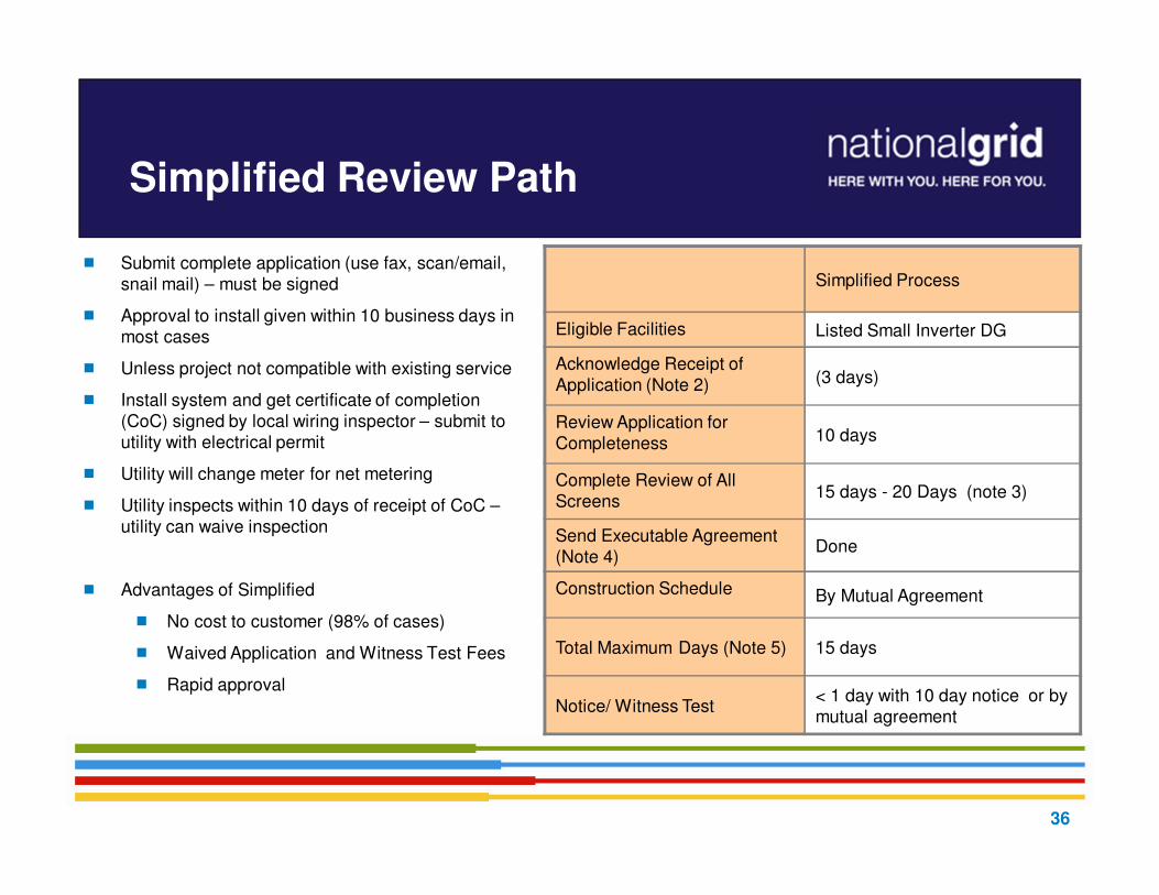
Simplified Review Path
� Submit complete application (use fax, scan/email, snail mail) – must be signed
� Approval to install given within 10 business days in most cases
� Unless project not compatible with existing service
� Install system and get certificate of completion (CoC) signed by local wiring inspector – submit to utility with electrical permit
� Utility will change meter for net metering
� Utility inspects within 10 days of receipt of CoC –utility can waive inspection
� Advantages of Simplified
� No cost to customer (98% of cases)
� Waived Application and Witness Test Fees
� Rapid approval
Simplified Process
Eligible Facilities Listed Small Inverter DG
Acknowledge Receipt of Application (Note 2) (3 days)
Review Application for Completeness 10 days
Complete Review of All Screens
15 days - 20 Days (note 3)
Send Executable Agreement (Note 4)
Done
Construction Schedule By Mutual Agreement
Total Maximum Days (Note 5) 15 days
Notice/ Witness Test< 1 day with 10 day notice or by mutual agreement
36

Expedited Review Path
� Applies to:
Single phase customers with listed single-phase inverter based systems >15 kW on a radial feed
Three phase customers with listed three-phase inverter based systems >25kW on a radial feed.
Maximum size is based on review of screens
� Does not Apply to:
Non-listed inverters or other generators (induction / synchronous / asynchronous)
Aggregate generation capacity of listed inverters that exceed the above-mentioned limits
37

Expedited Review Path
� Typically little or no (utility) system modifications required. If meter only – usually no charges passed to customer
� Application fee plus any Supplemental Review charges up to 30 hours of engineering time @ $150/hr (if needed)
� Relay control system must be well defined to make supplemental review easier.
� Witness test fee of up to $300
plus travel is required.
Expedited
Eligible Facilities Listed Inverter DG
Acknowledge Receipt of Application (Note 2)
(3 days)
Review Application for Completeness
10 days
Complete Review of All Screens 25 days
Complete Supplemental Review (if needed) (Note 3)
20 days or Standard Process
Send Executable Agreement (Note 4)
10 days
Construction Schedule By Mutual Agreement
Total Maximum Days (Note 540/60 days(Note 6)
Notice/ Witness Test< 1 day with 10 day notice or by mutual agreement
38
Supplemental Review
� If one or more Screens are not passed, the Company will provide a Supplemental Review Agreement.
� Threshold is whether project is less than 67% of minimum load on the feeder
� Then other screens review voltage quality , reliability and safety to reduce the potential need for impact studies.
� DPU order allowed for the 67% screen, but requires utilities to document how the use of a 100% screen would change the screening process
� Customer signs agreement and pays fee for additional engineering time (max fee is now $4,500).
� The Supplemental Review may be able to determine what impacts the generation system will have and what (if any) modifications are required. If so - an interconnection agreement will be sent to customer detailing:
� System modification requirements, reasoning, and costs for these modifications
� Specifics on protection requirements as necessary
� If Supplemental Review cannot determine requirements, an Impact Study Agreement (or equal) will be sent to the customer. (You shift to the Standard Process.)
39

Standard Review Path
� Applies to:
�Non-listed inverters or other generators:
� Induction
�Synchronous
�Asynchronous
� Other large MW and Multi MW Projects
� Renewable DG Customers / Developers
� Most CHP systems
40

Standard Review Path
� After initial review customer may need to enter Standard Process
� Studies could include:
� Impact Study: Determine the impact of the new generator on EPS, other customers and other generators
� Detailed Facility Study: Determine utility system modifications required and cost
� ISO notification and possibly Transmission Study if over 1 MW
� After studies – interconnection agreement sent for signature
� Witness test fee is actual cost.
� There is a “Standard Process Complex Projects” track
� Allows more time for studies (see notes 4 and 5, pg 48 MDPU 1219)
Standard
Eligible Facilities Any DG
Acknowledge Receipt of Application(Note 2)
(3 days)
Review Application for Completeness 10 days
Complete Standard Process Initial Review
20 days
Send Follow-on Studies Cost/Agreement
5 days
Complete Impact Study (if needed) 55 days
Complete Detailed Study (if needed) 30 days
Send Executable Agreement (Note 3) 15 days
Construction Schedule By Mutual Agreement
Total Maximum Days (Note 4) 125/150 days (Note 5)
Notice/ Witness Test 10 days or by mutual agreement
41

MA – Revised Interconnection TariffM.D.P.U. 1219
� 1st payment of 25% of estimate is required when signing an ISA – Customer can ask for up to a 120 day extension to pay
� Estimates are only good for 60 business days and we have the right to re-estimate if customer payment is not received before then
� Company is not obligated to order equipment without receiving “adequate payment” as defined in customer’s ISA
� Company not required to begin construction prior to receipt of full payment
� If payment is not made within the applicable timeframe, the Company shall require the Customer to reapply for interconnection.
� Increased study times for large projects (Standard Complex Process projects)
� Those that require modification at substation
� Instead of 55 business days for an Impact Study, now have 75 (2013 and 2014), then to 70 (2015), and then 60 (2016)
� Projects > $200,000 estimated costs (not including on-site work, metering, recloser, riser pole, etc.)
� Instead of 30 business day for a Detailed Study, now have 75 (2013 and 2014), then to 70 (2015), and then 60 (2016)
� Projects > $1 million, all study timelines are by mutual agreement
� Require more detailed reporting on project status
� For both studies and construction timelines
� ISA must include a mutually agreed upon timeline for construction
� DPU has asked DG WG to investigate an incentive/penalty mechanism to ensure timeline compliance
42

Timeline Compliance
� Study times are suspended until such time as company receives the requested info from customer
� If an applicant requests additional time at or near a milestone, the Company will get additional time to achieve that milestone
� If an applicant requests a significant project change -- as determined by the distribution company -- the applicant will be required to submit a new interconnection application
� At any time, an applicant may request a review of time-frame compliance by the distribution company, and the distribution company must respond within ten business days
� There is a process to remove customers from the “queue” if they don’t abide by the timelines or extensions
� Customer can request refund of application fee if the Company does not comply with timeline(s)
43

44
Common Application Mistakes
� Number of inverters being used not indicated
� Utility account or meter number not included or incorrect
� If new service, call Work Order Service group: request service and write application “pending” account number and WR#.
� Address of facility not correct
� Name on application differs from name on utility account
� Application not signed
� Ownership of property not identified
� Not identifying third party ownership of generator

Interconnection costs
� Application Fee
� Expedited and Standard: $4.50/kW ($300 min and $7,500 max)
� Costs of supplemental review, impact and detailed studies if required
� Grid modification requirements – can include ongoing charges
� Witness Test Fee
� Costs associated with design, construction and installation of the facility and all associated interconnection equipment on the customer’s side of the meter
� Not all projects will require impact or detailed studies or EPS upgrades
45

Other CHP Concerns
� Export to the Grid?
� Should assume some ancillary export to prevent inadvertent tripping of unit at times of high thermal and low electric loads
� Would need FERC QF certificate, and would be paid the ISO-NE hourly clearing price for the load zone where system in sited
� Is system designed for islanded operation?
�Synchronous Parallel
�Redundant Relay
�Safety Concerns
46

Common process delays
� New construction or service upgrade
� Host/Owner misidentification
� Changing equipment
� Not supplying electrical permit
� Certificate of Completion (CoC) signed and dated before date given approval to install
47

48
Behind the scenes at utility…
� Review and replacement of metering, modifications to billing
� Modifications to protection systems as required (e.g. replace or install fusing, install switch, modify breaker/recloser set-points, transfer trip, etc.)
� Larger generators require review by NEPOOL reliability committee and registration with ISO-NE
� Adding generation asset to geographic information systems, maps, system one-lines, dispatch systems, etc.
� Publish internal special operating guidelines for utility field personnel on larger generators.
� Set up future testing for relay protection, meter calibration, insurance tracking, etc.

Many Stakeholders Involved
Utility
• Application analyst – processes application, agreements and assists with construction coordination
• Lead Engineer for reviews/studies
• Relay Engineering
• Distribution Planning
• Distribution Dispatch
• Distribution Design Engineering
• Meter Operations
• Meter Engineering
• Meter Data Services
• Relay Telecom Operations
• Inspection team
• Customer Service / Billing
• Legal…
Interconnecting Customer
• Customer
• Equipment vendor
• Lead contractor
• Electrician
• Electrical Engineer (PE)
• Relay Engineer
• Relay testing firm
• Legal
ISO-NE
(If necessary)
49

Interconnection Summary and Recommendations
� Submit your interconnection application with National Grid early, during conception phase before committing to buy no matter how simple or small the DG might be.
� You can always request general utility information about a specific location from your utility
� Large interconnection application take longer to study
� The Interconnection Standard is a wealth of information
� Time frames are standard working days and do not include delays due to missing information or force majeure events
50

National Grid Contacts & Tariff Links
� National Grid
o Email: [email protected]
o MA Web site: http://www.nationalgridus.com/masselectric/business/energyeff/4_interconnection-process.asp
o RI Web site: http://ngridustest/narragansett/home/energyeff/4_interconnection-process.asp
o Phone: MA: Chandra Bilsky | (401) 784-7174. Bob Moran | (508) 897-5656
Alex Kuriakose | (781) 907-1643, Jim Ryan | (781) 907-5528,
Vishal Ahirrao | (781) 907-3002, Sean Diamond | (781) 907-2611
(filling one new FTE position)
RI: John Kennedy | (401) 784-7221
John Rathbun CHP lead | (631) 755-5376
Manager: Kevin G. Kelly | (978) 725-1325
51

52
Other MA Utility Contacts &
Tariff Links
• NSTAR (NU)
• Joseph Feraci | (781) 441-8196 ([email protected])
• Paul Kelley | (781) 441-8531 ([email protected])
• http://www.nstar.com/business/rates_tariffs/interconnections
• Unitil
• Tim Noonis | 603-773-6533 ([email protected])
• http://www.unitil.com/energy-for-residents/electric-information/distributed-energy-
resources/renewable-energy-generation
• WMECo
• Phone: 413-787-1087
• Email: [email protected]
• http://www.wmeco.com/distributedgeneration

53
Interconnection Developments
Recent Events
Regulatory ~ Tim Roughan

54
Interconnection Developments
� Solar
�SREC II opens up May 6 – see DOER website
�Net Metering
�Attempting to bring net metering back to the definition used in most other states – should not generate more than annual use on a site
� ISO-NE asset registration
� Multiple projects on same feeder > 5 MWs in total will trigger additional study and equipment requirements

Break: 5 Minutes,
then Follow up Questions
55

56
Technical Aspects of Integrating DG
with the National Grid’s EPS
Retail Connections Engineering

57
� Interconnection Standards - Industry Standards, Codes,
Regulatory Rules, Local Rules, Product Standards
� Technical Issues Integrating Distributed Generation with the Utility Distribution EPS
� Potential Impacts of DG on Distribution EPS
� System Modeling Studies
� Transformer Limits
� Radial Systems versus
Secondary Network Systems
� Anti-Islanding
� Under 600 V Net Metered DG Connections
� Upper Range Interconnection Costs
� End-to-end Interconnection Process
Technical Discussion

Interconnection Standards –Industry Standards, Codes, RegulatoryRules, Local Rules, Product Standards
What are industry standards and codes that apply to DG interconnections to the EPS?
� IEEE standards applicable to DG installations:
� IEEE 929 “IEEE Recommended Practice for Utility Interface of Photovoltaic (PV) Systems”
� IEEE 1094 “IEEE Recommended Practice for the Electrical Design and Operation of Windfarm Generating Stations”
� IEEE 1547 “Standard for Distributed Resources Interconnected with Electric Power Systems”
58

Interconnection Standards –Industry Standards, Codes, Regulatory Rules, Local Rules, Product Standards
�NFPA
�NFPA 70 “National Electrical Code” (NEC)
�NFPA 70B “Recommended Practice for Electrical Equipment Maintenance”
�NFPA 70E “Standard for Electrical Safety in the
Workplace”
�NFPA 850 “Recommended Practice for Fire
Protection for Electrical Generating Plants and High Voltage Direct Current Converter Stations”
59

Interconnection Standards –Industry Standards, Codes, Regulatory Rules, Local Rules, Product Standards
Codes for Installing Renewable Energy Sources
� Article 690 National Electrical Code
� Requirements for Photovoltaic Installations in Premises Wiring
� Article 692 National Electrical Code
� Requirements for Fuel Cell Installations in Premises Wiring
� Article 694 National Electrical Code
� Requirements for Wind Electric System Installations in Premises Wiring
� Article 705 National Electrical Code
� Requirements for Interactive Installations in Premises Wiring
�Inspections are needed for safe, quality installations!
60

2014 NECPremises Wiring Requirements for DG Installations
� Highlights of Major Changes Related to DG
� Adopted by NFPA members June 2013, NFPA Standards Council made effective Aug. 2013 –3745 proposals/1625 comments processed in this 3-year cycle
� 4 new articles added: 393, 646, 728, 750
� Code-wide changes: Requirements for DC systems; Changing voltage threshold of 600 volts to 1000 volts; More prescriptive requirements for markings
� 250.167 requires ground fault detection on DC systems
� 408.4(B) requires switchgear, switchboards, and panelboards having more than 1 source of power to be marked indicating where all sources originate
� 690.12 has new provisions for rapid shutdown of PV systems on buildings when utility supply is de-energized within 10 seconds – this originated from First Responders
� 690.35 requires ground fault protection for ungrounded PV DC systems to be listed
� 690.47(D) clarifies ground- and pole- mounted PV arrays require a grounding electrode system
� 690.81 is a new listing requirement for PV wire used in systems over 600 V not exceeding 2 kV
� Article 694 revised to apply to wind electric systems regardless of size – previously it applied to 100 kW and less
61

Interconnection Standards –Industry Standards, Codes, Regulatory Rules, Local Rules, Product Standards
� Federal Government
� FERC SGIP “Small Generator Interconnection Procedure” http://www.ferc.gov/EventCalendar/Files/20050512110357-order2006.pdf
� Regional
� NERC Standard FAC-001-0 - Facility Connection Requirements
� Standard PRC-002-NPCC-01 - Disturbance Monitoring
� State Government
� New York Department of Public Service (NY DPS)
� PSC NY Standardized Interconnection Requirements for Distributed Generation Connected to the Distribution EPS (NY SIR)
� Niagara Mohawk d/b/a National Grid tariff, P.S.C. 220
� Massachusetts Department of Public Utilities (MA DPU)
� Massachusetts Electric d/b/a National Grid tariff, M.D.P.U. 1219
� Rhode Island Public Utilities Commission (RI PUC)
� Narragansett Electric d/b/a National Grid tariff, R.I.P.U.C. 2078 https://www.nationalgridus.com/non_html/shared_interconnectStds_RI.pdf
62

Interconnection Standards –Industry Standards, Codes, Regulatory Rules, Local Rules, Product Standards
ESB 750 Specifications for Electrical Installations
ESB 756 General Requirements for Parallel Generation Connected to a National Grid Owned EPS
- Appendix A Requirements for Parallel Generation Connected to National Grid Facilities in NY
- Appendix B Distributed Generation Connected To National Grid Distribution Facilities per the NYS SIR (Being revised for new NY SIR, Feb. 2014.)
- Appendix C Distributed Generation Connected To National Grid Distribution Facilities per the MA SIDG (Being revised for new M.D.P.U. 1219, May 2013 tariff.)
- Appendix D Distributed Generation Connected To National Grid Distribution Facilities per the RI SCDG (R.I.P.U.C. 2078, November 2011 tariff.)
- Appendix E Requirements for Parallel Generation Connected to National Grid Facilities in New Hampshire
�The Appendices to ESB 756 are intended for jurisdictional-specific requirements.
http://www.nationalgridus.com/non_html/shared_constr_esb756.pdf
Each utility has their requirements pursuant to the regulations that govern
them as varying from state-to-state based on the NESC.
63

64
Key Points for Electric
Service Requirements:� Require some means of
disconnect and main overcurrent protection, i.e., service equipment.
� Billing meters secure.
� Interface points clear to avoid potential operating and safety problems.
Key Points for Parallel Generation Requirements:� Company determines the
interconnect voltage and method of interconnection.
� Prior notification to and approval by the Company is required for any generationto be installed or operated in parallel with the Company EPS.
Interconnection Standards –Industry Standards, Codes, Regulatory Rules, Local Rules, Product Standards
www.nationalgridus.com/electricalspecifications
64

65
� includes the service lateral or service line, service entrance conductors, meter provision, service equipment, and grounding where the Electric Utility has Mutual Interest
ESB 750 Figure 2-1TYPICAL SERVICE INSTALLATION DIAGRAMBELOW 600 VOLTS –EXCLUDING NETWORK
� Premises Wiring
� Supply SideNESC Rule 011
NEC 90.2(B)
NEC 90.2(A)
* NESC applicable for equipment
under exclusive control by utility.
*.
65
� ESB 756 references all requirements for parallel generation connected to National Grid facilities located in Upstate New York, Massachusetts, and Rhode Island.
The purpose of this National Grid Electric System Bulletin (ESB) is to:
1. Provide general requirements and recommendations for all generators connected in parallel with the electric power system (EPS) operated by National Grid (Company). Stand alone generators serving isolated load, which can never be connected in parallel with the Company EPS, are not subject to these requirements.
2. Ensure compliance with NERC Standard FAC-001-0 – Facility Connection Requirements, effective April 1, 2005. Along with all of the Company’s Electric System Bulletins, the most current version of ESB 756 is available electronically on its National Grid USA web page at: www.nationalgridus.com/electricalspecifications.
3. Ensure that the electrical reliability and security of the Company EPS and the larger power system grid is maintained following connection of the parallel generator to the utility supply.
4. Refer Generator-owners to the applicable FERC or state-specific tariff regulations pertaining to parallel generators.
Interconnection Standards –Industry Standards, Codes, Regulatory Rules, Local Rules, Product Standards
66
67
Interconnection Standards –Industry Standards, Codes, Regulatory Rules, Local Rules, Product Standards
� Product Standards
Applicable standards:
� UL 1703 | UL 61730 | UL 1741
�UL 1741 “Inverters,
Converters and Charge
Controllers for Use in
Independent Power Systems”
� IEC 61215 | IEC 61646 | IEC 61730
http://www.ul.com/
�Inspections are needed for safe, quality installations!
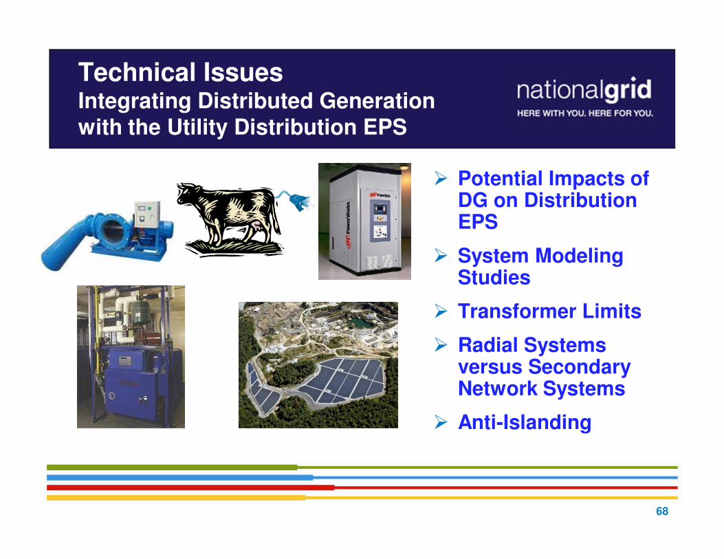
Technical Issues Integrating Distributed Generation with the Utility Distribution EPS
� Potential Impacts of DG on Distribution EPS
� System Modeling Studies
� Transformer Limits
� Radial Systems versus Secondary Network Systems
� Anti-Islanding
68
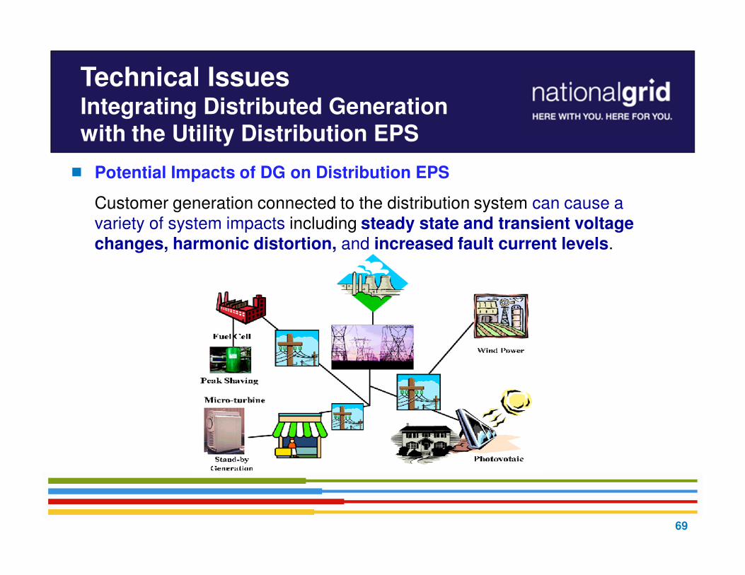
� Potential Impacts of DG on Distribution EPS
Customer generation connected to the distribution system can cause a variety of system impacts including steady state and transient voltage changes, harmonic distortion, and increased fault current levels.
Technical Issues Integrating Distributed Generation with the Utility Distribution EPS
69

� System Modeling Studies
The purpose of impact studies is to identify the severity of system impacts of the Customer’s generators and the upgrades needed to avoid problems on the Company’s distribution electric power system (EPS).
� Careful engineering can effectively eliminate the potentially
adverse impacts that DG or distributed resource (DR)
penetration could impress on the electric delivery system, such
as exposing system and customer equipment to potential
damage, decrease in power quality, decrease in reliability,
extended time to restoration after outage, and potential risks
to public and worker safety.
Technical Issues Integrating Distributed Generation with the Utility Distribution EPS
70

71
� The IEEE supports the following system issuesthat the utility industry faces with DG penetration on the local EPS, but not limited to:
� voltage
� capacitor operations
� flicker and voltage regulator and LTC operations
� protection coordination
� feeding faults after utility protection opens
� interrupting rating of devices
� faults on adjacent feeders
� fault detection
� ground source impacts and ground fault overvoltages
� single phase interruption on three phase line
� recloser coordination
Technical Issues:System Modeling Studies
� thermal overload and conductor burndown
� risk-of-islanding:
� loss of power grid and sensitivity under light load
� vulnerability and overvoltages
� system restoration and network issues
� harmonic distortion contributions
� power system stability and impact to bulk power network
� system reinforcement
� metering
� telemetering

Technical Issues:System Modeling Studies
� Some IEEE standards used in interconnection studies:
� IEEE 519 “Recommended Practices and Requirements for Harmonic Control in Electrical Power Systems”
� IEEE 1453 “Recommended Practice for Measurement and Limits of Voltage Flicker on AC Power Systems”
� IEEE C37.90.1 “Standard Surge Withstand Capability (SWC) Tests for Relays and Relay Systems Associated with Electric Power Apparatus”
� IEEE C37.90.2 “Standard Withstand Capability of Relay Systems to Radiated Electromagnetic Interference from Transceivers”
� IEEE C37.90.3 “Standard Electrostatic Discharge Tests for Protective Relays”
72

� Transformer Limits- DG Installations less than 600V
�The utility distribution transformers continuous duty nameplate rating is applied to sizing for DG Customer installations to ensure reliability of the supply.
�Exceeding transformer nameplate rating from DG sourcesaffects the transformer normal loading capability and transformer life cycle becomes shortened.
�Replacement later due to overload by DG causes burden on other ratepayers!
Technical Issues Integrating Distributed Generation with the Utility Distribution EPS
73

74
� Radial Systems versus Secondary Network Systems
Technical Issues Integrating Distributed Generation with the Utility Distribution EPS
Area Networks consist of one or more primary circuits from one or more substations or transmission supply points arranged such that they collectively feed secondary circuits serving one (a spot network) or more (an area network) Interconnecting Customers.
Technical Issues: Limits on Distribution EPS - Radial
� DG saturation refers to the point at which large amounts of parallel generation are installed, whether by a single large facility or multiple facilities in aggregate, such that it becomes technically infeasible to operate on a single distribution feeder.
� A resulting example is excessive voltage regulation issues associated with intermittent resources like solar and wind. IEEE 1547 is recognized by the applicable Company tariff, P.S.C. 220 Rule 53 providing technical guidance whereby voltage regulation impacted by DG is a limiting factor.
� It is expected due to the DG market that distribution feeders in many areas will reach the saturation point based on the application growth rate in those areas.
� Stability issues due to generation exceeding the feeder load causing back feed to the transmission system will need to be addressed where DG saturation occurs.
75

� DG reduces load on the system
� Multiple systems on a line can pose unique challenges
Technical Issues: Limits on Distribution EPS - Radial
76

Technical Issues:Limits on Distribution EPS - Radial
�First check – “How is EPS affected and how much is acceptable on it (other customers on the feeder)?”
Example: Intermittent Resources - Large PV Inverter-based DG:
� Ramp rates of large PV inverter-based generators can affect EPS operations and power quality.
� Geographic diversity effects not yet fully understood.
77

� Interconnection Applications on non-dedicated circuits:
� Largest wind application is 4.5 MVA on 13 kV class circuits
� Largest Solar application is 6 MVA on 23 kV class circuits
� Interconnection Applications on dedicated circuits:
� Largest wind application is 30 MVA on 34.5 kV class circuits
� Largest Solar application is 9 MVA on 13 kV class circuits
Technical Issues:Limits on Distribution EPS - Radial
78

� Anti-Islanding
� IEEE 1547 requires any Distributed Generator (DG) on a distribution feeder to be detected and be tripped offline within 2 seconds upon formation of an island* from the Area Electric Power System (EPS).
An island is a condition in which a portion of an Area EPS is energized solely by one or more Local DGs while it is electrically separated from the rest of the Area EPS.
� The utility industry recognizes Direct Transfer Trip (DTT) as good utility practice that provides a definitive islanding detection means to disconnect the DG and protect the EPS and the customers it serves.
DTT has inherent high costs and physical limitations of installing leased telecommunication line on the EPS and at the generator(s).
* The DG’s internal protection system is designed with protective functions according to IEEE 1547
to ensure that there is proper voltage, frequency, and phase angle conditions between the Company’s
EPS and the DG system, before the generator is permitted to parallel (5 minutes after the Company
circuit is energized).
Technical Issues Integrating Distributed Generation with the Utility Distribution EPS
79

National Grid uses three main “tests”; any determine if anti-islanding protection is required for exceeding minimum load issue or a protection issue or operating concern:
1. “Feeder Light Load versus Generation Test” – is the aggregate generation* greater than the feeder’s light load?
* Percentage permissible is based on types of DG, i.e. rotating machine, inverter-based, mix of each and system reactive power and impedance characteristics as studied on a case basis.
2. “Fault Sensitivity and Temporary Overvoltage Test” – can the DG facility detect pertinent faults that would occur on the feeder, or line section of the feeder? – can run on times over 2 seconds cause temporary overvoltages to exceed equipment ratings and affect other customer equipment?
3. “Feeder Selectivity Test” – can the DG facility be connected to another circuit that has an automatic transfer scheme enabled?
Note:
� DG Customer’s protective device coordination study demonstrates generation voltage and/or frequency protection will trip within 2.00 seconds for the loss of the utility source (e.g. feeder breaker trip). This will require subsequent compliance verification of the relays and their trip functional tests.
Technical Issues Integrating Distributed Generation with the Utility Distribution EPS
80
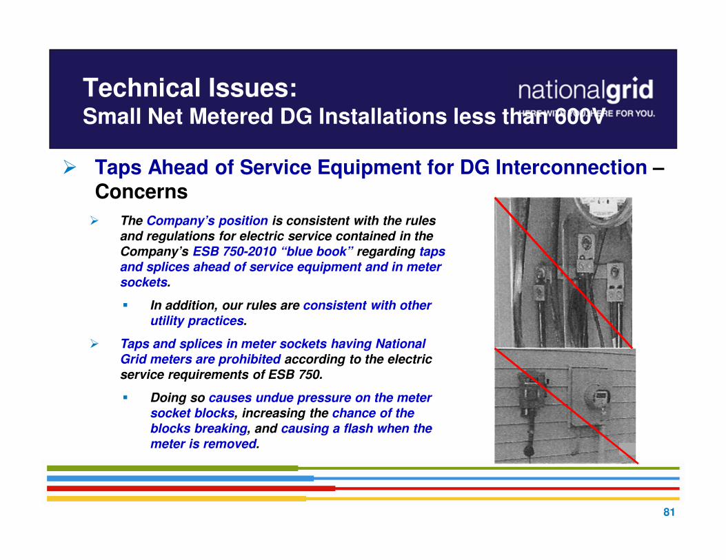
� Taps Ahead of Service Equipment for DG Interconnection –Concerns
Technical Issues:Small Net Metered DG Installations less than 600V
� The Company’s position is consistent with the rules
and regulations for electric service contained in the
Company’s ESB 750-2010 “blue book” regarding taps
and splices ahead of service equipment and in meter
sockets.
� In addition, our rules are consistent with other
utility practices.
� Taps and splices in meter sockets having National
Grid meters are prohibited according to the electric
service requirements of ESB 750.
� Doing so causes undue pressure on the meter
socket blocks, increasing the chance of the
blocks breaking, and causing a flash when the
meter is removed.
81

� Taps Ahead of Service Equipment for DG Interconnection –Concerns
Technical Issues: (cont’d) Small Net
Metered DG Installations less than 600V
OK
82

� Where taps and splices are to be considered ahead of service equipment and on the load side of the Company’s revenue meter, please refer to the following guidance according to ESB 750 and the NEC.
1. The proposed tap or splice shall be made in an approved enclosure external from the revenue meter enclosure.
2. The junction (line tap) box and conduit for service conductors shall meet NEC requirements for the specific installation and its location.
3. Rigid galvanized steel conduit should be used between the revenue meter socket enclosure, junction (line tap) box, existing main service equipment, and distributed generator service equipment.
4. Wire bending radius shall meet NEC requirements and not cause undue pressure on terminations to devices.
5. Service conductor splice shall be in accordance with the NEC and listed materials.
6. The distributed generator system’s disconnect shall be listed and labeled service equipment and installed immediately adjacent to the existing service equipment. (See definition of “service equipment” in Section 2.0 of ESB 750.)
7. Each service equipment shall be labeled according to the NEC (see Article 230).
8. Service grounding system shall be installed in accordance with the NEC for the two adjacent service equipment means (see Article 250).
9. The distributed generator system connection shall comply with the applicable Company tariff, ESB 756 Appendix B, or C, or D as applicable, and the NEC.
10. Where modifications to existing service equipment are proposed, the installer shall obtain the manufacturer requirements in writing (see 110.3(B) in the NEC). (This will be required for the local AHJ Code Enforcement requirements to be met.)
11. An approved electrical inspection certificate of the premises wiring changes is required according to Section 1.9 in ESB 750.
Technical Issues: (cont’d) Small Net
Metered DG Installations less than 600V
83

Technical Issues: Upgrades and System Modifications
84

85
� For example in Upstate NY, or MA, or RI, see ESB 756 Appendix B, or C, or D
� See Section 3.0 for Customer Interface Procedures
� See Exhibit 2 for Company milestone requirements for projects not
covered by the simplified process (i.e. complex)
� Ensure all technical information required in the DG application under the applicable National Grid tariff is complete and legible. Additional
manufacturer technical data may be submitted for understanding the
specified electric source’s characteristics to perform the studies.
Technical Issues:Technical Process End-to-End
Refer to the appropriate Appendix of ESB 756 for the state jurisdiction where DG application is made.

86
Technical Issues:Technical Submittals for Utility Review
Recommended Guidelines for Residential and Commercial Single-line Diagram Submittals (see Exhibit 5
& Figures 1 & 2 in ESB 756
Appendix B, or C, or D)

Post ISA Coordination
Engineering, Procurement & Construction Process (Overview)
ISA Execution
• Payment Plan• Kick-off Meeting• Preliminary
Engineering• Milestone Plan
Design
• Field Investigation• Detailed Design
Sketches and Specifications
• Construction grade estimates
Procurement/ Permits
• Procuring Long Lead items
• Securing Easements, Right of Way access and/or Environmental permits/ licenses
Engineering
• Recloser and Primary Meter
• Company System Updates
• Compliance Verification
Construction
• Advanced notice for scheduling
• Field Check• Outage coordination• Construction
Energization, Testing & Commissioning
• Field Commissioning and Energization
• Relay Test• RTU Test• Customer
Commissioning
Customer Interface: TSES, Customer Service and Customer Solutions
Po
st
ISA
Co
ord
ina
tio
n -
En
gin
ee
rin
g,
Pro
cu
rem
en
t &
Co
ns
tru
cti
on
P
roc
es
s O
ve
rvie
w
87

Post ISA Coordination
Key Items
• Developing Project Schedule including Interconnection Tasks
• Procuring communication lines for Interconnection – MPLS circuit and Telephone line
• Verizon High Voltage Protection Requirements
• Other Utility Costs
• Design/ Equipment Changes
• Municipal Inspection
• Verizon Pole Installation and Payment
• Testing and Commissioning Plan
• Test Procedure
• Energization Plan
• Long term O&M Arrangement
Note: Please plan ahead for all close-out activities, like witness testing, as they can be time
consuming to coordinate and complete. Please keep all critical milestone date or deadline of commercial operation of the system while planning for witness test.
88
Plan Ahead!
Post ISA Coordination (cont’d)
Witness Testing
89
• The Company in general witness below tests as defined in IEEE 1547-2003 for an interconnection:
• Relay Test
• Functional Trip Test
• In-Service Checks
• Generator/ Inverter Test
• Pre-requisite to schedule a witness test
• Certificate of Completion and/or Municipal Inspection
• Compliance Documentation
• Witness test procedure & Energization plan, if applicable
• Customer pre-testing results
• Witness test procedure
• Contact information for the day of the witness test and brief project description
• Visual inspection and equipment test results
• Relay test, Functional trip test, In service checks, and Generator/inverter test
• Oneline and/or three line diagram, if applicable control logic diagram

Post ISA Coordination (cont’d)
Witness Testing Process Overview
90
Witness Test Documents
• IC submits WT Documents
•Company reviews & approves WT documents
• IC Submits Pre-testing results
•Call to discuss test results and sequence of events
Scheduling Witness Test
• IC requests WT date
•Company confirms WT date & sequence of events
•Company coordinates WT with internal groups
Day of Witness Test
•Relay test
•Functional Trip test
• In-service checks
•Generator/Inverter relay test
Authority To Interconnect
•Company reviews & approves test results
•Company confirms receipts of all compliance documentation
•Company to issue AI letter
• In case of IPP, the site will ONLY be energized first time on the day of the witness test after successful completion of relay test and functional trip test.
• Customer shall perform pre-testing using their own generator source.
• The company needs at least 10 day advance notice to schedule a witness test.
• It is recommended to submit witness test documents at least 30 days prior to the witness test.

91
Future 2014 DG Seminars – MA/RI
Date Utility
May 14 WMECo [UN] (Hadley, MA)
June 11 NSTAR[NU] (Westwood, MA)
July 24 National Grid (Waltham, MA)
September (TBD) National Grid (Providence, RI)
September 10 NSTAR[NU] (Westwood, MA)
October 16 National Grid (North Andover, MA)
November (TBD)
December 10 NSTAR[NU] (Westwood, MA)

� National Grid’s jurisdictional interconnection standards
� technical issues integrating DG into distribution electric power systems
� installations of DG facilitiesNMPC
Customer
PRIMEMOVER
SERVICE POINT/RETAIL DELIVERY
POINT
Gen. Control
PREMISELOADS
MAINSERVICE
EQUIPMENT
PARALLELGENERATOR
NMPC ELECTRICDISTRIBUTION
SYSTEM
UTILITYMETER
PARALLEL GENERATION EXAMPLE
RETAILDELIVERYMETERING
POINT
GENERATORINTERFACE
POINT
92
What we covered

Questions?
Some Questions and Answers
� Why do we need an AC Disconnect?
�See Section 7.0 of MA Interconnection Tariff.
� What could be done to move my project along faster?
�Hire an expert to provide us the complete information.
� Is there feeder capacity information?
�Utility is able to provide pre-application report information. Beyond that an impact study is required.
93