Development of systems and techniques for landing … · Development of Systems and Techniques for...
25
NASA TP c.1 1171 NASA Technical Paper 1171 Development of Systems and Techniques for Landing an Aircraft Using Onboard Television \ Shu W . Gee, Peter C. Carr, William R. Winter, and John A. Manke \ FEBRUARY 1978 \ NASA https://ntrs.nasa.gov/search.jsp?R=19780012171 2018-08-30T00:21:40+00:00Z
Transcript of Development of systems and techniques for landing … · Development of Systems and Techniques for...

NASA TP
c.1 1171
NASA Technical Paper 1171
Development of Systems and Techniques for Landing an Aircraft Using Onboard Television
\
Shu W . Gee, Peter C. Carr, William R. Winter, and John A. Manke
\
FEBRUARY 1978
\
NASA
https://ntrs.nasa.gov/search.jsp?R=19780012171 2018-08-30T00:21:40+00:00Z

TECH LIBRARY KAFB, NM
I llllll 11111 lllll 8 lllll lllll Ill11 Ill1 Ill NASA Technical Paper 1171
Development of Systems and Techniques for Landing an Aircraft Using Onboard Television
Shu W . Gee, Peter C. Carr, William R. Winter, and John A. Manke Dryden Flight Research Center Edwards, Cu Ziforizia
National Aeronautics and Space Administration
Scientific and Technical Information Office
1978
I

DEVELOPMENTOFSYSTEMSANDTECHNIQUESFOR
LANDING AN AIRCRAFT USING ONBOARD TELEVISION
Shu W . Gee, Peter C . Carr, William R . Winter, and John A . Manke
Dryden Flight Research Center
INTRODUCTION
Some recent flight test programs at the NASA Dryden Flight Research Center have been conducted by using remotely piloted scale models of research vehicles to obtain free-flight aerodynamic data (refs. 1 and 2 ) . The skill of a pilot is nec- essary for maneuvering these remotely piloted research vehicles (RPRV's) in and at the boundaries of the flight envelope, as well as for the safe recovery of the vehicles.
A program was initiated to develop systems and techniques for performing horizontal landings with powered RPRV's, such as the Firebee and highly maneu- verable aircraft technology (HIMAT) vehicles. However, during the course of a stall/spin program using an unpowered model of the F-15 airplane (ref. 3 ) , the failure of the primary recovery system necessitated a manual horizontal landing that caused extensive damage to the vehicle. The 3/8-scale F-15 RPRV was designed for recovery by using a midair parachute recovery system (MARS). This landing reoriented the subject program to investigate unpowered steep approach problems and created a sense of urgency that precluded complete data gathering.
The objective of the overall program was to develop a landing technique with which a pilot could consistently and safely land an RPRV using television. Specifi- cally, it was desired to determine (1) which television parameters were directly related to pilot performance and (2) what type and amount of training were required to enable a pilot to perform powered and unpowered landings competently using airborne television from both on board and by using remote control.
To attain these objectives, a closed-circuit television system was installed in a twin-engine general aviation airplane. The pilots made landings with no outside visual reference other than through television. The aircraft was subsequently flown as an RPRV from a ground cockpit with a television monitor of the view from the airborne camera, but still with a safety pilot on board the aircraft. Finally,

the unpowered unmanned 3/8-scale model of the F-15 airplane was air launched and successfully flown and landed from the same ground facility.
Previous studies conducted at the Langley Research Center (ref. 4) and the Ames Research Center (refs. 5 and 6) indicated that landings could be made successfully using television. References 7 to 9 are studies of landings using indirect optical viewing systems which have picture resolution superior to tele- vision. Pilots were able to adapt to these viewing systems and with a certain amount of practice they were able to make landings safely. In all of these studies the landings were made in powered aircraft from shallow approach angles. N o documentation could be found of using indirect viewing or television for making power-off landings from steep approaches or for making takeoffs and landings by remote control.
TEST AIRCRAFT AND EQUIPMENT
The test aircraft used for developing the landing technique is shown in figure 1. One television camera is mounted in the nose and another above the cockpit. The image from either camera can be selected for display in the cockpit instrument panel (fig. 2 ) . The camera mounts permit the camera to be adjusted in pitch and roll, and a 10: 1 zoom lens permits the adjustment of the camera's field of view. Space restrictions limit the size of the test aircraft's television screen to a diagonal dimension of 23 centimeters (9 inches), The screen is 6 1 centimeters (24 inches) from the pilot's eyes which fixes his view angles at 16.5O horizontally and 13O vertically. A curtain attached by self-fastening tape and rails surrounds the left cockpit seat and blocks outside vision. The test airplane has several
IC
., .9
L
E-28786 Figure 1. Test aircraft for landings with television.
2

E-28813 Figure 2. Instrument panel i n test aircraft.
subsystems-a pulse code modulation (PCM) instrumentation telemetry system , an electronic flight control system with hydraulic power actuation , an uplink system , and a television downlink system that interfaces with a ground facility. The ground facility processes the airborne and the ground-cockpit-derived signals and trans- mits control commands to the airplane, enabling the airplane to be flown by remote control. The ground-based cockpit is shown in figure 3 .
E - 2932 0 Figure 3. Ground-based cockpit.
3
I-

RESULTS AND DISCUSSIONS
Test Aircraft Characteristics
The test aircraft has unique landing characteristics because of an unusual combination of aerodynamics and landing gear geometry. The aircraft's attitude on the ground is 5 O nose up. The stall speed of the aircraft at maximum gross weight with the power off, gear down, and flaps fully deflected is 60 knots. Touchdown speeds above 70 knots result in an undesirable nose wheel strike on landing, and touchdown speeds below 55 knots result in a high rate of sink at touchdown.
Because the test airplane has low aerodynamic Dutch roll and yaw damping, the pilot's workload during approach and landing is increased by the presence of turbulence. However, these characteristics were felt to be desirable for this program because they made it more difficult for the pilot to land the airplane consist- ly and safely. It was felt that if the pilot could control this vehicle adequately under these circumstances, he would be able to handle all difficult circumstances.
Development of Test Aircraft System
The first flights were made to assess the problems associated with television landings. The judgment of the project pilot was relied on to decide the television parameters necessary for making consistently safe landings with television. The project pilot made takeoffs and landings in the test aircraft with outside reference only through television. A safety pilot rode in the right seat. The project pilot evaluated various combinations of field of view, magnification factor, camera location, and camera depression angle. The following paragraphs describe this experience and the rationale for the final video configuration.
Television presentation .- After the first flight, it was evident that the pilots w o u m n - h o w to-extract information from the two-dimensional picture. The problem lay in recognizing one's situation (attitude, heading, and position in space) with respect to the runway when the field of view was limited. In figure 4 , the situation appears to be a left bank and in line with the runway centerline. In figure 5 , the situation appears to be a right bank and to the left of the runway and perhaps headed parallel to the runway. In figure 6 , the situation appears to be a left bank, uncertain with respect to the runway centerline but definitely headed across the runway.
Figure 7 is the view from exactly the same position in space as in figures 4 to 6 but without restrictions on the field of view or differences in vehicle attitude or heading. The position in space is readily recognized in line with the left edge of the runway.
In analyzing figure 7, it might be noted that, because of perspective, the dashed lines, which represent parallel lines, converge at the point on the horizon that represents infinity. In extracting heading information, the camera angular view relates directly to the displacement of this point from the center of the display because the camera is alined with the axis of the aircraft. If the camera's horizontal
4

\ \ /
I \ I \
/ .. . . . .... .. ....
Figure 4 . Restricted view of runway, aircraft banked.
/ / I \ I I / \
Figure 5 . Restricted view of runway, aircraft banked.
5

I I I I I I I 1 I I 1
Figure 6 . Restricted view of runway, aircraft banked.
/
\ I \
I / I \
\ /
/
\ /
/ /
/
\
\ \
\
\
Figure 7 . Unrestricted view of runway.
6
I

field of view is 14O, then figure 6 depicts a heading of approximately 6 . 5 O to the right of the runway heading. Thus, two corollaries may be drawn: (1) The runway heading reference point is the point where an extension of the runway center- line appears to meet the horizon, and (2) the aircraft's position at any time, regard- less of attitude, is on a line that is perpendicular to the horizon at this point of convergence.
Field of view and magnification factor .- Field of view refers to the horizontal and vertical view angles of the part of the real world that is visible through the television camera lens (that i s , camera lens angle) . During the first flights, while the television system was being developed, a 10: 1 zoom lens with a focal length adjustable from 1 2 . 5 millimeters to 125 millimeters was used to adjust the outside field of view.
It was originally thought that looking at the television screen would be like looking at the real world though a hole. The displayed and real images would be expected to appear the same in size and to seem to be in the same positions relative to the pilot. For these reasons, an angular magnification factor of 1 . 0 was thought to be desirable (fig. 8 ) . Since references 5 to 7 were in disagreement on angular magnification and since references 4, 8 , and 9 did not address the problem, the zoom lens was adjusted for a magnifica- tion factor of 1 . 0 for the first flight. It was not practical to vary the size of the television screen in the airplane, so the 61-centimeter (24-inch) distance to the pilot's eye fixed the pilot's eye angle, p (fig. 8 ) . The tested values of p and camera lens angle, a , are shown in figure 9.
\ - Real object
When a magnification factor of 1 . 0 was used, the project pilot felt that the image size appeared to be smaller than actual, although the image sizes on television and through the window were the same when measured. Judgment of height was con- sidered to be unsatisfactory for landing.
When the magnification factor was increased to 1.5, height information was acceptable; however, the narrower field of view failed to provide the pilot with adequate information for roll control and runway lineup. The horizon was no longer in view for roll reference, and the aircraft's motions were exaggerated, creating a feeling of greater sensitivity of aircraft motion to the pilot.
v Figure 8 . Schematic o f angular magnifica- tion. Angular magnification = p / a where a i s horizontal angle subtended b y real object at camera lens and p is horizontal angle subtended b y object image (appear- ing on television screen) at v iewer 's e y e .
7

Eye distance to screen, cm 6 0 -
40
20
Pilot's eye angle to 23-cm (9- in.) diagonal
television screen 1 25
1.2 \
-
-
I I I l l
58
56
54
52
50
48
4612 14 16 18 20 22
\
i 24 23
22 Eye distance to
21
20 i 19
screen, in.
24 ' J18
Focal length mm
Camera lens angle (a)
- Horizontal viewing angle _ _ _ Vertical viewing angle 140 r
7 60
I 70
Figure 9. Angular magnification data.
A magnification factor of 0 . 6 was also tried. Roll control and runway lineup were easy, but image size and height information were inadequate for landing.
A magnification factor of 1 . 2 was found to be an acceptable compromise for landing. The project pilot was able to judge height adequately at the expense of some degradation in roll information. A 50-millimeter lens provided this field of view and was used for the remainder of the program. The resulting 14O horizontal and 1l0 vertical field of view meant that a heading change of more than 7 O moved the runway out of the field of view. When approaches were made with a correction for crosswinds, which was quite common, the runway appeared displaced from the center to near the edge of the television screen, as shown in figure 1 0 .
Figure 10. DispZay presentation during approach with 5 O Zeft crosswind.
8

Camera location .- The camera mounted on top of the fuselage was 1.8 meters (6 feet) above the ground , and the camera mounted in the nose was 1 . 2 meters (4 feet) above the ground. The top camera was used at first because of its prox- imity to the pilotls eyes and because of the possibility that the lower part of the image would blur with the nose camera when the aircraft came close to the ground. The blur did not occur and the project pilot had no difficulty in using either camera, and since the F-15 RPRV's camera was only 0.91 meter (3 feet) above the ground , the nose camera was used for the remainder of the program. A 25-millimeter lens was then installed in the top camera, which was used to help the pilot acquire the runway during the turn to final approach.
Camera depression angle. - The angle of attack of the test airplane at a normal approach speed is 2.5O. A 2.5O camera depression angle was thought to be ideal because the velocity vector would be at the center of the television screen during approaches. However , this depression angle did not permit the pilot to see down close enough in front of the aircraft , making it difficult for him to judge height for landings. When the camera was adjusted to a depression angle of 5O, the horizon was always out of view during approach, but the project pilot was able to make good landings consistently. This depression angle was used for the remainder of the program. With this depression angle, the flightpath velocity vector for no-wind approaches was one-fourth of the way down from the top center of the television screen.
The physical characteristics of the final video configuration were as follows:
Television screen size , diagonal , cm (in .) . . 23 (9)
Camera lens angle, a , deg . . 1 4 . o x 11 Angular magnification factor . 1 . 2
Camera depression angle, deg down . 5
Pilot's eye angle, p , deg . . 16 .5 X 13
Camera lens focal length, mm . 50
It was concluded from the testing during system development that certain concepts had to be understood before precise information could be extracted from the television presentation. These concepts included point of convergence (for heading information) and the perpendicular to horizon (for position information) .
Test Aircraft Shallow Approaches-Pilot on Board
Two pilots who had not yet participated in the program flew approaches to determine the amount of pilot training that was necessary with the test aircraft system. The flight tests were conducted on a 2000- by 50-meter (6000- by 150-foot) concrete runway that has basic Federal Aviation Administration runway markings at the South Base of Edwards A i r Force Base, Calif. The project pilot was the safety pilot for all flights and rated the evaluation pilot's landing performance. A rating scale of from 1 to 4 was used , 1 being "as good a s VFR" , and 4 being "unable to land safely". The two evaluation pilots (pilots A and B) were briefed
9
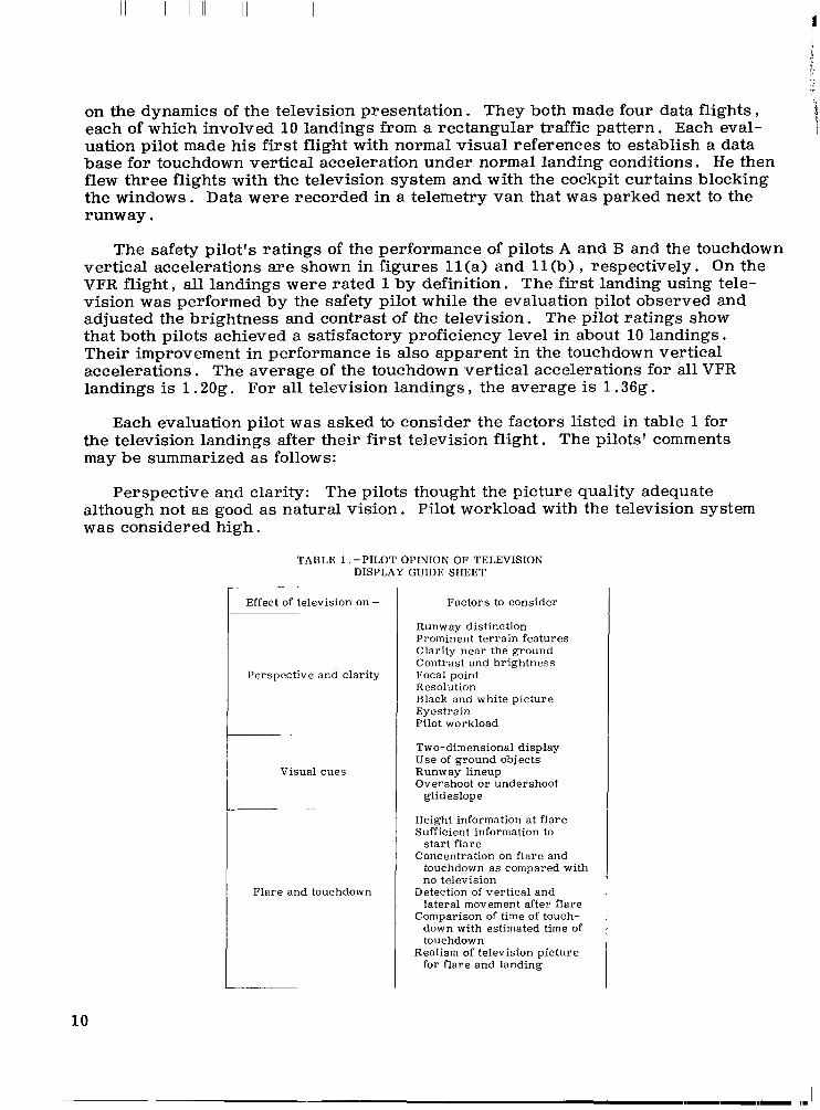
on the dynamics of the television presentation. They both made four data flights each of which involved 1 0 landings from a rectangular traffic pattern. Each eval- uation pilot made his first flight with normal visual references to establish a data base for touchdown vertical acceleration under normal landing conditions. He then flew three flights with the television system and with the cockpit curtains blocking the windows. Data were recorded in a telemetry van that was parked next to the runway.
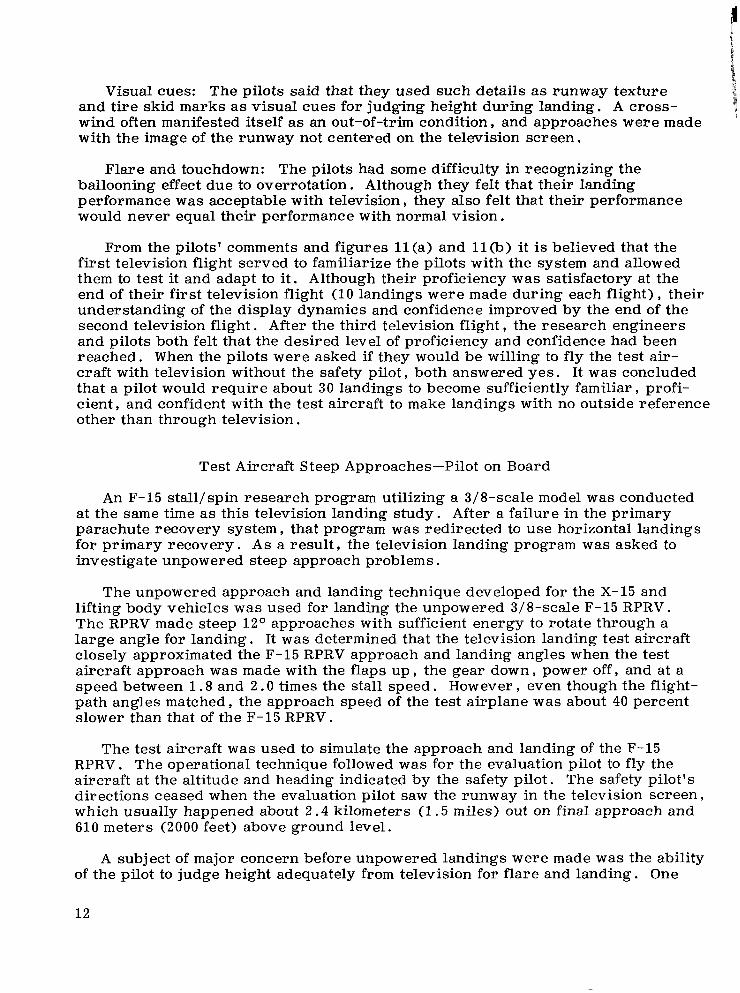
The safety pilot's ratings of the performance of pilots A and B and the touchdown vertical accelerations are shown in figures l l ( a > and ll(b) VFR flighty all landings were rated 1 by definition. The first landing using tele- vision was performed by the safety pilot while the evaluation pilot observed and adjusted the brightness and contrast of the television. The pilot ratings show that both pilots achieved a satisfactory proficiency level in about 10 landings. Their improvement in performance is also apparent in the touchdown vertical accelerations. The average of the touchdown vertical accelerations for all VFR landings is 1.20g. For all television landings the average is 1.36g.
respectively. On the
Each evaluation pilot was asked to consider the factors listed in table 1 for the television landings after their first television flight. The pilots' comments may be summarized as follows:
Perspective and clarity: The pilots thought the picture quality adequate although not as good as natural vision. Pilot workload with the television system was considered high.
TABLE 1 .-PILOT OPINION OF TELEVISION DISPLAY GUIDE SHEET
10
Effect of television on-
Perspective and clari ty
Visual cues
F lare and touchdown
Factors to consider
Runway distinction Prominent te r ra in features Clarity n e a r the ground Contrast and b r igh tness Focal point Resolution Black and white p ic ture Eyestrain Pilot workload
Two-dimensional display Use of ground objects Runway lineup Overshoot or undershoot
glideslope
Height information at f la re Sufficient information to
Concentration on f la re and s t a r t f la re
touchdown a s compared with no television
Detection of ver t ica l and lateral movement after f lare
Comparison of time of touch- down with estimated time of touchdown
for f la re and landing Realism of television p ic ture

VFR f l ight Television f l ight 1 Television f l ight 2 Television f l ight 3 - -,r -- - \ I
0 0 0 0 0 0 0 0 0 0 0 0 0 0 0 i 0 0 .
As good as VFR 1
2 -
3 -
Pilot ra t ing
0 0 0 0 0 0 0 0
0 0
Unable to land 4 I I I I I I I I I I I ~ I I I I I l l l l I l l l l l l l l l l l l l i l l l
2.0 r 0 0 0
0 0 0 0 0 0 0
0 0 0 0 0
0 0 0
I
0 0 0 0 O 0 0 0
0 0 0 0
accelerations.
1.2
3 d 4 Q - I b d !O Landing
( a ) Pilot A .
VFR f l ight Television f l ight 1 Television f l ight 2 Television f l ight 3 7f - -7+ 7 -A ~ \ r - h - -~
0 0 0 0 0 0 0 0 0 0 0 0 i 0 0 0 0
As good as VFR 1
Pi lot 2t 3 t ra t i ng
0 0 0 0 0
0 0 0 0
0 0 0
0
Unable to land 4 l l l l l l l l l l l l l l l l l l l l l l l l l l l l l l l l l l l l l ~ 2.0
0 0
Touchdown vert ical 1.6 0 0 0 0 0 0
0 0 0 0 0
0 1.4
1.2 0 0 0 0 0 0
''O
0 0 0
0 0
1 2 3 4 5 6 7 8 9 1 0 1 2 3 4 5 6 7 8 9 1 0 1 2 3 4 5 6 7 8 9 1 0 1 2 3 4 5 6 7 8 9 1 0 Landing
accelerations, 9
( b ) Pilot B .
Figure 11. Pilot ratings and touchdown vertical accelerations for pilot A and B landings. Tes t aircraft; shallow approaches; pilot on board.
11
Visual cues: The pilots said that they used such details as runway texture and tire skid marks a s visual cues for judging height during landing. A cross- wind often manifested itself as an out-of-trim condition and approaches were made with the image of the runway not centered on the television screen.
Flare and touchdown: The pilots had some difficulty in recognizing the ballooning effect due to overrotation. Although they felt that their landing performance was acceptable with television, they also felt that their performance would never equal their performance with normal vision.
From the pilots' comments and figures l l ( a ) and l l (b) it is believed that the first television flight served to familiarize the pilots with the system and allowed them to test it and adapt to it. Although their proficiency was satisfactory at the end of their first television flight (10 landings were made during each flight) their understanding of the display dynamics and confidence improved by the end of the second television flight. After the third television flighty the research engineers and pilots both felt that the desired level of proficiency and confidence had been reached. When the pilots were asked if they would be willing to fly the test air- craft with television without the safety pilot y both answered yes. It was concluded that a pilot would require about 30 landings to become sufficiently familiar profi- cient and confident with the test aircraft to make landings with no outside reference other than through television.
Test Aircraft Steep Approaches-Pilot on Board
An F-15 stall/spin research program utilizing a 3/8-scale model was conducted at the same time a s this television landing study. After a failure in the primary parachute recovery system that program was redirected to use horizontal landings for primary recovery. A s a result the television landing program was asked to investigate unpowered steep approach problems.
The unpowered approach and landing technique developed for the X-15 and lifting body vehicles was used for landing the unpowered 3/8-scale F-15 RPRV. The RPRV made steep 1 2 O approaches with sufficient energy to rotate through a large angle for landing. It was determined that the television landing test aircraft closely approximated the F-15 RPRV approach and landing angles when the test aircraft approach was made with the flaps up the gear down power off and at a speed between 1.8 and 2 .0 times the stall speed. However path angles matched y the approach speed of the test airplane was about 40 percent slower than that of the F-15 RPRV.
even though the flight-
The test aircraft was used to simulate the approach and landing of the F-15 RPRV. The operational technique followed was for the evaluation pilot to fly the aircraft at the altitude and heading indicated by the safety pilot. The safety pilot's directions ceased when the evaluation pilot saw the runway in the television screen, which usually happened about 2 . 4 kilometers (1.5 miles) out on final approach and 610 meters (2000 feet) above ground level.
A subject of major concern before unpowered landings were made was the ability of the pilot to judge height adequately from television for flare and landing. One
1 2

evaluation pilot, pilot B , and the project pilot, pilot C , made steep unpowered approaches to a runway marked on the dry lakebed. The horizon was not visible during the steep approach, and the sight of two parallel lines against a uniformly textured background made the television landing task difficult; however, both pilots were able to land without the intervention of the safety pilot on their first try. The pilots commented that the workload was very high, but otherwise, there were no serious problems in using television for the RPRV landing. Both pilots made three flights with six landings per flight; touchdown data were not recorded for these flights.
Development of Ground-Based System
The test airplane was then set up to be flown remotely from a ground control facility but with a safety pilot on board. Figure 1 2 is a diagram of the RPRV system. The following paragraphs describe the development of the landing technique used for the test aircraft with television and remote control.
The ground cockpit environment .- The ground cockpit was set up with a television monitor of the same size and located the same distance from the pilot's eyes as in the test airplane. The cockpit and instrument panel were of the general purpose simulator type, and were designed to accommodate instrument and control system changes for engineering evaluations. They were not tailored to resemble
Test vehicle
Up l i n k /
I
I I ' Mode panel I' - Aircraf t response variables
I -
Figure 12. The RPRV system.
13
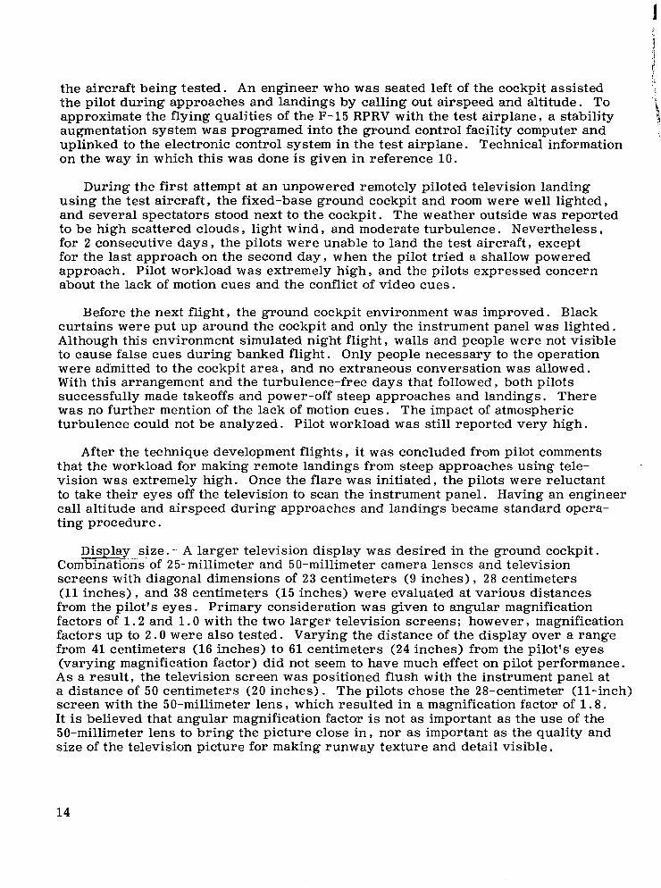
the aircraft being tested. An engineer who was seated left of the cockpit assisted the pilot during approaches and landings by calling out airspeed and altitude. To
augmentation system was programed into the ground control facility computer and uplinked to the electronic control system in the test airplane. Technical information on the way in which this was done is given in reference 10 .
approximate the flying qualities of the F-15 RPRV with the test airplane, a stability i 1
During the first attempt at an unpowered remotely piloted television landing using the test aircraft, the fixed-base ground cockpit and room were well lighted, and several spectators stood next to the cockpit. The weather outside was reported to be high scattered clouds , light wind, and moderate turbulence. Nevertheless , for 2 consecutive days , the pilots were unable to land the test aircraft , except for the last approach on the second day, when the pilot tried a shallow powered approach. Pilot workload was extremely high , and the pilots expressed concern about the lack of motion cues and the conflict of video cues.
Before the next flight, the ground cockpit environment was improved. Black curtains were put up around the cockpit and only the instrument panel was lighted. Although this environment simulated night flight, walls and people were not visible to cause false cues during banked flight. Only people necessary to the operation were admitted to the cockpit area, and no extraneous conversation was allowed. With this arrangement and the turbulence-free days that followed , both pilots successfully made takeoffs and power-off steep approaches and landings. There was no further mention of the lack of motion cues. The impact of atmospheric turbulence could not be analyzed. Pilot workload was still reported very high.
After the technique development flights, it was concluded from pilot comments that the workload for making remote landings from steep approaches using tele- vision was extremely high. Once the flare was initiated, the pilots were reluctant to take their eyes off the television to scan the instrument panel. Having an engineer call altitude and airspeed during approaches and landings became standard opera- ting procedure.
Display sizel- A larger television display was desired in the ground cockpit. Combinations of 25-millimeter and 50-millimeter camera lenses and television screens with diagonal dimensions of 23 centimeters (9 inches) , 28 centimeters (11 inches) , and 38 centimeters (15 inches) were evaluated at various distances from the pilot's eyes. Primary consideration was given to angular magnification factors of 1 . 2 and 1 . 0 with the two larger television screens; however , magnification factors up to 2 . O were also tested. Varying the distance of the display over a range from 41 centimeters (16 inches) to 6 1 centimeters (24 inches) from the pilot's eyes (varying magnification factor) did not seem to have much effect on pilot performance. A s a result , the television screen was positioned flush with the instrument panel at a distance of 50 centimeters (20 inches). The pilots chose the 28-centimeter (ll-inch) screen with the 50-millimeter lens , which resulted in a magnification factor of 1.8. It is believed that angular magnification factor is not as important as the use of the 50-millimeter lens to bring the picture close in , nor as important as the quality and size of the television picture for making runway texture and detail visible.
14

Roll attitude information. - The horizon was not visible in the television screen because of the camera depression angle and the steep approach angle, so attitude information could not be derived. The workload was so high that the pilots had difficulty moving their eyes momentarily from the television picture to check the attitude indicator on the instrument panel. To alleviate this problem, a roll attitude repeater above the television screen was rigged with a piece of wire mounted in front of the picture to provide roll reference. The two pilots bent the wire differ- ently and used it differently, One pilot bent the wire to cross in front of the picture to represent a horizon (fig. 3); he also required the roll repeater to be reversed, creating an "outside looking in'' display. The other pilot bent the wire to encircle the television screen except for a pointer at the center bottom to resemble the roll pointer of an attitude display. The wire configuration for this pilot is shown in figure 13.
E-29319 Figure 13. Ground cockpit. Note wire frame i n front of television monitor.
Effects of sun angle.- It was noticed that sun angle had an effect on the tele- vision picture's contrast. During a 360° turn, the television picture faded when the camera was headed toward the sun and showed the most contrast when it was headed away from the sun. This effect seemed to be a function of camera lens focal length, inasmuch as the wide-angle lens was less affected by sun angle.
the sun. On one occasion, contrast was readjusted during a steep approach when the horizon was out of view. When the landing flare was made, and the horizon and sky came back into view, the entire area of the ground became black and ground objects and markings could not be distinguished. The increase in light intensity caused by sky light entering the camera lens caused the television's automatic gain control in the contrast circuit to saturate. To prevent this from happening again, a ground cockpit crew member controlled the television contrast manually during subsequent approaches and landings.
The picture was normally adjusted for contrast when the camera was away from
15

Touchdown data .- During the technique development flights , touchdown accelerations were recorded along with pilot comments (table 2 ) . In some cases not identified in the comments, landing assistance was provided by the safety pilot, who could not always prevent a landing that was firmer than desired. The average touchdown vertical acceleration was 1.51g.
I Flight I Approach
TABLE 2 .-TOUCHDOWN DATA DURING GROUND-BASED COCKPIT TECHNlQUE DEVELOPMENT FLIGHT
[Average vertical acceleration: 1 . 5 1 g l
Lens focal length, m m
50
1 50
1 50
1
1
5r 1
50
25 1 50
i 25
50 +
Screen, diagonal, cm (in.)
23 (9)
23 (9)
23 ( 9 )
23 (9) 28 (11) 38 (15) 28 (11)
1 23 (9) 28 (11)
Vertical acceleration, g
1 . 3 6 1 . 1 6 1 . 2 6 1 . 9 4 1 . 8 0
1 . 8 0 1 . 2 0 1 . 4 0 1 . 4 8 1 .80 1 . 7 0 1 . 7 4 1 . 3 2
1 . 4 1 . 2 4
1 . 2 8
2 . 0 0 2 . 0 + 1 . 6 0 1 . 1 6
1 . 0 6 1 . 8 0 1 . 5 2 1 . 4 0 2 .oo 1 . 8 2
1 . 6 2 1 . 0 9 1 . 2 4 1 . 6 4 1 . 2 4 1 . 6 2 1 . 2 0
. __
Pilot comments
Too high Increased elevator stick forces to maximum High workload, flared high Reduced aileron and rudder forces Safety pilot takeover
[Airspeed] got slow, difficulty in lineup None None None None Hit nose wheel first Power on Drift to right
[Curtains installed around cockpit and lighting lowered1
None None None None
Grease job None None None None None
None Beautiful None Loss of television at 10 m (30 ft) None Off runway centerline None
-
Test Aircraft Steep Approaches-Remote Pilot
In preparation for landing the F-15 RPRV, the pilots practiced making remotely piloted steep approaches and landings with television using the test airplane as an airborne simulator. The safety pilot on board the test aircraft always made the first takeoff. Once airborne , the ground-based control system was engaged , and in many cases the RPRV pilot flew the remainder of the mission. This included the rest of the takeoffs , flying the traffic patterns , landings , and taxiing back to and parking on the ramp. The safety pilot was required to set the brakes and shut the engines off.
Figure 14 shows the vertical accelerations at touchdown during remotely piloted television practice landings for the two pilots. Each data point represents one landing on the date indicated. In some cases , the number of landings is known , but no data were available. Each pilot practiced making landings in the test aircraft
16

1975 0
0 0
0
0
0
9/18 0
0
0 0 0 I o 0 10114 0 0 l o 0 0 0
0 0
0 0
1975 - 10115 0
7/29 1 oo 10116 10117 7/31 [ 0
0 0 0
0 0 I o 0
0 8112 I 0 10/31
8/15 E - 1 5 RPRV f l ight L
1113
8/29 F-15 RPRV fl ight l o 0
0 I% 11/4
F-15 RPRV fl ight E F-15 RPRV fl ight 11/5 1116 0
t - 0 11/7 F-15 RPRV fl ight t o 0 0 0
lU4 I oo 11/13 I 0 0
0 0
0 0 0
0 0
0 0
I I I I I 1.0 1.2 1.4 1.6 1.8 2.0
Touchdown vert ical accelerations, g
0 0
12/9 I oo 0
12/12 F-15 RPRV fl ight 12/15 F-15 RPRV fl ight
1 I 1.u Touchdown vert ical
accelerations, g
1.0 1.2 1.4 1.6 1.8 2.0 c
( a ) Pilot B . ( b ) Pilot C .
Figure 14. Vertical acceleration at touchdown of test aircraft during remotely piloted television practice landings for two pilots. Steep approaches. F-15 RPRV fl ight denotes p i l o t readiness for or actual F - 1 5 RPRV landing.
17

i
until he felt he was ready to land the F-15 RPRV. flights are indicated denote pilot readiness for an actual F-15 RPRV landing.
The dates where F-15 RPRV i
The I number of television landings each pilot made in the test aircraft in preparation for F-15 RPRV landings decreased after the first F-15 RPRV landing. The average vertical acceleration at touchdown for dl data points is 1.50g. Each pilot stopped flying for about a month (pilot B from November 4 to December 1, and pilot C from September 18 to October 14) and resumed flying without a noticeable change in touchdown acceleration. None of the landings made during these flights required assistance from the safety pilot. Weather conditions varied from calm to crosswinds with light to moderate turbulence.
\
F-15 RPRV Steep Approach Experience
The purpose of the 3/8-scale F-15 RPRV program was to conduct spin research. The RPRV was carried aloft on a B-52 airplane, and on a typical flight it was launched at 15 , 000 meters (45 , 000 feet). The RPRV was spun down to an altitude of approximately 6000 meters (18 , 000 feet) , where recovery was initiated and the approach for landing was started. An entire flight lasted about 4 minutes.
On the day of an F-15 RPRV flight, and prior to the flight, the television test aircraft was flown and landed by the safety pilot with the television picture trans- mitted to the ground cockpit. The picture was viewed by the F-15 RPRV pilot. This flight provided a qualitative check on surface wind and turbulence conditions and the effects of sun angle on the television picture. The test airplane could not be flown remotely at this time because it takes about 8 hours to change the configu- ration of the ground cockpit, and the cockpit was configured for the F-15 RPRV.
In the course of the 3/8-scale F-15 stall/spin program, nine successful horizon- tal landings were made from steep approaches using television. Figure 15 shows the vertical accelerations at touchdown for these landings. The average of the vertical accelerations was 2 . l g . The fact that this average was higher than for the test aircraft was attributed to the differences between the landing gear of the test aircraft and that of the F-15 RPRV. The F-15 RPRV had a tricycle skid arrangement, whereas the test aircraft had a tricycle wheel arrangement.
0 o o Touchdown vert ical 2.0 o o
accelerations, 1.8 0 :::I , , I , I , 9
1.2 1.0 ! I
1 2 3 4 5 6 7 8 9 F-15 RPRV landing
Figure 15. Vertical accelerations at touchdown for nine F - 1 5 RPRV landings.
18

The approach and landing procedures developed with the test aircraft were applied to the F-15 RPRV operations. The pilot workload was considered very high. The pilots called the use of the test aircraft invaluable. At the end of the program the use of the test aircraft as a simulator was considered essential to the success of landing the F-15 RPRV.
Some other things happened during the F-15 RPRV spin program that are worthy of mention. During the approach for the first F-15 RPRV landing, the television picture fogged over at an altitude of about 3000 meters (9000 feet). The fog started to clear on final approach at an altitude of about 1300 meters (4000 feet), and a safe landing was made. On the next flight, the television picture fogged again, but this time it did not clear, so a parachute was deployed for recovery. The changes in temperature and humidity during the 3-minute descent from an altitude of 15,000 meters (45,000 feet) to an altitude of 3000 meters (9000 feet) caused condensation on the television camera housing and lens cover glass. The problem was solved by displacing the air that contained the moisture by bleeding pressurized dry nitrogen into the cockpit canopy. area where the television camera was located and then exhausting the nitrogen into the atmosphere. Two other F-15 RPRV flights were aborted because the television display became blurred before the launch altitude was reached. In one case, vibration caused the television camera lens to unscrew and fall off, and in the other case the television camera's electronics failed. Since the television system, like any other system, is subject to failure, the importance of a backup system should not be overlooked.
The average touchdown vertical accelerations for various flight test phases are presented in table 3. Records of the number of landings or touchdown vertical accelerations were not kept during the development of the test aircraft system, so that flight phase is not shown.
TABLE 3 . -TOUCHDOWN VERTICAL ACCELERATIONS FOR VARIOUS FLIGHT TEST PHASES
Flight phase
Test aircraft , shallow approaches pilot on board , VFR
Test aircraft , shallow approaches pilot on board , television
Test aircraft , steep approaches, pilot on board , television
Development of ground-based system
Test aircraft , steep approaches, remote pilot
F-15 RPRV, steep approaches
Number of fliEhts/landings -
Pilot B
1/10
Pilot C
_ - -
6
8/32
515
3
10162
~
414
Average vertical acceleration
a t touchdown, g
1.20
1.36
No data
1.51
-~
1.50
2.10
19

CONCLUSIONS
A program was conducted to develop the equipment and technique required for landing an RPRV. A number of landings were made in a test aircraft using only television for outside visual reference. Pilots landed this test aircraft from on board the aircraft and from a ground-based cockpit using remote control. The program ended with nine successful horizontal landings made from steep approach with the F-15 RPRV. Certain conclusions were reached from the process of devel- oping the test aircraft and ground-based systems.
1. Certain concepts must be understood before precise situation information can be extracted from the television presentation.
2 . About 30 landings were required for a pilot to become sufficiently familiar, proficient, and confident with a test aircraft to make powered landings with no outside reference other than through television.
3 . The pilot workload for making remote landings from steep approaches using television is extremely high.
4 . The use of the test aircraft as an RPRV simulator was considered essential to the success of landing the F-15 RPRV.
Dryden Flight Research Center National Aeronautics and Space Administration
Edwards, Calif . , June 17, 1977
20

REFERENCES
1. R e e d , R . Dale: RPRVs - The First and Future Flights. A s t r o n a u t . A e r o n . , vol. 1 2 , no. 4 , A p r . 1974, pp. 26-42.
2 . Layton , G a r r i s o n P . : A New E x p e r i m e n t a l Flight R e s e a r c h Technique: The Remotely Piloted A i r p l a n e . F l i g h t / G r o u n d Testing Facilities Cor re l a t ion , AGARD-CP-187 , A p r . 1976, pp. 13-1-13-7.
3. Holleman , Euc l id C . : S u m m a r y of Flight Tests To De te rmine the Spin and Control labi l i ty C h a r a c t e r i s t i c s of a Remotely Piloted , Large-Scale (3/8) Fighter A i r p l a n e Model. NASA TN D-8052 , 1976.
4 . R e e d e r , John P . ; and Kolnick , Joseph J . : A Br ie f Study of Closed-Circui t Television f o r A i r c r a f t L a n d i n g . NASA T N D-2185 , 1964.
5 . Kibort , B e r n a r d R . ; and D r i n k w a t e r , Fred J . 111: A Flight Study of Manual B l ind L a n d i n g P e r f o r m a n c e U s i n g Closed C i r c u i t Television D i s p l a y s . NASA TN D-2252 , 1964.
6 . C h a s e , Wendell D .: Evaluat ion of Several TV Disp lay S y s t e m s f o r V i sua l Simulat ion of the L a n d i n g A p p r o a c h . NASA TN D-6274 , 1971.
7 . Roscoe , Stan ley N . ; H a s l e r , Scott G . ; and D o u g h e r t y , Dora J . : Periscope: Modification , Practice , and V a r i o u s Condit ions of Flight. Human F a c t o r s , vol. 8 , no. 1, Feb. 1966, pp. 13-40.
Flight by Making Takeoffs and Land ings ; The In f luence of Image
8 . Layton , G a r r i s o n P . , Jr . ; and Dana , William H . : Flight Tests of a Wide-Angle , I n d i r e c t Optical V iewing Sys tem in a High-Performance Jet A i r c r a f t . NASA TN D-3690, 1966.
9 . Ga ids i ck , Haro ld G . ; D a n a , William H . ; and McCracken , R o b e r t C . : Evaluat ion of an Ind i r ec t V iewing Sys tem f o r Lift ing-Body Termina l -Area Navigat ion and L a n d i n g Tasks. NASA TN D-5299 , 1969.
10. E d w a r d s , John W . ; and Dee t s , Dwain A . : Development of a Remote Digi ta l Augmentat ion S y s t e m and Applicat ion to a Remotely Piloted R e s e a r c h Veh ic l e . NASA TN D-7941 , 1975.
2 1

1. Report No. I 2. Government Accession No.
19. Security Classif. (of this report)
Unclassified
NASA TP-1171 . . I 4. Title and Subtitle
DEVELOPMENTOFSYSTEMSANDTECHNIQUESFOR LANDING AN AIRCARFT USING ONBOARD TELEVISION
20. Securiry Classif. (of this page) J 21. N;;; Pages
Unclassified $3.25 I,
7. Authorb)
Shu W . Gee, Peter C . Carr , William R . Winter, and John A . Manke
- - .
9. Performing Organization Name and Address
Dryden Flight Research Center P . 0. Box 273 Edwards, California 93523
12. Sponsoring Agency Name and Address
National Aeronautics and Space Administration Washington, D .C . 20546
__ _ _ 15. Supplementary Notes
. ._ __ - . .-
16. Abstract
3. Recipient's Catalog No.
5. Report Date I
8. Performing Organization Report No.
I 199-53-04
. 13. Type of Report and Period Covered
14. Sponsoring Agency Code
.. . .-
A flight program was conducted to develop a landing technique with which a pilot could consistently and safely land a remotely piloted research vehicle (RPRV) without outside visual reference except through television. Otherwise, instrumentation was standard. The report considers such factors as the selection of video parameters, the pilot's understanding of the television presentation, the pilot's ground cockpit environment, and the operational procedures for landing. About 30 landings were necessary for a pilot to become sufficiently familiar and competent with the test aircraft to make powered approaches and landings with outside visual references only through television. When steep approaches and landings were made by remote control, the pilot's workload was extremely high. The test aircraft was used as a simulator for the F-15 RPRV, and as such was considered to be essential to the success of landing the F-15 RPRV.
17. Key Words (Suggested Author(sJ I
Landing performance Television landings Remotely piloted research vehicles
_.
18. Distribution Statement
Unclassified - Unlimited
STAR Category: 05
NASA-Langley, 1978

,
S P E C I A L FOURTH CLASS M A I L National Aeronautics and Space Administration . BOOK
Washington, D.C. 20546
Postage and Fees Paid National Aeronautics and Space Administration N A S A 4 5 1 ,
Official Business
Penalty for Private Use, $300
2 1 lU,A, 021778 S00903DS DEPT O F THE A I 3 FORCE AF WEAPONS L R R O R &TO RY ATTN: TECRNICAZ L I B I i A B P {SUL) HIBTZAND AFB IUM 87117
POSTMASTER :
, I
- .
I I