Design of a Bearingless Outer Rotor Induction Motor
15
energies Article Design of a Bearingless Outer Rotor Induction Motor Yuxin Sun, Jingwei Tang * and Kai Shi School of Electrical and Information Engineering, Jiangsu University, Zhenjiang 212013, China; [email protected] (Y.S.); [email protected] (K.S.) * Correspondence: [email protected]; Tel.: +86-157-0610-7126 Academic Editor: Frede Blaabjerg Received: 16 December 2016; Accepted: 11 May 2017; Published: 17 May 2017 Abstract: A bearingless induction (BI) motor with an outer rotor for flywheel energy storage systems is proposed due to the perceived advantages of simple rotor structure, non-contact support and high speed operation. Firstly, the configuration and operation principle of the proposed motor are described. Then several leading dimensional parameters are optimally calculated for achieving the maximum average values and the minimum ripples of torque output and suspension force. Finally, by using the finite element method, the characteristics and performance of the proposed machine are analyzed and verified. Keywords: bearingless motor; finite element analysis; induction motor; motor optimization design; outer rotor 1. Introduction Due to their merit of high power density, high and super-high speed motors have attracted more and more attention for a lot of industry applications [1]. However, the conventional high speed motor usually suffers from some inevitable disadvantages which limit its development and application, such as friction, acoustic noise and the need for regular lubrication because of the adoption of mechanical bearings. Fortunately, magnetic bearings have been proposed in recent years, so that motors with non-contact support, namely magnetic bearing motors, can be produced to avoid the problems caused by mechanical bearings. However, conventional magnetic bearing motors are usually bulky, and require a number of wiring connections as well as many single phase inverters [2]. Based on the similarities between the configurations of magnetic bearing and conventional electric machines, a variety of bearingless machines have been presented and widely investigated, such as bearingless induction (BI) motors [3], bearingless permanent magnet motors [4], superconducting bearingless machines [5] and bearingless switched reluctance generators [6], in which a set of suspension winding (SW) is embedded in the stator slots along with the conventional armature winding. Bearingless motors therefore possess a series of advantages compared to magnetic bearing motors, such as shorter shafts, higher critical speed, and more applicability for demanding super-high speed operation. Compared to the other types of bearingless motors, BI motors have the merits of simpler rotor structures, lower cost and higher reliability. In [7], the axial oscillation production mechanism of a BI motor with a skewed internal rotor was analyzed, based on which an improved configuration with two tandem rotors skewed in opposing directions was presented to cancel the axial forces. In [8], a three-phase BI motor with divided windings was proposed and an independent control method for each phase was employed to enhance its fault tolerance capability. In this paper, a BI motor with an outer rotor for flywheel energy storage systems is proposed. The motor configuration is shown and its operation principle explained in Section 2. In Section 3, the optimization design of the proposed machine is discussed and its characteristics are analyzed by using the finite element analysis (FEA) method. Then the key dimensional parameters and Energies 2017, 10, 705; doi:10.3390/en10050705 www.mdpi.com/journal/energies
Transcript of Design of a Bearingless Outer Rotor Induction Motor

energies
Article
Design of a Bearingless Outer Rotor Induction Motor
Yuxin Sun, Jingwei Tang * and Kai Shi
School of Electrical and Information Engineering, Jiangsu University, Zhenjiang 212013, China;[email protected] (Y.S.); [email protected] (K.S.)* Correspondence: [email protected]; Tel.: +86-157-0610-7126
Academic Editor: Frede BlaabjergReceived: 16 December 2016; Accepted: 11 May 2017; Published: 17 May 2017
Abstract: A bearingless induction (BI) motor with an outer rotor for flywheel energy storage systemsis proposed due to the perceived advantages of simple rotor structure, non-contact support andhigh speed operation. Firstly, the configuration and operation principle of the proposed motor aredescribed. Then several leading dimensional parameters are optimally calculated for achieving themaximum average values and the minimum ripples of torque output and suspension force. Finally,by using the finite element method, the characteristics and performance of the proposed machine areanalyzed and verified.
Keywords: bearingless motor; finite element analysis; induction motor; motor optimization design;outer rotor
1. Introduction
Due to their merit of high power density, high and super-high speed motors have attracted moreand more attention for a lot of industry applications [1]. However, the conventional high speed motorusually suffers from some inevitable disadvantages which limit its development and application,such as friction, acoustic noise and the need for regular lubrication because of the adoption ofmechanical bearings. Fortunately, magnetic bearings have been proposed in recent years, so thatmotors with non-contact support, namely magnetic bearing motors, can be produced to avoid theproblems caused by mechanical bearings. However, conventional magnetic bearing motors are usuallybulky, and require a number of wiring connections as well as many single phase inverters [2].
Based on the similarities between the configurations of magnetic bearing and conventional electricmachines, a variety of bearingless machines have been presented and widely investigated, such asbearingless induction (BI) motors [3], bearingless permanent magnet motors [4], superconductingbearingless machines [5] and bearingless switched reluctance generators [6], in which a set of suspensionwinding (SW) is embedded in the stator slots along with the conventional armature winding. Bearinglessmotors therefore possess a series of advantages compared to magnetic bearing motors, such as shortershafts, higher critical speed, and more applicability for demanding super-high speed operation.Compared to the other types of bearingless motors, BI motors have the merits of simpler rotorstructures, lower cost and higher reliability. In [7], the axial oscillation production mechanism of a BImotor with a skewed internal rotor was analyzed, based on which an improved configuration withtwo tandem rotors skewed in opposing directions was presented to cancel the axial forces. In [8],a three-phase BI motor with divided windings was proposed and an independent control method foreach phase was employed to enhance its fault tolerance capability.
In this paper, a BI motor with an outer rotor for flywheel energy storage systems is proposed.The motor configuration is shown and its operation principle explained in Section 2. In Section 3,the optimization design of the proposed machine is discussed and its characteristics are analyzedby using the finite element analysis (FEA) method. Then the key dimensional parameters and
Energies 2017, 10, 705; doi:10.3390/en10050705 www.mdpi.com/journal/energies

Energies 2017, 10, 705 2 of 15
electromagnetic performance features are presented in Section 4. Finally, some conclusions are drawnin Section 5.
2. Motor Configuration and Operation Principle
Figure 1 shows the proposed BI motor with outer rotor, in which a squirrel-cage rotor is adopted.It can be seen that the configuration is very similar to that of a conventional outer rotor induction motor.The key difference is that there are two sets of 3-phase windings, namely the SW and the traditionalarmature winding, named torque winding (TW) in this paper, placed in the stator slots. Furthermore,in order to reduce the iron losses in the rotor core and pulsating losses in the tooth portion, half-closedpear-shaped slots with small slot openings are adopted in the stator.
Energies 2017, 10, 705 2 of 15
using the finite element analysis (FEA) method. Then the key dimensional parameters and electromagnetic performance features are presented in Section 4. Finally, some conclusions are drawn in Section 5.
2. Motor Configuration and Operation Principle
Figure 1 shows the proposed BI motor with outer rotor, in which a squirrel-cage rotor is adopted. It can be seen that the configuration is very similar to that of a conventional outer rotor induction motor. The key difference is that there are two sets of 3-phase windings, namely the SW and the traditional armature winding, named torque winding (TW) in this paper, placed in the stator slots. Furthermore, in order to reduce the iron losses in the rotor core and pulsating losses in the tooth portion, half-closed pear-shaped slots with small slot openings are adopted in the stator.
Figure 1. Configuration of proposed bearingless outer rotor induction motor.
The rotor suspension of the bearingless motor is achieved based on the Maxwell electromagnetic force due to the resultant field produced by two sets of windings with a different number of poles. To realize stable suspension of the rotating rotor, it is necessary to produce an additional and controllable radial force, so that a unilateral magnetic pull force can be achieved to overcome the external load in the radial direction. By feeding a suitable current into the SW, the balance and symmetry of the rotating magnetic field produced by the TW in the motor airgap can be disturbed. In other words, the magnetic fields in some partial areas of the airgap are enhanced and those in the corresponding symmetrical areas can be weakened due to the contribution of the suspension current. Thus, a radial resultant force, namely a suspension force, is produced in the direction of the enhanced magnetic field. According to the bearingless motor principle, the pole pair numbers of two sets of windings and their electrical frequencies must satisfy Equation (1):
t s s t1, P P ω ω= ± = (1)
where Ps, Pt, ωs and ωt are the pole-pair numbers and electrical frequencies of SW and TW, respectively.
In this paper, Pt = 2 and Ps = 1. When the corresponding currents are fed into the two sets of windings, the theoretical magnetic field distributions of proposed BI outer rotor motor can be depicted as in Figure 2, in which ψt and ψs represent the flux linkage produced by the TW and the SW, respectively.
As shown in Figure 2a, the torque and suspension magnetic fields can be produced by the equivalent torque and suspension currents, respectively, which are drawn using dashed lines and full lines, respectively. It can be seen that the directions of the two magnetic fields in area A are the same, so the resultant magnetic field in area A equals the sum of ψt and ψs. On the other hand, the two magnetic field directions are opposed in area B, thus the total magnetic field in area B is reduced due to ψs. Thus a suspension force in the X-axis positive direction Fx can be obtained. By feeding a reverse current into the SW, the direction of ψs is reversed, so that a suspension force in the opposite direction –Fx can be realized. Similarly, the suspension force Fy and -Fy can be performed by adjusting the current phases of two sets of windings, as shown in Figure 2b. So, it can be concluded that by
Vph-SW
Uph-SW
Wph-SW
Vph-TW
Uph-TW
Wph-TW
Rotor
Stator
Figure 1. Configuration of proposed bearingless outer rotor induction motor.
The rotor suspension of the bearingless motor is achieved based on the Maxwell electromagneticforce due to the resultant field produced by two sets of windings with a different number of poles.To realize stable suspension of the rotating rotor, it is necessary to produce an additional andcontrollable radial force, so that a unilateral magnetic pull force can be achieved to overcome theexternal load in the radial direction. By feeding a suitable current into the SW, the balance andsymmetry of the rotating magnetic field produced by the TW in the motor airgap can be disturbed.In other words, the magnetic fields in some partial areas of the airgap are enhanced and those in thecorresponding symmetrical areas can be weakened due to the contribution of the suspension current.Thus, a radial resultant force, namely a suspension force, is produced in the direction of the enhancedmagnetic field. According to the bearingless motor principle, the pole pair numbers of two sets ofwindings and their electrical frequencies must satisfy Equation (1):
Pt = Ps ± 1, ωs = ωt (1)
where Ps, Pt, ωs and ωt are the pole-pair numbers and electrical frequencies of SW and TW, respectively.In this paper, Pt = 2 and Ps = 1. When the corresponding currents are fed into the two sets
of windings, the theoretical magnetic field distributions of proposed BI outer rotor motor can bedepicted as in Figure 2, in which ψt and ψs represent the flux linkage produced by the TW and theSW, respectively.
As shown in Figure 2a, the torque and suspension magnetic fields can be produced by theequivalent torque and suspension currents, respectively, which are drawn using dashed lines and fulllines, respectively. It can be seen that the directions of the two magnetic fields in area A are the same,so the resultant magnetic field in area A equals the sum of ψt and ψs. On the other hand, the twomagnetic field directions are opposed in area B, thus the total magnetic field in area B is reduceddue to ψs. Thus a suspension force in the X-axis positive direction Fx can be obtained. By feedinga reverse current into the SW, the direction of ψs is reversed, so that a suspension force in the opposite
Energies 2017, 10, 705 3 of 15
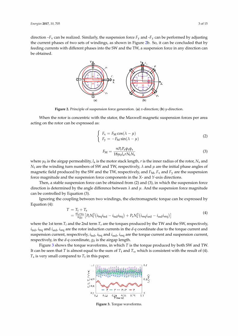
direction –Fx can be realized. Similarly, the suspension force Fy and -Fy can be performed by adjustingthe current phases of two sets of windings, as shown in Figure 2b. So, it can be concluded that byfeeding currents with different phases into the SW and the TW, a suspension force in any direction canbe obtained.
Energies 2017, 10, 705 3 of 15
feeding currents with different phases into the SW and the TW, a suspension force in any direction can be obtained.
(a) (b)
Figure 2. Principle of suspension force generation. (a) x-direction; (b) y-direction.
When the rotor is concentric with the stator, the Maxwell magnetic suspension forces per area acting on the rotor can be expressed as:
( )( )
x M
y M
cos
sin
F = F λ μ
F = F λ μ
-
- -
(2)
t s t sM
0 t s
π=
18 a
P Pψ ψF
μ l rN N (3)
where μ0 is the airgap permeability, la is the motor stack length, r is the inner radius of the rotor, Ns and Nt are the winding turn numbers of SW and TW, respectively, λ and μ are the initial phase angles of magnetic field produced by the SW and the TW, respectively, and FM, Fx and Fy are the suspension force magnitude and the suspension force components in the X- and Y-axis directions.
Then, a stable suspension force can be obtained from (2) and (3), in which the suspension force direction is determined by the angle difference between λ and μ. And the suspension force magnitude can be controlled by Equation (3).
Ignoring the coupling between two windings, the electromagnetic torque can be expressed by Equation (4):
( ) ( )t s
2 2a 0t t tsq trd tsd trq s s ssq srd ssd srq
0
6
π
T T T
l rμPN i i i i P N i i i i
g
= +
= − + − (4)
where the 1st term Tt and the 2nd term Ts are the torques produced by the TW and the SW, respectively, itrd, itrq and isrd, isrq are the rotor induction currents in the d-q coordinate due to the torque current and suspension current, respectively, itsd, itsq and issd, issq are the torque current and suspension current, respectively, in the d-q coordinate, g0 is the airgap length.
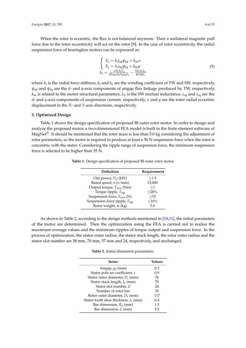
Figure 3 shows the torque waveforms, in which T is the torque produced by both SW and TW. It can be seen that T is almost equal to the sum of Tt and Ts, which is consistent with the result of (4). Ts is very small compared to Tt in this paper.
Figure 2. Principle of suspension force generation. (a) x-direction; (b) y-direction.
When the rotor is concentric with the stator, the Maxwell magnetic suspension forces per areaacting on the rotor can be expressed as:{
Fx = FM cos(λ − µ)
Fy = −FM sin(λ − µ)(2)
FM =πPtPsψtψs
18µ0larNtNs(3)
where µ0 is the airgap permeability, la is the motor stack length, r is the inner radius of the rotor, Ns andNt are the winding turn numbers of SW and TW, respectively, λ and µ are the initial phase angles ofmagnetic field produced by the SW and the TW, respectively, and FM, Fx and Fy are the suspensionforce magnitude and the suspension force components in the X- and Y-axis directions.
Then, a stable suspension force can be obtained from (2) and (3), in which the suspension forcedirection is determined by the angle difference between λ and µ. And the suspension force magnitudecan be controlled by Equation (3).
Ignoring the coupling between two windings, the electromagnetic torque can be expressed byEquation (4):
T = Tt + Ts
= 6larµ0πg0
[PtN2
t(itsqitrd − itsditrq
)+ PsN2
s(issqisrd − issdisrq
)] (4)
where the 1st term Tt and the 2nd term Ts are the torques produced by the TW and the SW, respectively,itrd, itrq and isrd, isrq are the rotor induction currents in the d-q coordinate due to the torque current andsuspension current, respectively, itsd, itsq and issd, issq are the torque current and suspension current,respectively, in the d-q coordinate, g0 is the airgap length.
Figure 3 shows the torque waveforms, in which T is the torque produced by both SW and TW.It can be seen that T is almost equal to the sum of Tt and Ts, which is consistent with the result of (4).Ts is very small compared to Tt in this paper.
Energies 2017, 10, 705 4 of 15
Figure 3. Torque waveforms.
When the rotor is eccentric, the flux is not balanced anymore. Then a unilateral magnetic pull force due to the rotor eccentricity will act on the rotor [9]. In the case of rotor eccentricity, the radial suspension force of bearingless motors can be expressed as:
x i td td m
y i tq tq m
t s 2 t s si
0 t s t s t t
3
8 4
F k i k x
F k i k y
PPL PN kk
lr N N k k rN k
ψψ
μ
= + = +
π= −
(5)
where ki is the radial force stiffness, kt and ks are the winding coefficient of TW and SW, respectively, ψtd and ψtq are the d- and q-axis components of airgap flux linkage produced by TW, respectively, km is related to the motor structural parameters, L2 is the SW mutual inductance, isd and isq are the d- and q-axis components of suspension current, respectively, x and y are the rotor radial eccentric displacement in the X- and Y-axis directions, respectively.
3. Optimized Design
Table 1 shows the design specification of proposed BI outer rotor motor. In order to design and analyze the proposed motor, a two-dimensional FEA model is built in the finite element software of MagNet®. It should be mentioned that the rotor mass is less than 5.0 kg considering the adjustment of rotor parameters, so the motor is required to produce at least a 50 N suspension force when the rotor is concentric with the stator. Considering the ripple range of suspension force, the minimum suspension force is selected to be higher than 55 N.
Table 1. Design specification of proposed BI outer rotor motor.
Definition RequirementOut power, PN (kW) ≥1.5
Rated speed, n (r/min) 15,000 Output torque, Tave (Nm) ≥1
Torque ripple, Trip ≤20% Suspension force, Fave (N) ≥55
Suspension force ripple, Frip ≤10% Rotor weight, m (kg) 5.0
As shown in Table 2, according to the design methods mentioned in [10,11], the initial parameters of the motor are determined. Then the optimization using the FEA is carried out to realize the maximum average values and the minimum ripples of torque output and suspension force. In the process of optimization, the stator outer radius, the stator stack length, the rotor outer radius and the stator slot number are 38 mm, 70 mm, 57 mm and 24, respectively, and unchanged.
Figure 3. Torque waveforms.
Energies 2017, 10, 705 4 of 15
When the rotor is eccentric, the flux is not balanced anymore. Then a unilateral magnetic pullforce due to the rotor eccentricity will act on the rotor [9]. In the case of rotor eccentricity, the radialsuspension force of bearingless motors can be expressed as:{
Fx = kiitdψtd + kmxFy = kiitqψtq + kmy
ki =πPtPsL2
8lrµ0 Nt Nsktks− 3Pt Nsks
4rNtkt
(5)
where ki is the radial force stiffness, kt and ks are the winding coefficient of TW and SW, respectively,ψtd and ψtq are the d- and q-axis components of airgap flux linkage produced by TW, respectively,km is related to the motor structural parameters, L2 is the SW mutual inductance, isd and isq are thed- and q-axis components of suspension current, respectively, x and y are the rotor radial eccentricdisplacement in the X- and Y-axis directions, respectively.
3. Optimized Design
Table 1 shows the design specification of proposed BI outer rotor motor. In order to design andanalyze the proposed motor, a two-dimensional FEA model is built in the finite element software ofMagNet®. It should be mentioned that the rotor mass is less than 5.0 kg considering the adjustment ofrotor parameters, so the motor is required to produce at least a 50 N suspension force when the rotor isconcentric with the stator. Considering the ripple range of suspension force, the minimum suspensionforce is selected to be higher than 55 N.
Table 1. Design specification of proposed BI outer rotor motor.
Definition Requirement
Out power, PN (kW) ≥1.5Rated speed, n (r/min) 15,000
Output torque, Tave (Nm) ≥1Torque ripple, Trip ≤20%
Suspension force, Fave (N) ≥55Suspension force ripple, Frip ≤10%
Rotor weight, m (kg) 5.0
As shown in Table 2, according to the design methods mentioned in [10,11], the initial parametersof the motor are determined. Then the optimization using the FEA is carried out to realize themaximum average values and the minimum ripples of torque output and suspension force. In theprocess of optimization, the stator outer radius, the stator stack length, the rotor outer radius and thestator slot number are 38 mm, 70 mm, 57 mm and 24, respectively, and unchanged.
Table 2. Initial dimension parameters.
Items Values
Airgap, g0 (mm) 0.3Stator pole arc coefficient, c 0.9
Stator outer diameter, Ds (mm) 76Stator stack length, la (mm) 70
Stator slot number, Z 24Number of rotor bar 30
Rotor outer diameter, Dr (mm) 117Stator tooth shoe thickness, ts (mm) 0.4
Bar dimension, Ra (mm) 1.5Bar dimension, L (mm) 5.5
Energies 2017, 10, 705 5 of 15
In order to optimize the structure parameters, which have a great influence on the motor, the singleparameter optimization method [12] is used in this paper. Based on the FEA model, several keydimension parameters are defined, as shown in Figure 4. The design and optimization flow chart isshown in Figure 5. The initial values and optimal ranges, such as stator pole arc coefficient, radius andlength of rotor slot, stator tooth shoe thickness, and so on are shown in Table 3. It should be mentionedthat the suspension force is assumed to be in the X-axis positive direction and the rotor is concentricwith its stator in the optimization design.
Energies 2017, 10, 705 5 of 15
Table 2. Initial dimension parameters.
Items ValuesAirgap, g0 (mm) 0.3
Stator pole arc coefficient, c 0.9 Stator outer diameter, Ds (mm) 76
Stator stack length, la (mm) 70 Stator slot number, Z 24 Number of rotor bar, 30
Rotor outer diameter, Dr (mm) 117 Stator tooth shoe thickness, ts (mm) 0.4
Bar dimension, Ra (mm) 1.5 Bar dimension, L (mm) 5.5
In order to optimize the structure parameters, which have a great influence on the motor, the single parameter optimization method [12] is used in this paper. Based on the FEA model, several key dimension parameters are defined, as shown in Figure 4. The design and optimization flow chart is shown in Figure 5. The initial values and optimal ranges, such as stator pole arc coefficient, radius and length of rotor slot, stator tooth shoe thickness, and so on are shown in Table 3. It should be mentioned that the suspension force is assumed to be in the X-axis positive direction and the rotor is concentric with its stator in the optimization design.
Figure 4. Parameter definition of proposed BI outer rotor motor.
Figure 5. Design and optimization flow chart.
Figure 4. Parameter definition of proposed BI outer rotor motor.
Energies 2017, 10, 705 5 of 15
Table 2. Initial dimension parameters.
Items ValuesAirgap, g0 (mm) 0.3
Stator pole arc coefficient, c 0.9 Stator outer diameter, Ds (mm) 76
Stator stack length, la (mm) 70 Stator slot number, Z 24 Number of rotor bar, 30
Rotor outer diameter, Dr (mm) 117 Stator tooth shoe thickness, ts (mm) 0.4
Bar dimension, Ra (mm) 1.5 Bar dimension, L (mm) 5.5
In order to optimize the structure parameters, which have a great influence on the motor, the single parameter optimization method [12] is used in this paper. Based on the FEA model, several key dimension parameters are defined, as shown in Figure 4. The design and optimization flow chart is shown in Figure 5. The initial values and optimal ranges, such as stator pole arc coefficient, radius and length of rotor slot, stator tooth shoe thickness, and so on are shown in Table 3. It should be mentioned that the suspension force is assumed to be in the X-axis positive direction and the rotor is concentric with its stator in the optimization design.
Figure 4. Parameter definition of proposed BI outer rotor motor.
Figure 5. Design and optimization flow chart.
Figure 5. Design and optimization flow chart.
Table 3. Initial values and optimal range.
Items Initial Values Range
Number of rotor bar 30 28–34Stator pole arc coefficient, c 0.9 0.8–1.0
Stator tooth shoe thickness, ts (mm) 0.4 0.1–0.7Bar dimension, Ra (mm) 1.5 1.3–2Bar dimension, L (mm) 5.5 5–7
Firstly, the average suspension force Fave, is calculated with different airgap lengths and differentsuspension currents. As shown in Figure 6, when the suspension current is less than 3 A, the suspensionforce reduces significantly with the increase of the airgap length. On the other hand, firstly, when the

Energies 2017, 10, 705 6 of 15
current is between 0 A to 3 A, the suspension force increases linearly with the different airgap lengthsand the increase of suspension current. Then, the suspension force decreases due to the saturation ofiron core. When the airgap length is 0.2 mm and the current equals 3 A, the maximum suspensionforce occurs. Taking the manufacture difficulty into account, the airgap length is selected to be 0.3 mmin this paper.
Energies 2017, 10, 705 6 of 15
Table 3. Initial values and optimal range.
Items Initial Values Range Number of rotor bar 30 28–34
Stator pole arc coefficient, c 0.9 0.8–1.0 Stator tooth shoe thickness, ts (mm) 0.4 0.1–0.7
Bar dimension, Ra (mm) 1.5 1.3–2 Bar dimension, L (mm) 5.5 5–7
Firstly, the average suspension force Fave, is calculated with different airgap lengths and different suspension currents. As shown in Figure 6, when the suspension current is less than 3 A, the suspension force reduces significantly with the increase of the airgap length. On the other hand, firstly, when the current is between 0 A to 3 A, the suspension force increases linearly with the different airgap lengths and the increase of suspension current. Then, the suspension force decreases due to the saturation of iron core. When the airgap length is 0.2 mm and the current equals 3 A, the maximum suspension force occurs. Taking the manufacture difficulty into account, the airgap length is selected to be 0.3 mm in this paper.
Figure 6. Fave with different airgap lengths versus suspension current.
Figure 7 depicts the relationship between the suspension force and the rotor bar number, in which the subscripts of ave and rip represent the average and ripple values, respectively. It is shown that Fave and Frip increases and reduces, respectively, with the increase of number of rotor bars. Then the torque output is also analyzed with different rotor bar numbers. As shown in Figure 8, the average torque Tave is almost the same with different bar numbers. It is worth to be mentioned that the torque ripple Trip with 2n bars is obviously higher than that with 2n + 1 bars, where n is a positive integer.
(a) (b)
Figure 7. Fave and Frip versus rotor bar number. (a) Even number of rotor bar; (b) Odd number of rotor number.
(a) (b)
Figure 8. Tave and Trip versus rotor bar number. (a) Even number of rotor bar; (b) Odd number of rotor number.
Fav
e(N
)
00.10.20.30.40.50.6
798081828384858687
28 30 32 34
Fave
Frip
Rotor bar number
Figure 6. Fave with different airgap lengths versus suspension current.
Figure 7 depicts the relationship between the suspension force and the rotor bar number, in whichthe subscripts of ave and rip represent the average and ripple values, respectively. It is shown that Fave
and Frip increases and reduces, respectively, with the increase of number of rotor bars. Then the torqueoutput is also analyzed with different rotor bar numbers. As shown in Figure 8, the average torqueTave is almost the same with different bar numbers. It is worth to be mentioned that the torque rippleTrip with 2n bars is obviously higher than that with 2n + 1 bars, where n is a positive integer.
Energies 2017, 10, 705 6 of 15
Table 3. Initial values and optimal range.
Items Initial Values Range Number of rotor bar 30 28–34
Stator pole arc coefficient, c 0.9 0.8–1.0 Stator tooth shoe thickness, ts (mm) 0.4 0.1–0.7
Bar dimension, Ra (mm) 1.5 1.3–2 Bar dimension, L (mm) 5.5 5–7
Firstly, the average suspension force Fave, is calculated with different airgap lengths and different suspension currents. As shown in Figure 6, when the suspension current is less than 3 A, the suspension force reduces significantly with the increase of the airgap length. On the other hand, firstly, when the current is between 0 A to 3 A, the suspension force increases linearly with the different airgap lengths and the increase of suspension current. Then, the suspension force decreases due to the saturation of iron core. When the airgap length is 0.2 mm and the current equals 3 A, the maximum suspension force occurs. Taking the manufacture difficulty into account, the airgap length is selected to be 0.3 mm in this paper.
Figure 6. Fave with different airgap lengths versus suspension current.
Figure 7 depicts the relationship between the suspension force and the rotor bar number, in which the subscripts of ave and rip represent the average and ripple values, respectively. It is shown that Fave and Frip increases and reduces, respectively, with the increase of number of rotor bars. Then the torque output is also analyzed with different rotor bar numbers. As shown in Figure 8, the average torque Tave is almost the same with different bar numbers. It is worth to be mentioned that the torque ripple Trip with 2n bars is obviously higher than that with 2n + 1 bars, where n is a positive integer.
(a) (b)
Figure 7. Fave and Frip versus rotor bar number. (a) Even number of rotor bar; (b) Odd number of rotor number.
(a) (b)
Figure 8. Tave and Trip versus rotor bar number. (a) Even number of rotor bar; (b) Odd number of rotor number.
Fav
e(N
)
00.10.20.30.40.50.6
798081828384858687
28 30 32 34
Fave
Frip
Rotor bar number
Figure 7. Fave and Frip versus rotor bar number. (a) Even number of rotor bar; (b) Odd number ofrotor number.
Energies 2017, 10, 705 6 of 15
Table 3. Initial values and optimal range.
Items Initial Values Range Number of rotor bar 30 28–34
Stator pole arc coefficient, c 0.9 0.8–1.0 Stator tooth shoe thickness, ts (mm) 0.4 0.1–0.7
Bar dimension, Ra (mm) 1.5 1.3–2 Bar dimension, L (mm) 5.5 5–7
Firstly, the average suspension force Fave, is calculated with different airgap lengths and different suspension currents. As shown in Figure 6, when the suspension current is less than 3 A, the suspension force reduces significantly with the increase of the airgap length. On the other hand, firstly, when the current is between 0 A to 3 A, the suspension force increases linearly with the different airgap lengths and the increase of suspension current. Then, the suspension force decreases due to the saturation of iron core. When the airgap length is 0.2 mm and the current equals 3 A, the maximum suspension force occurs. Taking the manufacture difficulty into account, the airgap length is selected to be 0.3 mm in this paper.
Figure 6. Fave with different airgap lengths versus suspension current.
Figure 7 depicts the relationship between the suspension force and the rotor bar number, in which the subscripts of ave and rip represent the average and ripple values, respectively. It is shown that Fave and Frip increases and reduces, respectively, with the increase of number of rotor bars. Then the torque output is also analyzed with different rotor bar numbers. As shown in Figure 8, the average torque Tave is almost the same with different bar numbers. It is worth to be mentioned that the torque ripple Trip with 2n bars is obviously higher than that with 2n + 1 bars, where n is a positive integer.
(a) (b)
Figure 7. Fave and Frip versus rotor bar number. (a) Even number of rotor bar; (b) Odd number of rotor number.
(a) (b)
Figure 8. Tave and Trip versus rotor bar number. (a) Even number of rotor bar; (b) Odd number of rotor number.
Fav
e(N
)
00.10.20.30.40.50.6
798081828384858687
28 30 32 34
Fave
Frip
Rotor bar number
Figure 8. Tave and Trip versus rotor bar number. (a) Even number of rotor bar; (b) Odd number ofrotor number.
Then, the stator pole arc coefficient, which is defined as the ratio between the stator tooth shoe arclength hs and the stator tooth pitch, is optimized. As shown in Figure 9, Trip and Tave decrease andincrease monotonously, respectively, with the increase of stator pole arc coefficient. Figure 10 showsthe relationship between suspension force and stator pole arc coefficient. It can be found that the statorpole arc coefficient has little influence on Fave, while the suspension force ripple reaches the minimum

Energies 2017, 10, 705 7 of 15
value of 10.8% when the stator arc coefficient equals 0.99. When the stator pole arc coefficient equals0.93, the suspension force reaches the maximum value of 106 N.
Energies 2017, 10, 705 7 of 15
Then, the stator pole arc coefficient, which is defined as the ratio between the stator tooth shoe arc length hs and the stator tooth pitch, is optimized. As shown in Figure 9, Trip and Tave decrease and increase monotonously, respectively, with the increase of stator pole arc coefficient. Figure 10 shows the relationship between suspension force and stator pole arc coefficient. It can be found that the stator pole arc coefficient has little influence on Fave, while the suspension force ripple reaches the minimum value of 10.8% when the stator arc coefficient equals 0.99. When the stator pole arc coefficient equals 0.93, the suspension force reaches the maximum value of 106 N.
Figure 9. Tave and Trip versus stator pole arc coefficient.
Figure 10. Fave and Frip versus stator pole arc coefficient.
Figure 11 compares the torques at different stator tooth shoe thickness ts. It can be seen that Trip reaches a minimum value of 9.13% when ts is 0.35mm. However, Tave increases linearly with the increase of stator tooth shoe thickness below 0.35mm and then tends to be constant. Figure 12 shows the suspension force variation waveforms with ts. It illustrates that Fave increases continuously along with the increase of ts. Meanwhile, the suspension force ripple fluctuates around 13%.
According to the operation principle of induction motors, when a symmetrical three-phase current is fed into the armature winding, a rotating magnetic field will be generated. As the rotor speed is less than the speed of rotating magnetic field, induction current and back EMF are generated in rotor bars. Due to the interaction between stator magnetic field and rotor current, torque output can be generated. It should be noted that the shape of rotor bars, as well as that of the rotor slots, is one of the main factors affecting the induced current, thus influencing the performances of induction motors, such as starting current, slip, efficiency, temperature, power factor, etc. So, it is very important to optimize the dimension parameters of rotor slots, namely Ra, Rb and L, to obtain the optimal performances of torque and suspension force.
Figure 11. Tave and Trip versus stator tooth shoe thickness.
Figure 9. Tave and Trip versus stator pole arc coefficient.
Energies 2017, 10, 705 7 of 15
Then, the stator pole arc coefficient, which is defined as the ratio between the stator tooth shoe arc length hs and the stator tooth pitch, is optimized. As shown in Figure 9, Trip and Tave decrease and increase monotonously, respectively, with the increase of stator pole arc coefficient. Figure 10 shows the relationship between suspension force and stator pole arc coefficient. It can be found that the stator pole arc coefficient has little influence on Fave, while the suspension force ripple reaches the minimum value of 10.8% when the stator arc coefficient equals 0.99. When the stator pole arc coefficient equals 0.93, the suspension force reaches the maximum value of 106 N.
Figure 9. Tave and Trip versus stator pole arc coefficient.
Figure 10. Fave and Frip versus stator pole arc coefficient.
Figure 11 compares the torques at different stator tooth shoe thickness ts. It can be seen that Trip reaches a minimum value of 9.13% when ts is 0.35mm. However, Tave increases linearly with the increase of stator tooth shoe thickness below 0.35mm and then tends to be constant. Figure 12 shows the suspension force variation waveforms with ts. It illustrates that Fave increases continuously along with the increase of ts. Meanwhile, the suspension force ripple fluctuates around 13%.
According to the operation principle of induction motors, when a symmetrical three-phase current is fed into the armature winding, a rotating magnetic field will be generated. As the rotor speed is less than the speed of rotating magnetic field, induction current and back EMF are generated in rotor bars. Due to the interaction between stator magnetic field and rotor current, torque output can be generated. It should be noted that the shape of rotor bars, as well as that of the rotor slots, is one of the main factors affecting the induced current, thus influencing the performances of induction motors, such as starting current, slip, efficiency, temperature, power factor, etc. So, it is very important to optimize the dimension parameters of rotor slots, namely Ra, Rb and L, to obtain the optimal performances of torque and suspension force.
Figure 11. Tave and Trip versus stator tooth shoe thickness.
Figure 10. Fave and Frip versus stator pole arc coefficient.
Figure 11 compares the torques at different stator tooth shoe thickness ts. It can be seen that Trip
reaches a minimum value of 9.13% when ts is 0.35 mm. However, Tave increases linearly with theincrease of stator tooth shoe thickness below 0.35 mm and then tends to be constant. Figure 12 showsthe suspension force variation waveforms with ts. It illustrates that Fave increases continuously alongwith the increase of ts. Meanwhile, the suspension force ripple fluctuates around 13%.
Energies 2017, 10, 705 7 of 15
Then, the stator pole arc coefficient, which is defined as the ratio between the stator tooth shoe arc length hs and the stator tooth pitch, is optimized. As shown in Figure 9, Trip and Tave decrease and increase monotonously, respectively, with the increase of stator pole arc coefficient. Figure 10 shows the relationship between suspension force and stator pole arc coefficient. It can be found that the stator pole arc coefficient has little influence on Fave, while the suspension force ripple reaches the minimum value of 10.8% when the stator arc coefficient equals 0.99. When the stator pole arc coefficient equals 0.93, the suspension force reaches the maximum value of 106 N.
Figure 9. Tave and Trip versus stator pole arc coefficient.
Figure 10. Fave and Frip versus stator pole arc coefficient.
Figure 11 compares the torques at different stator tooth shoe thickness ts. It can be seen that Trip reaches a minimum value of 9.13% when ts is 0.35mm. However, Tave increases linearly with the increase of stator tooth shoe thickness below 0.35mm and then tends to be constant. Figure 12 shows the suspension force variation waveforms with ts. It illustrates that Fave increases continuously along with the increase of ts. Meanwhile, the suspension force ripple fluctuates around 13%.
According to the operation principle of induction motors, when a symmetrical three-phase current is fed into the armature winding, a rotating magnetic field will be generated. As the rotor speed is less than the speed of rotating magnetic field, induction current and back EMF are generated in rotor bars. Due to the interaction between stator magnetic field and rotor current, torque output can be generated. It should be noted that the shape of rotor bars, as well as that of the rotor slots, is one of the main factors affecting the induced current, thus influencing the performances of induction motors, such as starting current, slip, efficiency, temperature, power factor, etc. So, it is very important to optimize the dimension parameters of rotor slots, namely Ra, Rb and L, to obtain the optimal performances of torque and suspension force.
Figure 11. Tave and Trip versus stator tooth shoe thickness. Figure 11. Tave and Trip versus stator tooth shoe thickness.Energies 2017, 10, 705 8 of 15
Fri
p(%
)
Fav
e(N
)
Figure 12. Fave and Frip versus stator tooth shoe thickness.
As shown in Figure 13, Tave of the presented motor enhances when Ra and L increase. However, Trip reduces with the increase of Ra as shown in Figure 14. It should be mentioned that Rb is selected to be (Ra + 0.4) mm in this paper to reduce the optimization difficulty.
Figure 13. Tave variation waveforms versus bar dimensions.
Figure 14. Trip variation waveforms versus bar dimensions.
As shown in Figures 15 and 16, Fave reduces with the increase of Ra and L. Meanwhile, the suspension force ripple fluctuates around 15%.
Figure 15. Fave variation waveforms versus bar dimensions.
Figure 16. Frip variation waveforms versus bar dimensions.
Tav
e(N
m)
Tri
p (%
)
L (mm)Ra (mm)5
5.56
6.57
1.31.41.51.61.71.81.9292
94
96
98
100
L (mm)Ra (mm)5
5.56
6.57
1.31.41.51.61.71.81.92
5
10
15
20
Figure 12. Fave and Frip versus stator tooth shoe thickness.

Energies 2017, 10, 705 8 of 15
According to the operation principle of induction motors, when a symmetrical three-phase currentis fed into the armature winding, a rotating magnetic field will be generated. As the rotor speed is lessthan the speed of rotating magnetic field, induction current and back EMF are generated in rotor bars.Due to the interaction between stator magnetic field and rotor current, torque output can be generated.It should be noted that the shape of rotor bars, as well as that of the rotor slots, is one of the mainfactors affecting the induced current, thus influencing the performances of induction motors, such asstarting current, slip, efficiency, temperature, power factor, etc. So, it is very important to optimizethe dimension parameters of rotor slots, namely Ra, Rb and L, to obtain the optimal performances oftorque and suspension force.
As shown in Figure 13, Tave of the presented motor enhances when Ra and L increase. However,Trip reduces with the increase of Ra as shown in Figure 14. It should be mentioned that Rb is selectedto be (Ra + 0.4) mm in this paper to reduce the optimization difficulty.
Energies 2017, 10, 705 8 of 15
Fri
p(%
)
Fav
e(N
)
Figure 12. Fave and Frip versus stator tooth shoe thickness.
As shown in Figure 13, Tave of the presented motor enhances when Ra and L increase. However, Trip reduces with the increase of Ra as shown in Figure 14. It should be mentioned that Rb is selected to be (Ra + 0.4) mm in this paper to reduce the optimization difficulty.
Figure 13. Tave variation waveforms versus bar dimensions.
Figure 14. Trip variation waveforms versus bar dimensions.
As shown in Figures 15 and 16, Fave reduces with the increase of Ra and L. Meanwhile, the suspension force ripple fluctuates around 15%.
Figure 15. Fave variation waveforms versus bar dimensions.
Figure 16. Frip variation waveforms versus bar dimensions.
Tav
e(N
m)
Tri
p (%
)
L (mm)Ra (mm)5
5.56
6.57
1.31.41.51.61.71.81.9292
94
96
98
100
L (mm)Ra (mm)5
5.56
6.57
1.31.41.51.61.71.81.92
5
10
15
20
Figure 13. Tave variation waveforms versus bar dimensions.
Energies 2017, 10, 705 8 of 15
Fri
p(%
)
Fav
e(N
)
Figure 12. Fave and Frip versus stator tooth shoe thickness.
As shown in Figure 13, Tave of the presented motor enhances when Ra and L increase. However, Trip reduces with the increase of Ra as shown in Figure 14. It should be mentioned that Rb is selected to be (Ra + 0.4) mm in this paper to reduce the optimization difficulty.
Figure 13. Tave variation waveforms versus bar dimensions.
Figure 14. Trip variation waveforms versus bar dimensions.
As shown in Figures 15 and 16, Fave reduces with the increase of Ra and L. Meanwhile, the suspension force ripple fluctuates around 15%.
Figure 15. Fave variation waveforms versus bar dimensions.
Figure 16. Frip variation waveforms versus bar dimensions.
Tav
e(N
m)
Tri
p (%
)
L (mm)Ra (mm)5
5.56
6.57
1.31.41.51.61.71.81.9292
94
96
98
100
L (mm)Ra (mm)5
5.56
6.57
1.31.41.51.61.71.81.92
5
10
15
20
Figure 14. Trip variation waveforms versus bar dimensions.
As shown in Figures 15 and 16, Fave reduces with the increase of Ra and L. Meanwhile, the suspensionforce ripple fluctuates around 15%.
Energies 2017, 10, 705 8 of 15
Fri
p(%
)
Fav
e(N
)
Figure 12. Fave and Frip versus stator tooth shoe thickness.
As shown in Figure 13, Tave of the presented motor enhances when Ra and L increase. However, Trip reduces with the increase of Ra as shown in Figure 14. It should be mentioned that Rb is selected to be (Ra + 0.4) mm in this paper to reduce the optimization difficulty.
Figure 13. Tave variation waveforms versus bar dimensions.
Figure 14. Trip variation waveforms versus bar dimensions.
As shown in Figures 15 and 16, Fave reduces with the increase of Ra and L. Meanwhile, the suspension force ripple fluctuates around 15%.
Figure 15. Fave variation waveforms versus bar dimensions.
Figure 16. Frip variation waveforms versus bar dimensions.
Tav
e(N
m)
Tri
p (%
)
L (mm)Ra (mm)5
5.56
6.57
1.31.41.51.61.71.81.9292
94
96
98
100
L (mm)Ra (mm)5
5.56
6.57
1.31.41.51.61.71.81.92
5
10
15
20
Figure 15. Fave variation waveforms versus bar dimensions.
Energies 2017, 10, 705 8 of 15
Fri
p(%
)
Fav
e(N
)
Figure 12. Fave and Frip versus stator tooth shoe thickness.
As shown in Figure 13, Tave of the presented motor enhances when Ra and L increase. However, Trip reduces with the increase of Ra as shown in Figure 14. It should be mentioned that Rb is selected to be (Ra + 0.4) mm in this paper to reduce the optimization difficulty.
Figure 13. Tave variation waveforms versus bar dimensions.
Figure 14. Trip variation waveforms versus bar dimensions.
As shown in Figures 15 and 16, Fave reduces with the increase of Ra and L. Meanwhile, the suspension force ripple fluctuates around 15%.
Figure 15. Fave variation waveforms versus bar dimensions.
Figure 16. Frip variation waveforms versus bar dimensions.
Tav
e(N
m)
Tri
p (%
)
L (mm)Ra (mm)5
5.56
6.57
1.31.41.51.61.71.81.9292
94
96
98
100
L (mm)Ra (mm)5
5.56
6.57
1.31.41.51.61.71.81.92
5
10
15
20
Figure 16. Frip variation waveforms versus bar dimensions.

Energies 2017, 10, 705 9 of 15
In the design of this motor, not only the torque and torque ripple need to be considered, but alsothe suspension force and suspension force ripple need to be taken into account. When the rotorrotates at high speed, the suspension force generated by the motor will be able to overcome thegravity of the rotor. The ripple of suspension force decides the complexity of suspension force controlalgorithm. If the suspension force ripple were reduced sufficiently in motor design stage, the motorcontrol algorithm will be greatly simplified and the stability of motor operation will be improved.Therefore, torque, torque ripple, suspension force, suspension force ripple are the four goals of ourfirst choice optimization.
Once the four optimization objectives are determined, the corresponding optimization model f (xi)min
can be proposed. As presented in (6), f (xi)min is considered as a weighted sum of each optimizationobjective [13]. Generally, the optimization design needs to obey some constraints. In this paper,the motor is required to produce a 55 N suspension force at least. As aforementioned in Table 1,the power of the designed motor is more than 1.5 kW and the rated speed is 15,000 r/min. Based onthe design requirements, the optimization model can be presented as:
f (xi)min = λ1
(α1
Tout
Tave+ β1Trip
)+ λ2
(α2
Fmin
Fave+ β2Frip
)(6)
minxi ≤ xi ≤ maxxi, i = 1, 2, 3, ......n
T(xi)rip =T(xi)max−T(xi)min
T(xi)ave× 100%
F(xi)rip =F(xi)max−F(xi)min
F(xi)ave× 100%
(7)
where Tout = 1 Nm, Fmin = 55 N, xi means the design variables, λ1 and λ2 are the weight coefficientsof torque and suspension force, which satisfy the equation of λ1 + λ2 = 1, α1 and β1 are the weightcoefficients of torque and torque ripple in the section of torque optimization, which satisfy the equationof α1 + β1 = 1, α2 and β2 are the weight coefficients of suspension force and suspension force ripple inthe section of suspension force optimization, which satisfy α2 + β2 = 1. It is noted that, there are sixweight coefficients of λ1, λ2, α1, β1, α2 and β2 in (6), and such weight coefficients usually representthe importance of optimization objectives. Generally, the choice of weight factors is always a keypoint in the process of multi-objective optimization [14,15]. However, there is not a single standardto determine the values of weight coefficients. In this paper, considering the same importance of thetorque and suspension parts, the value of λ1 and λ2 are both selected to be 0.5. According to the designexperience of conventional motors and the basic characteristics of bearingless motors, the weightfactors of α1, β1, α2 and β2 are selected to be 0.4, 0.6, 0.4 and 0.6, respectively.
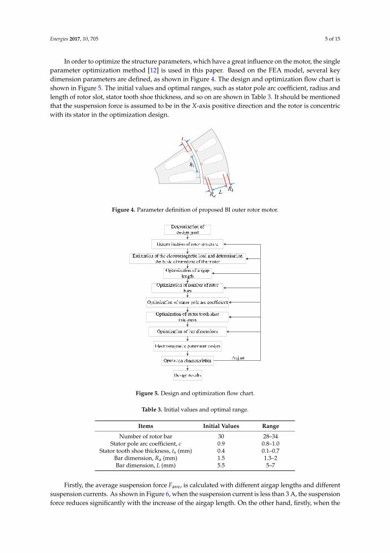
Figures 17–20 show the relationship between f (xi)min and the optimization variables. So, as shownin Table 4, the rotor bar number is selected to be 34, the stator tooth shoe thickness is selected to be0.35 mm, the stator pole arc coefficient is selected to be 0.95, Ra is designed to be 2 mm and L equals6 mm in the proposed motor, respectively.
Energies 2017, 10, 705 9 of 15
In the design of this motor, not only the torque and torque ripple need to be considered, but also the suspension force and suspension force ripple need to be taken into account. When the rotor rotates at high speed, the suspension force generated by the motor will be able to overcome the gravity of the rotor. The ripple of suspension force decides the complexity of suspension force control algorithm. If the suspension force ripple were reduced sufficiently in motor design stage, the motor control algorithm will be greatly simplified and the stability of motor operation will be improved. Therefore, torque, torque ripple, suspension force, suspension force ripple are the four goals of our first choice optimization.
Once the four optimization objectives are determined, the corresponding optimization model f(xi)min can be proposed. As presented in (6), f(xi)min is considered as a weighted sum of each optimization objective [13]. Generally, the optimization design needs to obey some constraints. In this paper, the motor is required to produce a 55 N suspension force at least. As aforementioned in Table 1, the power of the designed motor is more than 1.5 kW and the rated speed is 15,000 r/min. Based on the design requirements, the optimization model can be presented as:
out mini min 1 1 1 rip 2 2 2 rip
ave ave
( ) λ α β λ α β
= + + +
T Ff x T F
T F (6)
i i
i
i
i i
i
i
i i i
( )max ( )min( )rip
( )
( )max ( )min( )rip
( )ave
min max , 1,2,3,......
100%
100%
x xx
x ave
x xx
x
x x x i n
T TT
T
F FF
F
≤ ≤ =−
= ×
−= ×
(7)
where Tout = 1 Nm, Fmin = 55 N, xi means the design variables, λ1 and λ2 are the weight coefficients of torque and suspension force, which satisfy the equation of λ1 + λ2 = 1, α1 and β1 are the weight coefficients of torque and torque ripple in the section of torque optimization, which satisfy the equation of α1 + β1 = 1, α2 and β2 are the weight coefficients of suspension force and suspension force ripple in the section of suspension force optimization, which satisfy α2 + β2 = 1. It is noted that, there are six weight coefficients of λ1, λ2, α1, β1, α2 and β2 in (6), and such weight coefficients usually represent the importance of optimization objectives. Generally, the choice of weight factors is always a key point in the process of multi-objective optimization [14,15]. However, there is not a single standard to determine the values of weight coefficients. In this paper, considering the same importance of the torque and suspension parts, the value of λ1 and λ2 are both selected to be 0.5. According to the design experience of conventional motors and the basic characteristics of bearingless motors, the weight factors of α1, β1, α2 and β2 are selected to be 0.4, 0.6, 0.4 and 0.6, respectively.
Figures 17–20 show the relationship between f(xi)min and the optimization variables. So, as shown in Table 4, the rotor bar number is selected to be 34, the stator tooth shoe thickness is selected to be 0.35 mm, the stator pole arc coefficient is selected to be 0.95, Ra is designed to be 2 mm and L equals 6 mm in the proposed motor, respectively.
Figure 17. f(xi)min versus rotor bar number. Figure 17. f (xi)min versus rotor bar number.
Energies 2017, 10, 705 10 of 15Energies 2017, 10, 705 10 of 15
Figure 18. f(xi)min versus stator pole arc coefficient.
Figure 19. f(xi)min versus stator tooth shoe thickness.
Figure 20. f(xi)min versus bar dimensions.
Table 4. Initial values and optimal values.
Items Initial Values Optimal Values Number of rotor bar 30 34
Stator pole arc coefficient, c 0.9 0.95 Stator tooth shoe thickness, ts (mm) 0.4 0.35
Bar dimension, Ra (mm) 1.5 2 Bar dimension, L (mm) 5.5 6
4. Electromagnetic Performance Analysis
According to the aforementioned design procedure, the dimension parameters of the 3-phase BI motor with outer rotor can be obtained, and the corresponding key parameters are listed in Table 5. Then the electromagnetic performances of the designed motor can be calculated by using the FEA. In the FEA process, silicon steel M470-50A is adopted for the stator and rotor iron cores and the material of rotor bar is aluminum.
0.5
0.6
0.7
0.8
0.9
1
0.8 0.85 0.9 0.95 1Stator pole arc coefficient
0.5
0.55
0.6
0.65
0.7
0.75
0.1 0.2 0.3 0.4 0.5 0.6 0.7Stator tooth shoe thickness
Figure 18. f (xi)min versus stator pole arc coefficient.
Energies 2017, 10, 705 10 of 15
Figure 18. f(xi)min versus stator pole arc coefficient.
Figure 19. f(xi)min versus stator tooth shoe thickness.
Figure 20. f(xi)min versus bar dimensions.
Table 4. Initial values and optimal values.
Items Initial Values Optimal Values Number of rotor bar 30 34
Stator pole arc coefficient, c 0.9 0.95 Stator tooth shoe thickness, ts (mm) 0.4 0.35
Bar dimension, Ra (mm) 1.5 2 Bar dimension, L (mm) 5.5 6
4. Electromagnetic Performance Analysis
According to the aforementioned design procedure, the dimension parameters of the 3-phase BI motor with outer rotor can be obtained, and the corresponding key parameters are listed in Table 5. Then the electromagnetic performances of the designed motor can be calculated by using the FEA. In the FEA process, silicon steel M470-50A is adopted for the stator and rotor iron cores and the material of rotor bar is aluminum.
0.5
0.6
0.7
0.8
0.9
1
0.8 0.85 0.9 0.95 1Stator pole arc coefficient
0.5
0.55
0.6
0.65
0.7
0.75
0.1 0.2 0.3 0.4 0.5 0.6 0.7Stator tooth shoe thickness
Figure 19. f (xi)min versus stator tooth shoe thickness.
Energies 2017, 10, 705 10 of 15
Figure 18. f(xi)min versus stator pole arc coefficient.
Figure 19. f(xi)min versus stator tooth shoe thickness.
Figure 20. f(xi)min versus bar dimensions.
Table 4. Initial values and optimal values.
Items Initial Values Optimal Values Number of rotor bar 30 34
Stator pole arc coefficient, c 0.9 0.95 Stator tooth shoe thickness, ts (mm) 0.4 0.35
Bar dimension, Ra (mm) 1.5 2 Bar dimension, L (mm) 5.5 6
4. Electromagnetic Performance Analysis
According to the aforementioned design procedure, the dimension parameters of the 3-phase BI motor with outer rotor can be obtained, and the corresponding key parameters are listed in Table 5. Then the electromagnetic performances of the designed motor can be calculated by using the FEA. In the FEA process, silicon steel M470-50A is adopted for the stator and rotor iron cores and the material of rotor bar is aluminum.
0.5
0.6
0.7
0.8
0.9
1
0.8 0.85 0.9 0.95 1Stator pole arc coefficient
0.5
0.55
0.6
0.65
0.7
0.75
0.1 0.2 0.3 0.4 0.5 0.6 0.7Stator tooth shoe thickness
Figure 20. f (xi)min versus bar dimensions.
Table 4. Initial values and optimal values.
Items Initial Values Optimal Values
Number of rotor bar 30 34Stator pole arc coefficient, c 0.9 0.95
Stator tooth shoe thickness, ts (mm) 0.4 0.35Bar dimension, Ra (mm) 1.5 2Bar dimension, L (mm) 5.5 6
4. Electromagnetic Performance Analysis
According to the aforementioned design procedure, the dimension parameters of the 3-phase BImotor with outer rotor can be obtained, and the corresponding key parameters are listed in Table 5.Then the electromagnetic performances of the designed motor can be calculated by using the FEA.In the FEA process, silicon steel M470-50A is adopted for the stator and rotor iron cores and thematerial of rotor bar is aluminum.

Energies 2017, 10, 705 11 of 15
Table 5. Key parameters of proposed BI outer rotor motor.
Items Values
TW pole-pair number, Pt 2SW pole-pair number, Ps 1Number of stator slot, Z 24
Number of rotor bar 34Stator outer diameter, Ds (mm) 76
Stack length, la (mm) 70Rotor outer diameter, Dr (mm) 114
Airgap, g0 (mm) 0.3Rated current of TW, is (A) 2.5Rated current of SW, it (A) 2
Stator tooth shoe thickness, ts (mm) 0.35Stator pole arc coefficient, c 0.95
Bar dimension, Ra (mm) 2Bar dimension, L (mm) 6
Figure 21 shows the suspension force and torque output waveforms when the rated currentsare fed into the torque and SWs and the rotor is concentric with its stator. It can be seen that theaverage suspension force is 176 N and the suspension force ripple is 7.75%. In addition, the averagetorque is 1.1 Nm and torque ripple is 8.45%. Figure 22 shows the average suspension force variationwaveforms with respect to the suspension current, when the torque current is equal to 2 A, 2.5 A and3 A, respectively. It can be seen that the average suspension force is proportional to the suspensioncurrent, so it can be concluded that the suspension force can be controlled by adjusting the suspensioncurrent easily, which is consistent with (3). In addition, Figure 22 also describes the average torquevariation waveforms with different currents of SW and TW. It shows that the torque increases alongwith torque current and suspension current, respectively, which is consistent with (4).
Energies 2017, 10, 705 11 of 15
Table 5. Key parameters of proposed BI outer rotor motor.
Items ValuesTW pole-pair number, Pt 2 SW pole-pair number, Ps 1 Number of stator slot, Z 24
Number of rotor bar 34 Stator outer diameter, Ds (mm) 76
Stack length, la (mm) 70 Rotor outer diameter, Dr (mm) 114
Airgap, g0 (mm) 0.3 Rated current of TW, is (A) 2.5 Rated current of SW, it (A) 2
Stator tooth shoe thickness, ts (mm) 0.35 Stator pole arc coefficient, c 0.95
Bar dimension, Ra (mm) 2 Bar dimension, L (mm) 6
Figure 21 shows the suspension force and torque output waveforms when the rated currents are fed into the torque and SWs and the rotor is concentric with its stator. It can be seen that the average suspension force is 176 N and the suspension force ripple is 7.75%. In addition, the average torque is 1.1 Nm and torque ripple is 8.45%. Figure 22 shows the average suspension force variation waveforms with respect to the suspension current, when the torque current is equal to 2 A, 2.5 A and 3 A, respectively. It can be seen that the average suspension force is proportional to the suspension current, so it can be concluded that the suspension force can be controlled by adjusting the suspension current easily, which is consistent with (3). In addition, Figure 22 also describes the average torque variation waveforms with different currents of SW and TW. It shows that the torque increases along with torque current and suspension current, respectively, which is consistent with (4).
Figure 21. Waveforms of rated suspension force and torque.
Figure 22. Fave and Tave versus suspension current and torque current.
Figure 23 shows the suspension force components of Fx and Fy when the rated currents are fed into the torque and SWs with different current phase θ, θ = λ − μ. It can be seen that the suspension force component of Fx is a cosine curve and the amplitude is 176 N. On the other hand, the suspension force component of Fy is a sine curve and the amplitude is also 176 N. So, Fx and Fy are basically consistent
Time (s)
0.4
0.8
1.2
1.6
0
50
100
150
200
0.2 0.225 0.25 0.275 0.3
TorqueSuspension force
The current of SW (A)
0.6
0.9
1.2
1.5
1.8
0
90
180
270
360
450
540
0 1 2 3 4 5
Fave, (It = 2A)Fave, (It = 2.5A)Fave, (It = 3A)
Tave, (It = 2A)Tave, (It = 2.5A)Tave, (It = 3A)
Figure 21. Waveforms of rated suspension force and torque.
Energies 2017, 10, 705 11 of 15
Table 5. Key parameters of proposed BI outer rotor motor.
Items ValuesTW pole-pair number, Pt 2 SW pole-pair number, Ps 1 Number of stator slot, Z 24
Number of rotor bar 34 Stator outer diameter, Ds (mm) 76
Stack length, la (mm) 70 Rotor outer diameter, Dr (mm) 114
Airgap, g0 (mm) 0.3 Rated current of TW, is (A) 2.5 Rated current of SW, it (A) 2
Stator tooth shoe thickness, ts (mm) 0.35 Stator pole arc coefficient, c 0.95
Bar dimension, Ra (mm) 2 Bar dimension, L (mm) 6
Figure 21 shows the suspension force and torque output waveforms when the rated currents are fed into the torque and SWs and the rotor is concentric with its stator. It can be seen that the average suspension force is 176 N and the suspension force ripple is 7.75%. In addition, the average torque is 1.1 Nm and torque ripple is 8.45%. Figure 22 shows the average suspension force variation waveforms with respect to the suspension current, when the torque current is equal to 2 A, 2.5 A and 3 A, respectively. It can be seen that the average suspension force is proportional to the suspension current, so it can be concluded that the suspension force can be controlled by adjusting the suspension current easily, which is consistent with (3). In addition, Figure 22 also describes the average torque variation waveforms with different currents of SW and TW. It shows that the torque increases along with torque current and suspension current, respectively, which is consistent with (4).
Figure 21. Waveforms of rated suspension force and torque.
Figure 22. Fave and Tave versus suspension current and torque current.
Figure 23 shows the suspension force components of Fx and Fy when the rated currents are fed into the torque and SWs with different current phase θ, θ = λ − μ. It can be seen that the suspension force component of Fx is a cosine curve and the amplitude is 176 N. On the other hand, the suspension force component of Fy is a sine curve and the amplitude is also 176 N. So, Fx and Fy are basically consistent
Time (s)
0.4
0.8
1.2
1.6
0
50
100
150
200
0.2 0.225 0.25 0.275 0.3
TorqueSuspension force
The current of SW (A)
0.6
0.9
1.2
1.5
1.8
0
90
180
270
360
450
540
0 1 2 3 4 5
Fave, (It = 2A)Fave, (It = 2.5A)Fave, (It = 3A)
Tave, (It = 2A)Tave, (It = 2.5A)Tave, (It = 3A)
Figure 22. Fave and Tave versus suspension current and torque current.
Figure 23 shows the suspension force components of Fx and Fy when the rated currents are fedinto the torque and SWs with different current phase θ, θ = λ − µ. It can be seen that the suspensionforce component of Fx is a cosine curve and the amplitude is 176 N. On the other hand, the suspensionforce component of Fy is a sine curve and the amplitude is also 176 N. So, Fx and Fy are basically

Energies 2017, 10, 705 12 of 15
consistent with (2). When θ = 0◦, Fx = 176 N, and Fy is small enough to be ignored. Thus the resultantsuspension force basically points to the positive direction of X-axis. So, it can be concluded that theangle between the resultant suspension force and X-axis is equal to –θ, which is consistent with (2).Meanwhile, the relationship between Fx, Fy and the resultant suspension forces Fave with θ can berepresented as shown in Figure 24. It can be found that the direction of resultant suspension forces Fave
can be controlled by adjusting the current phase. In other words, by feeding currents with differentphases into the SW and the TW, a suspension force in any direction can be obtained.
Energies 2017, 10, 705 12 of 15
with (2). When θ = 0°, Fx = 176 N, and Fy is small enough to be ignored. Thus the resultant suspension force basically points to the positive direction of X-axis. So, it can be concluded that the angle between the resultant suspension force and X-axis is equal to –θ, which is consistent with (2). Meanwhile, the relationship between Fx, Fy and the resultant suspension forces Fave with θ can be represented as shown in Figure 24. It can be found that the direction of resultant suspension forces Fave can be controlled by adjusting the current phase. In other words, by feeding currents with different phases into the SW and the TW, a suspension force in any direction can be obtained.
(a) (b)
Figure 23. Fx and Fy versus current phase. (a) Fx versus current phase (b) Fy versus current phase.
Figure 24. Fx, Fy and Fave versus current phase.
In fact, the rotor will be decentered during motor operation. Therefore, when the rotor is radially decentered by external disturbances, the relationships between the radial suspension force, the torque and the eccentricity are investigated. Figure 25 shows the relationships between the torque and the rotor eccentricity in X- and Y-axis directions. It can be seen that when the rotor is shifted radially along the X-axis or Y-axis, the torque almost remains unchanged, namely the rotor eccentricity has little effect on the torque.
(a) (b)
Figure 25. Tave versus rotor eccentricity. (a) with eccentricity in X-axis direction; (b) with eccentricity in Y-axis direction.
-200-150-100-50
050
100150200
0 90 180 270 360Current phase,(deg)
-200-150-100-50
050
100150200
0 90 180 270 360Current phase, (deg)
T ave
(Nm
)
Figure 23. Fx and Fy versus current phase. (a) Fx versus current phase (b) Fy versus current phase.
Energies 2017, 10, 705 12 of 15
with (2). When θ = 0°, Fx = 176 N, and Fy is small enough to be ignored. Thus the resultant suspension force basically points to the positive direction of X-axis. So, it can be concluded that the angle between the resultant suspension force and X-axis is equal to –θ, which is consistent with (2). Meanwhile, the relationship between Fx, Fy and the resultant suspension forces Fave with θ can be represented as shown in Figure 24. It can be found that the direction of resultant suspension forces Fave can be controlled by adjusting the current phase. In other words, by feeding currents with different phases into the SW and the TW, a suspension force in any direction can be obtained.
(a) (b)
Figure 23. Fx and Fy versus current phase. (a) Fx versus current phase (b) Fy versus current phase.
Figure 24. Fx, Fy and Fave versus current phase.
In fact, the rotor will be decentered during motor operation. Therefore, when the rotor is radially decentered by external disturbances, the relationships between the radial suspension force, the torque and the eccentricity are investigated. Figure 25 shows the relationships between the torque and the rotor eccentricity in X- and Y-axis directions. It can be seen that when the rotor is shifted radially along the X-axis or Y-axis, the torque almost remains unchanged, namely the rotor eccentricity has little effect on the torque.
(a) (b)
Figure 25. Tave versus rotor eccentricity. (a) with eccentricity in X-axis direction; (b) with eccentricity in Y-axis direction.
-200-150-100-50
050
100150200
0 90 180 270 360Current phase,(deg)
-200-150-100-50
050
100150200
0 90 180 270 360Current phase, (deg)
T ave
(Nm
)
Figure 24. Fx, Fy and Fave versus current phase.
In fact, the rotor will be decentered during motor operation. Therefore, when the rotor is radiallydecentered by external disturbances, the relationships between the radial suspension force, the torqueand the eccentricity are investigated. Figure 25 shows the relationships between the torque and therotor eccentricity in X- and Y-axis directions. It can be seen that when the rotor is shifted radially alongthe X-axis or Y-axis, the torque almost remains unchanged, namely the rotor eccentricity has littleeffect on the torque.
Energies 2017, 10, 705 12 of 15
with (2). When θ = 0°, Fx = 176 N, and Fy is small enough to be ignored. Thus the resultant suspension force basically points to the positive direction of X-axis. So, it can be concluded that the angle between the resultant suspension force and X-axis is equal to –θ, which is consistent with (2). Meanwhile, the relationship between Fx, Fy and the resultant suspension forces Fave with θ can be represented as shown in Figure 24. It can be found that the direction of resultant suspension forces Fave can be controlled by adjusting the current phase. In other words, by feeding currents with different phases into the SW and the TW, a suspension force in any direction can be obtained.
(a) (b)
Figure 23. Fx and Fy versus current phase. (a) Fx versus current phase (b) Fy versus current phase.
Figure 24. Fx, Fy and Fave versus current phase.
In fact, the rotor will be decentered during motor operation. Therefore, when the rotor is radially decentered by external disturbances, the relationships between the radial suspension force, the torque and the eccentricity are investigated. Figure 25 shows the relationships between the torque and the rotor eccentricity in X- and Y-axis directions. It can be seen that when the rotor is shifted radially along the X-axis or Y-axis, the torque almost remains unchanged, namely the rotor eccentricity has little effect on the torque.
(a) (b)
Figure 25. Tave versus rotor eccentricity. (a) with eccentricity in X-axis direction; (b) with eccentricity in Y-axis direction.
-200-150-100-50
050
100150200
0 90 180 270 360Current phase,(deg)
-200-150-100-50
050
100150200
0 90 180 270 360Current phase, (deg)
T ave
(Nm
)
Figure 25. Tave versus rotor eccentricity. (a) with eccentricity in X-axis direction; (b) with eccentricityin Y-axis direction.

Energies 2017, 10, 705 13 of 15
Figure 26 shows the radial suspension force components and Figure 27 shows the resultantsuspension force Fave with different eccentricities in Y-axis direction. When the rated current is fed intoboth TW and SW with θ = 0◦ at rotor concentric position, the radial suspension force is Fx = 176 N andthe resultant suspension force basically points to the positive direction of X-axis. However, a unilateralmagnetic pull force will be produced in condition of rotor eccentricity [9]. As shown in Figure 26,when the rotor is shifted along the Y-axis, the radial suspension force in the Y-axis direction changesobviously because the motor airgap length in Y-axis is changed greatly. In addition, the amplitudeof Fy is basically symmetrical with increasing rotor eccentricity y in different directions of Y-axis.The relationship between the radial suspension force Fy and the eccentric displacement y is closeto linear. However, the amplitude of Fx changes in a very small range due the unchanged motorairgap length in X-axis direction. And the amplitude of Fx with the rotor eccentricity in Y-axis positivedirection is slightly higher than that in the negative direction. So, the resultant suspension force Fave isnot symmetrical as shown in Figure 27.
Energies 2017, 10, 705 13 of 15
Figure 26 shows the radial suspension force components and Figure 27 shows the resultant suspension force Fave with different eccentricities in Y-axis direction. When the rated current is fed into both TW and SW with θ = 0° at rotor concentric position, the radial suspension force is Fx = 176 N and the resultant suspension force basically points to the positive direction of X-axis. However, a unilateral magnetic pull force will be produced in condition of rotor eccentricity [9]. As shown in Figure 26, when the rotor is shifted along the Y-axis, the radial suspension force in the Y-axis direction changes obviously because the motor airgap length in Y-axis is changed greatly. In addition, the amplitude of Fy is basically symmetrical with increasing rotor eccentricity y in different directions of Y-axis. The relationship between the radial suspension force Fy and the eccentric displacement y is close to linear. However, the amplitude of Fx changes in a very small range due the unchanged motor airgap length in X-axis direction. And the amplitude of Fx with the rotor eccentricity in Y-axis positive direction is slightly higher than that in the negative direction. So, the resultant suspension force Fave is not symmetrical as shown in Figure 27.
Figure 26. Suspension force versus rotor eccentricity in Y-axis direction.
Figure 27. Fave versus rotor eccentricity in Y-axis direction.
Figure 28 shows the radial suspension force components and Figure 29 shows the resultant suspension force Fave with different eccentricities in X-axis direction. As can be seen from Figure 28, when the rotor is shifted along the X-axis, the radial suspension force in the X-axis direction is changed greatly. In addition, according to Equation (5), when the rotor is shifted towards the negative direction of X-axis, the radial force generated by the SW current is gradually offset by the unilateral magnetic pull force due to rotor eccentricity. So, with the increase of rotor eccentricity x in X-axis negative direction, the amplitude of Fx gradually decreases firstly, and then increases slowly in opposite direction due to the increasing unilateral magnetic pull force. When the rotor is shifted towards the positive direction of the X-axis, the radial force generated by the SW current is superimposed on the unilateral magnetic pull force caused by the rotor eccentricity. So the amplitude of Fx increases with increasing rotor eccentricity monotonously. As a result, the resultant suspension force Fave gradually decreases firstly and then increases slowly, as shown in Figure 29.
Fav
e(N
)
Figure 26. Suspension force versus rotor eccentricity in Y-axis direction.
Energies 2017, 10, 705 13 of 15
Figure 26 shows the radial suspension force components and Figure 27 shows the resultant suspension force Fave with different eccentricities in Y-axis direction. When the rated current is fed into both TW and SW with θ = 0° at rotor concentric position, the radial suspension force is Fx = 176 N and the resultant suspension force basically points to the positive direction of X-axis. However, a unilateral magnetic pull force will be produced in condition of rotor eccentricity [9]. As shown in Figure 26, when the rotor is shifted along the Y-axis, the radial suspension force in the Y-axis direction changes obviously because the motor airgap length in Y-axis is changed greatly. In addition, the amplitude of Fy is basically symmetrical with increasing rotor eccentricity y in different directions of Y-axis. The relationship between the radial suspension force Fy and the eccentric displacement y is close to linear. However, the amplitude of Fx changes in a very small range due the unchanged motor airgap length in X-axis direction. And the amplitude of Fx with the rotor eccentricity in Y-axis positive direction is slightly higher than that in the negative direction. So, the resultant suspension force Fave is not symmetrical as shown in Figure 27.
Figure 26. Suspension force versus rotor eccentricity in Y-axis direction.
Figure 27. Fave versus rotor eccentricity in Y-axis direction.
Figure 28 shows the radial suspension force components and Figure 29 shows the resultant suspension force Fave with different eccentricities in X-axis direction. As can be seen from Figure 28, when the rotor is shifted along the X-axis, the radial suspension force in the X-axis direction is changed greatly. In addition, according to Equation (5), when the rotor is shifted towards the negative direction of X-axis, the radial force generated by the SW current is gradually offset by the unilateral magnetic pull force due to rotor eccentricity. So, with the increase of rotor eccentricity x in X-axis negative direction, the amplitude of Fx gradually decreases firstly, and then increases slowly in opposite direction due to the increasing unilateral magnetic pull force. When the rotor is shifted towards the positive direction of the X-axis, the radial force generated by the SW current is superimposed on the unilateral magnetic pull force caused by the rotor eccentricity. So the amplitude of Fx increases with increasing rotor eccentricity monotonously. As a result, the resultant suspension force Fave gradually decreases firstly and then increases slowly, as shown in Figure 29.
Fav
e(N
)
Figure 27. Fave versus rotor eccentricity in Y-axis direction.
Figure 28 shows the radial suspension force components and Figure 29 shows the resultantsuspension force Fave with different eccentricities in X-axis direction. As can be seen from Figure 28,when the rotor is shifted along the X-axis, the radial suspension force in the X-axis direction is changedgreatly. In addition, according to Equation (5), when the rotor is shifted towards the negative directionof X-axis, the radial force generated by the SW current is gradually offset by the unilateral magnetic pullforce due to rotor eccentricity. So, with the increase of rotor eccentricity x in X-axis negative direction,the amplitude of Fx gradually decreases firstly, and then increases slowly in opposite direction due tothe increasing unilateral magnetic pull force. When the rotor is shifted towards the positive directionof the X-axis, the radial force generated by the SW current is superimposed on the unilateral magneticpull force caused by the rotor eccentricity. So the amplitude of Fx increases with increasing rotoreccentricity monotonously. As a result, the resultant suspension force Fave gradually decreases firstlyand then increases slowly, as shown in Figure 29.

Energies 2017, 10, 705 14 of 15Energies 2017, 10, 705 14 of 15
Figure 28. Suspension force versus rotor eccentricity in X-axis direction.
Figure 29. Fave versus rotor eccentricity in X-axis direction.
In order to ensure a stable operation, the suspension force needs to be high enough to stably support the rotor. On other words, the radial force generated by the SW current can overcome rotor gravity and the unilateral magnetic pull force caused by the rotor eccentricity. In this paper, the motor rotor mass is 5.0 kg and the airgap between the rotating shaft and the auxiliary bearing is 0.12 mm. So, the eccentricity of rotor is limited within 0.12 mm. As can be seen from Figure 28, when the rated currents are fed into both TW and SW with θ = 0° and the rotor shifts −0.12 mm in X-axis direction, Fx reaches 91.6 N in the positive direction of the X-axis. In other words, the suspension force produced by suspension current can overcome the unilateral magnetic pull force caused by rotor eccentricity, and there is still a radial force of 91.6 N that can be used to achieve the rotor suspension. Similarly, combining with Figures 23, 24 and 28 and the symmetry of motor structure, it can be found that when the rated current is fed into both TW and SW with θ = −90°, and the rotor reaches −0.12 mm in Y-axis direction, FY is 91.6 N. Considering the rotor weight of 5.0 kg, there is a radial force of 41.6 N that can be used to pull the rotor back to the balance position. Therefore, the motor designed in this paper can be suspended in the case of rotor eccentricity.
5. Conclusions
In this paper, a BI motor with outer rotor has been designed and analyzed. Firstly, the configuration of the BI motor is presented and its torque and suspension force production mechanisms are discussed. In order to obtain the maximum torque and suspension force and the minimum torque ripple and suspension force ripple, several key parameters are optimally designed by using the FEA. The results of FEA show that the suspension force depends strongly on the airgap. The stator pole arc coefficient and the stator pole shoe thickness have little influence on the suspension force, and have an important influence on the torque and torque ripple. In addition, it can be used to optimize the suspension force and torque ripple effectively by selecting the appropriate rotor bar number. Based on the FEA, the electromagnetic performances of the proposed motor with optimal dimensions are calculated and analyzed. When the rated currents are fed into both TW and SW, the suspension force is 176 N and the suspension force ripple is 7.75%. The suspension force is able to overcome the gravity of rotor and the unilateral magnetic pull force caused by rotor eccentricity. At the same time, the average torque is 1.1 Nm and the torque ripple is 8.45%,
Rotor eccentricity in X-axis direction (mm)
Fx
Fy
-200
-100
0
100
200
300
400
500
-0.3 -0.2 -0.1 0 0.1 0.2 0.3F
ave
(N)
Figure 28. Suspension force versus rotor eccentricity in X-axis direction.
Energies 2017, 10, 705 14 of 15
Figure 28. Suspension force versus rotor eccentricity in X-axis direction.
Figure 29. Fave versus rotor eccentricity in X-axis direction.
In order to ensure a stable operation, the suspension force needs to be high enough to stably support the rotor. On other words, the radial force generated by the SW current can overcome rotor gravity and the unilateral magnetic pull force caused by the rotor eccentricity. In this paper, the motor rotor mass is 5.0 kg and the airgap between the rotating shaft and the auxiliary bearing is 0.12 mm. So, the eccentricity of rotor is limited within 0.12 mm. As can be seen from Figure 28, when the rated currents are fed into both TW and SW with θ = 0° and the rotor shifts −0.12 mm in X-axis direction, Fx reaches 91.6 N in the positive direction of the X-axis. In other words, the suspension force produced by suspension current can overcome the unilateral magnetic pull force caused by rotor eccentricity, and there is still a radial force of 91.6 N that can be used to achieve the rotor suspension. Similarly, combining with Figures 23, 24 and 28 and the symmetry of motor structure, it can be found that when the rated current is fed into both TW and SW with θ = −90°, and the rotor reaches −0.12 mm in Y-axis direction, FY is 91.6 N. Considering the rotor weight of 5.0 kg, there is a radial force of 41.6 N that can be used to pull the rotor back to the balance position. Therefore, the motor designed in this paper can be suspended in the case of rotor eccentricity.
5. Conclusions
In this paper, a BI motor with outer rotor has been designed and analyzed. Firstly, the configuration of the BI motor is presented and its torque and suspension force production mechanisms are discussed. In order to obtain the maximum torque and suspension force and the minimum torque ripple and suspension force ripple, several key parameters are optimally designed by using the FEA. The results of FEA show that the suspension force depends strongly on the airgap. The stator pole arc coefficient and the stator pole shoe thickness have little influence on the suspension force, and have an important influence on the torque and torque ripple. In addition, it can be used to optimize the suspension force and torque ripple effectively by selecting the appropriate rotor bar number. Based on the FEA, the electromagnetic performances of the proposed motor with optimal dimensions are calculated and analyzed. When the rated currents are fed into both TW and SW, the suspension force is 176 N and the suspension force ripple is 7.75%. The suspension force is able to overcome the gravity of rotor and the unilateral magnetic pull force caused by rotor eccentricity. At the same time, the average torque is 1.1 Nm and the torque ripple is 8.45%,
Rotor eccentricity in X-axis direction (mm)
Fx
Fy
-200
-100
0
100
200
300
400
500
-0.3 -0.2 -0.1 0 0.1 0.2 0.3F
ave
(N)
Figure 29. Fave versus rotor eccentricity in X-axis direction.
In order to ensure a stable operation, the suspension force needs to be high enough to stablysupport the rotor. On other words, the radial force generated by the SW current can overcome rotorgravity and the unilateral magnetic pull force caused by the rotor eccentricity. In this paper, the motorrotor mass is 5.0 kg and the airgap between the rotating shaft and the auxiliary bearing is 0.12 mm.So, the eccentricity of rotor is limited within 0.12 mm. As can be seen from Figure 28, when the ratedcurrents are fed into both TW and SW with θ = 0◦ and the rotor shifts −0.12 mm in X-axis direction,Fx reaches 91.6 N in the positive direction of the X-axis. In other words, the suspension force producedby suspension current can overcome the unilateral magnetic pull force caused by rotor eccentricity,and there is still a radial force of 91.6 N that can be used to achieve the rotor suspension. Similarly,combining with Figures 23, 24 and 28 and the symmetry of motor structure, it can be found that whenthe rated current is fed into both TW and SW with θ = −90◦, and the rotor reaches −0.12 mm in Y-axisdirection, FY is 91.6 N. Considering the rotor weight of 5.0 kg, there is a radial force of 41.6 N that canbe used to pull the rotor back to the balance position. Therefore, the motor designed in this paper canbe suspended in the case of rotor eccentricity.
5. Conclusions
In this paper, a BI motor with outer rotor has been designed and analyzed. Firstly, the configurationof the BI motor is presented and its torque and suspension force production mechanisms are discussed.In order to obtain the maximum torque and suspension force and the minimum torque ripple andsuspension force ripple, several key parameters are optimally designed by using the FEA. The resultsof FEA show that the suspension force depends strongly on the airgap. The stator pole arc coefficientand the stator pole shoe thickness have little influence on the suspension force, and have an importantinfluence on the torque and torque ripple. In addition, it can be used to optimize the suspensionforce and torque ripple effectively by selecting the appropriate rotor bar number. Based on the FEA,the electromagnetic performances of the proposed motor with optimal dimensions are calculated andanalyzed. When the rated currents are fed into both TW and SW, the suspension force is 176 N and thesuspension force ripple is 7.75%. The suspension force is able to overcome the gravity of rotor and
Energies 2017, 10, 705 15 of 15
the unilateral magnetic pull force caused by rotor eccentricity. At the same time, the average torqueis 1.1 Nm and the torque ripple is 8.45%, which can meet the motor design requirements. Finally,the effect of rotor eccentricity on the torque and suspension force are investigated. As shown in thesimulation results, the torque output is basically unchanged in the case of rotor eccentricity. The rotorradial displacements along the X-axis and Y-axis mainly affect the radial forces in X-axis and Y-axisdirections, respectively. Moreover, in the case of rotor eccentricity, the motor can be suspended stably.
Acknowledgments: This work was sponsored by National Natural Science Foundation of China (51675244),Key Research and Development Project of Jiangsu Province (BE2016150) and the grant from the Priority AcademicProgram Development of Jiangsu Higher Education Institution.
Author Contributions: All authors contributed to this work by collaboration. Yuxin Sun, Jingwei Tang andKai Shi are the main authors of this manuscript.
Conflicts of Interest: The authors declare no conflict of interest.
References
1. Gerada, D.; Mebarki, A.; Brown, N.L.; Gerada, C. High-speed electrical machines: Technologies, trends,and developments. IEEE Trans. Ind. Electron. 2014, 61, 2946–2959. [CrossRef]
2. He, Y.; Nian, H. Analytical model and feedback control of the suspension force for an induction typebearingless motor. IEEE Proc. PEDS 2003, 1, 242–246. [CrossRef]
3. Bu, W.; Huang, S.; Wan, S.; Liu, W. General analytical models of inductance matrices of four-pole bearinglessmotors with two-pole controlling windings. IEEE Trans. Magn. 2009, 45, 3316–3321. [CrossRef]
4. Reichert, T.; Nussbaumer, T.; Gruber, W.; Kolar, J.W. Bearingless permanent-magnet motor with 4/12 slot-poleratio for bioreactor stirring applications. IEEE/ASME Trans. Mechatron. 2011, 16, 431–439. [CrossRef]
5. Li, W.; Chau, K.T.; Ching, T.W.; Wang, Y.; Chen, M. Design of a high-speed superconducting bearinglessmachine for flywheel energy storage systems. IEEE Trans. Appl. Supercond. 2015, 25, 5700204. [CrossRef]
6. Cao, X.; Deng, Z. A full-period generating mode for bearingless switched reluctance generators. IEEE Trans.Appl. Supercond. 2010, 20, 1072–1076. [CrossRef]
7. Chiba, A.; Asama, J. Influence of rotor skew in induction type bearingless motor. IEEE Trans. Magn. 2012, 48,4646–4649. [CrossRef]
8. Ferreira, J.M.S.; Zucca, M.; Salazar, A.O.; Donadio, L. Analysis of a bearingless machine with dividedwindings. IEEE Trans. Magn. 2005, 41, 3931–3933. [CrossRef]
9. Schoeb, R.; Bichsel, J. Vector control of the bearingless motor. In Proceedings of the International Symposiumon Magnetic Bearings (ISMB), ETH Zurich, Zürich, Switzerland, 23–26 August 1994.
10. Pyrhoenen, J.; Jokinen, T.; Hrabovcova, V. Design of Rotating Electrical Machines; John Wiley & Sons: New Dehli,India, 2013; ISBN: 9780470695166.
11. Zheng, P.; Liu, R.; Thelin, P.; Nordlund, E. Research on the cooling system of a 4QT prototype machine usedfor HEV. IEEE Trans. Energy Convers. 2008, 50, 61–67. [CrossRef]
12. Lei, G.; Wang, T.; Guo, Y.; Zhu, J. System-level design optimization methods for electrical drive systems:Deterministic approach. IEEE Trans. Ind. Electron. 2014, 61, 6591–6602. [CrossRef]
13. Zhu, X.; Shu, Z.; Quan, L.; Xiang, Z. Multi-objective optimization of an outer-rotor V-shaped permanentmagnet flux switching motor based on multi-level design method. IEEE Trans. Magn. 2016, 52, 8205508.[CrossRef]
14. Lei, G.; Liu, C.; Zhu, J.; Guo, Y. Techniques for multilevel design optimization of permanent magnet motors.IEEE Trans. Energy Convers. 2015, 30, 1574–1584. [CrossRef]
15. Lei, G.; Xu, W.; Hu, J.; Zhu, J. Multilevel design optimization of a FSPMM drive system by using sequentialsubspace optimization method. IEEE Trans. Magn. 2014, 50, 685–688. [CrossRef]
© 2017 by the authors. Licensee MDPI, Basel, Switzerland. This article is an open accessarticle distributed under the terms and conditions of the Creative Commons Attribution(CC BY) license (http://creativecommons.org/licenses/by/4.0/).