Loss Investigation of Slotless Bearingless Disk Drives · Loss Investigation of Slotless...
8
© 2015 IEEE Proceedings of the IEEE Energy Conversion Congress & Expo (ECCE USA 2015), Montreal, Canada, September 20-24, 2015 Loss Investigation of Slotless Bearingless Disk Drives D. Steinert, I. Kovacevic-Badstübner, T. Nussbaumer, J. W. Kolar This material is published in order to provide access to research results of the Power Electronic Systems Laboratory / D-ITET / ETH Zurich. Internal or personal use of this material is permitted. However, permission to reprint/republish this material for advertising or promotional purposes or for creating new collective works for resale or redistribution must be obtained from the copyright holder. By choosing to view this document, you agree to all provisions of the copyright laws protecting it.
Transcript of Loss Investigation of Slotless Bearingless Disk Drives · Loss Investigation of Slotless...
© 2015 IEEE
Proceedings of the IEEE Energy Conversion Congress & Expo (ECCE USA 2015), Montreal, Canada, September 20-24, 2015
Loss Investigation of Slotless Bearingless Disk Drives
D. Steinert,I. Kovacevic-Badstübner,T. Nussbaumer,J. W. Kolar
This material is published in order to provide access to research results of the Power Electronic Systems Laboratory / D-ITET / ETH Zurich. Internal or personal use of this material is permitted. However, permission to reprint/republish this material for advertising or promotional purposes or for creating new collective works for resale or redistribution must be obtained from the copyright holder. By choosing to view this document, you agree to all provisions of the copyright laws protecting it.
Loss Investigation of Slotless BearinglessDisk Drives
Daniel Steinert∗, Ivana Kovacevic-Badstubner∗, Thomas Nussbaumer†, Johann W. Kolar∗∗Power Electronic Systems Laboratory, ETH Zurich, Switzerland, Email: [email protected]
†Levitronix GmbH, 8005 Zurich, Switzerland, Email: [email protected]
Abstract—Losses are often a limiting factor for the applicationof bearingless motors, especially at high rotational speeds. Inthis paper the loss mechanisms in slotless bearingless disk driveswith toroidal windings are identified and analyzed. Althoughthe slotless topology already features comparably low losses, adetailed comprehensive analysis of the loss portion enables afurther reduction of these losses. To obtain the loss composition,computationally efficient simulation and calculation methods aswell as simple measurement methods are presented for each losscomponent, considering iron losses, eddy current losses in thecoils, PWM induced losses, copper losses, windage losses, andinverter losses. This allows for optimization of the motor geometrytowards minimized losses. The analysis results are compared withloss measurements of four different motors with different rotorsizes, pole pair numbers, and coil configurations.
Keywords—iron loss, loss composition, bearingless slice motor,magnetic levitation.
I. INTRODUCTION
In a bearingless motor — also called self-bearing motor —the rotor is levitated magnetically in the middle of the statorwithout any mechanical contact, where motor and bearingfunctionality are integrated into one magnetic circuit [1]. Dueto the absence of lubrication and abrasion, this motors canbe used, for example, in vacuum applications, high speedapplications [2], [3], or in applications with high demandson purity or chemical resistance, as they exist in pumps andmixers [4]–[6]. However, bearingless motors often have highelectromagnetic losses – especially at high speeds – which isdue to the big air gap and the high magnetic fields needed forthe magnetic bearing. Especially at the teeth in most of thetopologies, the high spatial field harmonics induce high eddycurrent and hysteresis losses in the stator iron and eddy currentlosses in the conductive parts of the rotor. This is one of themost critical drawbacks of bearingless motors, as it limits theachievable power densities and rotational speeds needed formany applications. Therefore, the topologies investigated inthis paper consist of a slotless ring-shaped stator, as they arepresented in [7]–[9], which results in reduced losses comparedto conventional-type bearingless motors.
To further optimize and reduce the losses, a detailed andcomprehensive analysis of the loss portions of this bearinglessmotor type is conducted in this paper. With particular consider-ation of the motor size and pole pair number, this also enablesthe prediction of the power consumption for various slotlessmotors. The identified loss mechanisms are the iron lossesin the stator iron, eddy current losses in the coils, harmonic
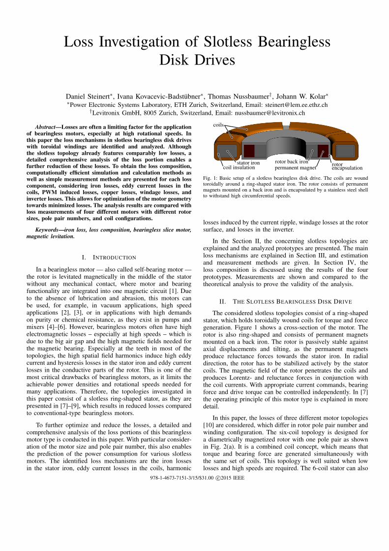
coils
coil insulationstator iron rotor back iron
permanent magnet rotorencapsulation
Fig. 1: Basic setup of a slotless bearingless disk drive. The coils are woundtoroidally around a ring-shaped stator iron. The rotor consists of permanentmagnets mounted on a back iron and is encapsulated by a stainless steel shellto withstand high circumferential speeds.
losses induced by the current ripple, windage losses at the rotorsurface, and losses in the inverter.
In the Section II, the concerning slotless topologies areexplained and the analyzed prototypes are presented. The mainloss mechanisms are explained in Section III, and estimationand measurement methods are given. In Section IV, theloss composition is discussed using the results of the fourprototypes. Measurements are shown and compared to thetheoretical analysis to prove the validity of the analysis.
II. THE SLOTLESS BEARINGLESS DISK DRIVE
The considered slotless topologies consist of a ring-shapedstator, which holds toroidally wound coils for torque and forcegeneration. Figure 1 shows a cross-section of the motor. Therotor is also ring-shaped and consists of permanent magnetsmounted on a back iron. The rotor is passively stable againstaxial displacements and tilting, as the permanent magnetsproduce reluctance forces towards the stator iron. In radialdirection, the rotor has to be stabilized actively by the statorcoils. The magnetic field of the rotor penetrates the coils andproduces Lorentz- and reluctance forces in conjunction withthe coil currents. With appropriate current commands, bearingforce and drive torque can be controlled independently. In [7]the operating principle of this motor type is explained in moredetail.
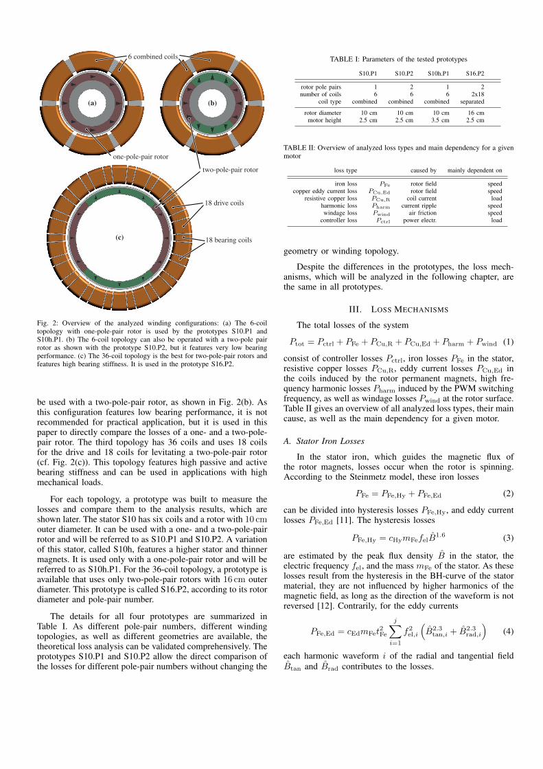
In this paper, the losses of three different motor topologies[10] are considered, which differ in rotor pole pair number andwinding configuration. The six-coil topology is designed fora diametrically magnetized rotor with one pole pair as shownin Fig. 2(a). It is a combined coil concept, which means thattorque and bearing force are generated simultaneously withthe same set of coils. This topology is well suited when lowlosses and high speeds are required. The 6-coil stator can also
978-1-4673-7151-3/15/$31.00 c©2015 IEEE
(a) (b)
(c)
6 combined coils
one-pole-pair rotor
two-pole-pair rotor
18 bearing coils
18 drive coils
Fig. 2: Overview of the analyzed winding configurations: (a) The 6-coiltopology with one-pole-pair rotor is used by the prototypes S10.P1 andS10h.P1. (b) The 6-coil topology can also be operated with a two-pole pairrotor as shown with the prototype S10.P2, but it features very low bearingperformance. (c) The 36-coil topology is the best for two-pole-pair rotors andfeatures high bearing stiffness. It is used in the prototype S16.P2.
be used with a two-pole-pair rotor, as shown in Fig. 2(b). Asthis configuration features low bearing performance, it is notrecommended for practical application, but it is used in thispaper to directly compare the losses of a one- and a two-pole-pair rotor. The third topology has 36 coils and uses 18 coilsfor the drive and 18 coils for levitating a two-pole-pair rotor(cf. Fig. 2(c)). This topology features high passive and activebearing stiffness and can be used in applications with highmechanical loads.
For each topology, a prototype was built to measure thelosses and compare them to the analysis results, which areshown later. The stator S10 has six coils and a rotor with 10 cmouter diameter. It can be used with a one- and a two-pole-pairrotor and will be referred to as S10.P1 and S10.P2. A variationof this stator, called S10h, features a higher stator and thinnermagnets. It is used only with a one-pole-pair rotor and will bereferred to as S10h.P1. For the 36-coil topology, a prototype isavailable that uses only two-pole-pair rotors with 16 cm outerdiameter. This prototype is called S16.P2, according to its rotordiameter and pole-pair number.
The details for all four prototypes are summarized inTable I. As different pole-pair numbers, different windingtopologies, as well as different geometries are available, thetheoretical loss analysis can be validated comprehensively. Theprototypes S10.P1 and S10.P2 allow the direct comparison ofthe losses for different pole-pair numbers without changing the
TABLE I: Parameters of the tested prototypes
S10.P1 S10.P2 S10h.P1 S16.P2
rotor pole pairs 1 2 1 2number of coils 6 6 6 2x18
coil type combined combined combined separated
rotor diameter 10 cm 10 cm 10 cm 16 cmmotor height 2.5 cm 2.5 cm 3.5 cm 2.5 cm
TABLE II: Overview of analyzed loss types and main dependency for a givenmotor
loss type caused by mainly dependent on
iron loss PFe rotor field speedcopper eddy current loss PCu,Ed rotor field speed
resistive copper loss PCu,R coil current loadharmonic loss Pharm current ripple speedwindage loss Pwind air friction speed
controller loss Pctrl power electr. load
geometry or winding topology.
Despite the differences in the prototypes, the loss mech-anisms, which will be analyzed in the following chapter, arethe same in all prototypes.
III. LOSS MECHANISMS
The total losses of the system
Ptot = Pctrl + PFe + PCu,R + PCu,Ed + Pharm + Pwind (1)
consist of controller losses Pctrl, iron losses PFe in the stator,resistive copper losses PCu,R, eddy current losses PCu,Ed inthe coils induced by the rotor permanent magnets, high fre-quency harmonic losses Pharm induced by the PWM switchingfrequency, as well as windage losses Pwind at the rotor surface.Table II gives an overview of all analyzed loss types, their maincause, as well as the main dependency for a given motor.
A. Stator Iron Losses
In the stator iron, which guides the magnetic flux ofthe rotor magnets, losses occur when the rotor is spinning.According to the Steinmetz model, these iron losses
PFe = PFe,Hy + PFe,Ed (2)
can be divided into hysteresis losses PFe,Hy, and eddy currentlosses PFe,Ed [11]. The hysteresis losses
PFe,Hy = cHymFefelB1.6 (3)
are estimated by the peak flux density B in the stator, theelectric frequency fel, and the mass mFe of the stator. As theselosses result from the hysteresis in the BH-curve of the statormaterial, they are not influenced by higher harmonics of themagnetic field, as long as the direction of the waveform is notreversed [12]. Contrarily, for the eddy currents
PFe,Ed = cEdmFet2Fe
j∑i=1
f2el,i
(B2.3
tan,i + B2.3rad,i
)(4)
each harmonic waveform i of the radial and tangential fieldBtan and Brad contributes to the losses.
(T)B
1.78
1.77
1.76
1.75
1.74
stator iron coil
X
rotor
(a) 3D simulation with rotor P1
flux
dens
ity
0 90 180 270 360
B(T
)
-2
-1
0
1
2
(deg)αrotor angle
Brad
Btan
(b) 2D sim. with rotor P1
rotor angle α (deg)
0 90 180 270 360
fluxdensity
B(T
)
-2
-1
0
1
2
(c) 2D sim. with rotor P2
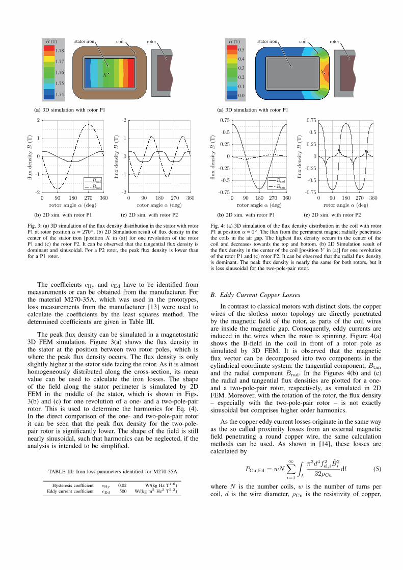
Fig. 3: (a) 3D simulation of the flux density distribution in the stator with rotorP1 at rotor position α = 270◦. (b) 2D Simulation result of flux density in thecenter of the stator iron [position X in (a)] for one revolution of the rotorP1 and (c) the rotor P2. It can be observed that the tangential flux density isdominant and sinusoidal. For a P2 rotor, the peak flux density is lower thanfor a P1 rotor.
The coefficients cHy and cEd have to be identified frommeasurements or can be obtained from the manufacturer. Forthe material M270-35A, which was used in the prototypes,loss measurements from the manufacturer [13] were used tocalculate the coefficients by the least squares method. Thedetermined coefficients are given in Table III.
The peak flux density can be simulated in a magnetostatic3D FEM simulation. Figure 3(a) shows the flux density inthe stator at the position between two rotor poles, which iswhere the peak flux density occurs. The flux density is onlyslightly higher at the stator side facing the rotor. As it is almosthomogeneously distributed along the cross-section, its meanvalue can be used to calculate the iron losses. The shapeof the field along the stator perimeter is simulated by 2DFEM in the middle of the stator, which is shown in Figs.3(b) and (c) for one revolution of a one- and a two-pole-pairrotor. This is used to determine the harmonics for Eq. (4).In the direct comparison of the one- and two-pole-pair rotorit can be seen that the peak flux density for the two-pole-pair rotor is significantly lower. The shape of the field is stillnearly sinusoidal, such that harmonics can be neglected, if theanalysis is intended to be simplified.
TABLE III: Iron loss parameters identified for M270-35A
Hysteresis coefficient cHy 0.02 W/(kg Hz T1.6)Eddy current coefficient cEd 500 W/(kg m2 Hz2 T2.3)
(T)B
0.5
0.0
0.4
0.3
0.2
0.1
stator iron coil rotor
Y
(a) 3D simulation with rotor P1
flux
dens
ityrotor angle α (deg)
0 90 180 270 360-0.75
-0.5
-0.25
0
0.25
0.5
0.75
Brad
Btan
B(T
)(b) 2D sim. with rotor P1
rotor angle α (deg)
0 90 180 270 360
fluxdensity
B(T
)
-0.75
-0.5
-0.25
0
0.25
0.5
0.75
(c) 2D sim. with rotor P2
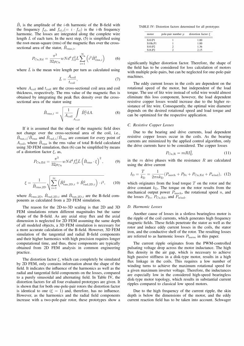
Fig. 4: (a) 3D simulation of the flux density distribution in the coil with rotorP1 at position α = 0◦. The flux from the permanent magnet radially penetratesthe coils in the air gap. The highest flux density occurs in the center of thecoil and decreases towards the top and bottom. (b) 2D Simulation result ofthe flux density in the center of the coil [position Y in (a)] for one revolutionof the rotor P1 and (c) rotor P2. It can be observed that the radial flux densityis dominant. The peak flux density is nearly the same for both rotors, but itis less sinusoidal for the two-pole-pair rotor.
B. Eddy Current Copper Losses
In contrast to classical motors with distinct slots, the copperwires of the slotless motor topology are directly penetratedby the magnetic field of the rotor, as parts of the coil wiresare inside the magnetic gap. Consequently, eddy currents areinduced in the wires when the rotor is spinning. Figure 4(a)shows the B-field in the coil in front of a rotor pole assimulated by 3D FEM. It is observed that the magneticflux vector can be decomposed into two components in thecylindrical coordinate system: the tangential component, Btan
and the radial component Brad. In the Figures 4(b) and (c)the radial and tangential flux densities are plotted for a one-and a two-pole-pair rotor, respectively, as simulated in 2DFEM. Moreover, with the rotation of the rotor, the flux density– especially with the two-pole-pair rotor – is not exactlysinusoidal but comprises higher order harmonics.
As the copper eddy current losses originate in the same wayas the so called proximity losses from an external magneticfield penetrating a round copper wire, the same calculationmethods can be used. As shown in [14], these losses arecalculated by
PCu,Ed = wN∞∑i=1
∫L
π3d4f2el,iB2i
32ρCudl (5)
where N is the number coils, w is the number of turns percoil, d is the wire diameter, ρCu is the resistivity of copper,
Bi is the amplitude of the i-th harmonic of the B-field withthe frequency fel, and fel,i(= i · fel) is the i-th frequencyharmonic. The losses are integrated along the complete wirelength L of each turn. In the next step, (5) is simplified usingthe root-mean-square (rms) of the magnetic flux over the cross-sectional area of the stator, Brms,i,
PCu,Ed =π3
32ρCuwNd4f2elL
∞∑i=1
(i2B2
rms,i
)(6)
where L is the mean wire length per turn as calculated using
L =Acoil
tcoil, (7)
where Acoil and tcoil are the cross-sectional coil area and coilthickness, respectively. The rms value of the magnetic flux isobtained by integrating the peak flux density over the cross-sectional area of the stator using
Brms,i =
√√√√ 1
Acoil
∫Acoil
B2i dA. (8)
If it is assumed that the shape of the magnetic field doesnot change over the cross-sectional area of the coil, i.e.,Btan,i/Brms and Brad,i/Brms are constant for every point ofAcoil, where Brms is the rms value of total B-field calculatedusing 3D FEM simulation, then (6) can be simplified by meansof a distortion factor ξ, as,
PCu,Ed =π3
32ρCuwNd4f2elL
(Brms · ξ
)2, (9)
ξ =1
Brms,2D
√√√√ ∞∑i=1
(B2
tan,2D,i + B2rad,2D,i
)· i2, (10)
where Brms,2D, Brad,2D,i and Btan,2D,i are the B-field com-ponents as calculated from a 2D FEM simulation.
The reason for the 2D-to-3D scaling is that 2D and 3DFEM simulations return different magnitudes but the sameshape of the B-field. As any axial stray flux and the axialdimension is neglected for 2D FEM assuming the same depthof all modeled objects, a 3D FEM simulation is necessary fora more accurate calculation of the B-field. However, 3D FEMsimulation of the tangential and radial B-field componentsand their higher harmonics with high precision requires longercomputational time, and thus, these components are typicallyobtained from 2D FEM analysis in common engineeringpractice.
The distortion factor ξ, which can completely be simulatedby 2D FEM, only contains information about the shape of thefield. It indicates the influence of the harmonics as well as theradial and tangential field components on the losses, comparedto a purely sinusoidal and alternating field. In Table IV, thedistortion factors for all four evaluated prototypes are given. Itis shown that for both one-pole-pair rotors the distortion factoris identical to one (ξ = 1) and, therefore, has no influence.However, as the harmonics and the radial field componentsincrease with a two-pole-pair rotor, these prototypes show a
TABLE IV: Distortion factors determined for all prototypes
motor pole-pair number p distortion factor ξ
S10.P1 1 1.00S10h.P1 1 1.00S10.P2 2 1.36S16.P2 2 2.15
significantly higher distortion factor. Therefore, the shape ofthe field has to be considered for loss calculation of motorswith multiple pole-pairs, but can be neglected for one-pole-pairmachines.
The eddy current losses in the coils are dependent on therotational speed of the motor, but independent of the loadtorque. The use of litz wire instead of solid wire would almosteliminate this loss component, however, the load dependentresistive copper losses would increase due to the higher re-sistance of litz wire. Consequently, the optimal wire diameterdepends on the desired rotational speed and load torque andcan be optimized for the respective application.
C. Resistive Copper Losses
Due to the bearing and drive currents, load dependentresistive copper losses occur in the coils. As the bearingcurrents are minimized by the applied control algorithm, onlythe drive currents have to be considered. The copper losses
PCu,R = mRI2D (11)
in the m drive phases with the resistance R are calculatedusing the drive current
ID =T
kD=
1
2πnkD(Pmech + PFe + PCu,Ed + Pwind), (12)
which originates from the load torque T on the rotor and thedrive constant kD. The torque on the rotor results from themechanical output power Pmech, the rotational speed n, andthe losses PFe, PCu,Ed, and Pwind.
D. Harmonic Losses
Another cause of losses in a slotless bearingless motor isthe ripple of the coil currents, which generates high frequencymagnetic fields. These fields penetrate the stator as well as therotor and induce eddy current losses in the coils, the statoriron, and the conductive shell of the rotor. The resulting lossesare referred to as harmonic losses Pharm in this paper.
The current ripple originates from the PWM-controlledpulsating voltage drop across the motor inductance. The highflux density in the air gap, which is necessary to achievehigh passive stiffness in a disk-type motor, results in a highflux linkage in the coils. This requires a low number ofwinding turns to achieve the maximum rotational speed fora given maximum inverter voltage. Therefore, the inductancesare especially low in the considered high-speed bearinglessdisk-type motor topology, which results in substantial currentripples compared to classical low speed motors.
Due to the high frequency of the current ripple, the skindepth is below the dimensions of the motor, and the eddycurrent reaction field has to be taken into account. Schwager
time (ms)
-1.5 -1 -0.5 0 0.5 1 1.5
coilcurrent(A
)
-1.5
-1
-0.5
0
0.5
1
1.5
(a)
time (ms)
-1.5 -1 -0.5 0 0.5 1 1.5
coilcurrent(A
)
-1.5
-1
-0.5
0
0.5
1
1.5
(b)
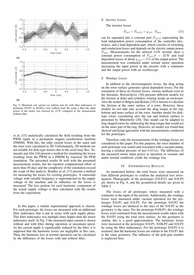
Fig. 5: Measured coil current (a) without and (b) with filter inductance ofprototype S10.P1 at 20 000 r/min without load. By using a filter the inputpower of the motor was lowered by 24W compared to the measurementwithout filter.
et. al. [15] analytically calculated the field resulting from thePWM ripple in a permanent magnet synchronous machine(PMSM). With this, the eddy current losses in the stator andthe rotor were calculated in 2D. Unfortunately, 2D methods arenot reliable for disk-type motors due to the axial stray flux. Ya-mazaki and Abe [16] present a method for simulating the lossesresulting from the PWM in a PMSM by transient 3D FEMsimulation. The presented results fit well with the presentedmeasurement results, but the reported computational effort ofmore than 50 days and the complexity of the simulation exceedthe scope of this analysis. Bradley et. al. [17] present a methodfor measuring the losses for existing prototypes. A sinusoidalvoltage with variable frequency is superimposed on the supplyvoltage of the machine and its influence on the losses ismeasured. The loss portion for each harmonic component ofthe actual supply voltage is then calculated with the resultsfrom the experiment.
In this paper, a similar experimental approach is chosen.For each prototype, the losses are measured with an additionalfilter inductance that is put in series with each supply phase.This filter inductance was multiple times higher than the motorinductance itself. In Fig. 5 the measured input current is shownwithout and with filter during operation at maximum speed.As the current ripple is significantly reduced by the filter, it issupposed that the harmonic losses are negligible in this case.Then, the harmonic loss in normal operation can be calculatedby the difference of the losses with and without filter.
E. Inverter Losses
The inverter losses
Pctrl = Pctrl,0 + χctrl · Pmot (13)
can be separated into a constant part Pctrl,0 representing theload independent power consumption of the controller elec-tronics, and a load dependent part, which consists of switchingand conduction losses and depends on the electric output powerPmot. Measurements for the utilized 2 kW inverter show aconstant power consumption of Pctrl, 0 = 22 W and loaddependent losses of about χctrl = 8 % of the output power. Themeasurement was conducted under normal motor operationmeasuring the input power at the inverter with a wattmeterand the output power with an oscilloscope.
F. Windage Losses
In addition to the electromagnetic losses, the drag actingon the rotor surface generates speed dependent losses. For theestimation of these air friction losses, various methods exist inthe literature. Borisavljevic [18] presents different models forthe friction at disks and cylinders rotating inside an enclosure.Also the model of Bilgen and Bolous [19] is known to calculatethe friction at the outer surface of a rotor. However, thesemodels do not take into account the drag torque at the top,bottom and inner surface of the rotor. Another model for disk-type rotors considering also the top and bottom surface ispresented by Mitterhofer [20]. This model can be adapted toring-shaped rotors by subtracting the drag torque that would acton the inner part of the ring. However, no model was found thatshowed satisfying agreement with the measurements conductedfor the prototypes.
Therefore, only the measurements of the windage losses areconsidered in this paper. For this purpose, the rotor chamber ofeach prototype was sealed and evacuated with a vacuum pump,leaving a residual pressure of just 0.05 bar. The difference ofthe measured motor input power at operation in vacuum andunder normal conditions yields the windage loss.
IV. EXPERIMENTAL RESULTS
As mentioned before, the total losses were measured onfour different prototypes to confirm the analytical loss inves-tigation. Photographs of the prototypes S10.P1/2 and S16.P2are shown in Fig. 6, and the geometrical details are given inTable I.
The losses of all prototypes where measured with awattmeter at the input of the inverter. Additionally, the windagelosses were measured under vacuum operation for the pro-totypes S10.P1 and S16.P2. For the prototype S10.P2 thewindage losses are identical to the ones of the S10.P2 as thegeometry is the same. For the prototype S10h.P1, the windagelosses were estimated from the measurement results taken withthe S10.P1 using the total rotor surface. As the geometry issimilar, this is a good approximation. The harmonic losseswere measured at the prototypes S10.P1, S10h.P2 and S16.P2by using the filter inductances. For the prototype S10.P2 it isassumed, that the harmonic losses are similar to the S10.P1 dueto the same geometry. The influence of the pole-pair numberis neglected here.
one- or two-pole-pair rotor
6 combined coils
(a) prototype S10.P1/P2
two-pole-pair rotor
18 bearing coils
18 drive coils
(b) prototype S16.P2
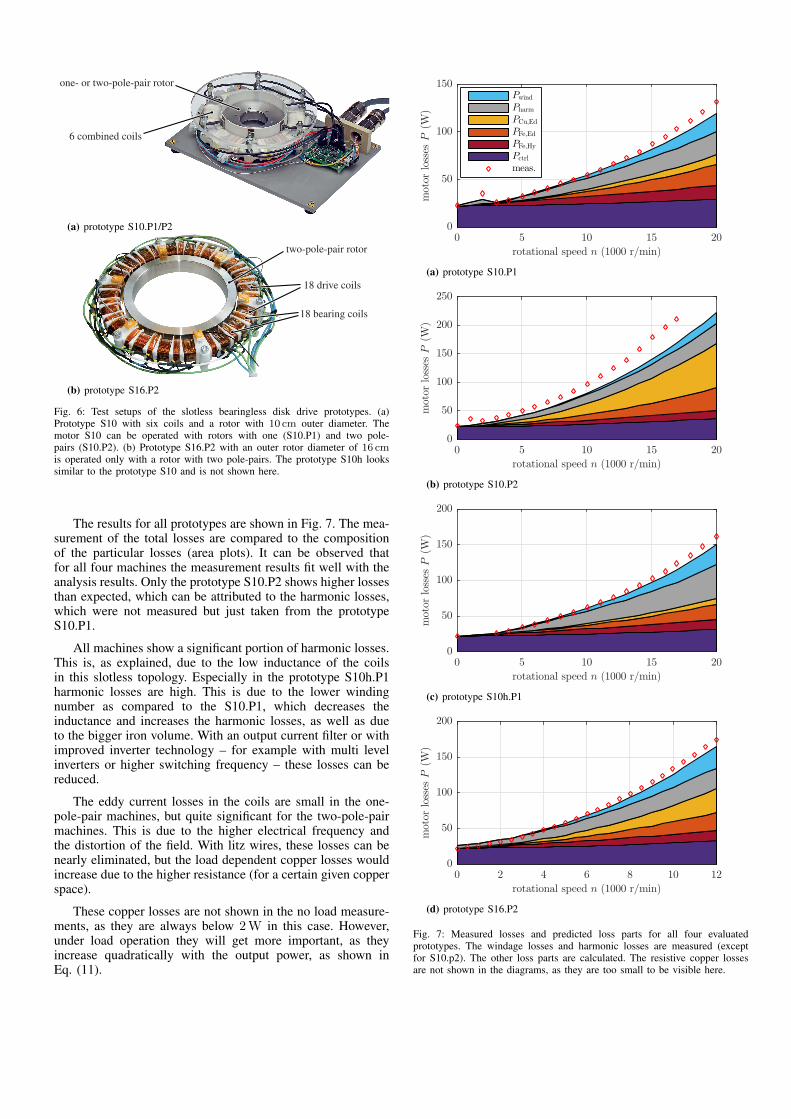
Fig. 6: Test setups of the slotless bearingless disk drive prototypes. (a)Prototype S10 with six coils and a rotor with 10 cm outer diameter. Themotor S10 can be operated with rotors with one (S10.P1) and two pole-pairs (S10.P2). (b) Prototype S16.P2 with an outer rotor diameter of 16 cmis operated only with a rotor with two pole-pairs. The prototype S10h lookssimilar to the prototype S10 and is not shown here.
The results for all prototypes are shown in Fig. 7. The mea-surement of the total losses are compared to the compositionof the particular losses (area plots). It can be observed thatfor all four machines the measurement results fit well with theanalysis results. Only the prototype S10.P2 shows higher lossesthan expected, which can be attributed to the harmonic losses,which were not measured but just taken from the prototypeS10.P1.
All machines show a significant portion of harmonic losses.This is, as explained, due to the low inductance of the coilsin this slotless topology. Especially in the prototype S10h.P1harmonic losses are high. This is due to the lower windingnumber as compared to the S10.P1, which decreases theinductance and increases the harmonic losses, as well as dueto the bigger iron volume. With an output current filter or withimproved inverter technology – for example with multi levelinverters or higher switching frequency – these losses can bereduced.
The eddy current losses in the coils are small in the one-pole-pair machines, but quite significant for the two-pole-pairmachines. This is due to the higher electrical frequency andthe distortion of the field. With litz wires, these losses can benearly eliminated, but the load dependent copper losses wouldincrease due to the higher resistance (for a certain given copperspace).
These copper losses are not shown in the no load measure-ments, as they are always below 2 W in this case. However,under load operation they will get more important, as theyincrease quadratically with the output power, as shown inEq. (11).
rotational speed n (1000 r/min)
0 5 10 15 20
motor
losses
P(W
)
0
50
100
150Pwind
Pharm
PCu,Ed
PFe,Ed
PFe,Hy
Pctrl
meas.
(a) prototype S10.P1
rotational speed n (1000 r/min)
0 5 10 15 20
motor
losses
P(W
)
0
50
100
150
200
250
(b) prototype S10.P2
rotational speed n (1000 r/min)
0 5 10 15 20
motor
losses
P(W
)
0
50
100
150
200
(c) prototype S10h.P1
rotational speed n (1000 r/min)
0 2 4 6 8 10 12
motor
losses
P(W
)
0
50
100
150
200
(d) prototype S16.P2
Fig. 7: Measured losses and predicted loss parts for all four evaluatedprototypes. The windage losses and harmonic losses are measured (exceptfor S10.p2). The other loss parts are calculated. The resistive copper lossesare not shown in the diagrams, as they are too small to be visible here.
rotational speed n (1000 r/min)
0 2 4 6 8 10 12 14 16 18 20
motor
losses
Pmot(W
)
0
25
50
75
100
125
150
175
200
S10.P1
S10.P2
S10h.P1
S16.P2
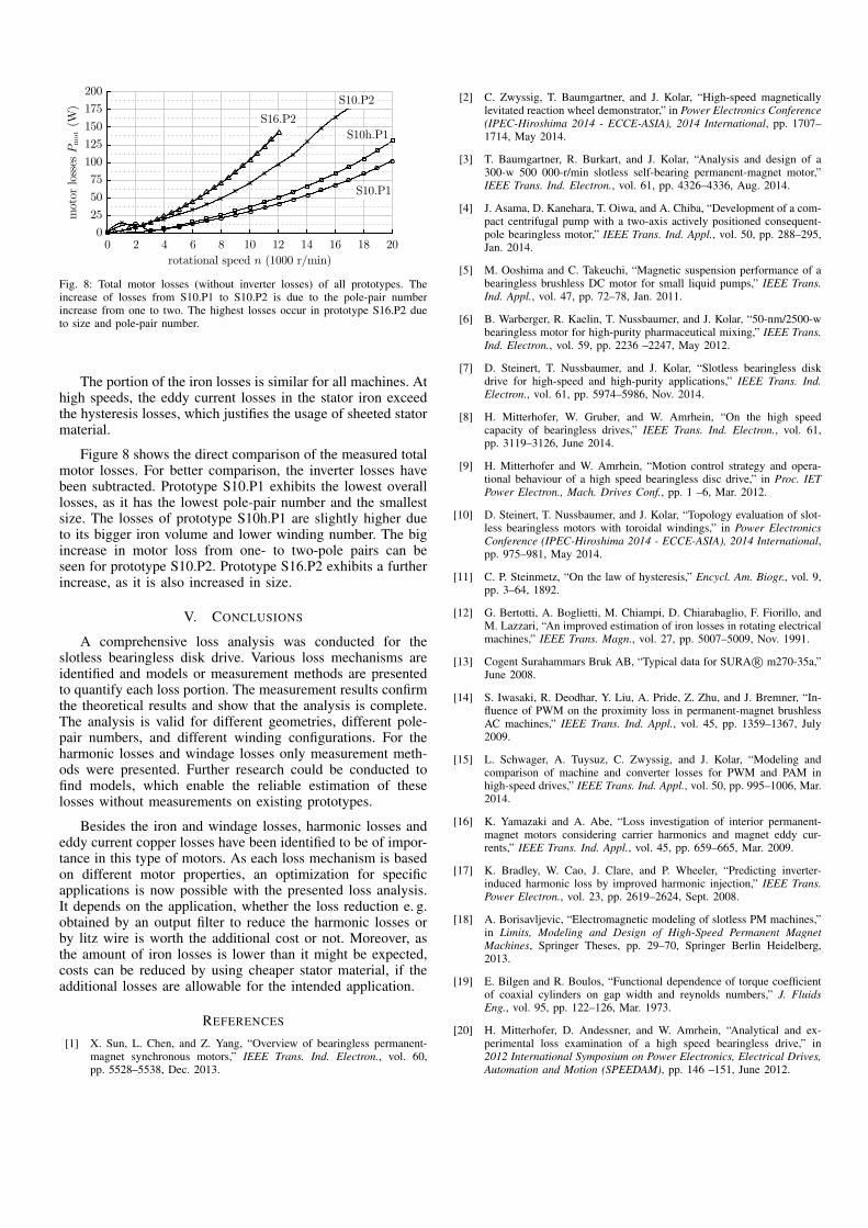
Fig. 8: Total motor losses (without inverter losses) of all prototypes. Theincrease of losses from S10.P1 to S10.P2 is due to the pole-pair numberincrease from one to two. The highest losses occur in prototype S16.P2 dueto size and pole-pair number.
The portion of the iron losses is similar for all machines. Athigh speeds, the eddy current losses in the stator iron exceedthe hysteresis losses, which justifies the usage of sheeted statormaterial.
Figure 8 shows the direct comparison of the measured totalmotor losses. For better comparison, the inverter losses havebeen subtracted. Prototype S10.P1 exhibits the lowest overalllosses, as it has the lowest pole-pair number and the smallestsize. The losses of prototype S10h.P1 are slightly higher dueto its bigger iron volume and lower winding number. The bigincrease in motor loss from one- to two-pole pairs can beseen for prototype S10.P2. Prototype S16.P2 exhibits a furtherincrease, as it is also increased in size.
V. CONCLUSIONS
A comprehensive loss analysis was conducted for theslotless bearingless disk drive. Various loss mechanisms areidentified and models or measurement methods are presentedto quantify each loss portion. The measurement results confirmthe theoretical results and show that the analysis is complete.The analysis is valid for different geometries, different pole-pair numbers, and different winding configurations. For theharmonic losses and windage losses only measurement meth-ods were presented. Further research could be conducted tofind models, which enable the reliable estimation of theselosses without measurements on existing prototypes.
Besides the iron and windage losses, harmonic losses andeddy current copper losses have been identified to be of impor-tance in this type of motors. As each loss mechanism is basedon different motor properties, an optimization for specificapplications is now possible with the presented loss analysis.It depends on the application, whether the loss reduction e. g.obtained by an output filter to reduce the harmonic losses orby litz wire is worth the additional cost or not. Moreover, asthe amount of iron losses is lower than it might be expected,costs can be reduced by using cheaper stator material, if theadditional losses are allowable for the intended application.
REFERENCES
[1] X. Sun, L. Chen, and Z. Yang, “Overview of bearingless permanent-magnet synchronous motors,” IEEE Trans. Ind. Electron., vol. 60,pp. 5528–5538, Dec. 2013.
[2] C. Zwyssig, T. Baumgartner, and J. Kolar, “High-speed magneticallylevitated reaction wheel demonstrator,” in Power Electronics Conference(IPEC-Hiroshima 2014 - ECCE-ASIA), 2014 International, pp. 1707–1714, May 2014.
[3] T. Baumgartner, R. Burkart, and J. Kolar, “Analysis and design of a300-w 500 000-r/min slotless self-bearing permanent-magnet motor,”IEEE Trans. Ind. Electron., vol. 61, pp. 4326–4336, Aug. 2014.
[4] J. Asama, D. Kanehara, T. Oiwa, and A. Chiba, “Development of a com-pact centrifugal pump with a two-axis actively positioned consequent-pole bearingless motor,” IEEE Trans. Ind. Appl., vol. 50, pp. 288–295,Jan. 2014.
[5] M. Ooshima and C. Takeuchi, “Magnetic suspension performance of abearingless brushless DC motor for small liquid pumps,” IEEE Trans.Ind. Appl., vol. 47, pp. 72–78, Jan. 2011.
[6] B. Warberger, R. Kaelin, T. Nussbaumer, and J. Kolar, “50-nm/2500-wbearingless motor for high-purity pharmaceutical mixing,” IEEE Trans.Ind. Electron., vol. 59, pp. 2236 –2247, May 2012.
[7] D. Steinert, T. Nussbaumer, and J. Kolar, “Slotless bearingless diskdrive for high-speed and high-purity applications,” IEEE Trans. Ind.Electron., vol. 61, pp. 5974–5986, Nov. 2014.
[8] H. Mitterhofer, W. Gruber, and W. Amrhein, “On the high speedcapacity of bearingless drives,” IEEE Trans. Ind. Electron., vol. 61,pp. 3119–3126, June 2014.
[9] H. Mitterhofer and W. Amrhein, “Motion control strategy and opera-tional behaviour of a high speed bearingless disc drive,” in Proc. IETPower Electron., Mach. Drives Conf., pp. 1 –6, Mar. 2012.
[10] D. Steinert, T. Nussbaumer, and J. Kolar, “Topology evaluation of slot-less bearingless motors with toroidal windings,” in Power ElectronicsConference (IPEC-Hiroshima 2014 - ECCE-ASIA), 2014 International,pp. 975–981, May 2014.
[11] C. P. Steinmetz, “On the law of hysteresis,” Encycl. Am. Biogr., vol. 9,pp. 3–64, 1892.
[12] G. Bertotti, A. Boglietti, M. Chiampi, D. Chiarabaglio, F. Fiorillo, andM. Lazzari, “An improved estimation of iron losses in rotating electricalmachines,” IEEE Trans. Magn., vol. 27, pp. 5007–5009, Nov. 1991.
[13] Cogent Surahammars Bruk AB, “Typical data for SURA R© m270-35a,”June 2008.
[14] S. Iwasaki, R. Deodhar, Y. Liu, A. Pride, Z. Zhu, and J. Bremner, “In-fluence of PWM on the proximity loss in permanent-magnet brushlessAC machines,” IEEE Trans. Ind. Appl., vol. 45, pp. 1359–1367, July2009.
[15] L. Schwager, A. Tuysuz, C. Zwyssig, and J. Kolar, “Modeling andcomparison of machine and converter losses for PWM and PAM inhigh-speed drives,” IEEE Trans. Ind. Appl., vol. 50, pp. 995–1006, Mar.2014.
[16] K. Yamazaki and A. Abe, “Loss investigation of interior permanent-magnet motors considering carrier harmonics and magnet eddy cur-rents,” IEEE Trans. Ind. Appl., vol. 45, pp. 659–665, Mar. 2009.
[17] K. Bradley, W. Cao, J. Clare, and P. Wheeler, “Predicting inverter-induced harmonic loss by improved harmonic injection,” IEEE Trans.Power Electron., vol. 23, pp. 2619–2624, Sept. 2008.
[18] A. Borisavljevic, “Electromagnetic modeling of slotless PM machines,”in Limits, Modeling and Design of High-Speed Permanent MagnetMachines, Springer Theses, pp. 29–70, Springer Berlin Heidelberg,2013.
[19] E. Bilgen and R. Boulos, “Functional dependence of torque coefficientof coaxial cylinders on gap width and reynolds numbers,” J. FluidsEng., vol. 95, pp. 122–126, Mar. 1973.
[20] H. Mitterhofer, D. Andessner, and W. Amrhein, “Analytical and ex-perimental loss examination of a high speed bearingless drive,” in2012 International Symposium on Power Electronics, Electrical Drives,Automation and Motion (SPEEDAM), pp. 146 –151, June 2012.