Trusty URIs: Verifiable, Immutable, and Permanent Digital Artifacts for Linked Data
687Bull. Pol. Ac.: Tech. 66(5) 2018
BULLETIN OF THE POLISH ACADEMY OF SCIENCES TECHNICAL SCIENCES, Vol. 66, No. 5, 2018DOI: 10.24425/125335
Abstract. This study investigates a digital control system which is used in bearingless permanent magnet synchronous motors (BPMSMs). Com-pared with traditional permanent magnet synchronous motors, a BPMSM is characterized by higher speed and no mechanic friction. Therefore, the application value of the latter to the special area is higher than that of the former. An analysis from previous work on the BPMSM had proved its feasibility, and some performances such as suspension force, inductance and so on were also investigated. Based on this analysis, this study focuses on solving control problems in practical applications by designing a control system. The control system design includes overall schematic, hardware and software designs. Main software systems, including the force/current transform module and closed loop control module for radial displacement, are analyzed. Interface circuit for radial displacement, current feedback circuit and dead zone protection circuit are designed for the hardware system. Finally, several performance experiments have been conducted to verify the effectiveness of the designed digital control system. Experiment results indicate that the rotor has unique characteristics, such as stable suspension performance, good start-of-suspension performance, and rapid anti-disturbance features.
Key words: BPMSMs, digital control system, double-closed speed regulating system, software design, hardware design.
Digital control system design for bearingless permanent magnet synchronous motors
X. SUN1, 2*, Z. SHI1, Z. YANG3, S. WANG1, 2, B. SU1, L. CHEN2, AND K. LI3
1School of Automotive and Traffic Engineering, Jiangsu University, Zhenjiang, 212013, China2Automotive Engineering Research Institute, Jiangsu University, Zhenjiang, 212013, China
3School of Electrical and Information Engineering, Jiangsu University, Zhenjiang, 212013, China
detailed reports in the literature about the design and imple-mentation methods of the digital control system of the BPMSM [21–24]. Focusing on the control system of the BPMSM, the decoupling control between torque and radial suspension force is the key technology for stable suspension control of the BPMSM, therefore the control strategy of rotor flux orien-tation is adopted to conduct decoupling control. Furthermore, an exact model of suspension force also forms an important part for accurate suspension control of BPMSM. In [25], the suspension force mathematic model of BPMSM is presented by taking into account rotor eccentricity with the Maxwell stress tensor modeling scheme. The mathematical model proves not only simple but the result of the experiment shows that it is also effective.
In order to realize the control arithmetic mentioned above, a special integrated complementary metal-oxide semiconductor (CMOS) chip is widely used for motor control [26, 27]. The TMS320F2812, a kind of a digital signal processor (DSP) CMOS chip, which has many merits such as higher integra-tion, higher ability of data processing, higher computing pre-cision, abundant exterior ports, higher real-time performance and also lower price, is widely adopted to fulfil the control strategy [28, 29]. Moreover, it has two event manager modules which can conduct independent control of rotation and sus-pension simultaneously. It provides convenience for achieving the decoupling digital control of a BPMSM with higher per-formance. Additionally, in order to increase reliability of the control system, some protection circuits, such as an overcurrent protection circuit and a dead zone protection circuit, are neces-sary in hardware circuit design.
1. Introduction
Permanent magnet synchronous motors (PMSMs) have gained widespread popularity since they have remarkable advantages such as high efficiency, high power density and high reliability [1–4]. However, for some special circumstances, such as high speed or no-lubrication, PMSMs might not meet the require-ments because of the mechanic friction and wear of mechanical bearings. In order to solve the above problems of mechanical bearings, magnetic bearings in PMSMs become a good solution, but they have a complex structure and entail higher costs [5]. When compared with magnetic bearings, the bearingless per-manent magnet synchronous motors (BPMSMs) have a series of advantages, such as shorter rotor shaft, higher critical speed, simpler structure and lower cost. Thus they have been attracting more and more attention [6, 7].
Although a BPMSM has a relatively simple construction, it requires a complicated control system. Recently, there are pressing requirements for coming up with control technology of a bearingless motor in some high-speed drive scopes, such as the high-speed drive of machine tool spindles, sealed trans-mission of material as well as aviation and aerospace realms [8–11]. At present, many research studies are being conducted on the motor control principle, but most of them are limited to general types of motors [12–20]. Meanwhile. there are very few
*e-mail: [email protected]
Manuscript submitted 2017-08-29, revised 2017-10-29 and 2017-11-20, initially accepted for publication 2018-01-10, published in October 2018.

688
X. Sun, Z. Shi, Z. Yang, S. Wang, B. Su, L. Chen, and K. Li
Bull. Pol. Ac.: Tech. 66(5) 2018
In this paper, the suspension principle of BPMSM is intro-duced firstly in Section 2. Then, in Section 3, general descrip-tions of the BPMSM control system, including software design and hardware design, are conducted. A detailed description of key parts of software and hardware design is shown in sec-tion 4. In Section 5, a number of experiments, including a static suspension experiment and a suspension operation experiment, are carried out to test the effectiveness and stableness of the proposed control system. Finally, Section 6 concludes the paper.
2. Suspension principle of the BPMSM
The BPMSM has two sets of windings, including a torque winding and a suspension winding, which fulfil the following formula:
PS = PT ±1ωS = ωT
(1)
where PT is the pole-pair number of the torque winding, ωT is the current frequency of torque winding, PS is the pole-pair number of the torque winding, and ωS is the current frequency of suspension winding.
The magnetic force in the BPMSM includes Lorentz force and Maxwell force, as per the electromagnetic field theory, and the suspension force is provided by the resultant force emerging from Lorentz force and Maxwell force [30, 31]. In this paper, the prototype has 2 pole-pairs of torque windings and 1 pole pair of suspension windings. As Fig. 1 shows, a single phase suspension winding and a torque winding are used to describe the suspension principle. When the rotor is in the central loca-
tion, the symmetric four-pole magnetic field Ψ4 is generated by A phase torque windings and PMs. If the X phase suspension winding is not excited, there is no suspension force generated because Ψ4 is balanced. When the X phase suspension winding is excited, the two-pole magnetic field Ψ2 is generated, which together with Ψ4 strengthens the magnetic field along the x-axis negative directions. Therefore, the air gap flux density on the right is larger than on the left, which will generate a suspen-sion force Fx along the x-axis positive direction. In contrast, the suspension force Fx along the x-axis negative direction will be generated if a reverse current is provided. Similarly, the suspen-sion force along the y-axis Fy will be generated once the next phase suspension winding is excited.
3. General description of the BPMSM control system
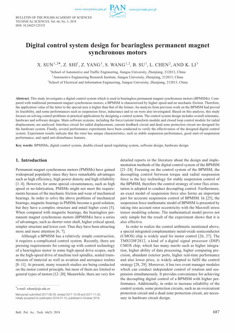
The general scheme description of the BPMSM control system is presented by a hardware block diagram and software algo-rithms block diagram, which are shown in Fig. 2 and 3, re-spectively.
According to Fig. 2, it can be seen that the whole control system can be divided into two parts, with one part being the torque current and speed double-closed loop control system, and the other part being the suspension force control system, which is composed of a radial displacement closed loop system and suspension current closed loop system.
The control system of torque windings is composed of the torque current and speed closed loop system. As shown in the top half of Fig. 2, speed feedback signals n can be obtained from the photoelectric encoder, and the reference signals of speed n* are compared with the corresponding feedback signals while the q-axis current i*
Mq can be derived by sending speed deviation signals to a proportional-integral (PI) controller. Next, the reference signals of d–q axis current i*
Mq and i*Md (i*
Md = 0 is used in this control system) are compared with the d-q axis current feedback signals iMd and iMq, and the signals of α–β axis voltage V*
Mα and V*Mβ can be obtained by sending current
deviation to the PI controller and PARK inverse transformation module. Finally, by using a space-vector pulse width modu-lation (SVPWM) module, the signals of voltage V*
Mα and V*Mβ
can be transformed into six road PWM signals for driving the voltage source inverter, thus constructing a speed closed loop system. The three-phase torque currents are measured by the Hall current sensor, and then they can be transformed into d-q axis current signals i*
Mq and i*Md after PARK transform and
CLARK transform. Therefore, the reference signals of the d–q axis current and feedback d–q axis current signals construct the current closed loop system.
As for the control system of suspension windings, it con-sists in combining radial displacement with a suspension current closed loop system. The shaft’s motion in the bearingless motor subject to research is 2-DOF in radial direction (x and y direc-tion). In axial direction (z direction), the shaft remains fixed. Therefore, the motion of the shaft in the z direction is not con-sidering in this work. As shown in the bottom half of Fig. 2, the Fig. 1. Schematic diagram of the BPMSM
689
Digital control system design for bearingless permanent magnet synchronous motors
Bull. Pol. Ac.: Tech. 66(5) 2018
reference signals of radial displacement x and y are compared with the corresponding signals x* and y*, measured by radial position sensors when the rotor is displaced from the equilib-rium position by an external disturbance. Using a proportional integral derivative (PID) controller, the reference signals of the magnetic suspension force F* x and F* y are derived. Next, sig-nals of the suspension control current i* sd and i* sq are derived by means of the force/current transform module. The rest of the control scheme is the same as the control system for torque windings, which is mentioned above and not explained here.
4. Control system design for the BPMSM
4.1. Hardware design of the digital control system. In this paper, TMS320F2812 series DSP chips are adopted as a core of the control system. The chip is a special DSP device with a 32-bit kernel for motor control. It integrates the quadrate encode pulses (QEP) module, the capture circuit (CAP), the PWM signal generator and the peripheral equipment which is suitable for motor control as well as the analog digital conver-sion (ADC) module and the CPU core with low cost and high
processing ability. Moreover, it has two event managers which can conduct independent control of two inverters simultane-ously and meet the requirements of two sets of windings’ con-trol in the BPMSM. They likewise provide a single chip digital control scheme for the BPMSM control system. Therefore, the TMS320F2812 is an ideal digital control chip to conduct control of the BPMSM.
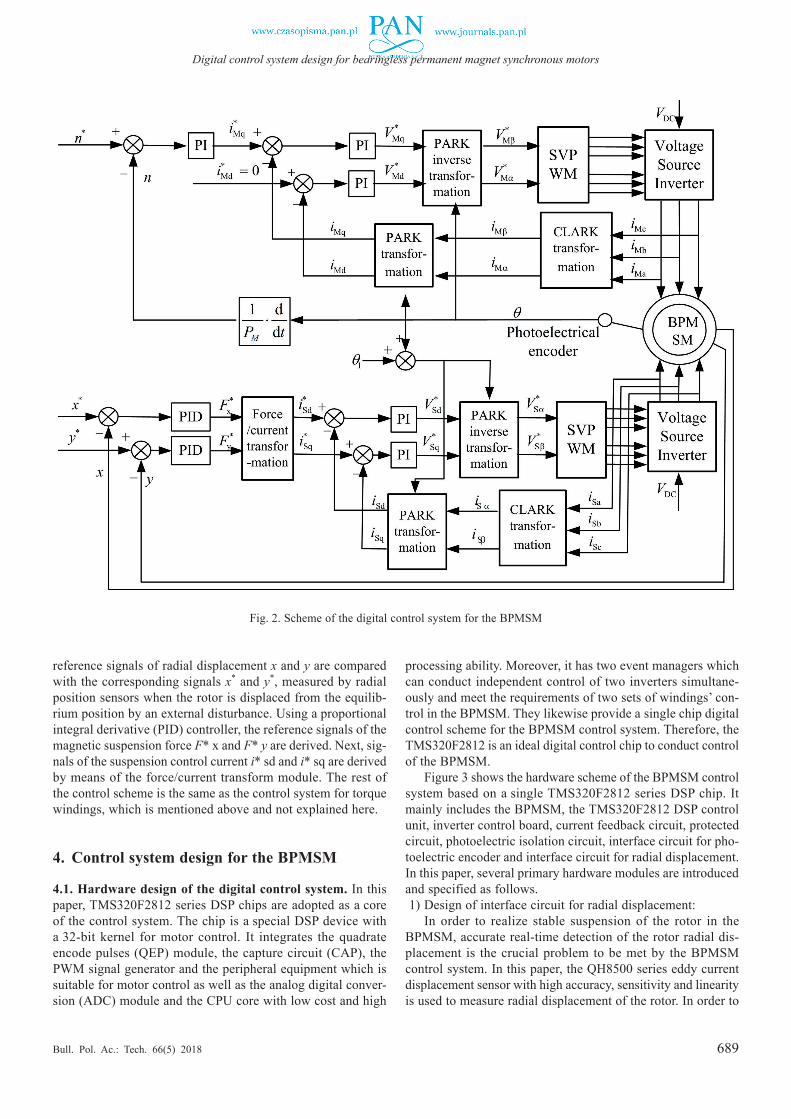
Figure 3 shows the hardware scheme of the BPMSM control system based on a single TMS320F2812 series DSP chip. It mainly includes the BPMSM, the TMS320F2812 DSP control unit, inverter control board, current feedback circuit, protected circuit, photoelectric isolation circuit, interface circuit for pho-toelectric encoder and interface circuit for radial displacement. In this paper, several primary hardware modules are introduced and specified as follows.1) Design of interface circuit for radial displacement:
In order to realize stable suspension of the rotor in the BPMSM, accurate real-time detection of the rotor radial dis-placement is the crucial problem to be met by the BPMSM control system. In this paper, the QH8500 series eddy current displacement sensor with high accuracy, sensitivity and linearity is used to measure radial displacement of the rotor. In order to
Fig. 2. Scheme of the digital control system for the BPMSM
690
X. Sun, Z. Shi, Z. Yang, S. Wang, B. Su, L. Chen, and K. Li
Bull. Pol. Ac.: Tech. 66(5) 2018
improve the accuracy of radial displacement detection, four eddy current displacement sensors are used. Because the input voltage range of the ADC module is 0 » 3 V, and the output voltage of the eddy current sensor is –2 » –18 V, the radial displacement signal detected by the sensor must be processed by the interface circuit for radial displacement before inputting it to ADC module in the DSP.
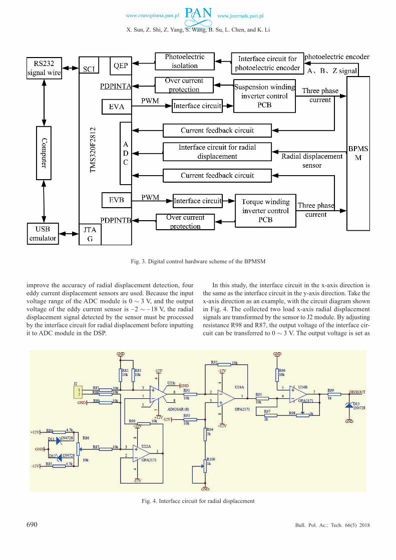
In this study, the interface circuit in the x-axis direction is the same as the interface circuit in the y-axis direction. Take the x-axis direction as an example, with the circuit diagram shown in Fig. 4. The collected two load x-axis radial displacement signals are transformed by the sensor to J2 module. By adjusting resistance R98 and R87, the output voltage of the interface cir-cuit can be transferred to 0 » 3 V. The output voltage is set as
Fig. 3. Digital control hardware scheme of the BPMSM
Fig. 4. Interface circuit for radial displacement
691
Digital control system design for bearingless permanent magnet synchronous motors
Bull. Pol. Ac.: Tech. 66(5) 2018
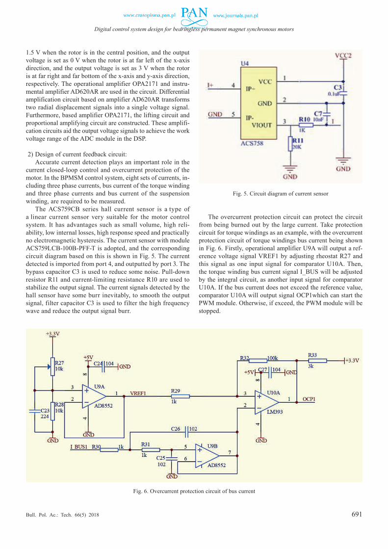
1.5 V when the rotor is in the central position, and the output voltage is set as 0 V when the rotor is at far left of the x-axis direction, and the output voltage is set as 3 V when the rotor is at far right and far bottom of the x-axis and y-axis direction, respectively. The operational amplifier OPA2171 and instru-mental amplifier AD620AR are used in the circuit. Differential amplification circuit based on amplifier AD620AR transforms two radial displacement signals into a single voltage signal. Furthermore, based amplifier OPA2171, the lifting circuit and proportional amplifying circuit are constructed. These amplifi-cation circuits aid the output voltage signals to achieve the work voltage range of the ADC module in the DSP.
2) Design of current feedback circuit:Accurate current detection plays an important role in the
current closed-loop control and overcurrent protection of the motor. In the BPMSM control system, eight sets of currents, in-cluding three phase currents, bus current of the torque winding and three phase currents and bus current of the suspension winding, are required to be measured.
The ACS759CB series hall current sensor is a type of a linear current sensor very suitable for the motor control system. It has advantages such as small volume, high reli-ability, low internal losses, high response speed and practically no electromagnetic hysteresis. The current sensor with module ACS759LCB-100B-PFF-T is adopted, and the corresponding circuit diagram based on this is shown in Fig. 5. The current detected is imported from port 4, and outputted by port 3. The bypass capacitor C3 is used to reduce some noise. Pull-down resistor R11 and current-limiting resistance R10 are used to stabilize the output signal. The current signals detected by the hall sensor have some burr inevitably, to smooth the output signal, filter capacitor C3 is used to filter the high frequency wave and reduce the output signal burr.
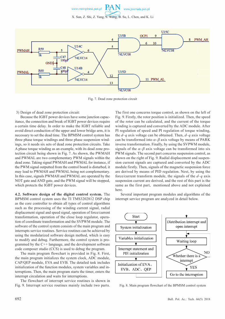
The overcurrent protection circuit can protect the circuit from being burned out by the large current. Take protection circuit for torque windings as an example, with the overcurrent protection circuit of torque windings bus current being shown in Fig. 6. Firstly, operational amplifier U9A will output a ref-erence voltage signal VREF1 by adjusting rheostat R27 and this signal as one input signal for comparator U10A. Then, the torque winding bus current signal I_BUS will be adjusted by the integral circuit, as another input signal for comparator U10A. If the bus current does not exceed the reference value, comparator U10A will output signal OCP1which can start the PWM module. Otherwise, if exceed, the PWM module will be stopped.
Fig. 5. Circuit diagram of current sensor
Fig. 6. Overcurrent protection circuit of bus current
692
X. Sun, Z. Shi, Z. Yang, S. Wang, B. Su, L. Chen, and K. Li
Bull. Pol. Ac.: Tech. 66(5) 2018
3) Design of dead zone protection circuit: Because the IGBT power devices have some junction capac-
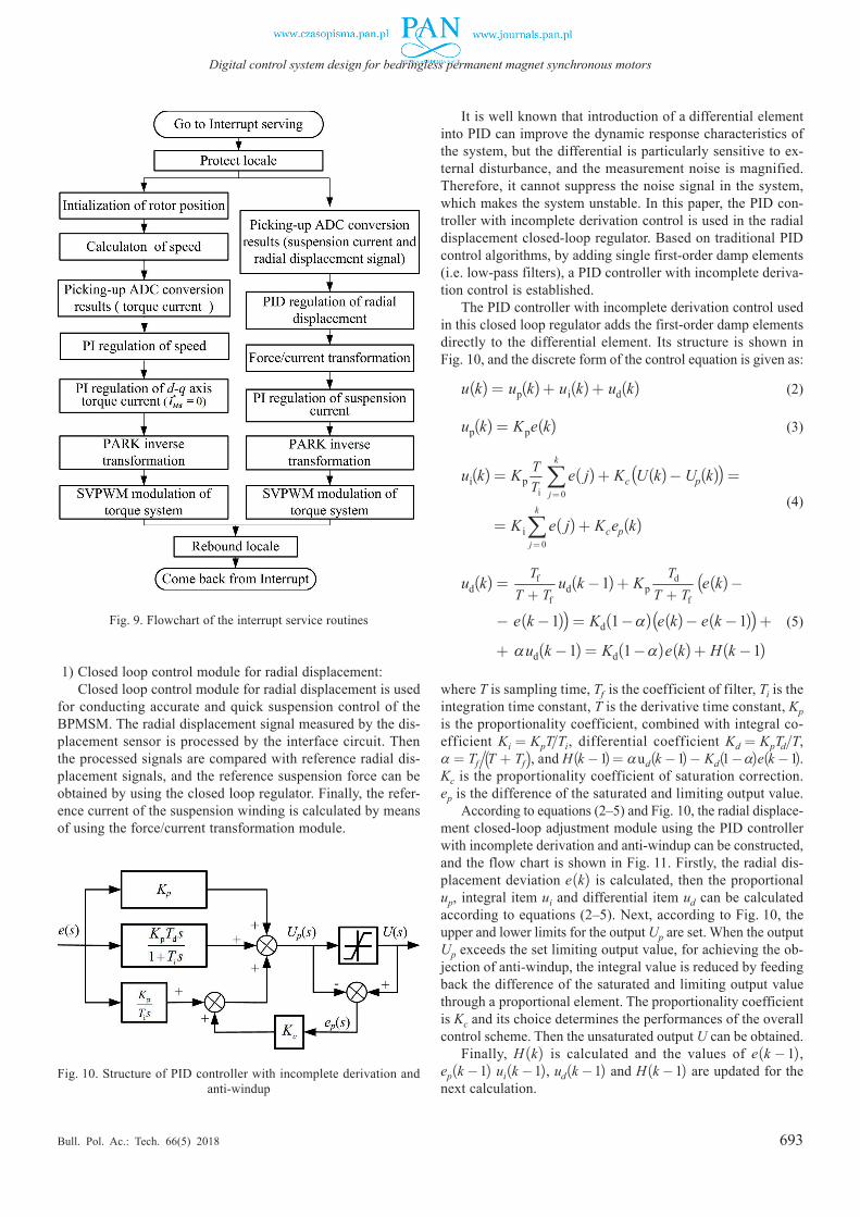
itance, the connection and break of IGBT power devices require a certain time delay. In order to make the IGBT reliable and avoid direct conduction of the upper and lower bridge arm, it is necessary to set the dead time. The BPMSM control system has three phase torque windings and three phase suspension wind-ings, so it needs six sets of dead zone protection circuits. Take A phase torque winding as an example, with its dead zone pro-tection circuit being shown in Fig. 7. As shown, the PWMAH and PWMAL are two complementary PWM signals within the dead zone. Taking signal PWMAH and PWMAL for instance, if the PWM signal outputted from the control board is disturbed, it may lead to PWMAH and PWMAL being not complementary. In this case, signals PWMAH and PWMAL are operated by the NOT gate and AND gate, and the PWM signal will be stopped, which protects the IGBT power devices.
4.2. Software design of the digital control system. The BPMSM control system uses the TI TMS3202812 DSP chip as the core controller to obtain all types of control algorithms such as the processing of the winding current signal, radial displacement signal and speed signal, operation of force/current transformation, operation of the close loop regulator, opera-tion of coordinate transformation and the SVPWM module. The software of the control system consists of the main program and interrupts service routines. Service routines can be achieved by using the modularized software design method, which is easy to modify and debug. Furthermore, the control system is pro-grammed by the C++ language, and the development software code composer studio (CCS) is used to debug the program.
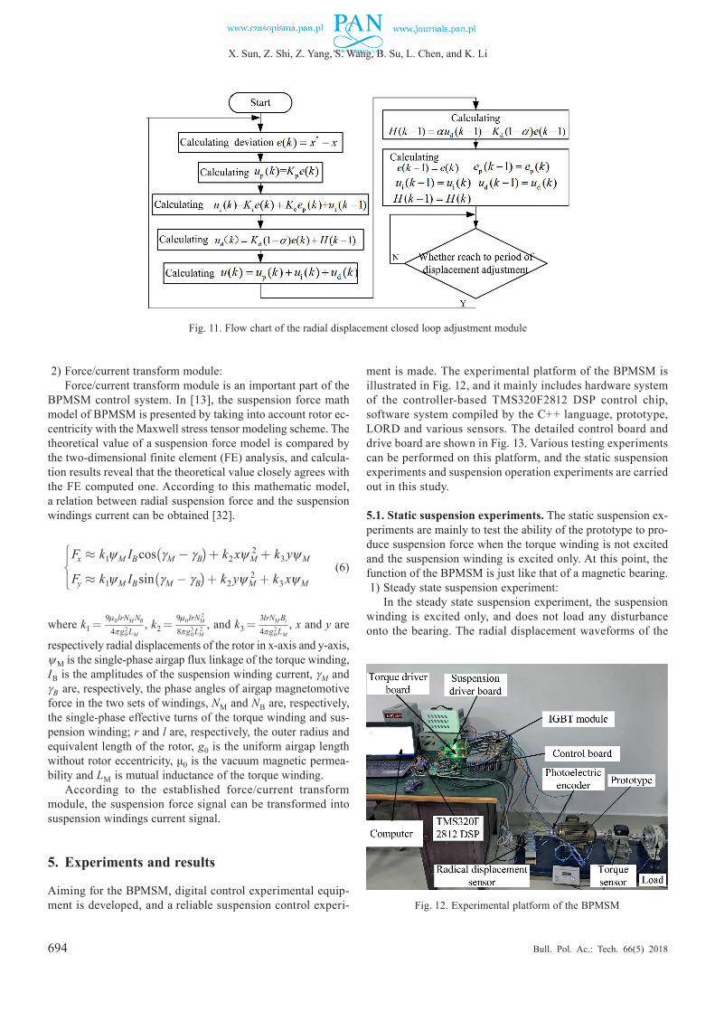
The main program flowchart is provided in Fig. 8. First, the main program initializes the system clock, ADC module, CAP/QEP module, EVA and EVB. The detailed task includes initialization of the function modules, system variables and in-terruptions. Then, the main program starts the timer, enters the interrupt circulation and waits for interruptions.
The flowchart of interrupt service routines is shown in Fig. 9. Interrupt service routines mainly include two parts.
The first one concerns torque control, as shown on the left of Fig. 9. Firstly, the rotor position is initialized. Then, the speed of the rotor can be calculated, and the current of the torque winding is captured and converted by the ADC module. After PI regulation of speed and PI regulation of torque winding, the d–q axis voltage can be obtained. Then, d–q axis voltage can be transformed into α–β axis voltage by means of PARK inverse transformation. Finally, by using the SVPWM module, signals of the α–β axis voltage can be transformed into six PWM signals. The second part concerns suspension control, as shown on the right of Fig. 9. Radial displacement and suspen-sion current signals are captured and converted by the ADC module firstly. Then, signals of the magnetic suspension force are derived by means of PID regulation. Next, by using the force/current transform module, the signals of the d–q axis suspension current are derived, and the rest of this part is the same as the first part, mentioned above and not explained here.
Several important program modules and algorithms of the interrupt service program are analyzed in detail below.
Fig. 7. Dead zone protection circuit
Fig. 8. Main program flowchart of the BPMSM control system
693
Digital control system design for bearingless permanent magnet synchronous motors
Bull. Pol. Ac.: Tech. 66(5) 2018
1) Closed loop control module for radial displacement:Closed loop control module for radial displacement is used
for conducting accurate and quick suspension control of the BPMSM. The radial displacement signal measured by the dis-placement sensor is processed by the interface circuit. Then the processed signals are compared with reference radial dis-placement signals, and the reference suspension force can be obtained by using the closed loop regulator. Finally, the refer-ence current of the suspension winding is calculated by means of using the force/current transformation module.
It is well known that introduction of a differential element into PID can improve the dynamic response characteristics of the system, but the differential is particularly sensitive to ex-ternal disturbance, and the measurement noise is magnified. Therefore, it cannot suppress the noise signal in the system, which makes the system unstable. In this paper, the PID con-troller with incomplete derivation control is used in the radial displacement closed-loop regulator. Based on traditional PID control algorithms, by adding single first-order damp elements (i.e. low-pass filters), a PID controller with incomplete deriva-tion control is established.
The PID controller with incomplete derivation control used in this closed loop regulator adds the first-order damp elements directly to the differential element. Its structure is shown in Fig. 10, and the discrete form of the control equation is given as:
u(k) = up(k) + ui(k) + ud(k) (2)
up(k) = Kpe(k) (3)
ui(k) = KpTTi
k
j=0∑ e( j) + Kc(U(k) ¡ Up(k)) =
ui(k) = K i
k
j=0∑ e( j) + Kcep(k)
(4)
ud(k) = Tf
T + Tfud(k ¡ 1) + Kp
Td
T + Tf(e(k) ¡
ud(k) ¡ e(k ¡ 1)) = Kd(1 ¡ α)(e(k) ¡ e(k ¡ 1)) +
ud(k) + αud(k ¡ 1) = Kd(1 ¡ α)e(k) + H(k ¡ 1)
(5)
where T is sampling time, Tf is the coefficient of filter, Ti is the integration time constant, T is the derivative time constant, Kp is the proportionality coefficient, combined with integral co-efficient Ki = KpT/Ti, differential coefficient Kd = KpTd/T, α = Tf/ (T + Tf), and H(k ¡ 1) = αud(k ¡ 1) ¡ Kd(1 ¡ α)e(k ¡ 1). Kc is the proportionality coefficient of saturation correction. ep is the difference of the saturated and limiting output value.
According to equations (2‒5) and Fig. 10, the radial displace-ment closed-loop adjustment module using the PID controller with incomplete derivation and anti-windup can be constructed, and the flow chart is shown in Fig. 11. Firstly, the radial dis-placement deviation e(k) is calculated, then the proportional up, integral item ui and differential item ud can be calculated according to equations (2‒5). Next, according to Fig. 10, the upper and lower limits for the output Up are set. When the output Up exceeds the set limiting output value, for achieving the ob-jection of anti-windup, the integral value is reduced by feeding back the difference of the saturated and limiting output value through a proportional element. The proportionality coefficient is Kc and its choice determines the performances of the overall control scheme. Then the unsaturated output U can be obtained.
Finally, H(k) is calculated and the values of e(k ¡ 1), ep(k ¡ 1) ui(k ¡ 1), ud(k ¡ 1) and H(k ¡ 1) are updated for the next calculation.
Fig. 9. Flowchart of the interrupt service routines
Fig. 10. Structure of PID controller with incomplete derivation and anti-windup
694
X. Sun, Z. Shi, Z. Yang, S. Wang, B. Su, L. Chen, and K. Li
Bull. Pol. Ac.: Tech. 66(5) 2018
2) Force/current transform module:Force/current transform module is an important part of the
BPMSM control system. In [13], the suspension force math model of BPMSM is presented by taking into account rotor ec-centricity with the Maxwell stress tensor modeling scheme. The theoretical value of a suspension force model is compared by the two-dimensional finite element (FE) analysis, and calcula-tion results reveal that the theoretical value closely agrees with the FE computed one. According to this mathematic model, a relation between radial suspension force and the suspension windings current can be obtained [32].
Fx ¼ k1ψM IBcos(γM ¡ γB) + k2xψM
2 + k3 yψM
Fy ¼ k1ψM IBsin(γM ¡ γB) + k2 yψM2 + k3 xψM
(6)
where k1 = 9µ0lrNM NB
4πg02 LM
, k2 = 9µ0lrNM2
8πg03LM
2 , and k3 = 3lrNM Bt
4πg02 LM
, x and y are
respectively radial displacements of the rotor in x-axis and y-axis, ψM is the single-phase airgap flux linkage of the torque winding, IB is the amplitudes of the suspension winding current, γM and γB are, respectively, the phase angles of airgap magnetomotive force in the two sets of windings, NM and NB are, respectively, the single-phase effective turns of the torque winding and sus-pension winding; r and l are, respectively, the outer radius and equivalent length of the rotor, g0 is the uniform airgap length without rotor eccentricity, μ0 is the vacuum magnetic permea-bility and LM is mutual inductance of the torque winding.
According to the established force/current transform module, the suspension force signal can be transformed into suspension windings current signal.
5. Experiments and results
Aiming for the BPMSM, digital control experimental equip-ment is developed, and a reliable suspension control experi-
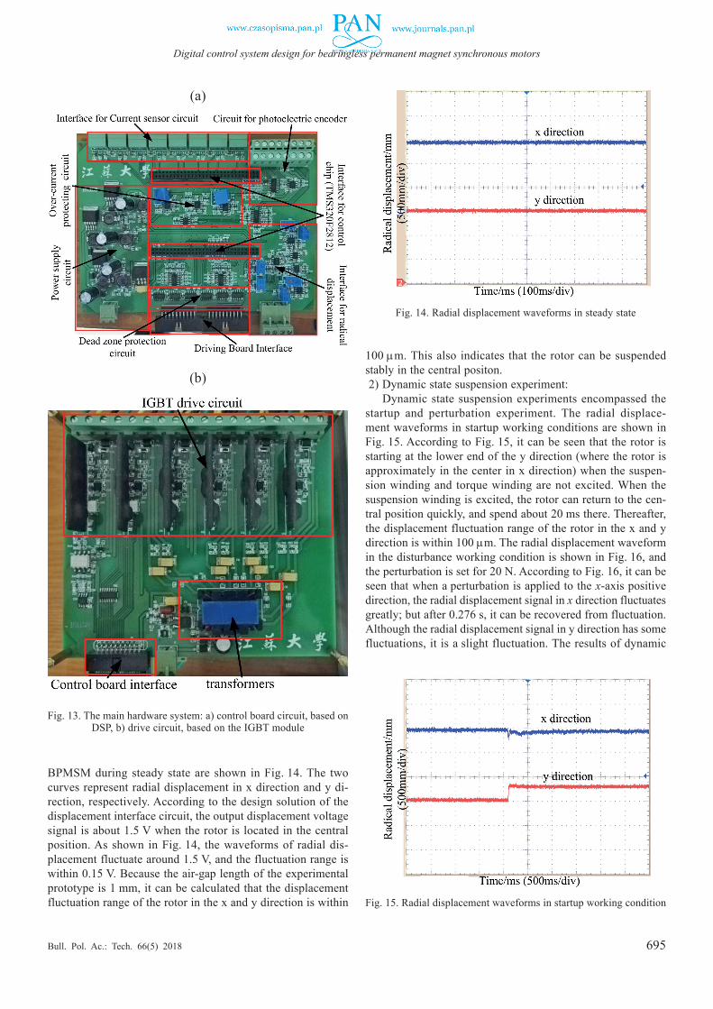
ment is made. The experimental platform of the BPMSM is illustrated in Fig. 12, and it mainly includes hardware system of the controller-based TMS320F2812 DSP control chip, software system compiled by the C++ language, prototype, LORD and various sensors. The detailed control board and drive board are shown in Fig. 13. Various testing experiments can be performed on this platform, and the static suspension experiments and suspension operation experiments are carried out in this study.
5.1. Static suspension experiments. The static suspension ex-periments are mainly to test the ability of the prototype to pro-duce suspension force when the torque winding is not excited and the suspension winding is excited only. At this point, the function of the BPMSM is just like that of a magnetic bearing.1) Steady state suspension experiment:
In the steady state suspension experiment, the suspension winding is excited only, and does not load any disturbance onto the bearing. The radial displacement waveforms of the
Fig. 11. Flow chart of the radial displacement closed loop adjustment module
Fig. 12. Experimental platform of the BPMSM
695
Digital control system design for bearingless permanent magnet synchronous motors
Bull. Pol. Ac.: Tech. 66(5) 2018
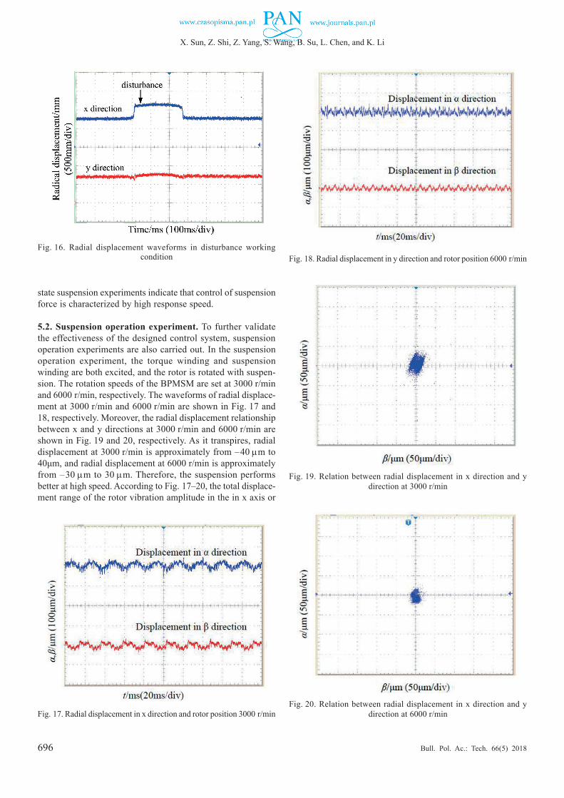
BPMSM during steady state are shown in Fig. 14. The two curves represent radial displacement in x direction and y di-rection, respectively. According to the design solution of the displacement interface circuit, the output displacement voltage signal is about 1.5 V when the rotor is located in the central position. As shown in Fig. 14, the waveforms of radial dis-placement fluctuate around 1.5 V, and the fluctuation range is within 0.15 V. Because the air-gap length of the experimental prototype is 1 mm, it can be calculated that the displacement fluctuation range of the rotor in the x and y direction is within
Fig. 13. The main hardware system: a) control board circuit, based on DSP, b) drive circuit, based on the IGBT module
(a)
(b)
Fig. 14. Radial displacement waveforms in steady state
Fig. 15. Radial displacement waveforms in startup working condition
100 µm. This also indicates that the rotor can be suspended stably in the central positon.2) Dynamic state suspension experiment:
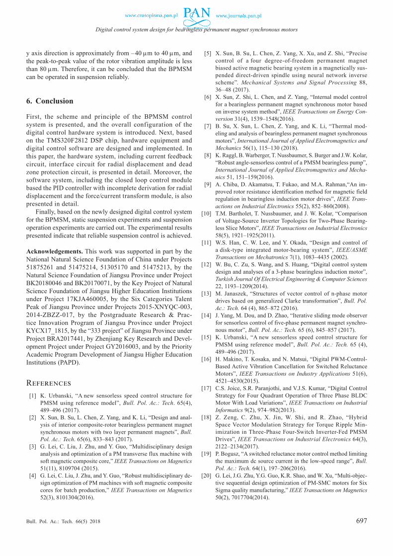
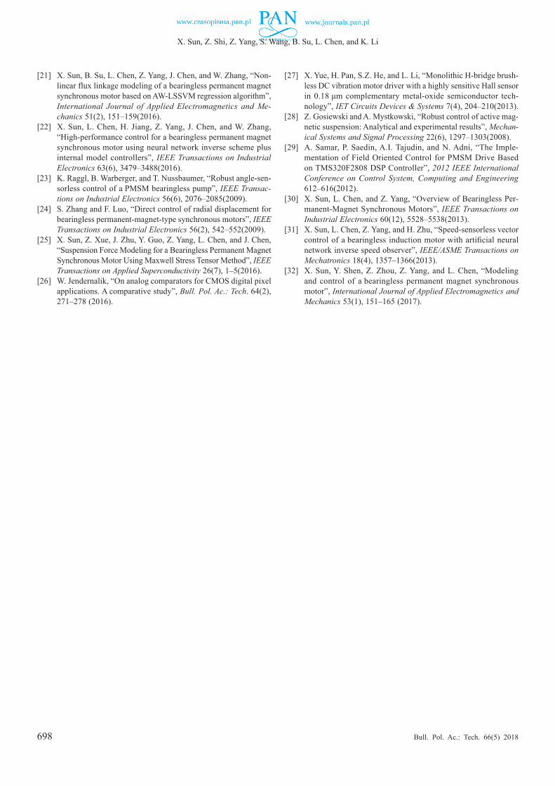
Dynamic state suspension experiments encompassed the startup and perturbation experiment. The radial displace-ment waveforms in startup working conditions are shown in Fig. 15. According to Fig. 15, it can be seen that the rotor is starting at the lower end of the y direction (where the rotor is approximately in the center in x direction) when the suspen-sion winding and torque winding are not excited. When the suspension winding is excited, the rotor can return to the cen-tral position quickly, and spend about 20 ms there. Thereafter, the displacement fluctuation range of the rotor in the x and y direction is within 100 µm. The radial displacement waveform in the disturbance working condition is shown in Fig. 16, and the perturbation is set for 20 N. According to Fig. 16, it can be seen that when a perturbation is applied to the x-axis positive direction, the radial displacement signal in x direction fluctuates greatly; but after 0.276 s, it can be recovered from fluctuation. Although the radial displacement signal in y direction has some fluctuations, it is a slight fluctuation. The results of dynamic
696
X. Sun, Z. Shi, Z. Yang, S. Wang, B. Su, L. Chen, and K. Li
Bull. Pol. Ac.: Tech. 66(5) 2018
Fig. 16. Radial displacement waveforms in disturbance working condition Fig. 18. Radial displacement in y direction and rotor position 6000 r/min
Fig. 19. Relation between radial displacement in x direction and y direction at 3000 r/min
Fig. 20. Relation between radial displacement in x direction and y direction at 6000 r/minFig. 17. Radial displacement in x direction and rotor position 3000 r/min
state suspension experiments indicate that control of suspension force is characterized by high response speed.
5.2. Suspension operation experiment. To further validate the effectiveness of the designed control system, suspension operation experiments are also carried out. In the suspension operation experiment, the torque winding and suspension winding are both excited, and the rotor is rotated with suspen-sion. The rotation speeds of the BPMSM are set at 3000 r/min and 6000 r/min, respectively. The waveforms of radial displace-ment at 3000 r/min and 6000 r/min are shown in Fig. 17 and 18, respectively. Moreover, the radial displacement relationship between x and y directions at 3000 r/min and 6000 r/min are shown in Fig. 19 and 20, respectively. As it transpires, radial displacement at 3000 r/min is approximately from –40 µm to 40μm, and radial displacement at 6000 r/min is approximately from –30 µm to 30 µm. Therefore, the suspension performs better at high speed. According to Fig. 17–20, the total displace-ment range of the rotor vibration amplitude in the in x axis or
697
Digital control system design for bearingless permanent magnet synchronous motors
Bull. Pol. Ac.: Tech. 66(5) 2018
y axis direction is approximately from –40 µm to 40 µm, and the peak-to-peak value of the rotor vibration amplitude is less than 80 µm. Therefore, it can be concluded that the BPMSM can be operated in suspension reliably.
6. Conclusion
First, the scheme and principle of the BPMSM control system is presented, and the overall configuration of the digital control hardware system is introduced. Next, based on the TMS320F2812 DSP chip, hardware equipment and digital control software are designed and implemented. In this paper, the hardware system, including current feedback circuit, interface circuit for radial displacement and dead zone protection circuit, is presented in detail. Moreover, the software system, including the closed loop control module based the PID controller with incomplete derivation for radial displacement and the force/current transform module, is also presented in detail.
Finally, based on the newly designed digital control system for the BPMSM, static suspension experiments and suspension operation experiments are carried out. The experimental results presented indicate that reliable suspension control is achieved.
Acknowledgements. This work was supported in part by the National Natural Science Foundation of China under Projects 51875261 and 51475214, 51305170 and 51475213, by the Natural Science Foundation of Jiangsu Province under Project BK20180046 and BK20170071, by the Key Project of Natural Science Foundation of Jiangsu Higher Education Institutions under Project 17KJA460005, by the Six Categories Talent Peak of Jiangsu Province under Projects 2015-XNYQC-003, 2014-ZBZZ-017, by the Postgraduate Research & Prac-tice Innovation Program of Jiangsu Province under Project KYCX17_1815, by the “333 project” of Jiangsu Province under Project BRA2017441, by Zhenjiang Key Research and Devel-opment Project under Project GY2016003, and by the Priority Academic Program Development of Jiangsu Higher Education Institutions (PAPD).
References [1] K. Urbanski, “A new sensorless speed control structure for
PMSM using reference model”, Bull. Pol. Ac.: Tech. 65(4), 489‒496 (2017).
[2] X. Sun, B. Su, L. Chen, Z. Yang, and K. Li, “Design and anal-ysis of interior composite-rotor bearingless permanent magnet synchronous motors with two layer permanent magnets”, Bull. Pol. Ac.: Tech. 65(6), 833‒843 (2017).
[3] G. Lei, C. Liu, J. Zhu, and Y. Guo, “Multidisciplinary design analysis and optimization of a PM transverse flux machine with soft magnetic composite core,” IEEE Transactions on Magnetics 51(11), 8109704 (2015).
[4] G. Lei, C. Liu, J. Zhu, and Y. Guo, “Robust multidisciplinary de-sign optimization of PM machines with soft magnetic composite cores for batch production,” IEEE Transactions on Magnetics 52(3), 8101304(2016).
[5] X. Sun, B. Su, L. Chen, Z. Yang, X. Xu, and Z. Shi, “Precise control of a four degree-of-freedom permanent magnet biased active magnetic bearing system in a magnetically sus-pended direct-driven spindle using neural network inverse scheme”. Mechanical Systems and Signal Processing 88, 36‒48 (2017).
[6] X. Sun, Z. Shi, L. Chen, and Z. Yang, “Internal model control for a bearingless permanent magnet synchronous motor based on inverse system method”, IEEE Transactions on Energy Con-version 31(4), 1539‒1548(2016).
[7] B. Su, X. Sun, L. Chen, Z. Yang, and K. Li, “Thermal mod-eling and analysis of bearingless permanent magnet synchronous motors”, International Journal of Applied Electromagnetics and Mechanics 56(1), 115‒130 (2018).
[8] K. Raggl, B. Warberger, T. Nussbaumer, S. Burger and J.W. Kolar, “Robust angle-sensorless control of a PMSM bearingless pump”, International Journal of Applied Electromagnetics and Mecha-nics 51, 151‒159(2016).
[9] A. Chiba, D. Akamatsu, T. Fukao, and M.A. Rahman,“An im-proved rotor resistance identification method for magnetic field regulation in bearingless induction motor drives”, IEEE Trans-actions on Industrial Electronics 55(2), 852‒860(2008).
[10] T.M. Bartholet, T. Nussbaumer, and J. W. Kolar, “Comparison of Voltage-Source Inverter Topologies for Two-Phase Bearing-less Slice Motors”, IEEE Transactions on Industrial Electronics 58(5), 1921‒1925(2011).
[11] W.S. Han, C. W. Lee, and Y. Okada, “Design and control of a disk-type integrated motor-bearing system”, IEEE/ASME Transactions on Mechatronics 7(1), 1083‒4435 (2002).
[12] W. Bu, C. Zu, S. Wang, and S. Huang, “Digital control system design and analyses of a 3-phase bearingless induction motor”, Turkish Journal Of Electrical Engineering & Computer Sciences 22, 1193‒1209(2014).
[13] M. Janaszek, “Structures of vector control of n-phase motor drives based on generalized Clarke transformation”, Bull. Pol. Ac.: Tech. 64 (4), 865‒872 (2016).
[14] J. Yang, M. Dou, and D. Zhao, “Iterative sliding mode observer for sensorless control of five-phase permanent magnet synchro-nous motor”, Bull. Pol. Ac.: Tech. 65 (6), 845‒857 (2017).
[15] K. Urbanski, “A new sensorless speed control structure for PMSM using reference model”, Bull. Pol. Ac.: Tech. 65 (4), 489‒496 (2017).
[16] H. Makino, T. Kosaka, and N. Matsui, “Digital PWM-Control-Based Active Vibration Cancellation for Switched Reluctance Motors”, IEEE Transactions on Industry Applications 51(6), 4521‒4530(2015).
[17] C.S. Joice, S.R. Paranjothi, and V.J.S. Kumar, “Digital Control Strategy for Four Quadrant Operation of Three Phase BLDC Motor With Load Variations”, IEEE Transactions on Industrial Informatics 9(2), 974‒982(2013).
[18] Z. Zeng, C. Zhu, X. Jin, W. Shi, and R. Zhao, “Hybrid Space Vector Modulation Strategy for Torque Ripple Min-imization in Three-Phase Four-Switch Inverter-Fed PMSM Drives”, IEEE Transactions on Industrial Electronics 64(3), 2122‒2134(2017).
[19] P. Bogusz, “A switched reluctance motor control method limiting the maximum dc source current in the low-speed range”, Bull. Pol. Ac.: Tech. 64(1), 197‒206(2016).
[20] G. Lei, J.G. Zhu, Y.G. Guo, K.R. Shao, and W. Xu, “Multi-objec-tive sequential design optimization of PM-SMC motors for Six Sigma quality manufacturing,” IEEE Transactions on Magnetics 50(2), 7017704(2014).
698
X. Sun, Z. Shi, Z. Yang, S. Wang, B. Su, L. Chen, and K. Li
Bull. Pol. Ac.: Tech. 66(5) 2018
[21] X. Sun, B. Su, L. Chen, Z. Yang, J. Chen, and W. Zhang, “Non-linear flux linkage modeling of a bearingless permanent magnet synchronous motor based on AW-LSSVM regression algorithm”, International Journal of Applied Electromagnetics and Me-chanics 51(2), 151‒159(2016).
[22] X. Sun, L. Chen, H. Jiang, Z. Yang, J. Chen, and W. Zhang, “High-performance control for a bearingless permanent magnet synchronous motor using neural network inverse scheme plus internal model controllers”, IEEE Transactions on Industrial Electronics 63(6), 3479‒3488(2016).
[23] K. Raggl, B. Warberger, and T. Nussbaumer, “Robust angle-sen-sorless control of a PMSM bearingless pump”, IEEE Transac-tions on Industrial Electronics 56(6), 2076‒2085(2009).
[24] S. Zhang and F. Luo, “Direct control of radial displacement for bearingless permanent-magnet-type synchronous motors”, IEEE Transactions on Industrial Electronics 56(2), 542‒552(2009).
[25] X. Sun, Z. Xue, J. Zhu, Y. Guo, Z. Yang, L. Chen, and J. Chen, “Suspension Force Modeling for a Bearingless Permanent Magnet Synchronous Motor Using Maxwell Stress Tensor Method”, IEEE Transactions on Applied Superconductivity 26(7), 1‒5(2016).
[26] W. Jendernalik, “On analog comparators for CMOS digital pixel applications. A comparative study”, Bull. Pol. Ac.: Tech. 64(2), 271‒278 (2016).
[27] X. Yue, H. Pan, S.Z. He, and L. Li, “Monolithic H-bridge brush-less DC vibration motor driver with a highly sensitive Hall sensor in 0.18 μm complementary metal-oxide semiconductor tech-nology”, IET Circuits Devices & Systems 7(4), 204‒210(2013).
[28] Z. Gosiewski and A. Mystkowski, “Robust control of active mag-netic suspension: Analytical and experimental results”, Mechan-ical Systems and Signal Processing 22(6), 1297‒1303(2008).
[29] A. Samar, P. Saedin, A.I. Tajudin, and N. Adni, “The Imple-mentation of Field Oriented Control for PMSM Drive Based on TMS320F2808 DSP Controller”, 2012 IEEE International Conference on Control System, Computing and Engineering 612‒616(2012).
[30] X. Sun, L. Chen, and Z. Yang, “Overview of Bearingless Per-manent-Magnet Synchronous Motors”, IEEE Transactions on Industrial Electronics 60(12), 5528‒5538(2013).
[31] X. Sun, L. Chen, Z. Yang, and H. Zhu, “Speed-sensorless vector control of a bearingless induction motor with artificial neural network inverse speed observer”, IEEE/ASME Transactions on Mechatronics 18(4), 1357‒1366(2013).
[32] X. Sun, Y. Shen, Z. Zhou, Z. Yang, and L. Chen, “Modeling and control of a bearingless permanent magnet synchronous motor”, International Journal of Applied Electromagnetics and Mechanics 53(1), 151‒165 (2017).