Design and Validation of a Software Defined Radio … · This paper describes the design and...
12
RADIOENGINEERING, VOL. 23, NO. 1, APRIL 2014 387 Design and Validation of a Software Defined Radio Testbed for DVB-T Transmission Giuseppe BARUFFA, Luca RUGINI, Paolo BANELLI Dept. of Engineering, University of Perugia, Via G. Duranti 93, 06125 Perugia, Italy [email protected], [email protected], [email protected] Abstract. This paper describes the design and validation of a Software Defined Radio (SDR) testbed, which can be used for Digital Television transmission using the Digital Video Broadcasting - Terrestrial (DVB-T) standard. In order to generate a DVB-T-compliant signal with low computational complexity, we design an SDR architecture that uses the C/C++ language and exploits multithreading and vectorized instructions. Then, we transmit the gener- ated DVB-T signal in real time, using a common PC equipped with multicore central processing units (CPUs) and a commercially available SDR modem board. The proposed SDR architecture has been validated using fixed TV sets, and portable receivers. Our results show that the proposed SDR architecture for DVB-T transmission is a low-cost low-complexity solution that, in the worst case, only requires less than 22% of CPU load and less than 170 MB of memory usage, on a 3.0 GHz Core i7 processor. In addition, using the same SDR modem board, we design an off-line software receiver that also performs time syn- chronization and carrier frequency offset estimation and compensation. Keywords Software Defined Radio, Digital Video Broadcasting- Terrestrial, USRP, OFDM, time synchronization, carrier frequency offset estimation. 1. Introduction The implementation of digital modulators used in many commercial standards to be used for personal com- munications, such as Global System for Mobile Communi- cations (GSM), Universal Mobile Telecommunications System (UMTS), Long Term Evolution (LTE), or for broadcasting purposes, such as the Advanced Television Systems Committee (ATSC) and the European Digital Video Broadcasting (DVB) [1], [2], has classically adopted customized or reprogrammable device-based architectures, using either application-specific integrated circuits (ASICs), field-programmable gate arrays (FPGAs), or digital signal processors (DSPs). The high cost of such dedicated solutions, mainly due to the relatively small number of systems sold, which are required to cover a wide area of possible users, has always been a limiting factor for a thorough adoption of such technologies in under-popu- lated territories or developing countries. However, due to the implications of Moore's Law, the technological limits of central processing units (CPUs) are being pushed to a level where the computational performance of such de- vices is becoming almost on par with that of DSPs or FPGAs. This means that software defined radio (SDR) is becoming feasible in a number of applications, which were before relegated to being implemented in ASICs or FPGAs/DSPs [3], [4]. In this way, a single transmitter can potentially impersonate multiple communication standards using one or more dedicated software stacks running on top of a nonintrusive operating system (OS) kernel and adopting low-cost and widely-available PCs with multicore CPUs [5][7]. A common software framework used by many projects is represented by GNU Radio [8], an open- source software development toolkit that provides signal processing blocks to implement SDR. The only remaining HW needed is represented by the digital-to-analog con- verter (DAC) and by a radio frequency (RF) quadrature modulator. Recently, a number of projects have shown the feasi- bility of SDR using modern, versatile, low-cost radios and common CPUs. Open Base Transceiver Station (OpenBTS) uses a common PC with SDR hardware to present a GSM air interface to standard 2G GSM handsets and uses a software switch to connect calls [9], [10]. The system allows for a new type of cellular network that can be operated at low cost, such as private networks in rural deployments, remote areas, or developing countries [11], [12]. In the context of cellular communications, Amarisoft LTE 100 is a low-cost LTE base station running on a PC [13], and the Open Source Long-Term Evolution Deploy- ment (OSLD) is a project aimed at designing a complete open source LTE stack [14]. Digital broadcasting stan- dards, also, were explored in the technical literature, as possibly to be developed using SDR. In [15], the authors presented a DVB simulation system jointly using an MDS TM-13 IREF DSP board and a host PC, adopted for real- time demonstration of error protection influence on trans- mitted digital video. Soft-DVB [16] is a GNU Radio-based modulator for Digital Video Broadcasting - Terrestrial (DVB-T) signals [1], with the RF front-end provided by
Transcript of Design and Validation of a Software Defined Radio … · This paper describes the design and...

RADIOENGINEERING, VOL. 23, NO. 1, APRIL 2014 387
Design and Validation of a Software Defined Radio Testbed for DVB-T Transmission
Giuseppe BARUFFA, Luca RUGINI, Paolo BANELLI
Dept. of Engineering, University of Perugia, Via G. Duranti 93, 06125 Perugia, Italy
[email protected], [email protected], [email protected]
Abstract. This paper describes the design and validation of a Software Defined Radio (SDR) testbed, which can be used for Digital Television transmission using the Digital Video Broadcasting - Terrestrial (DVB-T) standard. In order to generate a DVB-T-compliant signal with low computational complexity, we design an SDR architecture that uses the C/C++ language and exploits multithreading and vectorized instructions. Then, we transmit the gener-ated DVB-T signal in real time, using a common PC equipped with multicore central processing units (CPUs) and a commercially available SDR modem board. The proposed SDR architecture has been validated using fixed TV sets, and portable receivers. Our results show that the proposed SDR architecture for DVB-T transmission is a low-cost low-complexity solution that, in the worst case, only requires less than 22% of CPU load and less than 170 MB of memory usage, on a 3.0 GHz Core i7 processor. In addition, using the same SDR modem board, we design an off-line software receiver that also performs time syn-chronization and carrier frequency offset estimation and compensation.
Keywords Software Defined Radio, Digital Video Broadcasting-Terrestrial, USRP, OFDM, time synchronization, carrier frequency offset estimation.
1. Introduction The implementation of digital modulators used in
many commercial standards to be used for personal com-munications, such as Global System for Mobile Communi-cations (GSM), Universal Mobile Telecommunications System (UMTS), Long Term Evolution (LTE), or for broadcasting purposes, such as the Advanced Television Systems Committee (ATSC) and the European Digital Video Broadcasting (DVB) [1], [2], has classically adopted customized or reprogrammable device-based architectures, using either application-specific integrated circuits (ASICs), field-programmable gate arrays (FPGAs), or digital signal processors (DSPs). The high cost of such dedicated solutions, mainly due to the relatively small
number of systems sold, which are required to cover a wide area of possible users, has always been a limiting factor for a thorough adoption of such technologies in under-popu-lated territories or developing countries. However, due to the implications of Moore's Law, the technological limits of central processing units (CPUs) are being pushed to a level where the computational performance of such de-vices is becoming almost on par with that of DSPs or FPGAs. This means that software defined radio (SDR) is becoming feasible in a number of applications, which were before relegated to being implemented in ASICs or FPGAs/DSPs [3], [4]. In this way, a single transmitter can potentially impersonate multiple communication standards using one or more dedicated software stacks running on top of a nonintrusive operating system (OS) kernel and adopting low-cost and widely-available PCs with multicore CPUs [5][7]. A common software framework used by many projects is represented by GNU Radio [8], an open-source software development toolkit that provides signal processing blocks to implement SDR. The only remaining HW needed is represented by the digital-to-analog con-verter (DAC) and by a radio frequency (RF) quadrature modulator.
Recently, a number of projects have shown the feasi-bility of SDR using modern, versatile, low-cost radios and common CPUs. Open Base Transceiver Station (OpenBTS) uses a common PC with SDR hardware to present a GSM air interface to standard 2G GSM handsets and uses a software switch to connect calls [9], [10]. The system allows for a new type of cellular network that can be operated at low cost, such as private networks in rural deployments, remote areas, or developing countries [11], [12]. In the context of cellular communications, Amarisoft LTE 100 is a low-cost LTE base station running on a PC [13], and the Open Source Long-Term Evolution Deploy-ment (OSLD) is a project aimed at designing a complete open source LTE stack [14]. Digital broadcasting stan-dards, also, were explored in the technical literature, as possibly to be developed using SDR. In [15], the authors presented a DVB simulation system jointly using an MDS TM-13 IREF DSP board and a host PC, adopted for real-time demonstration of error protection influence on trans-mitted digital video. Soft-DVB [16] is a GNU Radio-based modulator for Digital Video Broadcasting - Terrestrial (DVB-T) signals [1], with the RF front-end provided by

388 G. BARUFFA, L. RUGINI, P. BANELLI, DESIGN AND VALIDATION OF A SDR TESTBED FOR DVB-T TRANSMISSION
the universal software radio peripheral (USRP) [17], and a CPU software section integrating C++ code into the GNU Radio hybrid C++/Python framework. In [18] the authors present a study on the complexity of a second-generation DVB-T2 software receiver [19], using either GNU Radio or graphic processing units (GPUs). A DVB-T2 software receiver was also implemented in [20], operating not in real-time and specially devised for mobile receivers signal measurement and testing. Eventually, in [21] the authors presented a second-generation Digital Video Broadcasting - Cable (DVB-C2) demodulator using regular CPUs and an accelerated instructions set.
In this paper, we implement a software DVB-T modulator, capable to run in real-time on a CPU, and test its performance using the USRP SDR kit. We show that the transmitted signal is compatible with a variety of receiving devices, both static and portable, at only a fraction of the cost of a commercially available DVB-T broadcasting modulator. There are three main differences with the DVB-T generator of [16], as described in the following. First, our modulator does not employ the hybrid Py-thon/C++ SW architecture of GNU Radio, but only C/C++, thus increasing the portability among different platforms. Second, in [16], the authors did not use a RF modulator, since at the time it was not available for the USRP plat-form. Rather, they used a base-band (BB) DAC and the fourth spectral replica of its output in order to produce a signal at 554 MHz. Moreover, the throughput of the USB 2.0-based interface towards the USRP in [16] limited the output to the 7 MHz channel bandwidth only. Differently, we adopt a newer USRP model that allows both to modu-late directly at RF and to use the 8 MHz channel band-width. Third, the SW modulator designed in [16] does not adopt parallelization strategies, whereas our modulator employs multithreading and vectorization. In addition, we also develop an off-line receiver model for DVB-T, which can be used to analyze the characteristics of the transmitted signal and of the receiving hardware.
This paper is organized as follows. Section 2 recalls the basics of the DVB-T standard and of its air interface. Section 3 describes the testbed and the type of performed tests. Section 4 details the design and implementation of the software transmitter, as well as the obtained computa-tional complexity and performance. Section 5 is dedicated to the description of the off-line DVB-T receiver model, and Section 6 concludes the paper.
2. The DVB-T Standard DVB-T uses orthogonal frequency division multi-
plexing (OFDM) symbols with cyclic prefix in order to deliver the transmitted data over the communication channel [1], [22]. OFDM symbols are grouped in frames (composed of NF = 68 OFDM symbols) and superframes (composed of 4 frames): the superframe can be considered to represent a basic group of data, as it always carries
an integer number of transport stream (TS) packets, which constitute the payload of DVB-T and carry compressed video and audio streams. The base-band (BB) signal samples can be expressed as [1]
1 1 1
, , , , ,0 0 0 0 0
F FN N K
m l m l k k m l km l m l k
s n z n c G n (1)
where m represents the frame index, l is the OFDM symbol index, k is the subcarrier index, K is the number of active carriers (depending on the transmission mode), and NF is the number of OFDM symbols per frame; the data trans-ported over each carrier is given by cm,l,k and it is a QAM (quadrature amplitude modulation) mapped constellation symbol, carrying bits per symbol; Gk is a carrier ampli-tude weighting factor that can be used to pre-compensate linear distortions introduced by the transmitter (Gk = 1 in case of no distortions), and zm,l[n] is the OFDM symbol in time. The modulation is performed using K out of NFFT orthogonal carriers m,l,k[n], expressed as [1]
2
FFT
2
, ,
.
G F S
S
k Kj n N l mN N
Nm l k
N F S
n e
n l mN N (2)
where K2 = K/2, NG is the number of samples of the guard interval, NS = NFFT + NG is the total number of samples of the OFDM symbol, and Ns[n] is the boxcar window, which is equal to 1 in [0, NS 1] and to 0 elsewhere. The BB samples are then converted into the analog domain using a sample time Ts,DVBT that depends on the bandwidth of the DVB-T configuration. The sample rate fs,DVBT = 1/Ts,DVBT, can be replaced by the DAC sample rate fs,DAC = 1/Ts,DAC, as expressed by [23]
,DVBT ,DAC0 0
s I sn n
s t s n h t nT y n h t nT (3)
where h(t) = Ts,DVBT sinc(t/Ts,DVBT) is the ideal BB recon-struction filter, hI(t) is the DAC output filter, and y n is
the signal s n resampled to the DAC sample rate (Section
4.3 details how this signal is obtained). Eventually, the analog signal is up-converted, using a quadrature modula-tor, to the RF carrier frequency, fc, as [23]
2Re cj f ts t s t e . (4)
Further details on the signal processing blocks used in the DVB-T modulator are given in Section 4.
3. Testbed Configuration Fig. 1 shows the setup used for the testbed. The
devices for the transmission part of the testbed are:
a host PC, used for DVB-T BB signal generation, equipped with a Gigabit Ethernet (GE) board used for sending BB samples to the SDR hardware;

RADIOENGINEERING, VOL. 23, NO. 1, APRIL 2014 389
optionally, an additional PC can be used for TCP/IP TS streaming, and an external HD can be used for local storage of TS files;
a USRP N210 SDR board [17], connected with a GE link to the host PC, used for generating the RF signal;
a directive UHF antenna, which in our testbed is a LP0410 log-periodic printed-circuit board (PCB) antenna, usable in the range 0.4-1 GHz.
The devices for the receiving side of the testbed are:
a UHF antenna, which in our testbed is either the same antenna used for transmission, or an omnidi-rectional dipole antenna;
another USRP N210 SDR board, connected with a GE link to a receiving PC;
a receiving PC used for real-time storage and off-line analysis of the DVB-T BB signal.
The devices used for validation purposes are:
a professional digital TV receiver, which in our testbed is a Rohde & Schwarz ETL TV analyzer;
a number of consumer-grade receivers, such as TV sets, USB receivers, and portable receivers.
The RF portion of the testbed is implemented using the Ettus Universal Software Radio Peripheral (USRP) N210 device [17], internally composed by a motherboard and a daughterboard. The USRP device can be controlled, over the GE link, from a host PC by means of the USRP host driver (UHD) software, which provides native support for C++. The USRP motherboard is responsible for clock generation and synchronization, digital-analog signals interfacing, host processor interfacing, and power man-agement. It is equipped with an FPGA which performs all necessary conversions on signals captured in the analog domain to lower-rate, complex, BB digital signals, and vice versa. The complex samples are then transferred to the host PC, which performs all the required digital processing.
Fig. 1. Laboratory testbed.
In particular, the USRP N210 includes a Xilinx Spar-tan 3A-DSP 3400 FPGA, 100 Msps dual analog-to-digital converter (ADC), 400 Msps dual DAC, and GE connection with the host PC. The USRP daughterboard is used for up/down-conversion, analog filtering, and other analog signal conditioning operations. We adopt the SBX daugh-terboard, a wide bandwidth transceiver providing up to 100 mW of output power, and with a typical receiver noise figure of 5 dB. The local oscillators for the receiving and transmitting chain allow operation in the 400-4 400 MHz range with a typical accuracy of 2.5 parts-per-million (ppm). This testbed has been used for a variety of perform-ance tests, mainly aimed at validating the compatibility of the generated and emitted signal with common receiver configurations.
The first purpose of the testbed is that to realize a real-time modulator, thus the timing of all main process-ing blocks has been accurately determined and measured, averaging it over repeated transmission tests. Then, the compatibility of the generated signal has been verified with different types of receivers. Namely, the TV set and the USB receiver denote a typical fixed reception case, whereas the portable receiver is considered to represent a typical mobile user, and the professional receiver has been used to validate the emitted signal. Another USRP unit has been used to validate the DVB-T off-line receiver, also to verify the effects of time synchronization and car-rier frequency offset estimation on the received signal. In order to reproduce a real adoption scenario of the SW modulator, we have considered that the payload can be either retrieved from a local disk, or from a remote streaming server, communicating by means of a TCP/IP socket.
4. SDR Transmitter Design
4.1 Logical Architecture
The SDR DVB-T transmitter has been designed according to the processing operations flow described in the standard [1]. With reference to Fig. 2, the SDR trans-mitter has been implemented using the C language, without recurring to external signal processing libraries: in this way, the code is portable and can run with little OS over-head. Each basic operation described in the standard has been implemented using a separate C function. Different operations/functions are executed serially, and data are exchanged using memory buffers. Where possible, in order to minimize the data transfer rate between the CPU and the random access memory (RAM), fixed point data samples have been used. When needed, we have adopted a single-precision floating-point data path, as modern CPUs do not exhibit any significant performance loss when dealing with floating-point data instead of fixed-point data. In addition, some of these functions have been parallelized using mul-tithreading and vectorization, as it will be explained in Section 4.2.

390 G. BARUFFA, L. RUGINI, P. BANELLI, DESIGN AND VALIDATION OF A SDR TESTBED FOR DVB-T TRANSMISSION
TS inputTS rate
adjustmentRS coding
Conv. interleaving
Conv. coding
PuncturingBit
interleaving
Symbol interleaving
MappingPilots &
TPSOFDM
Samplerate conv.
Emission filtering
Sample formatting
To SDR device
Scrambling
Fixed-point data path
CPU functions
Multithreaded function
Vectorized function
Floating-point data path
Legend:
Fig. 2. Logical architecture of the SDR modulator. CPU
functionality is highlighted. Optimizations done using multithreading and vectorization are indicated, as well as the type of data-path connecting the functions.
The TS input is acquired either using a local file or a TCP/IP stream. After acquisition, the TS is rate-adjusted with null-packet insertion: this step is necessary in order to match the bit-rate of the TS to the payload bit-rate of the adopted DVB-T configuration, and scrambled with a pseudo-random binary sequence (PRBS) for randomizing possible repeating patterns. The TS packets are then encoded using a Reed-Solomon (RS) encoder, which pro-duces 204 byte codeword packets. Before the convolu-tional encoding step, data are interleaved in order to mini-mize the effect of burst errors at the receiver. The rate 1/2 convolutional encoder is then followed by a puncturer, which adjusts the overall coding rate to the possible values of 1/2, 2/3, 3/4, 5/6, and 7/8. Interleaving on bits and groups of bits (symbols) is then performed again, to intersperse the occurrence of closely spaced error bursts. After that, the bit groups are mapped to complex QAM constellation symbols, and reference pilot and signaling information (TPS, transmission parameter signaling) is added to the basic data stream. OFDM is performed using null carriers stuffing, inverse fast Fourier transform (IFFT) operation, and insertion of the cyclic prefix before the IFFT output data: different sizes of the IFFT are used, according to the selected operating mode (2K uses NFFT = 2048, 4K uses NFFT = 4096, and 8K uses NFFT = 8192 carriers). As concerns the DVB-T standard itself, the processing is complete [1]. After that, sample rate conversion, spectral emission filtering, and sample formatting are necessary.
For practical interfacing with the USRP, an OS first-in, first-out (FIFO) software queue has been used (i.e., a named pipe) in blocking mode. In this way, the BB sam-ple generation process is paused when the FIFO is full, and restarts when the FIFO becomes partially full. The USRP
reads the samples from the output of the same FIFO, and naturally regulates the flow of the whole processing at the correct speed. However, additional effort is required in order to achieve the target of real-time transmission, and of a correct interfacing with the RF DAC hardware. These issues are described in Sections 4.2 and 4.3, respectively.
4.2 Code Parallelization
The realization of a complete modulation stack on a regular PC requires that this task be computed in real time. Modern multicore CPUs offer a number of features that enable this goal: multithreading (code parallelization at a multiple CPU/core level) and vectorization (code paral-lelization at a single CPU/core level).
Multithreading is achieved by using OS calls to spawn a number of threads, which run in parallel with the main thread. The main thread is in charge of managing the synchronization among all parallel running threads, by sending and expecting signals to/from the thread pool. Basically, each parallelizable task uses an input buffer and an output buffer: both are shared among all threads in the pool. Each thread operates on a subset of the data con-tained in the input buffer. When the main thread signals the condition of operability on the input data, the pool threads, normally in sleeping state, are awaken and start processing their own input subset. When done, each thread stores its output in a separate portion of the output data buffer, sig-nals its status, and switches back into sleeping mode. When the main thread is signaled of a successful processing by all threads in the pool, it collects the data in the output buffer, and steps to the next processing task. In our case, the most cumbersome tasks are represented by RS coding, convolu-tional coding, IFFT/OFDM, and emission filtering, which have all been parallelized with multithreading.
Vectorization can be achieved with a particular instruction set called Single-Instruction Multiple-Data (SIMD), which is available in most CPUs under different commercial names [24]. Although originally designed for multimedia signal processing, SIMD has also been success-fully used in several fields of signal processing for tele-communications. For example, Viterbi decoding has been accelerated using either SSE2 (streaming SIMD extension) or SSE4 instructions [25], [26]. A similar improvement has also been studied for RS decoding [27]. Not only single computationally intensive portions of a transmitter/receiver chain have been subject of SIMD acceleration, but also complete systems [21], [28]. Other authors have also explored the feasibility of channel decoding with soft deci-sion in non-x86 architectures, such as the ARM with the NEON instruction set [29]. The easiest way to use these instructions is by means of a language extension set, gen-erally referred to as intrinsics. By using intrinsic instruc-tions, the original source code can be extended to adopt SIMD acceleration, which exploits dedicated CPU regis-ters, able to operate on packed data of up to 128 bits, and programming data types of up to 16 elements of normal

RADIOENGINEERING, VOL. 23, NO. 1, APRIL 2014 391
data. These new data registers enable the processing of data in parallel and the processor can consume more data simultaneously. For each computational and data manipu-lation instruction in the extension set, there is a corre-sponding C language intrinsic that directly implements that instruction. In our case, SIMD has been used for the OFDM, emission filtering, and sample formatting tasks. Since all these tasks operate on single-precision 32 bit floating point data, SIMD registers can operate on four data in parallel: additions, multiplications, and data conver-sions can be performed up to four times faster.
The single task execution time is thus approximately reduced down to 1/n if multithreading (with n parallel threads) is adopted, and to 1/(4n) if also SIMD is adopted. However, there is not a direct relationship between the degree of achieved parallelization and the corresponding processing time improvement. In our case, the bottleneck is represented by the bandwidth/speed of the bus connecting the CPU to the RAM; a detailed analysis of the saved time obtained by multithreading and vectorization is presented in Section 4.4.
4.3 Sample Rate Conversion and Filtering
The RF DAC subsystem of the USRP N210 operates at a sample rate that is different from that recommended in the DVB-T standard specifications. In our case, we have focused the investigations on 8 MHz DVB-T systems, with sample rate of fs,DVBT = 64/7 Msps 9.14 Msps [1].
Internally, the USRP adopts a cascaded integrator-comb (CIC) filter for integer rate interpolation, from the initial rate of the samples provided at the input, up to the final sample rate of the DAC chip. In particular, the USRP N210 model is characterized by a fixed clock rate of fck = 100 MHz, which is internally divided to generate the operating clock: the recommended sample rates are even submultiples of fck, and they are expressed as fs,DAC = fck/(2kck), where kck is a positive integer. In our case, the required oversampling ratio (OSR) is RO = fs,DAC/fs,DVBT = L/M, which results in a fractional value for the SRC subsystem, expressed as the ratio of two coprime integer values L and M. In order to achieve a use-ful-bandwidth-preserving upconversion of the BB signal, the minimum OSR is RO,min = K/NFFT = 6817/8192 0.83 (effective fractional bandwidth of a DVB-T signal). Simi-larly, as the integer portion of OSR factor conversion is performed internally by the SDR board, the maximum OSR can be RO,max = 2. Tab. 1 lists the practical sampling rates for kck = 3,...,6, corresponding to sample rates of 16.67, 12.5, 10, and 8.33 Msps, respectively. In the following, we have chosen to operate with fs,DAC = 12.5 MHz, for reasons of computational complexity and anti-imaging perform-ance. The SRC subsystem can be digitally implemented using a time-varying digital filter, characterized by coeffi-cients sampled from a time-continuous, low-pass impulse response hI(t) [30], [31].
kck fs,DAC (MHz) RO L M 3 16.67 1.822 175 96 4 12.5 1.367 175 128 5 10.0 1.094 35 32 6 8.33 0.911 175 192
Tab. 1. Oversampling strategies for the USRP N210 input.
Assuming the use of an ideal DAC, the output signal [ ]y n (with sample time Ts,DAC), after SRC, is related to the
input signal [ ]s n (with sample time Ts,DVBT), as follows
2
1
,DVBT
P
n I n si P
y n s p i h i T (5)
where P2 P1 + 1 samples (taps) of the filter hI(t) are used, pn = nTs,DAC/Ts,DVBT = nM/L, and n = nTs,DAC/Ts,DVBT pn = nM/L pn. A practical solution is that of using a windowed-sinc interpolation filter, for the fractional SRC, which requires P = (P2 P1 + 1) taps to be com-puted. The impulse response of the interpolating filter is
given by 0 ,DVBT( ) sinc ( ) / I sh t w t t t T , where
t0 = PTs,DVBT/2, and w(t) is the Blackman window, expressed by
0 1 2,DVBT ,DVBT
2 4cos cos
s s
t tw t a a a
PT PT (6)
for 0 t 2t0, and 0 elsewhere, with a0, a1, and a2 being the coefficients of the exact window [32], and P = 5. Fig. 3 shows the power spectrum density (PSD) of the resampled DVB-T signal, when fs,DAC = 12.5 MHz, with a distortion due to the windowed-sinc interpolator frequency response. The linear spectrum distortion can be pre-compensated, by weighting the power of each DVB-T sub-carrier. The linear pre-distorting frequency weights in (1) can be expressed as
2 ,DVBT FFT
1, 0,1, , 1
/
k
I s
G k KH k K f N
(7)
where HI(f) is the Fourier transform of hI(t). The result of precorrection on the generated DVB-T signal, when fs,DAC = 12.5 Msps, is also shown in Fig. 3.
-6 -4 -2 0 2 4 6-45
-40
-35
-30
-25
-20
-15
-10
-5
Frequency (MHz)
PS
D o
f th
e B
B s
ign
al (
dB
)
not precorrectedprecorrected
Fig. 3. Theoretical power spectrum density of the fractionally
interpolated signal, with and without precorrection.

392 G. BARUFFA, L. RUGINI, P. BANELLI, DESIGN AND VALIDATION OF A SDR TESTBED FOR DVB-T TRANSMISSION
The main bandwidth of the DVB-T signal now ex-hibits a correct flat-top, but the amount of imaging left after the SRC process (the two partial replicas of the main spectrum, located around f = 6 MHz in Fig. 3) is quite significant, and would harm seriously the performance of neighboring services, also of different types [33]. We should expect a small amount of filtering for these Out-Of-Band (OOB) signal portions to be performed by the USRP internal analog filters. However, fine control of the filter-ing characteristics using the internal USRP FPGA is not possible without reprogramming its firmware, thus we have reverted to performing these steps in CPU processing blocks. The final spectrum shaping could be performed along with the SRC process, by adopting a time-varying finite-impulse response (FIR) filter, instead of the win-dowed-sinc interpolator. However, this would increase the overall complexity, especially in terms of memory band-width consumed for retrieving the filter tap sets. The OOB mask filter has been implemented as a classical, direct form, symmetric FIR filter that operates on the interpolated signal. The filter is designed using the windowing method, with a Kaiser window. The choice of the filter parameters, such as attenuation and stop-band, has been based on the OOB spectrum masks suggested in [1]. By specifying an attenuation value of 30 dB and a stop-band of 4.0 MHz, the resulting filter has 101 coefficients. After the OOB filtering step, a last process is required, that is converting the BB samples into the proper format for delivery to the USRP hardware, over the GE link. Fixed-point, two-byte (16 bit) signed sample format has been chosen, in order to minimize the amount of data exchanged between the host PC and the USRP. The conversion process between the floating-point (float32) and the fixed-point (int16) formats uses Cartesian clipping, separately on the in-phase and quadrature BB signals. Fig. 4 shows the PSD of the gener-ated BB signal before and after the sample formatting process. The combined effect of fractional SRC and OOB filtering produces an attenuation of the main signal, before formatting, in the vicinity of the channel separation limit (4 MHz), in the order of 52 dB, well in line with the speci-fications. The sample formatting process produces a non-linear clipping noise that is still within the specification limits.
4.4 Computational Performance
The C language software transmitter has been com-piled under Windows with the Visual C++ 2008 compiler, using the maximum optimization for speed, SSE2 instruc-tions, and a 32 bit Windows target executable. Fig. 5 shows the time needed, in ms, for performing the elemen-tary operations on one superframe of data. The adopted configuration is (8K, GI 1/32, 64QAM, CR 7/8), where the four elements denote the mode, the guard interval ratio, the modulation order, and the code rate, respectively. The nominal superframe duration is of 251.3 ms, and the nomi-nal throughput is of 31.668 Mbps.
-6 -4 -2 0 2 4 6-100
-80
-60
-40
-20
0
Frequency (MHz)
PS
D o
f th
e B
B s
ign
al (
dB
)
float32int16
Fig. 4. Comparison of the PSDs before and after the conver-
sion from floating (float32) to fixed-point (int16) for-mat, for the 101-tap OOB filter.
69.0
102.7
82.4
678.0
72.1
30.6
20.7
176.1
299.5
67.6
31.2
12.6
32.7
144.1
932.1
0 100 200 300 400 500 600 700 800 900
Other nonparallelized
Otherparallelized
OFDM
Spectralfiltering
Total
Time (ms)
Multithreading and vectorization
Multithreading (no vectorization)
No multithreading and no vectorization
Fig. 5. Processing times for one superframe, before and after
multithreading and vectorization optimization, for the (8K, GI 1/32, 64QAM, CR 7/8) DVB-T configuration.
For this type of performance assessment, done on the development environment, we have used a computer with an Intel Core i7 860 with 3.0 GHz CPU, 8 GB dual-chan-nel RAM, and Windows 7 64 bit OS. Starting from an un-optimized processing time of 932 ms, after applying paral-lelization with multithreading (8 parallel threads), a value of 299.5 ms is reached. With the adoption of SIMD instructions, this time is reduced down to 144.1 ms, with a time saving of 85% with respect to the unoptimized case. With such value, real-time operation is feasible, since the time needed to transmit a superframe is of 251.3 ms. Pro-portional time savings and complexity reductions are also achieved for all the other transmission configurations.
Depending on the configuration, the measured CPU load varies between a minimum of 17.2% and a maximum of 21.3%. The main bottlenecks represented by spectral filtering, OFDM, and RS encoding, after proper paralleli-zation, do not represent an issue.

RADIOENGINEERING, VOL. 23, NO. 1, APRIL 2014 393
40
60
80
100
120
140
160
180
4 6 8 10 12 14 16 18 20 22 24 26 28 30 32
Payload bit rate (Mbps)
Me
mo
ry u
sag
e (
MB
yte
s)
2K
4K
8K
Fig. 6. Memory usage for different DVB-T configurations.
Fig. 6 reports the memory occupation, expressed in MBytes, for several combinations of the DVB-T modula-tion parameters, as a function of the nominal payload bit rate, in the fully optimized and parallelized case. In Fig. 6, the results have been grouped according to the mode (2K, 4K, and 8K). Since the basic processing data unit is repre-sented by a superframe, it is clear that the memory usage depends on the size of the superframe, which depends on the OFDM block size. For a fixed mode, there is only a slight memory increase when the nominal throughput in-creases, due to the increase in size of the TS input buffers, and of all the buffers of the basic processing elements up to the mapping step. Depending on the DVB-T configuration, the memory usage varies from 41 to 165 MBytes.
4.5 Transmitter Validation
All the performed tests have shown a full compatibil-ity between the generated waveform and the receiving hardware, for the typically used transmission configura-tions of 2K and 8K modes. Surprisingly, one DVB-T re-ceiver (i.e., the TV set) was able to correctly receive the 4K mode, which is allowed only on the DVB-T extension known as DVB-H [1]. Fig. 7 shows the received signal spectrum, captured over the RF link in the same laboratory premises, using another USRP N210 device. The emitted signal is neighbored by a weaker, existing DVB-T channel. Both the existing, weaker channel and the locally emitted signal have been perfectly received by means of the testbed receivers.
Fig. 7. Spectrum of the DVB-T signal received in the labora-
tory, captured with the USRP board.
A deeper analysis of the generated signal has been carried out using a Rohde & Schwarz ETL TV analyzer, and the results are presented in Fig. 8 for a (2K, GI 1/32, 64QAM, CR 1/2) configuration. In particu-lar, Fig. 8-a shows the achieved shoulder attenuation, at the limits of the emitted signal spectrum, using a resolution bandwidth of 10 kHz and a video bandwidth of 30 kHz: the resulting attenuation varies between 49.2 and 51.2 dB. Fig. 8-b covers the whole emitted spectrum and the adja-cent channels, with a resolution bandwidth of 30 kHz and a video bandwidth of 100 Hz: no spurious emission ap-pears in the vicinity of the main spectrum. Fig. 8-c presents the complementary cumulative distribution function calcu-lated on 10M samples: the mean power is set at -42.4 dBm, the peak power is -30.6 dBm, and the resulting crest factor is about 11.8 dB. Eventually, Fig. 8-d shows that the I/Q imbalance is negligible.
5. Software Receiver The development of the SDR DVB-T transmitter was
aimed at achieving real-time operation using general-pur-pose CPUs and cheap RF hardware. Also in order to vali-date the transmitted signal, an off-line DVB-T receiver model was developed in MATLAB language. In particular, we have focused on the synchronization aspects of the receiving chain: time synchronization and carrier frequency offset estimation and compensation. Additionally, we have also tested our software receiver on an existing DVB-T signal transmitted by an Italian broadcaster.
At the receiving side, the RF signal is acquired with an USRP N210 device, tuned to the carrier frequency of the transmission, and operating at a sample rate Ts,ADC. The received signal, considering the distortion effects of the zero-delay transmission channel impulse response hC(t), is
given by sC(t) = s(t)hC(t) = 2Re{ ( ) } cj f tCs t e , with denot-
ing the linear convolution operator. The down-conversion on the received signal provides the theoretical analog BB envelope signal
2
TCR
c fj f t t
C Rr t s t T e w t h t (8)
where TTCR is the combined transmitter-channel-receiver delay, f(t) is a time-varying frequency offset due to trans-mitter and receiver oscillator instability, and also due to Doppler effects in the transmission channel, w(t) is an additive white Gaussian noise (AWGN) term due to the receiver circuitry, and hR(t) represents the receiver anti-aliasing low-pass filter. Eventually, the sampled BB enve-
lope signal ,ADC sr n r nT can be represented as
,ADC ,ADC
,ADC TCR
s f sjnT nT
C sr n s nT T e w n (9)
where Ts,ADC = 1/fs,ADC is the sample time of the receiving ADC, and w'[n] is the filtered AWGN w(t)*hR(t) sampled at time t = nTs,ADC.

394 G. BARUFFA, L. RUGINI, P. BANELLI, DESIGN AND VALIDATION OF A SDR TESTBED FOR DVB-T TRANSMISSION
(a)
(b)
(c)
(d)
Fig. 8. Validation of the emitted signal using the Rohde & Schwarz ETL TV analyzer: (a) shoulder attenuation, (b) adjacent channel spurious emissions, (c) crest factor, (d) I/Q imbalance.
5.1 Estimation of the Transmission Parameters
In order to identify the mode (2K, 4K, 8K) and the guard interval length of the OFDM symbol, the DVB-T receiver has to perform a detection step. Mode and guard interval detection are performed at the beginning, using ND samples comprising a sufficient number of OFDM sym-bols. The detected values are considered constant for the following received symbols. We have used the maximum correlation metric method [34], [35], which adopts a slid-ing correlator. The window size NW of the correlator can be chosen smaller than the smallest expected fractional guard interval value. The correlation metric, for 0 Dn N , is
FFT
1
, FFT0
1
W
W
N
N NiW
n r n i r n i NN
(10)
from which the power, average, maximum, and threshold of the absolute correlation metric can be calculated as
FFT FFT
12
, ,0
1
D
G W
N
N N N NnD
P nN
, (11)
FFT FFT
1
, ,0
1
D
G W
N
N N N NnD
A nN
, (12)
FFT FFT, ,
0max
W W
DN N N N
n Nn , (13)
FFT FFT FFT
1
, , ,0
1thr , / 3
D
W W W
N
N N N N N NnD
nN
, (14)
respectively, where thr(a, b) is a thresholding function equal to 1 if a b, and equal to 0 elsewhere. Fig. 9 shows the absolute value of the normalized correlation metric for the first seven received symbols of a configuration with 8K mode and guard interval ratio of 1/4. The OFDM symbol
size parameter FFTN̂ can be estimated by maximizing the
variance-to-average-ratio metric [36]
FFT FFT
FFTFFT
2, ,
FFT,
ˆ arg max
G G
G
N N N N
NN N
P AN
A (15)
over the expected OFDM symbol size set of NFFT equal to 2 048, 4 096, and 8 192. Since
FFT ,WN N in (14) is an esti-
mate of the guard interval ratio, the guard interval length
parameter ˆGN can be estimated by
FFT
ˆ FFT,ˆ ˆarg min /
GGG G GN NN
N N N N . (16)
5.2 Time Synchronization
In order to acquire the proper time synchronization at the receiver, it is necessary to retrieve the initial sample index of every received OFDM symbol, as well as the start of the DVB-T frame and superframe periods.
RADIOENGINEERING, VOL. 23, NO. 1, APRIL 2014 395
0 2 4 6 80
0.2
0.4
0.6
0.8
1
Time (ms)
No
rma
lize
d a
mp
litu
de
thr(|[n]|, '/3)|[n]|/'
Fig. 9. Normalized correlation metric and threshold metric,
for the first seven OFDM symbols of a received super-frame buffer.
Due to the combined effects of the transmission channel, transmission delay, and receiver clock jitter, summarized by TTCR, only an estimate of the optimum starting index can be achieved. Once the IFFT mode and the guard interval are discovered, the same correlation metric in (10) can be used to find the first sample of each OFDM symbol. Considering that transmission parameters have been decided during the initial detection phase, the metric
FFTˆ ˆ,
ˆ[ ] [ ] GN N
n n is used. The optimal starting
sample of the generic OFDM symbol occupying the l-th position in the m-th frame, is thus given by
, ˆ ˆ1
ˆ ˆarg max
F S F S
m ll mN N n l mN N
n (17)
where FFTˆ ˆ ˆ S GN N N , and hence the overall delay is
estimated by TCR , ,DVBTˆˆ ˆ( ( ) ) m l F S sT l mN N T .
Fig. 10 shows the absolute value of the normalized correlation metric for the first seven received symbols, with the optimal selected OFDM symbol starting points. Afterwards, the channel-affected OFDM symbols are then
obtained as , ,ˆˆ [ ] [ ] l m m lz n r n , 0 n < ˆ
SN .
5.3 Frequency Synchronization
Frequency synchronization is needed in order to counterbalance the effects of carrier frequency offset (CFO) introduced by both oscillators, at the transmitting and receiving side. Without CFO estimation and compen-sation, the received OFDM symbols subcarriers are se-verely affected by inter-carrier interference (ICI) or subcar-rier index misinterpretation [37]. CFO is estimated before the FFT operation, using the same sliding correlation metric adopted for timing synchronization.
Specifically, the phase of the metric at the optimal starting points is used [34], [35], and the CFO (in Hz) for
0 2 4 6 80
0.2
0.4
0.6
0.8
1
Time (ms)
No
rma
lize
d a
mp
litu
de
|^[n]|/'
^m,l
Fig. 10. Normalized correlation metric and optimal OFDM
symbol start points for the first seven OFDM symbols of a received superframe buffer.
the generic OFDM symbol occupying the l-th position in the m-th frame is estimated as
,, ,DVBT
FFT ,DVBT
ˆˆ[ ]ˆ ˆ ˆ( )ˆ2
m l
m l f F S s
s
l mN N TN T
(18)
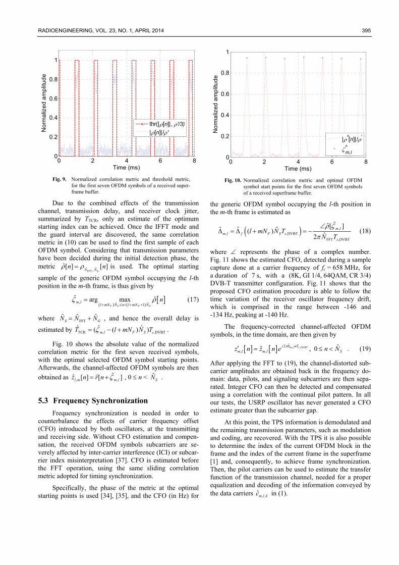
where represents the phase of a complex number. Fig. 11 shows the estimated CFO, detected during a sample capture done at a carrier frequency of fc = 658 MHz, for a duration of 7 s, with a (8K, GI 1/4, 64QAM, CR 3/4) DVB-T transmitter configuration. Fig. 11 shows that the proposed CFO estimation procedure is able to follow the time variation of the receiver oscillator frequency drift, which is comprised in the range between -146 and -134 Hz, peaking at -140 Hz.
The frequency-corrected channel-affected OFDM symbols, in the time domain, are then given by
, ,ˆ2
, ,ˆˆ , 0 m l s DVBTj nT
m l m l Sz n z n e n N . (19)
After applying the FFT to (19), the channel-distorted sub-carrier amplitudes are obtained back in the frequency do-main: data, pilots, and signaling subcarriers are then sepa-rated. Integer CFO can then be detected and compensated using a correlation with the continual pilot pattern. In all our tests, the USRP oscillator has never generated a CFO estimate greater than the subcarrier gap.
At this point, the TPS information is demodulated and the remaining transmission parameters, such as modulation and coding, are recovered. With the TPS it is also possible to determine the index of the current OFDM block in the frame and the index of the current frame in the superframe [1] and, consequently, to achieve frame synchronization. Then, the pilot carriers can be used to estimate the transfer function of the transmission channel, needed for a proper equalization and decoding of the information conveyed by the data carriers , ,ˆm l kc in (1).
396 G. BARUFFA, L. RUGINI, P. BANELLI, DESIGN AND VALIDATION OF A SDR TESTBED FOR DVB-T TRANSMISSION
0 1000 2000 3000 4000 5000 6000 7000-148
-146
-144
-142
-140
-138
-136
-134
-132
Time (ms)
Est
ima
ted
CF
O (
Hz)
Fig. 11. Temporal variation of the estimated CFO of 7 s of
received DVB-T signal adopting the configuration (8K, GI 1/4, 64QAM, CR 3/4).
5.4 Receiver Tests
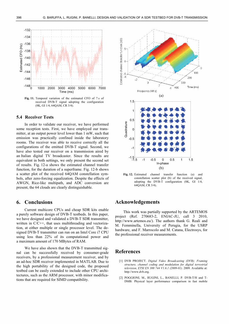
In order to validate our receiver, we have performed some reception tests. First, we have employed our trans-mitter, at an output power level lower than 1 mW, such that emission was practically confined inside the laboratory rooms. The receiver was able to receive correctly all the configurations of the emitted DVB-T signal. Second, we have also tested our receiver on a transmission aired by an Italian digital TV broadcaster. Since the results are equivalent in both settings, we only present the second set of results. Fig. 12-a shows the estimated channel transfer function, for the duration of a superframe. Fig. 12-b shows a scatter plot of the received 64QAM constellation sym-bols, after zero-forcing equalization. Despite the effects of AWGN, Rice-like multipath, and ADC conversion are present, the 64 clouds are clearly distinguishable.
6. Conclusions Current multicore CPUs and cheap SDR kits enable
a purely software design of DVB-T testbeds. In this paper, we have designed and validated a DVB-T SDR transmitter, written in C/C++, that uses multithreading and vectoriza-tion, at either multiple or single processor level. The de-signed DVB-T transmitter can run on an Intel Core i7 CPU using less than 22% of its computational power and a maximum amount of 170 MBytes of RAM.
We have also shown that the DVB-T transmitted sig-nal can be successfully received by consumer-grade receivers, by a professional measurement receiver, and by an ad-hoc SDR receiver implemented in MATLAB. Due to the high portability of the designed code, the proposed testbed can be easily extended to include other CPU archi-tectures, such as the ARM processor, with minor modifica-tions that are required for SIMD compatibility.
(a)
-1.5 -1 -0.5 0 0.5 1 1.5-1.5
-1
-0.5
0
0.5
1
1.5
In-phase
Qu
ad
ratu
re
(b)
Fig. 12. Estimated channel transfer function (a) and constellation scatter plot (b) of the received signal, adopting the DVB-T configuration (8K, GI 1/4, 64QAM, CR 3/4).
Acknowledgements
This work was partially supported by the ARTEMOS project (Ref. 270683-2, ENIAC-JU, call 3 2010, http://www.artemos.eu/). The authors thank G. Reali and M. Femminella, University of Perugia, for the USRP hardware, and F. Marrocolo and M. Catana, Electrosys, for the professional receiver measurements.
References
[1] DVB PROJECT. Digital Video Broadcasting (DVB); Framing structure, channel coding and modulation for digital terrestrial television, ETSI EN 300 744 V1.6.1 (2009-01). 2009. Available at: http://www.dvb.org.
[2] POGGIONI, M., RUGINI, L., BANELLI, P. DVB-T/H and T-DMB: Physical layer performance comparison in fast mobile

RADIOENGINEERING, VOL. 23, NO. 1, APRIL 2014 397
channels. IEEE Transactions on Broadcasting, 2009, vol. 55, no. 4, p. 719 - 730.
[3] TUTTLEBEE, W. H. Software-defined radio: facets of a developing technology. IEEE Personal Communications, 1999, vol. 6, no. 2, p. 38 - 44.
[4] PALKOVIC, M., RAGHAYAN, P., LI, M., DEJONGHE, A., VAN DER PERRE, L., CATTHOOR, F. Future software-defined radio platforms and mapping flows. IEEE Signal Processing Magazine, 2010, vol. 27, no. 2, p. 22 - 33.
[5] BLAKE, G., DRESLINSKI, R. G., MUDGE, T. A survey of multicore processors. IEEE Signal Processing Magazine, 2009, vol. 26, no. 6, p. 26 - 37.
[6] ZHENG, K., HUANG, L., LI, G., CAO, H., WANG, W., DOHLER, M. Beyond 3G evolution. IEEE Vehicular Technology Magazine, 2008, vol. 3, no. 2, p. 30 - 36.
[7] DAYANANDA, M. S., PRIYANKA, J. Managing Software Defined Radio through cloud computing. In Proceedings of the 2012 IEEE International Conference on Advanced Communication Control and Computing Technologies. Ramanathapuram (India), 2012, p. 50 - 55.
[8] GNU Radio, a free & open-source software development toolkit for SDR. Available at: http://gnuradio.org.
[9] BURGESS, D. A, SAMRA H. The Open BTS Project – an opensource GSM base station. September 2008.
[10] OPENBTS TEAM. OpenBTS. Available at: http://openbts.org/.
[11] HEIMERL, K., BREWER, E. The village base station. In Proceedings of the 4th ACM Workshop on Networked Systems for Developing Regions Systems. San Francisco (CA), 2010, p. 5 - 6.
[12] ANAND, A., JOHNSON, D. L., BELDING, E. M. VillageCell: cost effective cellular connectivity in rural areas. In Proceedings of the International Conference on Information and Communication Technologies and Development. Atlanta (GA), 2012, p. 180 - 189.
[13] AMARISOFT. Amari LTE 100, Software LTE base station on PC. Available at: http://www.amarisoft.com/.
[14] OSLD PROJECT. Open Source Long-Term Evolution (LTE) deployment. Available at: https://sites.google.com/site/osldproject/.
[15] KRATOCHVIL, T., SLANINA, M. The DVB channel coding application using the DSP development board MDS TM-13 IREF. Radioengineering, 2004, vol. 12, no. 4, p. 14 - 17.
[16] PELLEGRINI, V., BACCI, G., LUISE, M. Soft-DVB: A fully-software GNURadio-based ETSI DVB-T modulator. In Proceedings of the 5th Karlsruhe Workshop on Software Radios. Karlsruhe (Germany), 2008.
[17] ETTUS RESEARCH. USRP N200/N210 Networked Series. September 2012. Available at: https://www.ettus.com/content/files/07495_Ettus_N200-210_DS_Flyer_HR_1.pdf.
[18] GRÖNROOS, S., NYBOM, K., BJÖRKVIST, J. Complexity analysis of software defined DVB-T2 physical layer. Analog Integrated Circuits and Signal Processing, 2011, vol. 69, no. 2 - 3, p. 131 - 142.
[19] DVB PROJECT. Digital Video Broadcasting (DVB); Framing structure, channel coding and modulation for a second generation digital terrestrial television broadcasting system (DVB-T2), ETSI EN 302 755 version 1.3.1 (2012-04). 2012. Available at: http://www.dvb.org.
[20] SLIMANI, M., ROBERT, J., ZOELLNER, J. A software-based mobile DVB-T2 measurement receiver. In Proceedings of the 2012 IEEE International Symposium on Broadband Multimedia Systems and Broadcasting. Seoul (South Korea), 2012, p. 1 - 6.
[21] HASSE, P., ROBERT, J. A software-based real-time DVB-C2 receiver. In Proceedings of the 2011 IEEE International Symposium on Broadband Multimedia Systems and Broadcasting. Nuremberg (Germany), 2011, p. 1 - 6.
[22] POLAK, L., KRATOCHVIL, T. DVB-T and DVB-T2 performance in fixed terrestrial TV channels. In Proceedings of 35th International Conference on Telecommunications and Signal Processing (TSP 2012). Prague (Czech Republic), 2012, p. 725 - 729.
[23] PROAKIS, J. G. Digital Communications. 3rd ed. New York: McGraw-Hill, 1995.
[24] MICROSOFT MSDN. Intel Overview of New Instructions and Extensions, July 2009. Available at: http://msdn.microsoft.com/en-us/library/2ek511cc(v=vs.90).aspx.
[25] DE MESMAY, F., CHELLAPPA, S., FRANCHETTI, F., PÜSCHEL, M. Computer generation of efficient software Viterbi decoders. In Proceedings of the International Conference on High Performance Embedded Architectures and Compilers. Pisa (Italy), 2010, p. 353 - 368.
[26] TSENG, S.-M., KUO, Y.-C., KU, Y.-C., HSU, Y.-T. Software Viterbi decoder with SSE4 parallel processing instructions for software DVB-T receiver. In Proceedings of the IEEE International Symposium on Parallel and Distributed Processing with Applications. Chengdu (China), 2009, p. 102 - 105.
[27] YU, J.-C., SHIH, J.-Z., HSU, Y.-T., TSENG, S.-M. Reed-Solomon decoder optimization for PC-based DVB-T software radio receiver. In Proceedings of the 2011 IEEE International Conference on Consumer Electronics. Las Vegas (NV), 2011, p. 393 - 394.
[28] TAN, K., LIU H., ZHANG, J., ZHANG, Y., FANG, J., VOELKER, G. M. Sora: high-performance software radio using general-purpose multi-core processors. Communications of the ACM, 2011, vol. 54, no. 1, p. 99 - 107.
[29] WEI, X., QI, X., XIAO, L., SHI, Z., HUANG, L. Software-defined radio based on Cortex-A9. In Proceedings of 7th International ICST Conference on the Communications and Networking in China. Kunming (China), 2012, p. 758 - 761.
[30] HENTSCHEL, T., FETTWEIS, G. Sample rate conversion for software radio. IEEE Communications Magazine, 2000, vol. 38, no. 8, p. 142 - 150.
[31] GARDNER, F. M. Interpolation in digital modems—Part I: Fundamentals. IEEE Transactions on Communications, 1993, vol. 41, no. 3, p. 501 - 507.
[32] HARRIS, F. J. On the use of windows for harmonic analysis with the discrete Fourier transform. Proceedings of the IEEE, 1978, vol. 66, no. 1, p. 51 - 83.
[33] BARUFFA, G., FEMMINELLA, M., MARIANI, F., REALI, G. Protection ratio and antenna separation for DVB-T/LTE coexistence issues. IEEE Communications Letters, 2013, vol. 17, no. 8, p. 1588 - 1591.
[34] SPETH, M., FECHTEL, S., FOCK, G., MEYR, H. Optimum receiver design for OFDM-based broadband transmission—Part II: A case study. IEEE Transactions on Communications, 2001, vol. 49, no. 4, p. 571 - 578.
[35] VAN DE BEEK, J.-J., SANDELL, M., BÖRJESSON, P. O. ML estimation of time and frequency offset in OFDM systems. IEEE Transactions on Signal Processing, 1997, vol. 45, no. 7, p. 1800 - 1805.
[36] CHEN, S.-H., HE, W.-H., CHEN, H.-S., LEE, Y. Mode detection, synchronization, and channel estimation for DVB-T OFDM receiver. In Proceedings of IEEE Global Telecommunications Conference. San Francisco (CA), 2003, vol. 5, p. 2416 - 2420.

398 G. BARUFFA, L. RUGINI, P. BANELLI, DESIGN AND VALIDATION OF A SDR TESTBED FOR DVB-T TRANSMISSION
[37] RUGINI, L., BANELLI, P. BER of OFDM systems impaired by carrier frequency offset in multipath fading channels. IEEE Transactions on Wireless Communications, 2005, vol. 4, no. 5, p. 2279 - 2288.
About Authors ... Giuseppe BARUFFA was born in 1970. He received his M. Sc. in Electronic Engineering from University of Pe-rugia in 1996 and his Doctorate in Electronic Engineering in 2001, from the same University. In 2005, he visited the Signal Processing Institute, Swiss Federal Polytechnic of Lausanne, Switzerland. He is currently an Assistant Profes-sor with the Department of Engineering at the University of Perugia. His research interests include implementation aspects of digital broadcasting standards, joint source/channel coding for video, and JPEG 2000 coding for Digital Cinema. He has been also a reviewer for a num-ber of scientific journals and international conferences, and he is author of about 50 scientific papers.
Luca RUGINI was born in Perugia, Italy, in 1975. He received the Laurea degree in Electronic Engineering in 2000 and the Ph. D. degree in Telecommunications in 2003 from the University of Perugia, Perugia, Italy. In 2007, he visited Delft University of Technology, Delft, The Nether-
lands. He is currently an Assistant Professor with the De-partment of Engineering at the University of Perugia. His research interests lie in the area of signal processing for communications, with emphasis on multicarrier, cognitive radio, and cooperative techniques.
Paolo BANELLI received the Laurea degree in Electron-ics Engineering and the Ph. D. degree in Telecommunica-tions from the University of Perugia, Perugia, Italy, in 1993 and 1998, respectively. In 2005, he was appointed Associate Professor at the Department of Electronic and Information Engineering (DIEI), University of Perugia, where he has been an Assistant Professor since 1998. In 2001, he joined the SpinComm group at the Electrical and Computer Engineering Department, University of Minne-sota, Minneapolis, as a Visiting Researcher. His research interests mainly focus on signal processing for wireless communications, with emphasis on multicarrier transmis-sions, and more recently on signal processing for biomedi-cal applications, with emphasis on electrocardiography and medical ultrasounds. He is an Associate Editor of IEEE Transactions on Signal Processing and has been serving as a member of the Signal Processing for Communications and Networking Technical Committee (SPCOM-TC). He was a General Co-Chair of the IEEE International Sympo-sium on Signal Processing Advances for Wireless Com-munications 2009.