
Delta-DOR Raw Data Exchange Format - CCSDS.org Delta-DOR Raw Data Exchange Format described in this...
49
Recommendation for Space Data System Standards BLUE BOOK DELTA-DOR RAW DATA EXCHANGE FORMAT RECOMMENDED STANDARD CCSDS 506.1-B-1 June 2013
Transcript of Delta-DOR Raw Data Exchange Format - CCSDS.org Delta-DOR Raw Data Exchange Format described in this...

Recommendation for Space Data System Standards
BLUE BOOK
DELTA-DOR RAW DATA EXCHANGE
FORMAT
RECOMMENDED STANDARD
CCSDS 506.1-B-1
June 2013

Recommendation for Space Data System Standards
DELTA-DOR RAW DATA EXCHANGE
FORMAT
RECOMMENDED STANDARD
CCSDS 506.1-B-1
BLUE BOOK June 2013

RECOMMENDED STANDARD FOR DELTA-DOR RAW DATA EXCHANGE FORMAT
CCSDS 506.1-B-1 Page i June 2013
AUTHORITY
Issue: Recommended Standard, Issue 1 Date: June 2013 Location: Washington, DC, USA
This document has been approved for publication by the Management Council of the Consultative Committee for Space Data Systems (CCSDS) and represents the consensus technical agreement of the participating CCSDS Member Agencies. The procedure for review and authorization of CCSDS documents is detailed in Organization and Processes for the Consultative Committee for Space Data Systems, and the record of Agency participation in the authorization of this document can be obtained from the CCSDS Secretariat at the address below. This document is published and maintained by:
CCSDS Secretariat Space Communications and Navigation Office, 7L70 Space Operations Mission Directorate NASA Headquarters Washington, DC 20546-0001, USA

RECOMMENDED STANDARD FOR DELTA-DOR RAW DATA EXCHANGE FORMAT
CCSDS 506.1-B-1 Page ii June 2013
STATEMENT OF INTENT
The Consultative Committee for Space Data Systems (CCSDS) is an organization officially established by the management of its members. The Committee meets periodically to address data systems problems that are common to all participants, and to formulate sound technical solutions to these problems. Inasmuch as participation in the CCSDS is completely voluntary, the results of Committee actions are termed Recommended Standards and are not considered binding on any Agency.
This Recommended Standard is issued by, and represents the consensus of, the CCSDS members. Endorsement of this Recommendation is entirely voluntary. Endorsement, however, indicates the following understandings:
o Whenever a member establishes a CCSDS-related standard, this standard will be in accord with the relevant Recommended Standard. Establishing such a standard does not preclude other provisions which a member may develop.
o Whenever a member establishes a CCSDS-related standard, that member will provide other CCSDS members with the following information:
-- The standard itself.
-- The anticipated date of initial operational capability.
-- The anticipated duration of operational service.
o Specific service arrangements shall be made via memoranda of agreement. Neither this Recommended Standard nor any ensuing standard is a substitute for a memorandum of agreement.
No later than three years from its date of issuance, this Recommended Standard will be reviewed by the CCSDS to determine whether it should: (1) remain in effect without change; (2) be changed to reflect the impact of new technologies, new requirements, or new directions; or (3) be retired or canceled.
In those instances when a new version of a Recommended Standard is issued, existing CCSDS-related member standards and implementations are not negated or deemed to be non-CCSDS compatible. It is the responsibility of each member to determine when such standards or implementations are to be modified. Each member is, however, strongly encouraged to direct planning for its new standards and implementations towards the later version of the Recommended Standard.

RECOMMENDED STANDARD FOR DELTA-DOR RAW DATA EXCHANGE FORMAT
CCSDS 506.1-B-1 Page iii June 2013
FOREWORD
This document is a Recommended Standard for Delta-DOR Raw Data Exchange Format and has been prepared by the Consultative Committee for Space Data Systems (CCSDS). It has been developed via consensus of the Delta-DOR Working Group of the CCSDS Systems Engineering (SEA) area.
The Delta-DOR Raw Data Exchange Format described in this Recommended Standard is the baseline concept for Delta-DOR data interchange applications that are cross-supported between Agencies of the CCSDS.
This Recommended Standard establishes a common framework and provides a common basis for the format of Delta-DOR data exchange between space agencies. It allows implementing organizations within each Agency to proceed coherently with the development of compatible derived standards for ground systems that are within their cognizance.
Attention is drawn to the possibility that some of the elements of this document may be the subject of patent rights. CCSDS shall not be held responsible for identifying any or all such patent rights.
Through the process of normal evolution, it is expected that expansion, deletion, or modification of this document may occur. This Recommended Standard is therefore subject to CCSDS document management and change control procedures, which are defined in Organization and Processes for the Consultative Committee for Space Data Systems (CCSDS A02.1-Y-3). Current versions of CCSDS documents are maintained at the CCSDS Web site:
http://www.ccsds.org/
Questions relating to the contents or status of this document should be addressed to the CCSDS Secretariat at the address indicated on page i.

RECOMMENDED STANDARD FOR DELTA-DOR RAW DATA EXCHANGE FORMAT
CCSDS 506.1-B-1 Page iv June 2013
At time of publication, the active Member and Observer Agencies of the CCSDS were:
Member Agencies
– Agenzia Spaziale Italiana (ASI)/Italy. – Canadian Space Agency (CSA)/Canada. – Centre National d’Etudes Spatiales (CNES)/France. – China National Space Administration (CNSA)/People’s Republic of China. – Deutsches Zentrum für Luft- und Raumfahrt e.V. (DLR)/Germany. – European Space Agency (ESA)/Europe. – Federal Space Agency (FSA)/Russian Federation. – Instituto Nacional de Pesquisas Espaciais (INPE)/Brazil. – Japan Aerospace Exploration Agency (JAXA)/Japan. – National Aeronautics and Space Administration (NASA)/USA. – UK Space Agency/United Kingdom.
Observer Agencies
– Austrian Space Agency (ASA)/Austria. – Belgian Federal Science Policy Office (BFSPO)/Belgium. – Central Research Institute of Machine Building (TsNIIMash)/Russian Federation. – China Satellite Launch and Tracking Control General, Beijing Institute of Tracking
and Telecommunications Technology (CLTC/BITTT)/China. – Chinese Academy of Sciences (CAS)/China. – Chinese Academy of Space Technology (CAST)/China. – Commonwealth Scientific and Industrial Research Organization (CSIRO)/Australia. – CSIR Satellite Applications Centre (CSIR)/Republic of South Africa. – Danish National Space Center (DNSC)/Denmark. – Departamento de Ciência e Tecnologia Aeroespacial (DCTA)/Brazil. – European Organization for the Exploitation of Meteorological Satellites
(EUMETSAT)/Europe. – European Telecommunications Satellite Organization (EUTELSAT)/Europe. – Geo-Informatics and Space Technology Development Agency (GISTDA)/Thailand. – Hellenic National Space Committee (HNSC)/Greece. – Indian Space Research Organization (ISRO)/India. – Institute of Space Research (IKI)/Russian Federation. – KFKI Research Institute for Particle & Nuclear Physics (KFKI)/Hungary. – Korea Aerospace Research Institute (KARI)/Korea. – Ministry of Communications (MOC)/Israel. – National Institute of Information and Communications Technology (NICT)/Japan. – National Oceanic and Atmospheric Administration (NOAA)/USA. – National Space Agency of the Republic of Kazakhstan (NSARK)/Kazakhstan. – National Space Organization (NSPO)/Chinese Taipei. – Naval Center for Space Technology (NCST)/USA. – Scientific and Technological Research Council of Turkey (TUBITAK)/Turkey. – Space and Upper Atmosphere Research Commission (SUPARCO)/Pakistan. – Swedish Space Corporation (SSC)/Sweden. – United States Geological Survey (USGS)/USA.

RECOMMENDED STANDARD FOR DELTA-DOR RAW DATA EXCHANGE FORMAT
CCSDS 506.1-B-1 Page v June 2013
DOCUMENT CONTROL
Document Title Date Status
CCSDS 506.1-B-1
Delta-DOR Raw Data Exchange Format, Recommended Standard, Issue 1
June 2013 Current issue
RECOMMENDED STANDARD FOR DELTA-DOR RAW DATA EXCHANGE FORMAT
CCSDS 506.1-B-1 Page vi June 2013
CONTENTS
Section Page
1 INTRODUCTION.......................................................................................................... 1-1 1.1 PURPOSE ............................................................................................................... 1-1 1.2 SCOPE AND APPLICABILITY............................................................................ 1-1 1.3 CONVENTIONS AND DEFINITIONS ................................................................ 1-2 1.4 COMMON DELTA-DOR TERMINOLOGY ........................................................ 1-3 1.5 STRUCTURE OF THE DOCUMENT .................................................................. 1-3 1.6 REFERENCES ....................................................................................................... 1-4
2 OVERVIEW ................................................................................................................... 2-1
2.1 GENERAL .............................................................................................................. 2-1 2.2 THE DELTA-DOR TECHNIQUE ......................................................................... 2-1 2.3 THE NEED FOR RAW DATA INTERCHANGE ................................................ 2-4 2.4 CONVENTIONS FOR IDENTIFIERS .................................................................. 2-4
3 RAW DATA EXCHANGE FORMAT BASIC STRUCTURE AND CONTENT ... 3-1
3.1 OVERVIEW ........................................................................................................... 3-1 3.2 DELTA-DOR FILES .............................................................................................. 3-1
4 OBSERVATION FILE STRUCTURE AND CONTENT ......................................... 4-1
4.1 GENERAL .............................................................................................................. 4-1 4.2 CONTENT OF THE OBSERVATION HEADER SECTION ............................... 4-2 4.3 CONTENT OF SCAN SECTION .......................................................................... 4-3 4.4 CONTENT OF THE ENDING SECTION ............................................................. 4-6
5 PRODUCT FILE STRUCTURE AND CONTENT ................................................... 5-1
5.1 GENERAL .............................................................................................................. 5-1 5.2 PRODUCT FILE RECORD HEADER DESCRIPTION ....................................... 5-3 5.3 PRODUCT FILE RECORD DATA DESCRIPTION .......................................... 5-15
6 FILE NAMING CONVENTIONS ............................................................................... 6-1
6.1 GENERAL .............................................................................................................. 6-1 6.2 FILE NAMES ......................................................................................................... 6-1
ANNEX A PARAMETERS THAT NEED CONVENTIONS TO BE
SPECIFIED (NORMATIVE) ...................................................................... A-1
RECOMMENDED STANDARD FOR DELTA-DOR RAW DATA EXCHANGE FORMAT
CCSDS 506.1-B-1 Page vii June 2013
CONTENTS (continued)
Section Page
ANNEX B SECURITY, SANA, AND PATENT CONSIDERATIONS (INFORMATIVE) ..........................................................................................B-1
ANNEX C ABBREVIATIONS AND ACRONYMS (INFORMATIVE) .................... C-1 ANNEX D INFORMATIVE REFERENCES (INFORMATIVE) .............................. D-1 ANNEX E EXAMPLE OF RDEF OBSERVATION FILE (INFORMATIVE) .........E-1
Figure
2-1 Delta-DOR Observation Geometry .............................................................................. 2-2 4-1 General Structure of the RDEF Observation File ......................................................... 4-1 5-1 General Structure of one Product File Record .............................................................. 5-1 5-2 Detailed Structure of the Product File Record .............................................................. 5-2 5-3 General Structure of the Header ................................................................................... 5-4 5-4 General Structure of the Data Section of the Record .................................................. 5-17
Table
4-1 Description of the Scan Line ........................................................................................ 4-4 4-2 Description of the Product File Line............................................................................. 4-5 5-1 Product File Header ...................................................................................................... 5-8 5-2 Sample 32-Bit Word Packing ..................................................................................... 5-15
RECOMMENDED STANDARD FOR DELTA-DOR RAW DATA EXCHANGE FORMAT
CCSDS 506.1-B-1 Page 1-1 June 2013
1 INTRODUCTION
1.1 PURPOSE
Delta-DOR (Delta Differential One-Way Ranging) is a Very Long Baseline Interferometry (VLBI) technique that can be used in conjunction with Doppler and ranging data to improve spacecraft navigation by more efficiently determining spacecraft angular position in the plane of sky. It involves the use of multiple ground stations, possibly belonging to different agencies, for simultaneous acquisition of either spacecraft or quasar signals (see reference [D2]).
This Delta-DOR Raw Data Exchange Format (RDEF) Recommended Standard specifies a standard format for use in exchanging Delta-DOR raw data among space agencies. Delta-DOR raw data exchange is required every time the data correlation involves at least one participating station not belonging to the agency responsible for the correlation.This document includes specifications on the parameter fields that the data format has been designed to meet. For exchanges where these specifications do not capture the needs of the participating agencies another mechanism may be selected.
1.2 SCOPE AND APPLICABILITY
This Recommended Standard contains the specification for a Delta-DOR RDEF designed for applications involving Delta-DOR raw data interchange among space agencies.
The format here specified can be equally used for collecting and exchanging more general open loop raw data.
This data format is suited to inter-agency exchanges that involve automated interaction. The attributes of the RDEF make it primarily suitable for use in computer-to-computer communication.
The characteristics of the data recording (sampling rate and quantization) are defined within the RDEF. There is no definition of accuracy for raw Delta-DOR data, and hence no assessment of accuracy is provided in the exchange format. An assessment of accuracy for reduced Delta-DOR measurements is outside the scope of this Recommended Standard. This Recommended Standard defines only the data format and content, but not the means for its transmission. The method of transmitting the data among partners is beyond the scope of this document. Data transmission could be based on a CCSDS data transfer protocol, file-based transfer protocol such as SFTP, stream-oriented media, or other secure transmission mechanism. In general, the transmission mechanism shall not place constraints on the technical data content of an RDEF.

RECOMMENDED STANDARD FOR DELTA-DOR RAW DATA EXCHANGE FORMAT
CCSDS 506.1-B-1 Page 1-2 June 2013
1.3 CONVENTIONS AND DEFINITIONS
1.3.1 NOMENCLATURE
1.3.1.1 Normative Text
The following conventions apply for the normative specifications in this Recommended Standard:
a) the words ‘shall’ and ‘must’ imply a binding and verifiable specification;
b) the word ‘should’ implies an optional, but desirable, specification;
c) the word ‘may’ implies an optional specification;
d) the words ‘is’, ‘are’, and ‘will’ imply statements of fact.
NOTE – These conventions do not imply constraints on diction in text that is clearly informative in nature.
1.3.1.2 Informative Text
In the normative sections of this document, informative text is set off from the normative specifications either in notes or under one of the following subsection headings:
– Overview;
– Background;
– Rationale;
– Discussion.
1.3.2 UNIT NOTATION
The following conventions for unit notations apply throughout this Recommended Standard. Insofar as possible, an effort has been made to use units that are part of the International System of Units (SI Units); units are either SI base units, SI derived units, or units outside the SI that are accepted for use with the SI (see reference [2]), e.g.,
Hz: Hertz
s: second
1.3.3 BIT AND BYTE ORDERING In this document, the following convention is used to identify each bit in an 8-bit byte. The first bit in the byte (i.e., the most right justified when drawing figures and tables) is defined to be ‘Bit 1’, the following bit is defined to be ‘Bit 2’, and so on up to ‘Bit 8’.

RECOMMENDED STANDARD FOR DELTA-DOR RAW DATA EXCHANGE FORMAT
CCSDS 506.1-B-1 Page 1-3 June 2013
Byte ordering follows the convention of starting with Byte 1 (i.e., the most right justified when drawing figures and tables) and increasing to the left.
1.4 COMMON DELTA-DOR TERMINOLOGY
Part of the standardization process involves the agreement on common interagency terminology and definitions that apply to interagency Delta-DOR. The following conventions apply throughout this Recommended Standard:
baseline: The vector joining two tracking stations.
channel: A slice of the frequency spectrum containing a spacecraft or quasar signal.
raw data: Time-ordered samples of received radio signal voltage.
sample: Instantaneous measurement of a radio frequency signal voltage.
scan: An observation of a radio source, with typical duration of a few minutes.
session: The time period of the Delta-DOR measurement including several scans.
meteo data: meteorological data (consisting of pressure, temperature, and relative humidity).
1.5 STRUCTURE OF THE DOCUMENT
Section 2 provides a general overview of the Delta-DOR technique and introduces the need of the raw data exchange.
Section 3 describes the basic structure and contents of the CCSDS-recommended RDEF for Delta-DOR.
Section 4 provides a description of the RDEF observation file.
Section 5 provides details on the RDEF product file.
Section 6 describes the RDEF file naming conventions.
Annex A lists the parameters for which conventions need to be specified.
Annex B discusses security aspects for the RDEF.
Annex C is a list of abbreviations and acronyms applicable to the document.
Annex D provides a list of informative references.
Annex E provides an example of a RDEF Observation File.
RECOMMENDED STANDARD FOR DELTA-DOR RAW DATA EXCHANGE FORMAT
CCSDS 506.1-B-1 Page 1-4 June 2013
1.6 REFERENCES
The following publications contain provisions which, through reference in this text, constitute provisions of this document. At the time of publication, the editions indicated were valid. All publications are subject to revision, and users of this document are encouraged to investigate the possibility of applying the most recent editions of the publications indicated below. The CCSDS Secretariat maintains a register of currently valid CCSDS publications.
[1] Information Technology—8-Bit Single-Byte Coded Graphic Character Sets—Part 1: Latin Alphabet No. 1. International Standard, ISO/IEC 8859-1:1998. Geneva: ISO, 1998.
[2] “The International System of Units (SI).” Bureau International des Poids et Mesures (BIPM). <http://www.bipm.org/en/si>
[3] IEEE Standard for Floating-Point Arithmetic. 2nd ed. IEEE Std. 754-2008. New York: IEEE, 2008.
[4] Time Code Formats. Recommendation for Space Data System Standards, CCSDS 301.0-B-4. Blue Book. Issue 4. Washington, D.C.: CCSDS, November 2010.
[5] Delta-Differential One Way Ranging (Delta-DOR) Operations. Recommendation for Space Data System Practices, CCSDS 506.0-M-1. Magenta Book. Issue 1. Washington, D.C.: CCSDS, April 2011.
NOTE – Informative references are provided in annex D.

RECOMMENDED STANDARD FOR DELTA-DOR RAW DATA EXCHANGE FORMAT
CCSDS 506.1-B-1 Page 2-1 June 2013
2 OVERVIEW
2.1 GENERAL
This section provides a high-level overview of the Delta-DOR technique. More details on the technique can be found in references [5] and [D2]. In particular, reference [D2] provides a detailed description of the Delta-DOR technique, including guidelines for DOR tone spectra, guidelines for selecting reference sources, applicable foundation equations, and a discussion of error sources and measurement accuracy that are not germane to the data exchange recommendation presented in this document.
2.2 THE DELTA-DOR TECHNIQUE
Very Long Baseline Interferometry (VLBI) is a technique that allows determination of angular position for distant radio sources by measuring the geometric time delay between received radio signals at two geographically separated stations. The observed time delay is a function of the known baseline vector joining the two radio antennas and the direction to the radio source.
An application of VLBI is spacecraft navigation in space missions where delay measurements of a spacecraft radio signal are compared against similar delay measurements of angularly nearby quasar radio signals. In the case where the spacecraft measurements are obtained from the phases of tones emitted from the spacecraft, first detected separately at each station, and then differenced, this application of VLBI is known as Delta Differential One-Way Ranging (‘Delta-DOR’ or ‘∆DOR’). (See figure 2-1.) Even though data acquisition and processing are not identical for the spacecraft and quasar, both types of measurements can be interpreted as time delay measurements, and they have similar information content and similar sensitivity to sources of error (see reference [D2]). The data produced in such a measurement session are complementary to Doppler and ranging data.

RECOMMENDED STANDARD FOR DELTA-DOR RAW DATA EXCHANGE FORMAT
CCSDS 506.1-B-1 Page 2-2 June 2013
τ
CorrelatorBaseline B
θ
τ= B·cos(θ)/c
spac
ecraf
t dela
y τ
c = speed of light
Spacecraft
Quasar
Figure 2-1 Delta-DOR Observation Geometry
To enable a Delta-DOR measurement, a spacecraft must emit several tones or other signal components spanning at least a few MHz. The characteristics of the tones are selected based on the requirements for phase ambiguity resolution, measurement accuracy, efficient use of spacecraft signal power, efficient use of ground tracking resources, and the frequency allocation for space research.
The Delta-DOR technique requires that the same quasar and spacecraft be tracked essentially simultaneously during the same tracking pass, at two distinct radio antennas. Normally, a Delta-DOR pass consists of three or more scans of data recording, each of a few minutes duration. A scan consists of pointing the antennas to one radio source and recording the signal. The antennas must slew to another radio source for the next scan, and so on. The observing sequence is spacecraft-quasar-spacecraft, quasar-spacecraft-quasar, or a longer sequence of alternating observations, depending on the characteristics of the radio sources and the objectives of the measurement session. A minimum of three scans is required to eliminate clock-epoch and clock-rate offsets and then measure spacecraft angular position. Normally a three-scan sequence is repeated several times. Once collected, the received signals are brought to a common site and correlated. A Delta-DOR observable is generated from a differential one-way range measurement made between the spacecraft and the two ground antennas, and by a measurement of the difference in time of arrival, at the same two
RECOMMENDED STANDARD FOR DELTA-DOR RAW DATA EXCHANGE FORMAT
CCSDS 506.1-B-1 Page 2-3 June 2013
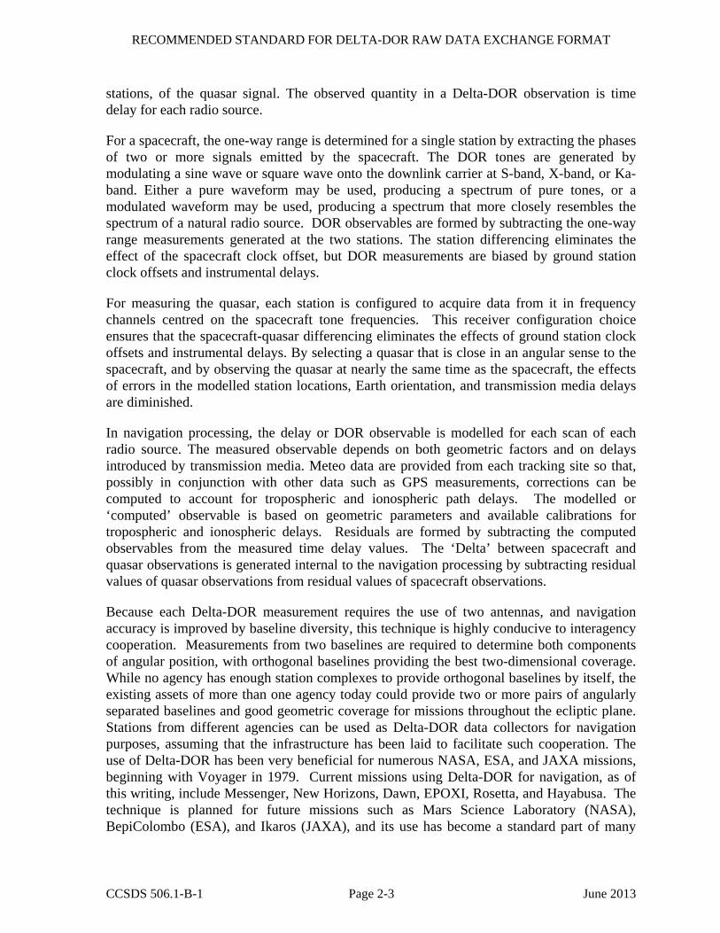
stations, of the quasar signal. The observed quantity in a Delta-DOR observation is time delay for each radio source.
For a spacecraft, the one-way range is determined for a single station by extracting the phases of two or more signals emitted by the spacecraft. The DOR tones are generated by modulating a sine wave or square wave onto the downlink carrier at S-band, X-band, or Ka-band. Either a pure waveform may be used, producing a spectrum of pure tones, or a modulated waveform may be used, producing a spectrum that more closely resembles the spectrum of a natural radio source. DOR observables are formed by subtracting the one-way range measurements generated at the two stations. The station differencing eliminates the effect of the spacecraft clock offset, but DOR measurements are biased by ground station clock offsets and instrumental delays.
For measuring the quasar, each station is configured to acquire data from it in frequency channels centred on the spacecraft tone frequencies. This receiver configuration choice ensures that the spacecraft-quasar differencing eliminates the effects of ground station clock offsets and instrumental delays. By selecting a quasar that is close in an angular sense to the spacecraft, and by observing the quasar at nearly the same time as the spacecraft, the effects of errors in the modelled station locations, Earth orientation, and transmission media delays are diminished.
In navigation processing, the delay or DOR observable is modelled for each scan of each radio source. The measured observable depends on both geometric factors and on delays introduced by transmission media. Meteo data are provided from each tracking site so that, possibly in conjunction with other data such as GPS measurements, corrections can be computed to account for tropospheric and ionospheric path delays. The modelled or ‘computed’ observable is based on geometric parameters and available calibrations for tropospheric and ionospheric delays. Residuals are formed by subtracting the computed observables from the measured time delay values. The ‘Delta’ between spacecraft and quasar observations is generated internal to the navigation processing by subtracting residual values of quasar observations from residual values of spacecraft observations.
Because each Delta-DOR measurement requires the use of two antennas, and navigation accuracy is improved by baseline diversity, this technique is highly conducive to interagency cooperation. Measurements from two baselines are required to determine both components of angular position, with orthogonal baselines providing the best two-dimensional coverage. While no agency has enough station complexes to provide orthogonal baselines by itself, the existing assets of more than one agency today could provide two or more pairs of angularly separated baselines and good geometric coverage for missions throughout the ecliptic plane. Stations from different agencies can be used as Delta-DOR data collectors for navigation purposes, assuming that the infrastructure has been laid to facilitate such cooperation. The use of Delta-DOR has been very beneficial for numerous NASA, ESA, and JAXA missions, beginning with Voyager in 1979. Current missions using Delta-DOR for navigation, as of this writing, include Messenger, New Horizons, Dawn, EPOXI, Rosetta, and Hayabusa. The technique is planned for future missions such as Mars Science Laboratory (NASA), BepiColombo (ESA), and Ikaros (JAXA), and its use has become a standard part of many

RECOMMENDED STANDARD FOR DELTA-DOR RAW DATA EXCHANGE FORMAT
CCSDS 506.1-B-1 Page 2-4 June 2013
mission navigation plans. CCSDS standardization will help expand the use of the technique by allowing interagency cross support.
2.3 THE NEED FOR RAW DATA INTERCHANGE
When performing a Delta-DOR measurement involving two (or more) agencies, raw Delta-DOR data must be exchanged at least between one of the agencies that has acquired the data and the agency that runs the correlation process and provides the results. The need of the raw data exchange intrinsically comes with the characteristics of the measurement that, being an interferometric technique, calls for the correlation of at least two data streams simultaneously acquired.
Raw Delta-DOR data are not the only data being exchanged during an interagency Delta-DOR session. Other data (such as tracking data messages, including meteo data, and orbit ephemeris messages) must be exchanged among agencies. Such data are objects of other CCSDS standards (see references [D9], [D10], [D11]) and are not discussed in the present Recommended Standard. The transfer of information other than Delta-DOR raw data is discussed in the Delta-DOR Operations Magenta Book (reference [5]) and will not be included here.
2.4 CONVENTIONS FOR IDENTIFIERS
This Recommended Standard does not specify the conventions to be used for identifiers of tracking stations, spacecraft, and radio sources. While these objects must be identified to give meaning to the data, it is outside the scope of this Recommended Standard to specify the names to be used. These parameters are described as they are introduced throughout the Recommended Standard and are collected in annex A. Conventions to be used for such parameters should be negotiated among the participating agencies and formalized as specified in annex A of reference [5].
If accessible and agreed catalogues for identifiers of tracking stations, spacecraft, and radio sources are available, they should be preferentially used.

RECOMMENDED STANDARD FOR DELTA-DOR RAW DATA EXCHANGE FORMAT
CCSDS 506.1-B-1 Page 3-1 June 2013
3 RAW DATA EXCHANGE FORMAT BASIC STRUCTURE AND CONTENT
3.1 OVERVIEW
Delta-DOR RDEF is realized with two types of files: an Observation File made of a sequence of ASCII text lines and a Product File made of a sequence of binary data records. Both files are needed to properly perform the correlation.
The Observation File contains information about the Delta-DOR measurement session.
The Product File contains data collected during the Delta-DOR measurement session.
3.2 DELTA-DOR FILES
3.2.1 OBSERVATION FILE
There shall be one Observation File for each tracking station and for each measurement session. The Observation File shall be made of a sequence of ASCII text lines (reference [1]).
3.2.2 PRODUCT FILE
3.2.2.1 The content of the Product File shall consist of time-ordered records each containing two basic types of data structure:
– A Header part;
– A Data part.
3.2.2.2 A Product File shall contain data for a single tracking station.
3.2.2.3 A Product File shall contain data for a single Delta-DOR scan (therefore either spacecraft or quasar data).
3.2.2.4 A Product File shall contain data for a single frequency channel.
RECOMMENDED STANDARD FOR DELTA-DOR RAW DATA EXCHANGE FORMAT
CCSDS 506.1-B-1 Page 4-1 June 2013
4 OBSERVATION FILE STRUCTURE AND CONTENT
4.1 GENERAL
NOTE – The Observation File contains parameters that are needed to describe the data recording session and to support data correlation.
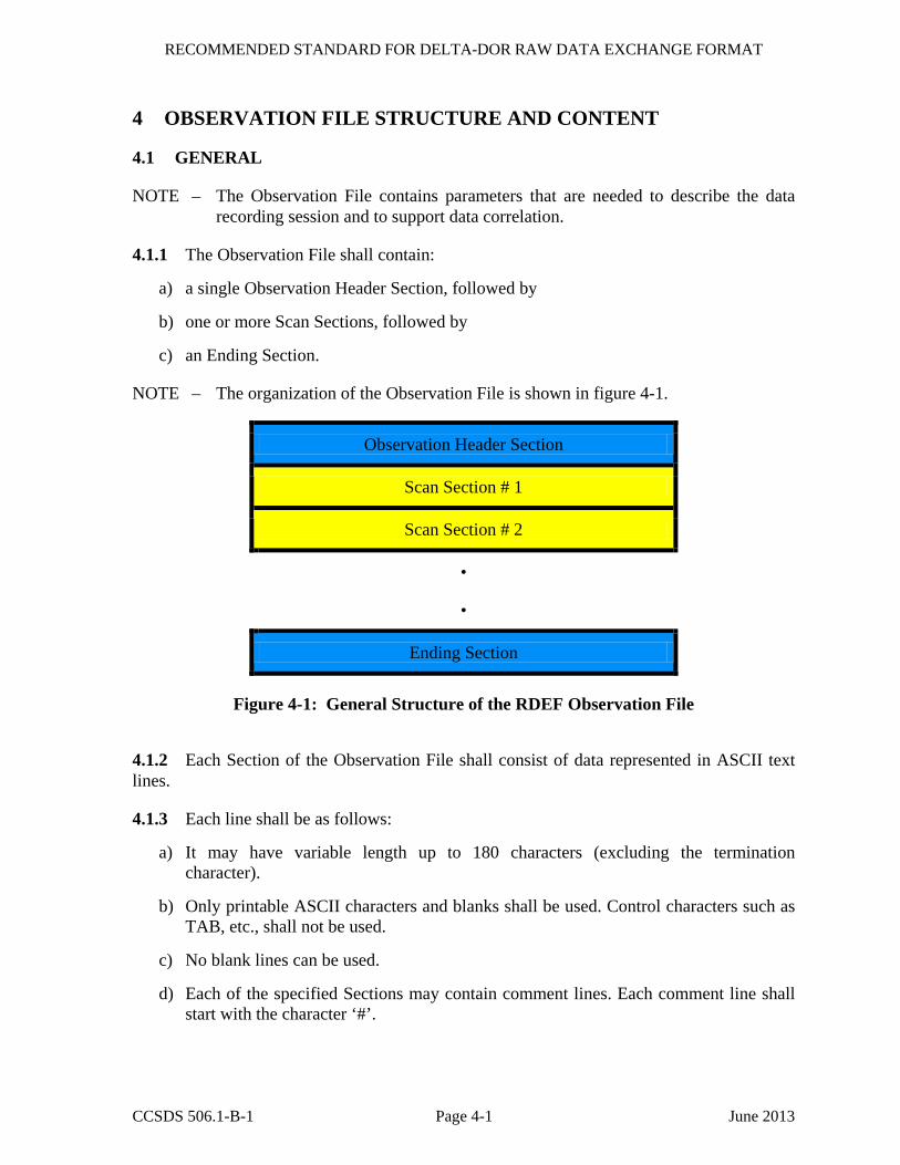
4.1.1 The Observation File shall contain:
a) a single Observation Header Section, followed by
b) one or more Scan Sections, followed by
c) an Ending Section.
NOTE – The organization of the Observation File is shown in figure 4-1.
Observation Header Section
Scan Section # 1
Scan Section # 2
•
•
Ending Section
Figure 4-1: General Structure of the RDEF Observation File
4.1.2 Each Section of the Observation File shall consist of data represented in ASCII text lines.
4.1.3 Each line shall be as follows:
a) It may have variable length up to 180 characters (excluding the termination character).
b) Only printable ASCII characters and blanks shall be used. Control characters such as TAB, etc., shall not be used.
c) No blank lines can be used.
d) Each of the specified Sections may contain comment lines. Each comment line shall start with the character ‘#’.
RECOMMENDED STANDARD FOR DELTA-DOR RAW DATA EXCHANGE FORMAT
CCSDS 506.1-B-1 Page 4-2 June 2013
e) The first character in each line of an Observation File shall identify the type of information contained in that line.
NOTE – Details regarding each line type are provided in 4.1.4 and in the following subsections, as appropriate.
f) One or more ‘blank’ characters shall be used to separate each of the various items within each line.
g) Each line shall be terminated by a single Line Feed or a single Carriage Return or a Carriage Return/Line Feed pair or a Line Feed/Carriage Return pair.
4.1.4 Each Section (except for the Ending Section) shall end with a line starting with character ‘Z’.
4.2 CONTENT OF THE OBSERVATION HEADER SECTION
4.2.1 The Observation Header Section shall consist of as many lines as are needed.
4.2.2 The Observation Header Section shall contain a version line. This line shall start with the character ‘V’.
4.2.3 The structure of the line shall be as follows:
V VERSION = <version>
4.2.4 where <version> is the version identifier, integer. The version number shall be synchronised with the one given in the Product File
4.2.5 The Observation Header Section shall contain a single receive station line. This line shall start with the character ‘R’.
4.2.6 The structure of the line shall be as follows:
R STATION = <station>
4.2.7 where <station> is the station identifier, four ASCII characters long. The Observation Header Section may optionally contain a single transmitting station line. This line shall start with the character ‘T’.
4.2.8 The structure of the line shall be as follows:
T STATION = <station>
where <station> is the station identifier, 4 ASCII characters long.
4.2.9 If the data are one-way, the transmitting station line shall be omitted.

RECOMMENDED STANDARD FOR DELTA-DOR RAW DATA EXCHANGE FORMAT
CCSDS 506.1-B-1 Page 4-3 June 2013
4.3 CONTENT OF SCAN SECTION
NOTE – The Scan Section describes the observation and provides the list of Product File(s) associated with the scan.
4.3.1 A Scan Section shall contain a single scan line followed by one or more Product File lines.
4.3.2 To improve readability, the scan Section should also contain comment lines providing labels for the scan line and the Product File lines.
4.3.3 The scan line shall start with character ‘S’.
4.3.4 The structure of the scan line shall be as follows:
S <scan_num> <src_id> <start_time> <stop_time> <ra> <dec> <tfreq>
NOTE – The parameters are defined in table 4-1.

RECOMMENDED STANDARD FOR DELTA-DOR RAW DATA EXCHANGE FORMAT
CCSDS 506.1-B-1 Page 4-4 June 2013
Table 4-1: Description of the Scan Line
Item Name Item Description Format Units/ Precision/Range SCAN_NUM Identifies the scan number, in a
progressive order. 3 digit integer
No units, range 001-999
SRC_ID Specifies the source, SC ID or Quasar ID.
Up to 16 ASCII characters. Syntax is referenced in annex A.
No units, up to 16 characters for quasar, 4 characters for spacecraft
START_TIME
Specifies the nominal start time for the scan.
YYYY-DDDThh:mm:ss
UTC year, day of the year, hour/minute/second, precision=1 s, range is unlimited Time format as per reference [4], ASCII time code B
STOP_TIME Specifies the nominal stop time for the scan.
YYYY-DDDThh:mm:ss
UTC year, day of the year, hour/minute/second, precision=1 s, range is unlimited Time format as per reference [4], ASCII time code B
RA Specifies the Right Ascension of the source. Source position is referred to true equator and equinox of date and it is corrected for aberration.
Decimal notation
Degrees, range 0 to 360, decimal notation with no more than 16 significant digits. This field may be filled with number 999, meaning that no Right Ascension is provided.
DEC Specifies the Declination of the source. Source position is referred to true equator and equinox of date and it is corrected for aberration.
Decimal notation
Degrees, range -90 to +90, decimal notation with no more than 16 significant digits. This field may be filled with number 999, meaning that no Declination is provided.
TFREQ Specifies the Transmitted Frequency if the source is a Spacecraft; if not, TFREQ= 0.
Decimal notation
Hz, decimal notation with no more than 16 significant digits.
4.3.5 The Product File line shall start with character ‘D’.
4.3.6 There shall be a Product File line for each frequency channel.

RECOMMENDED STANDARD FOR DELTA-DOR RAW DATA EXCHANGE FORMAT
CCSDS 506.1-B-1 Page 4-5 June 2013
4.3.7 The structure of each Product File line shall be as follows:
D <datafile> <coherence_flag> <dor_mult> <fsub> <harmonic>
NOTE – The parameters are defined in table 4-2.
Table 4-2: Description of the Product File Line
Item Name Item Description Format Units/ Precision/Range
DATAFILE Specifies the name of a Product File recording
39 ASCII characters, as specified in 6.2
No units
COHERENCE_FLAG
Identifies whether or not the signal is coherent with the carrier. If True the fields DOR-MULT and HARMONIC are used to compute the tone frequency. If False the fields FSUB and HARMONIC are used to compute the tone frequency.
1 ASCII character
No units, ‘T’ for True, ‘F’ for False
DOR_MULT Specifies two integers used as the numerator and denominator of a number, which represents the fundamental tone as a fraction of the TFREQ, in case COHERENCE-FLAG=‘T’; example: 11/18440. In case COHERENCE-FLAG=‘F’, any number is allowed.
A fraction of two integer numbers
No units
FSUB Specifies the fundamental subcarrier frequency, in all cases where such subcarrier is not coherent with the carrier. In case COHERENCE-FLAG=‘T’, any value is allowed.
Decimal notation
Hz, decimal notation with no more than 16 significant digits
HARMONIC Specifies the subcarrier or coherent tone harmonic number.
Integer No units

RECOMMENDED STANDARD FOR DELTA-DOR RAW DATA EXCHANGE FORMAT
CCSDS 506.1-B-1 Page 4-6 June 2013
4.4 CONTENT OF THE ENDING SECTION
4.4.1 The Ending Section shall contain an end line, optionally preceded by one or more log lines.
4.4.2 Each log line shall begin with the character ‘F’ and may contain information on how to retrieve receiver messages, data, and log.
4.4.3 The end line shall begin with the ‘E’ character and have the following format:
E *=END=*
NOTE – A sample Observation File is shown in annex E.

RECOMMENDED STANDARD FOR DELTA-DOR RAW DATA EXCHANGE FORMAT
CCSDS 506.1-B-1 Page 5-1 June 2013
5 PRODUCT FILE STRUCTURE AND CONTENT
5.1 GENERAL
5.1.1 The Product File shall consist of several Records, each one containing exactly one second of data and related information to correlate such second of data.
5.1.2 Each Record shall consist of data represented in binary format. It shall be made of two Sections:
a) The Header Section (see 5.2)
b) The Data Section (see 5.3)
NOTE – Figure 5-1 shows the general structure of one Product File Record.
Data section
Header section
Record representingone second of observation
Figure 5-1: General Structure of one Product File Record
5.1.3 Each Product File shall contain data for one scan, one channel, and one station (i.e., for a typical 2-station Delta-DOR sequence with 3 scans and 4 channels there will be 24 files).
5.1.4 The length of the Header Section is fixed as per figure 5-2; the length of the Data Section is variable and shall be determined by the sample rate and sample size of the recorded data. The total length of the Data Section shall be fully determined by the information written in the Header Section.
5.1.5 The byte order of all integer and floating point values occupying more than one byte contained in the Product File shall be written as Little Endian, with an atomic element size of 8 bits.
NOTE – The structure of a Record is shown in figure 5-2.

RECOM
MEN
DED
STAN
DA
RD
FOR D
ELTA-D
OR R
AW
DA
TA EX
CHA
NG
E FORM
AT
CC
SDS 506.1-B
-1 Page 5-2
June 2013
BYTE 4 BYTE 3 BYTE 2 BYTE 1 BIT +--+--+--+--+--+--+--+--+--+--+--+--+--+--+--+--+--+--+--+--+--+--+--+--+--+--+--+--+--+--+--+--+ |8 |7 |6 |5 |4 |3 |2 |1 |8 |7 |6 |5 |4 |3 |2 |1 |8 |7 |6 |5 |4 |3 |2 |1 |8 |7 |6 |5 |4 |3 |2 |1 | +--+--+--+--+--+--+--+--+--+--+--+--+--+--+--+--+--+--+--+--+--+--+--+--+--+--+--+--+--+--+--+--+
BYTE 4| |BYTE 1 | | ... HEADER SECTION ...
... [176 Bytes] ... | |
176 | |173 +--+--+--+--+--+--+--+--+--+--+--+--+--+--+--+--+--+--+--+--+--+--+--+--+--+--+--+--+--+--+--+--+
180 | |177 | | ... DATA SECTION ... ... [N-176 Bytes] ... | |
N | |N-3 +--+--+--+--+--+--+--+--+--+--+--+--+--+--+--+--+--+--+--+--+--+--+--+--+--+--+--+--+--+--+--+--+
N = total number of bytes per record
Figure 5-2: Detailed Structure of the Product File Record

RECOMMENDED STANDARD FOR DELTA-DOR RAW DATA EXCHANGE FORMAT
CCSDS 506.1-B-1 Page 5-3 June 2013
5.2 PRODUCT FILE RECORD HEADER DESCRIPTION
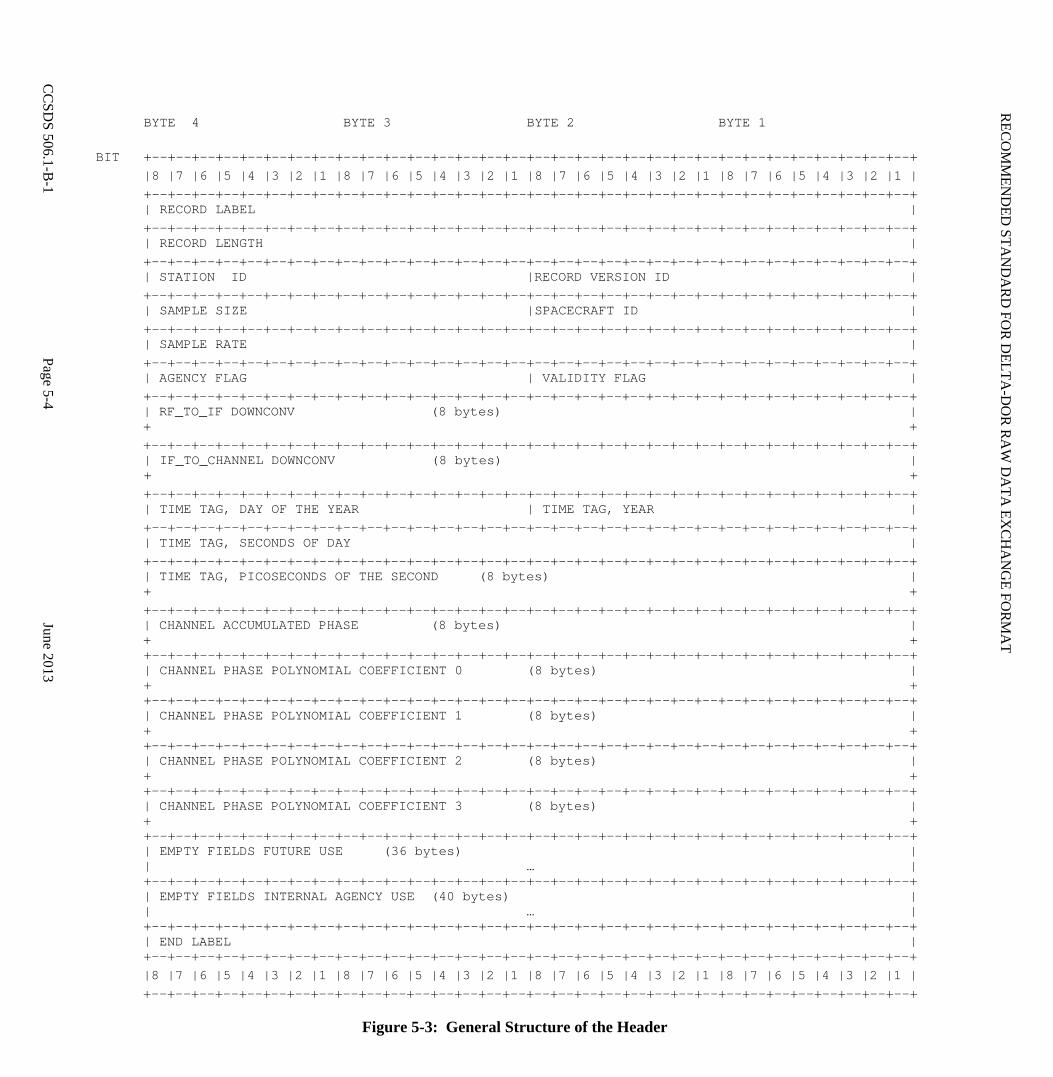
5.2.1 The Header Section of the Record shall contain information related to the station configuration and the basic parameters used in the Record itself (see 5.2.2).
The structure of the Header shall be fixed, as per figure 5-3. The Header contains 23 parameters and two empty fields for future expansion.
RECOM
MEN
DED
STAN
DA
RD
FOR D
ELTA-D
OR R
AW
DA
TA EX
CHA
NG
E FORM
AT
CC
SDS 506.1-B
-1 Page 5-4
June 2013
BYTE 4 BYTE 3 BYTE 2 BYTE 1
BIT +--+--+--+--+--+--+--+--+--+--+--+--+--+--+--+--+--+--+--+--+--+--+--+--+--+--+--+--+--+--+--+--+ |8 |7 |6 |5 |4 |3 |2 |1 |8 |7 |6 |5 |4 |3 |2 |1 |8 |7 |6 |5 |4 |3 |2 |1 |8 |7 |6 |5 |4 |3 |2 |1 | +--+--+--+--+--+--+--+--+--+--+--+--+--+--+--+--+--+--+--+--+--+--+--+--+--+--+--+--+--+--+--+--+ | RECORD LABEL | +--+--+--+--+--+--+--+--+--+--+--+--+--+--+--+--+--+--+--+--+--+--+--+--+--+--+--+--+--+--+--+--+ | RECORD LENGTH | +--+--+--+--+--+--+--+--+--+--+--+--+--+--+--+--+--+--+--+--+--+--+--+--+--+--+--+--+--+--+--+--+
| STATION ID |RECORD VERSION ID | +--+--+--+--+--+--+--+--+--+--+--+--+--+--+--+--+--+--+--+--+--+--+--+--+--+--+--+--+--+--+--+--+
| SAMPLE SIZE |SPACECRAFT ID | +--+--+--+--+--+--+--+--+--+--+--+--+--+--+--+--+--+--+--+--+--+--+--+--+--+--+--+--+--+--+--+--+ | SAMPLE RATE | +--+--+--+--+--+--+--+--+--+--+--+--+--+--+--+--+--+--+--+--+--+--+--+--+--+--+--+--+--+--+--+--+ | AGENCY FLAG | VALIDITY FLAG | +--+--+--+--+--+--+--+--+--+--+--+--+--+--+--+--+--+--+--+--+--+--+--+--+--+--+--+--+--+--+--+--+
| RF_TO_IF DOWNCONV (8 bytes) | + + +--+--+--+--+--+--+--+--+--+--+--+--+--+--+--+--+--+--+--+--+--+--+--+--+--+--+--+--+--+--+--+--+
| IF_TO_CHANNEL DOWNCONV (8 bytes) | + + +--+--+--+--+--+--+--+--+--+--+--+--+--+--+--+--+--+--+--+--+--+--+--+--+--+--+--+--+--+--+--+--+ | TIME TAG, DAY OF THE YEAR | TIME TAG, YEAR | +--+--+--+--+--+--+--+--+--+--+--+--+--+--+--+--+--+--+--+--+--+--+--+--+--+--+--+--+--+--+--+--+ | TIME TAG, SECONDS OF DAY | +--+--+--+--+--+--+--+--+--+--+--+--+--+--+--+--+--+--+--+--+--+--+--+--+--+--+--+--+--+--+--+--+ | TIME TAG, PICOSECONDS OF THE SECOND (8 bytes) | + + +--+--+--+--+--+--+--+--+--+--+--+--+--+--+--+--+--+--+--+--+--+--+--+--+--+--+--+--+--+--+--+--+ | CHANNEL ACCUMULATED PHASE (8 bytes) | + + +--+--+--+--+--+--+--+--+--+--+--+--+--+--+--+--+--+--+--+--+--+--+--+--+--+--+--+--+--+--+--+--+ | CHANNEL PHASE POLYNOMIAL COEFFICIENT 0 (8 bytes) | + + +--+--+--+--+--+--+--+--+--+--+--+--+--+--+--+--+--+--+--+--+--+--+--+--+--+--+--+--+--+--+--+--+ | CHANNEL PHASE POLYNOMIAL COEFFICIENT 1 (8 bytes) | + + +--+--+--+--+--+--+--+--+--+--+--+--+--+--+--+--+--+--+--+--+--+--+--+--+--+--+--+--+--+--+--+--+ | CHANNEL PHASE POLYNOMIAL COEFFICIENT 2 (8 bytes) | + + +--+--+--+--+--+--+--+--+--+--+--+--+--+--+--+--+--+--+--+--+--+--+--+--+--+--+--+--+--+--+--+--+ | CHANNEL PHASE POLYNOMIAL COEFFICIENT 3 (8 bytes) | + + +--+--+--+--+--+--+--+--+--+--+--+--+--+--+--+--+--+--+--+--+--+--+--+--+--+--+--+--+--+--+--+--+ | EMPTY FIELDS FUTURE USE (36 bytes) | | … | +--+--+--+--+--+--+--+--+--+--+--+--+--+--+--+--+--+--+--+--+--+--+--+--+--+--+--+--+--+--+--+--+ | EMPTY FIELDS INTERNAL AGENCY USE (40 bytes) | | … | +--+--+--+--+--+--+--+--+--+--+--+--+--+--+--+--+--+--+--+--+--+--+--+--+--+--+--+--+--+--+--+--+ | END LABEL | +--+--+--+--+--+--+--+--+--+--+--+--+--+--+--+--+--+--+--+--+--+--+--+--+--+--+--+--+--+--+--+--+ |8 |7 |6 |5 |4 |3 |2 |1 |8 |7 |6 |5 |4 |3 |2 |1 |8 |7 |6 |5 |4 |3 |2 |1 |8 |7 |6 |5 |4 |3 |2 |1 | +--+--+--+--+--+--+--+--+--+--+--+--+--+--+--+--+--+--+--+--+--+--+--+--+--+--+--+--+--+--+--+--+
Figure 5-3: General Structure of the Header

RECOMMENDED STANDARD FOR DELTA-DOR RAW DATA EXCHANGE FORMAT
CCSDS 506.1-B-1 Page 5-5 June 2013
5.2.2 A detailed description of the Header is provided in table 5-1, which specifies for each item:
– the name of the item;
– the length (in Bytes) of the item;
– the data type of the item;
– a short description of the item;
– examples of allowed values;
– whether a value for the item is mandatory or not.
5.2.3 Floating point values shall conform to the IEEE double precision type ‘binary64’ (reference [3]).
5.2.4 The special values ‘NaN’, ‘-Inf’, ‘+Inf’, and ‘-0’ are not supported in the Delta-DOR RDEF.
5.2.5 The TIME TAG fields in the Header are approximations to UTC, as realized by station time at the receiver.
NOTE – The station time at the receiver is referred to ‘ST’ in table 5-1.
5.2.6 Downconversion shall be represented as the sum of a fixed frequency plus a variable frequency signal.
5.2.6.1 The convention used to represent the downconversion process is expressed by the following formula:
,
where: is the signal phase before downconversion; is the signal phase after downconversion;
is the downconverter phase.
NOTE – The signal downconversion is typically done in several stages. The data record headers contain all the information necessary to reconstruct the total downconversion frequency and phase for each channel as a function of time.
The downconversion frequency and phase, respectively, for the fixed part is given by:
fDC , fixed = fRF− IF + fIF−CHAN

RECOMMENDED STANDARD FOR DELTA-DOR RAW DATA EXCHANGE FORMAT
CCSDS 506.1-B-1 Page 5-6 June 2013
φDC , fixed t( )= fRF− IF + fIF−CHAN( ) t − tb( )
where
– fRF− IF = RF to IF downconverter frequency, Hz (item RF_TO_IF DOWNCONV in table 5-1);
– fIF−CHAN = IF to channel downconverter frequency, Hz, (item IF_TO_CHANNEL DOWNCONV in table 5-1);
– t = sample time within the scan, s;
– tb = experiment epoch, s (generally unknown).
NOTE – It is assumed that the fixed frequency IF to channel downconverter has integer phase on the integer second boundary, that is fIF−CHAN t − tb( ) is an exact integer number of cycles for t an integer second. This is equivalent to assuming that the downconverter phase for every channel may be written as above for the full data time span using the same value of tb.
5.2.6.2 The downconversion phase (cycle) for the variable part, over the time span within any data record, is given by:
φDC ,var iable t( )= Φ + c0 + c1 t − t0( )+ c2 t − t0( )2 + c3 t − t0( )3 [cycles],
where
– Φ = Φ (tc, t0) = integer part of accumulated downconverter phase at time t0 (item CHANNEL ACCUMULATED PHASE in table 5-1); this phase is accumulated between the instant tc and t0;
– c0 = channel phase polynomial coefficient 0, fractional part of downconverter phase at time t0 (item CHANNEL PHASE POLYNOMIAL COEFFICIENT 0 in table 5-1);
– ci = channel phase polynomial coefficient i, i=1,2,3 (items CHANNEL PHASE POLYNOMIAL COEFFICIENT 1 to 3 in table 5-1);
– t = sample time within a given data record, s;
– tc = downconversion time reset, which shall happen prior to scan start, s;
– t0 = start time of data record, s (item TIME TAG SECOND OF DAY in table 5-1).
5.2.6.3 The downconversion frequency for the variable part is given by the time derivative of the downconversion phase:
fDC ,var iable t( )= c1 + 2c2 t − t0( )+ 3c3 t − t0( )2

RECOMMENDED STANDARD FOR DELTA-DOR RAW DATA EXCHANGE FORMAT
CCSDS 506.1-B-1 Page 5-7 June 2013
5.2.6.4 The phase polynomial coefficients cj are updated for each record. In case the downconversion chain is fixed, c1 is constant and c2=c3=0 over the records.

RECOM
MEN
DED
STAN
DA
RD
FOR D
ELTA-D
OR R
AW
DA
TA EX
CHA
NG
E FORM
AT
CC
SDS 506.1-B
-1 Page 5-8
June 2013
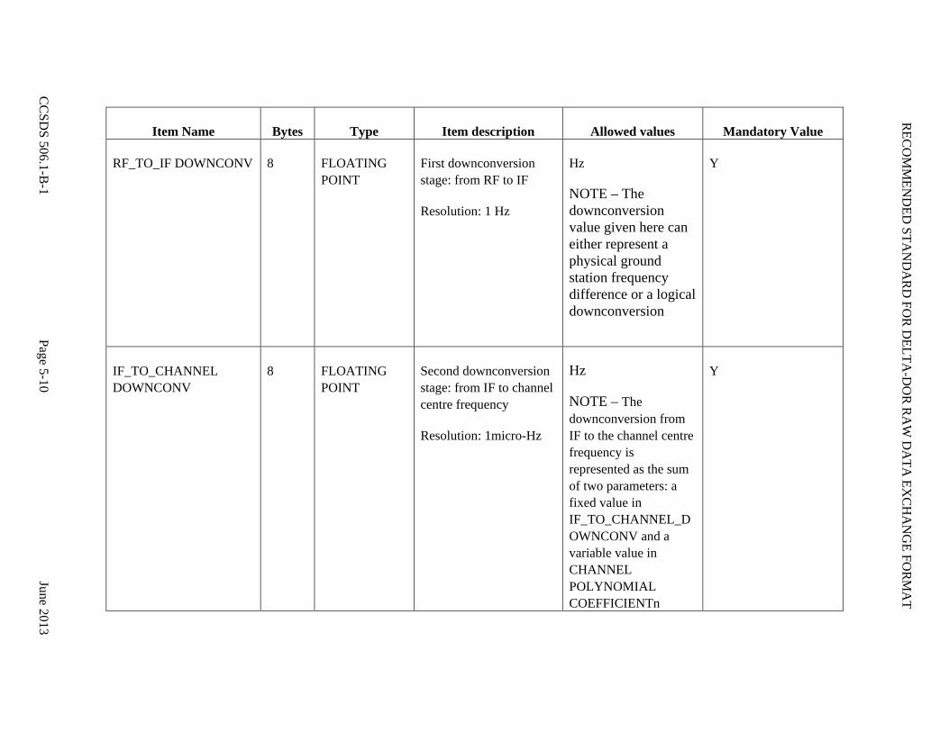
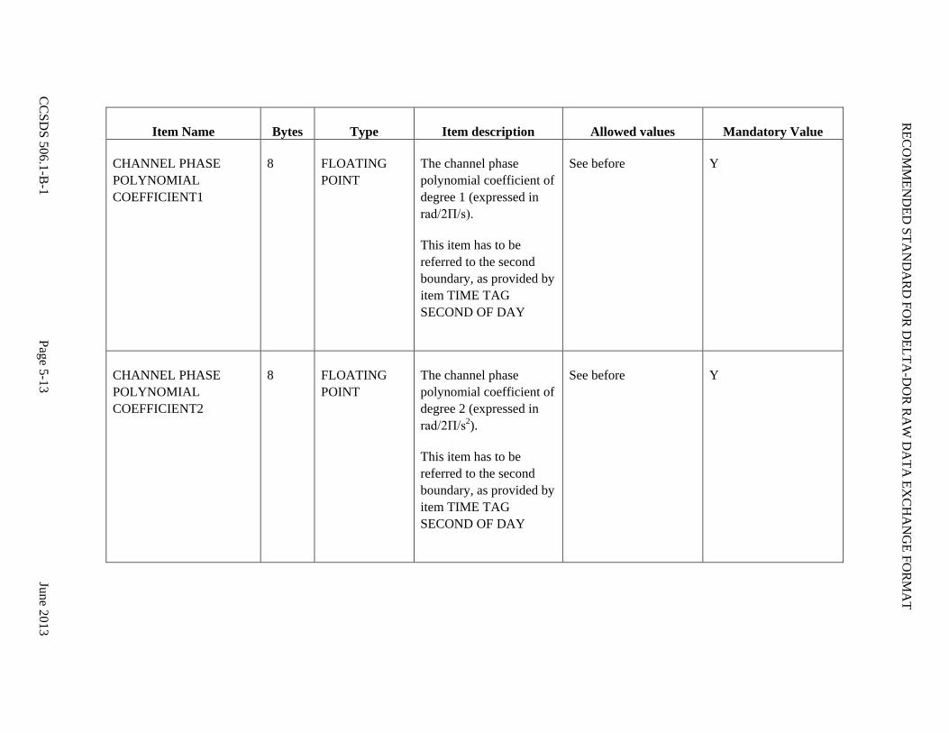
Table 5-1: Product File Header
Item Name Bytes Type Item description Allowed values Mandatory Value
RECORD LABEL 4 CHARACTER ASCII sequence needed to identify data type
‘RDEF’ Y
RECORD LENGTH 4 UNSIGNED INTEGER
Indicates the length, in bytes, of the entire Record
The value shall be equal to 2*(SAMPLE RATE*SAMPLE SIZE)/8 + HEADER SIZE in bytes, where HEADER SIZE = 176 bytes
Y
RECORD VERSION ID 2 UNSIGNED INTEGER
Version number of the data record structure
(=1 for the current version)
The version number shall be synchronised with the one given in the Observation File
Y
STATION ID 2 UNSIGNED INTEGER
Internal network identifier for the station
Integer N
SPACECRAFT ID 2 UNSIGNED INTEGER
Internal network identifier for the spacecraft
Integer N

RECOM
MEN
DED
STAN
DA
RD
FOR D
ELTA-D
OR R
AW
DA
TA EX
CHA
NG
E FORM
AT
CC
SDS 506.1-B
-1 Page 5-9
June 2013
Item Name Bytes Type Item description Allowed values Mandatory Value
SAMPLE SIZE 2 UNSIGNED INTEGER
Specifies the resolution of the data samples contained in this data record
1, 2, 4, 8, 16 Y
SAMPLE RATE 4 UNSIGNED INTEGER
Specifies the sample rate of the data contained in this record, in complex samples per second
SAMPLE RATE * 2 * SAMPLE SIZE shall be a multiple of 32, to keep the sample word length to 32 bits
Y
VALIDITY FLAG 2 UNSIGNED INTEGER
Contains a value to indicate whether an error was detected during recording
The value 0 shall mean no error (or no check was performed)
A positive value is an implementation-dependent error code
Y
AGENCY FLAG 2 UNSIGNED INTEGER
Specifies the Agency creating the file
The value 0 shall mean that this field is not in use. 1= ESA 2 =JAXA 3 = NASA
Y
RECOM
MEN
DED
STAN
DA
RD
FOR D
ELTA-D
OR R
AW
DA
TA EX
CHA
NG
E FORM
AT
CC
SDS 506.1-B
-1 Page 5-10
June 2013
Item Name Bytes Type Item description Allowed values Mandatory Value
RF_TO_IF DOWNCONV 8 FLOATING POINT
First downconversion stage: from RF to IF
Resolution: 1 Hz
Hz
NOTE – The downconversion value given here can either represent a physical ground station frequency difference or a logical downconversion
Y
IF_TO_CHANNEL DOWNCONV
8 FLOATING POINT
Second downconversion stage: from IF to channel centre frequency
Resolution: 1micro-Hz
Hz
NOTE – The downconversion from IF to the channel centre frequency is represented as the sum of two parameters: a fixed value in IF_TO_CHANNEL_DOWNCONV and a variable value in CHANNEL POLYNOMIAL COEFFICIENTn
Y

RECOM
MEN
DED
STAN
DA
RD
FOR D
ELTA-D
OR R
AW
DA
TA EX
CHA
NG
E FORM
AT
CC
SDS 506.1-B
-1 Page 5-11
June 2013
Item Name Bytes Type Item description Allowed values Mandatory Value
TIME TAG YEAR 2 UNSIGNED INTEGER
Specifies the ST year of the data contained in the record
Y
TIME TAG DOY 2 UNSIGNED INTEGER
Specifies the ST DOY of the data contained in the record
1 to 366 Y
TIME TAG SECOND OF DAY
4 UNSIGNED INTEGER
Specifies the ST SOD of the data contained in the record
0 to 86400 Y
TIMETAG PICOSECONDS OF THE SECOND
8 FLOATING POINT
Specifies the ST picoseconds of the second of the first sample contained in the record
A positive non-zero value is used when there is a known delay between the time of the first data sample and the beginning of the second one. Set to 0 if unknown.
Y

RECOM
MEN
DED
STAN
DA
RD
FOR D
ELTA-D
OR R
AW
DA
TA EX
CHA
NG
E FORM
AT
CC
SDS 506.1-B
-1 Page 5-12
June 2013
Item Name Bytes Type Item description Allowed values Mandatory Value
CHANNEL ACCUMULATED PHASE
8 FLOATING POINT
The value of the accumulated whole turns of the channel variable downconverter represented by the phase polynomial coefficients
(Expressed in ‘turns’, i.e., rad/2Π)
This parameter should give the total accumulated phase at the beginning of the frame except the additional channel phase polynomial contribution
Y
CHANNEL PHASE POLYNOMIAL COEFFICIENT0
8 FLOATING POINT
The channel phase polynomial coefficient of degree 0 (expressed in rad/2Π).
This item has to be referred to the second boundary, as provided by item TIME TAG SECOND OF DAY
NOTE – To facilitate data processing the downconverter phase represented by the phase polynomial should be continuous in phase and phase rate from one second to the next
Y
RECOM
MEN
DED
STAN
DA
RD
FOR D
ELTA-D
OR R
AW
DA
TA EX
CHA
NG
E FORM
AT
CC
SDS 506.1-B
-1 Page 5-13
June 2013
Item Name Bytes Type Item description Allowed values Mandatory Value
CHANNEL PHASE POLYNOMIAL COEFFICIENT1
8 FLOATING POINT
The channel phase polynomial coefficient of degree 1 (expressed in rad/2Π/s).
This item has to be referred to the second boundary, as provided by item TIME TAG SECOND OF DAY
See before Y
CHANNEL PHASE POLYNOMIAL COEFFICIENT2
8 FLOATING POINT
The channel phase polynomial coefficient of degree 2 (expressed in rad/2Π/s2).
This item has to be referred to the second boundary, as provided by item TIME TAG SECOND OF DAY
See before Y

RECOM
MEN
DED
STAN
DA
RD
FOR D
ELTA-D
OR R
AW
DA
TA EX
CHA
NG
E FORM
AT
CC
SDS 506.1-B
-1 Page 5-14
June 2013
Item Name Bytes Type Item description Allowed values Mandatory Value
CHANNEL PHASE POLYNOMIAL COEFFICIENT3
8 FLOATING POINT
The channel phase polynomial coefficient of degree 3 (expressed in rad/2Π/s3).
This item has to be referred to the second boundary, as provided by item TIME TAG SECOND OF DAY
See before Y
EMPTY FIELDS (FUTURE EXTENSION)
36 Total number of bytes free to be used for future format extension
Y
EMPTY FIELDS (INTERNAL AGENCY USE)
40 Total number of bytes free to be used by each Agency for its internal purpose
Y
END LABEL 4 INTEGER End label for data synchronization check
Shall be equal to -99999
-99999 Y
RECOMMENDED STANDARD FOR DELTA-DOR RAW DATA EXCHANGE FORMAT
CCSDS 506.1-B-1 Page 5-15 June 2013
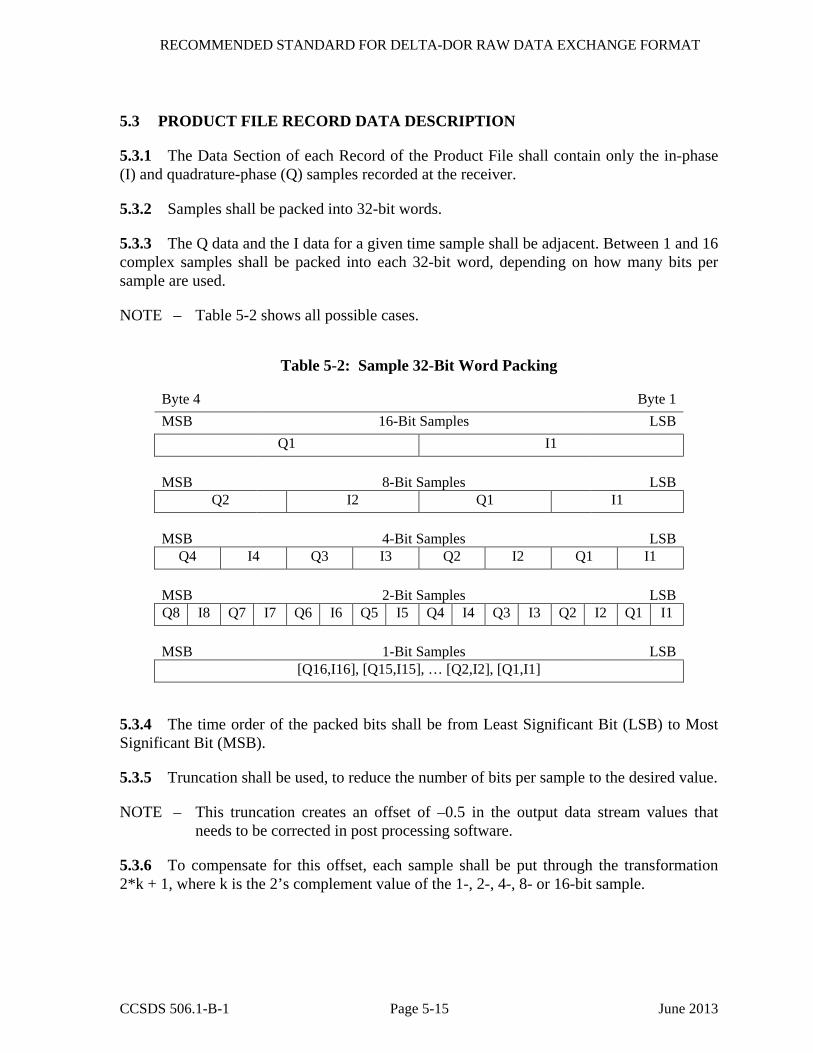
5.3 PRODUCT FILE RECORD DATA DESCRIPTION
5.3.1 The Data Section of each Record of the Product File shall contain only the in-phase (I) and quadrature-phase (Q) samples recorded at the receiver.
5.3.2 Samples shall be packed into 32-bit words.
5.3.3 The Q data and the I data for a given time sample shall be adjacent. Between 1 and 16 complex samples shall be packed into each 32-bit word, depending on how many bits per sample are used.
NOTE – Table 5-2 shows all possible cases.
Table 5-2: Sample 32-Bit Word Packing
Byte 4 Byte 1 MSB 16-Bit Samples LSB
Q1 I1 MSB 8-Bit Samples LSB
Q2 I2 Q1 I1 MSB 4-Bit Samples LSB
Q4 I4 Q3 I3 Q2 I2 Q1 I1 MSB 2-Bit Samples LSB Q8 I8 Q7 I7 Q6 I6 Q5 I5 Q4 I4 Q3 I3 Q2 I2 Q1 I1 MSB 1-Bit Samples LSB
[Q16,I16], [Q15,I15], … [Q2,I2], [Q1,I1]
5.3.4 The time order of the packed bits shall be from Least Significant Bit (LSB) to Most Significant Bit (MSB).
5.3.5 Truncation shall be used, to reduce the number of bits per sample to the desired value.
NOTE – This truncation creates an offset of –0.5 in the output data stream values that needs to be corrected in post processing software.
5.3.6 To compensate for this offset, each sample shall be put through the transformation 2*k + 1, where k is the 2’s complement value of the 1-, 2-, 4-, 8- or 16-bit sample.

RECOMMENDED STANDARD FOR DELTA-DOR RAW DATA EXCHANGE FORMAT
CCSDS 506.1-B-1 Page 5-16 June 2013
NOTES
1 The value zero is not present in this data representation. However, all bits are used and the data are symmetric about zero.
2 A generic description of the Data Section of each Record is given in figure 5-4.

RECOM
MEN
DED
STAN
DA
RD
FOR D
ELTA-D
OR R
AW
DA
TA EX
CHA
NG
E FORM
AT
CC
SDS 506.1-B
-1 Page 5-17
June 2013
BYTE 4 BYTE 3 BYTE 2 BYTE 1
BIT +--+--+--+--+--+--+--+--+--+--+--+--+--+--+--+--+--+--+--+--+--+--+--+--+--+--+--+--+--+--+--+--+ |8 |7 |6 |5 |4 |3 |2 |1 |8 |7 |6 |5 |4 |3 |2 |1 |8 |7 |6 |5 |4 |3 |2 |1 |8 |7 |6 |5 |4 |3 |2 |1 | +--+--+--+--+--+--+--+--+--+--+--+--+--+--+--+--+--+--+--+--+--+--+--+--+--+--+--+--+--+--+--+--+ + SAMPLE WORD 1 + +--+--+--+--+--+--+--+--+--+--+--+--+--+--+--+--+--+--+--+--+--+--+--+--+--+--+--+--+--+--+--+--+ + SAMPLE WORD 2 + +--+--+--+--+--+--+--+--+--+--+--+--+--+--+--+--+--+--+--+--+--+--+--+--+--+--+--+--+--+--+--+--+ ... ... ... ... | | + +
| | +--+--+--+--+--+--+--+--+--+--+--+--+--+--+--+--+--+--+--+--+--+--+--+--+--+--+--+--+--+--+--+--+
|8 |7 |6 |5 |4 |3 |2 |1 |8 |7 |6 |5 |4 |3 |2 |1 |8 |7 |6 |5 |4 |3 |2 |1 |8 |7 |6 |5 |4 |3 |2 |1 | +--+--+--+--+--+--+--+--+--+--+--+--+--+--+--+--+--+--+--+--+--+--+--+--+--+--+--+--+--+--+--+--+
Figure 5-4: General Structure of the Data Section of the Record
RECOMMENDED STANDARD FOR DELTA-DOR RAW DATA EXCHANGE FORMAT
CCSDS 506.1-B-1 Page 6-1 June 2013
6 FILE NAMING CONVENTIONS
6.1 GENERAL
In general, the file name syntax and length should not violate computer constraints for those computing environments in use by Member Agencies for processing Delta-DOR raw data.
NOTE – One observation file is provided per measurement session for each station. A separate Product File is used to contain the data for each scan, for each channel, and for each station. Since this typically results in a large number of files being used for each measurement session, a naming convention is defined to help with managing the Product Files.
6.2 FILE NAMES
6.2.1 The file name shall uniquely define the receiver used to record data, the frequency channel, the spacecraft, the station, the scan, the file type, and the nominal scan start time.
6.2.2 Each file shall be named according to the following convention:
MMMMnNNNtTsSSSSrRRcCC-YYDDDHHMMSS.XXX
where:
a) MMMM is the mission ID (four characters), which shall be the spacecraft ID of the mission requesting the service as defined in the Service Request contained in reference [5].
b) n is a token to indicate that scan identifier follows;
c) NNN is the scan number per session (three-digit integer) starting from 001;
d) t is a token to indicate file type;
e) T is the file type (1 character):
1) I for an Observation File,
2) S for spacecraft scan or Q for quasar scan, for a Product File;
f) s is a token to indicate that station identifier follows;
g) SSSS is the station identifier (four characters), which shall be the same as the receiving station name in the Observation File (4.2.6) for the given station;
h) r is a token to indicate that the receiver identifier follows;
i) RR is the receiver identifier (2 characters);
j) c is a token to indicate that channel identifier follows;

RECOMMENDED STANDARD FOR DELTA-DOR RAW DATA EXCHANGE FORMAT
CCSDS 506.1-B-1 Page 6-2 June 2013
k) CC is the channel identifier (2-digit integer);
l) - is a token to indicate that date follows;
m) YY is the last two digits of the year for nominal scan epoch (2-digit integer);
n) DDD is the day of the year for nominal scan epoch (3-digit integer);
o) HHMMSS is the hour-minute-second for nominal scan epoch (6-digit integer);
p) .XXX is the file extension: .obs for an Observation File, .prd for a Product File.
6.2.3 All character IDs shall be uppercase characters and alphanumeric symbols.
6.2.4 The mission identifier shall refer to the mission that has scheduled the tracking pass.
NOTES
1 It is assumed that each specific tracking pass for each tracking station is scheduled for a specific mission.
2 The object observed during a scan may be the spacecraft that has scheduled the tracking pass, a different spacecraft, or a quasar. The contents of the Observation File (see section 4) must be read to obtain this information.
6.2.5 Special conventions are used for some values in the Observation File name:
a) the observation file channel identifier shall be ‘00’;
b) the observation file scan number shall be ‘000’;
c) the observation file nominal epoch time shall be at or before the nominal epoch for scan 001.

RECOMMENDED STANDARD FOR DELTA-DOR RAW DATA EXCHANGE FORMAT
CCSDS 506.1-B-1 Page A-1 June 2013
ANNEX A
PARAMETERS THAT NEED CONVENTIONS TO BE SPECIFIED
(NORMATIVE)
The parameters included in this annex need to be agreed on whenever an Implementing Arrangement is set up.
This agreement would follow the recommendation contained in annex A of Delta DOR Operations (reference [5]).
Observation File Parameters:
– 4 character Station ID(s) to be used for the Receiving stations;
– 4 character Station ID to be used for the Transmitting station;
– 4 character Source ID for spacecraft, syntax to be agreed in the Implementing Arrangement;
– up to 16 characters Source ID for Quasar, syntax to be agreed in the Implementing Arrangement.
File Name Parameters:
– 4 character Mission ID;
– 4 character Station ID;
– 2 character Channel ID;
– 2 character receiver ID.

RECOMMENDED STANDARD FOR DELTA-DOR RAW DATA EXCHANGE FORMAT
CCSDS 506.1-B-1 Page B-1 June 2013
ANNEX B
SECURITY, SANA, AND PATENT CONSIDERATIONS
(INFORMATIVE)
B1 SECURITY CONSIDERATIONS
B1.1 OVERVIEW
This annex presents the results of an analysis of security considerations applied to the technologies specified in this Recommended Standard.
B1.2 SECURITY CONCERNS RELATED TO THIS RECOMMENDED STANDARD
B1.2.1 Data Privacy
Privacy of data formatted in compliance with the specifications of this Recommended Standard should be assured by the systems and networks on which this Recommended Standard is implemented.
B1.2.2 Data Integrity
Integrity of data formatted in compliance with the specifications of this Recommended Standard should be assured by the systems and networks on which this Recommended Standard is implemented.
B1.2.3 Authentication of Communicating Entities
Authentication of communicating entities involved in the transport of data which complies with the specifications of this Recommended Standard should be provided by the systems and networks on which this Recommended Standard is implemented.
The likelihood of any intentional data corruption involving the RDEF transfer is considered negligible. Moreover, the effects of such corruption will be easily recognizable within the data processing.
B1.2.4 Data Transfer between Communicating Entities
The transfer of data formatted in compliance with this Recommended Standard between communicating entities should be accomplished via secure mechanisms approved by the IT Security functionaries of exchange participants.

RECOMMENDED STANDARD FOR DELTA-DOR RAW DATA EXCHANGE FORMAT
CCSDS 506.1-B-1 Page B-2 June 2013
B1.2.5 Control of Access to Resources
This Recommended Standard assumes that control of access to resources will be managed by the systems upon which provider formatting and recipient processing are performed.
B1.2.6 Auditing of Resources Usage
This Recommended Standard assumes that auditing of resource usage will be handled by the management of systems and networks on which this Recommended Standard is implemented.
B1.3 POTENTIAL THREATS AND ATTACK SCENARIOS
There are no certain threats or attack scenarios that apply specifically to the technologies specified in this Recommended Standard. Potential threats or attack scenarios applicable to the systems and networks on which this Recommended Standard is implemented should be addressed by the management of those systems and networks. Protection from unauthorized access is especially important if the mission utilizes open ground networks such as the Internet to provide ground station connectivity for the exchange of data formatted in compliance with this Recommended Standard.
B1.4 CONSEQUENCES OF NOT APPLYING SECURITY TO THE TECHNOLOGY
There are no known consequences of not applying security to the technologies specified in this Recommended Standard. The consequences of not applying security to the systems and networks on which this Recommended Standard is implemented could include potential loss, corruption, and theft of data.
B1.5 DATA SECURITY IMPLEMENTATION SPECIFICS
Specific information-security interoperability provisions that may apply between agencies involved in an exchange of data formatted in compliance with this Recommended Standard should be specified in the Implementing Arrangement.
B2 SANA CONSIDERATION
The quasar names contained in the Observation File are collected in an ad-hoc SANA registry: http://sanaregistry.org/r/radio_sources/radio_sources.html.
Conventions for Spacecraft and Station IDs may be collected in a future SANA registry.
B3 PATENT CONSIDERATION
At time of publication, the material of this Recommended Standard is not known to be the subject of patent rights.

RECOMMENDED STANDARD FOR DELTA-DOR RAW DATA EXCHANGE FORMAT
CCSDS 506.1-B-1 Page C-1 June 2013
ANNEX C
ABBREVIATIONS AND ACRONYMS
(INFORMATIVE)
ASCII American Standard Code for Information Interchange
CCSDS Consultative Committee for Space Data Systems
Delta-DOR Delta Differential One-Way Ranging
DOR Differential One-Way Ranging
DOY Day Of the Year
GPS Global Positioning System
LSB Least Significant Bit
MSB Most Significant Bit
RDEF Raw Data Exchange Format
SC Spacecraft
SEA Systems Engineering Area
SFTP Secure File Transfer Protocol
SOD Second Of the Day
ST Station Time, as an approximation of UTC as realized at each station receiver
UTC Universal Time Coordinated
VLBI Very Long Baseline Interferometry
RECOMMENDED STANDARD FOR DELTA-DOR RAW DATA EXCHANGE FORMAT
CCSDS 506.1-B-1 Page D-1 June 2013
ANNEX D
INFORMATIVE REFERENCES
(INFORMATIVE)
NOTE – Normative references are provided in 1.6.
[D1] Organization and Processes for the Consultative Committee for Space Data Systems. CCSDS A02.1-Y-3. Yellow Book. Issue 3. Washington, D.C.: CCSDS, July 2011.
[D2] Delta-DOR Technical Characteristics and Performance. Report Concerning Space Data System Standards, CCSDS 500.1-G-0. Proposed Green Book.
[D3] Navigation Data—Definitions and Conventions. Report Concerning Space Data System Standards, CCSDS 500.0-G-3. Green Book. Issue 3. Washington, D.C.: CCSDS, May 2010.
[D4] The Application of CCSDS Protocols to Secure Systems. Report Concerning Space Data System Standards, CCSDS 350.0-G-2. Green Book. Issue 2. Washington, D.C.: CCSDS, January 2006.
[D5] Catherine L. Thornton and James S. Border. Radiometric Tracking Techniques for Deep-Space Navigation. JPL Deep-Space Communications and Navigation Series. Joseph H. Yuen, Series Editor. Hoboken, N.J.: Wiley, 2003.
[D6] Theodore D. Moyer. Formulation for Observed and Computed Values of Deep Space Network Data Types for Navigation. JPL Deep-Space Communications and Navigation Series. Joseph H. Yuen, Series Editor. Hoboken, N.J.: Wiley, 2003.
[D7] Delta Differential One-way Ranging. Module 210 in DSN Telecommunications Link Design Handbook. DSN No. 810-005, Rev. E. Pasadena California: JPL, April 8, 2013.
[D8] Timothy McElrath, et al. “Mars Exploration Rovers Orbit Determination Filter Strategy.” In AIAA/AAS Astrodynamics Specialist Conference and Exhibit, August 16-19, 2004 (Providence, Rhode Island). Pasadena, CA: JPL, 2004.
[D9] Radio Frequency and Modulation Systems—Part 1: Earth Stations and Spacecraft. Recommendation for Space Data System Standards, CCSDS 401.0-B-21. Blue Book. Issue 21. Washington, D.C.: CCSDS, July 2011.
[D10] Orbit Data Messages. Recommendation for Space Data System Standards, CCSDS 502.0-B-2. Blue Book. Issue 2. Washington, D.C.: CCSDS, November 2009.
[D11] Tracking Data Message. Recommendation for Space Data System Standards, CCSDS 503.0-B-1. Blue Book. Issue 1. Washington, D.C.: CCSDS, November 2007.
[D12] X-Band Radio Source Catalog. Module 107B in DSN Telecommunications Link Design Handbook. DSN No. 810-005, Rev. E. Pasadena California: JPL, April 8, 2013.

RECOM
MEN
DED
STAN
DA
RD
FOR D
ELTA-D
OR R
AW
DA
TA EX
CHA
NG
E FORM
AT
CC
SDS 506.1-B
-1 Page E-1
June 2013
ANNEX E
EXAMPLE OF RDEF OBSERVATION FILE
(INFORMATIVE)
File Name: M01On000tIsDS24r02c00-08001170000.obs
# Observation File V VERSION = 1 # Comments # # # # # R STATION = DS24 T STATION = DS25 Z
Observation Header
# # SCAN_NUM SRC_ID START_TIME STOP_TIME RA DEC TFREQ # ------------------------------------------------------------------------------------------ S 001 CTD_26 2008-001T17:00:00 2008-001T17:04:00 60.797422 26.005385 0.0000 # # DATAFILE COH_FLAG DOR_MULT FSUB HARMONIC # ------------------------------------------------------------------------------------------ D M01On001tQsDS24r02c01-08001170000.prd T 0 375000.0 0 D M01On001tQsDS24r02c02-08001170000.prd T 1/440 375000.0 1 D M01On001tQsDS24r02c03-08001170000.prd T 1/440 375000.0 -2 D M01On001tQsDS24r02c04-08001170000.prd T 1/440 375000.0 2 Z
Scan Section # 1
# # SCAN_NUM SRC_ID START_TIME STOP_TIME RA DEC TFREQ # ------------------------------------------------------------------------------------------ S 002 M01O 2008-001T17:06:00 2008-001T17:10:00 69.849538 22.975839 8403456000.0000 # # DATAFILE COH_FLAG DOR_MULT FSUB HARMONIC # ------------------------------------------------------------------------------------------ D M01On002tSsDS24r02c01-08001170600.prd T 0 375000.0 0 D M01On002tSsDS24r02c02-08001170600.prd T 1/440 375000.0 1 D M01On002tSsDS24r02c03-08001170600.prd T 1/440 375000.0 -2 D M01On002tSsDS24r02c04-08001170600.prd T 1/440 375000.0 2 Z
Scan Section # 2
# # SCAN_NUM SRC_ID START_TIME STOP_TIME RA DEC TFREQ # ------------------------------------------------------------------------------------------- S 003 P_0507+17 2008-001T17:12:00 2008-001T17:16:00 77.533972 18.013694 0.0000 # # DATAFILE COH_FLAG DOR_MULT FSUB HARMONIC # ------------------------------------------------------------------------------------------- D M01On003tQsDS24r02c01-08001171200.prd T 0 375000.0 0 D M01On003tQsDS24r02c02-08001171200.prd T 1/440 375000.0 1 D M01On003tQsDS24r02c03-08001171200.prd T 1/440 375000.0 -2 D M01On003tQsDS24r02c04-08001171200.prd T 1/440 375000.0 2 Z
Scan Section # 3
F LOGfile <filename> E *=END=*
Ending Section