Decentralized servo architecture webinar
22
1
Transcript of Decentralized servo architecture webinar

1

Agenda
• Architecture options
• Sitara AM64x for motion control
• Fast Serial Interface (FSI)
• C2000 real-time microcontrollers for motor control
• Get started

Architecture

Centralized and decentralized multi-axis servo control
Decentralized• Control loop processing
distributed across system
• Isolated communication
between control boards
• Simplified motion control
board
Centralized• Control loop processing all in
one location
• Isolated actuation/feedback
signals
• Simplified power stage
boards

Where and why to use decentralized control
Where?• Multi-axis robotics
• Linear transport systems
• CNC machines
• Autonomous Guided Vehicles
Why?• More intelligence at the motor drive
• No external control cabinet needed
• Reduced system cabling costs
• Improved control loop performance

AM64x
F28002/4x LaunchPad(s) +
Power Stage Boosterpack
Example AM64x + F28002/4x decentralized architecture
ARMCortex A53
ARM
Cortex A53
(Motion)
C28x
(Current/
FOC)
M
Encoder
C28x
(Current/
FOC)
M
Encoder
FSI
C28x
(Current/
FOC)
M
Encoder
FSI
FSI
ARM
Cortex R5F
(Position/
Speed)
ARM
Cortex R5F
(Position/
Speed)
ARM
Cortex R5F
(Position/
Speed)
ARM
Cortex R5F
(Position/
Speed)
ReinforcedIsolationBoundary
Multi-protocol Industrial Ethernet
Integrated Motion Control
Centralized Multi-axis
Position/SpeedControl
Fast, low-pin count
communication
Distributed Current/FOC
Control

Demo
https://training.ti.com/decentralized-multi-axis-motor-control
Sitara™ AM64x processors:
Outer control loops with CiA402 drive profile run on a Sitara™
AM64x processor using EtherCAT® communication from a
PC
Adapter boards: Real-time, low pin-count, robust communication
up to 200 Mbps over Fast Serial Interface (FSI) adapter boards
C2000™ real-time controllers:
Inner current loops run on F2800x LaunchPad™ development kits
BoosterPack™ development
kits: GaN three-phase inverter BoosterPack™ development kits

Sitara AM64x Processors

AM64x• Cores & Memory
– Dual Cortex-A53 up to 1GHz
– Quad Cortex-R5F up to 800MHz
– 2MB on-chip SRAMECC on all critical memories
– 16b LPDDR4/DDR4 controller with inline ECC
• Industry 4.0 Services– Dual-core Arm Cortex-A53 cores capable of running RT Linux
enable high-level applications and networking
• Multi-axis Control– Up to 4x Arm Cortex-R5F cores running at 800MHz provide more
than 5,000 DMIPs of processing for real-time control tasks
• Fast Serial Interface– FSI allows fast, serial communication across isolation boundaries
with multiple C2000 devices
• Multiprotocol Industrial Communications– PRU-ICSS(Gb) subsystem integrates EtherCAT, PROFINET,
EtherNet/IP capability into a single package
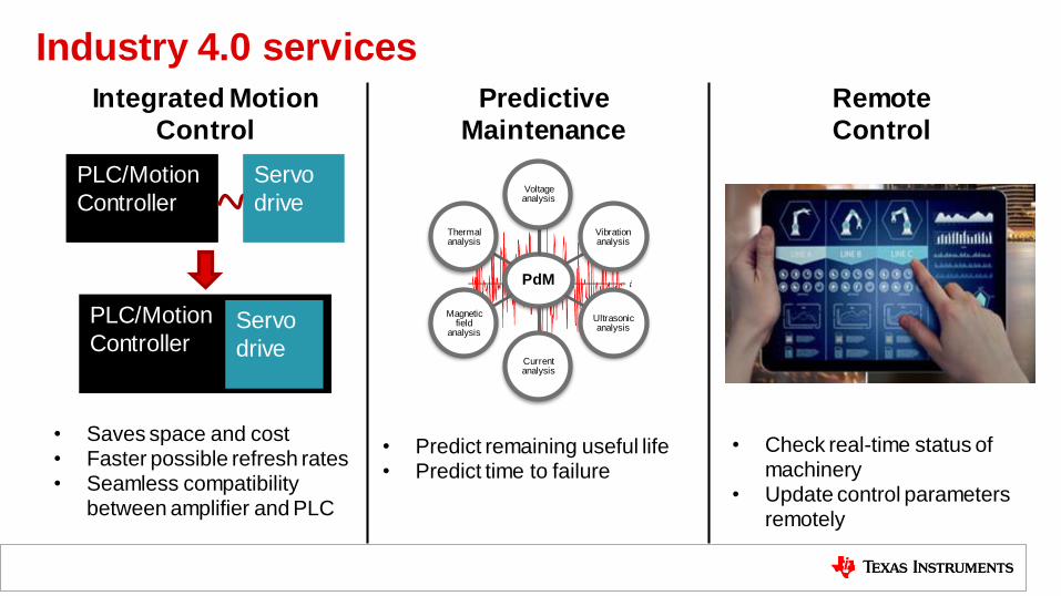
Industry 4.0 services
PLC/Motion
Controller
Servo
drive
PLC/Motion
ControllerServo
drive
• Saves space and cost• Faster possible refresh rates• Seamless compatibility
between amplifier and PLC
Integrated Motion
Control
PdM
Voltage analysis
Vibration analysis
Ultrasonic analysis
Current analysis
Magnetic field
analysis
Thermal analysis
Predictive
Maintenance
• Predict remaining useful life• Predict time to failure
Remote
Control
• Check real-time status of machinery
• Update control parameters remotely

Multi-axis, real-time control
• Arm Cortex-R5F cores running at 800MHz provides
greater than 5,000 DMIPs of processing power
– Allows for tighter control loops, more advanced algorithms, and more background processing
• Tightly-coupled memory (TCM) for each core to allow
deterministic, single-cycle access for instruction and data
– Guarantees real-time deadlines are met on each iteration of the loop
• Up to 4x Arm Cortex-R5F cores provides software partitioning
options
– Pipelined approach: each core handles a specific function for all axes and then passes the result to the next stage in the pipeline
– Distributed approach: each core handles all control code for one or more axes
• Software Development Kit provided including Real-time
operating system (RTOS) and control libraries
– Decrease getting started and overall development time

Sitara improves the overall development process and supply chain
by:
1. Enabling re-allocation of inventory from one protocol to another in minutes to meet sudden demand changes
2. Narrowing down hardware procurement to a single vendor
3. Drastically reducing inventory management complexity
4. Providing a single hardware design to meet the needs of multiple markets
Multiprotocol industrial Ethernet
ProfinetIRT/RT
SKU
EtherNet/IP
SKU
EtherCAT
SKU
ProfinetIRT/RT module
EtherNet/IP module
EtherCATmodule
InventoryCommunication
module
ProfinetIRT/RT ASIC
EtherNet/IP ASIC
EtherCAT
ASIC
Communication
device
The typical multi-protocol design process has many
disadvantages including:
1. Complex inventory management and accurate forecasting needed for each individual protocol
2. Multiple silicon suppliers required
3. Separate hardware designs for each protocol
4. Expensive total cost when using multiple ASICs
Traditional flow
ProfinetIRT/RT
SKU
EtherNet/IP SKU
EtherCATSKU
Multi-protocol board
InventoryCommunication
module
Sitara™ processors
Communication
device
Flow with Sitara

FSI
Very Low Signal Count
Standard LVCMOS IO
Buffer
Low Latency & up to ~200 Mbps BW
FSIStandard SPI
SERDES/LVDS
RapidIO
PCIe
I2C
SD I/O
QuadSPI
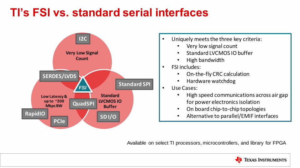
• Uniquely meets the three key criteria:• Very low signal count• Standard LVCMOS IO buffer• High bandwidth
• FSI includes: • On-the-fly CRC calculation• Hardware watchdog
• Use Cases:• High speed communications across air gap
for power electronics isolation • On board chip-to-chip topologies• Alternative to parallel/EMIF interfaces
TI’s FSI vs. standard serial interfaces
Available on select TI processors, microcontrollers, and library for FPGA

Enabling new options for drive architecturesFast Serial Interface (FSI) enables high speed (200 Mbps/3-wire or 100 Mbps/2-wire) chip-
to-chip communications while leveraging the latest in TI’s galvanic isolation technology.
Benefits
• Reduces need for isolation components
• Enables real time loops to span air gap
• Enables new drive architectures
• Smart sensing/Data concentrator
• Smart sensor/resolver/position sensor
• Host/Slave controller
• Loop controller – actuation/sensing
• Alternative to mixed signal ASIC/FPGA
Features
• Fast transfer (100-200Mbit/sec @50MHz CLK)
• Line break detect
• Ping frame: periodic frame for line break detect
• Frame watchdog on receiver
• HW CRC- polynomial calculation and checker
• Signal line skew compensation
• Customizable tags and data
• Flexible topologies: point-to-point, star, daisy-chain

C2000 real-time microcontrollers

PWM Customization
PWM Protection
Industrial
Communications
UART
CAN
USB
I2C
Ethernet
More …
Position Sensor Interface
Pulse Train Output / Input
Actuation
PWM
three-
phase
inv erter
PMmotor
Position
sensor
SDFilters
ADC
PWM
Trip
Fluxgatesensor s
D S isolated ADCs
eQEP
ADC
DAC
Isolatedshunt current
buffer
Drive
Control
SOC
Isolatedgate dr ive
Sensing
Protection
LineInterface
Processing
DAC
150 ps resolution
Deadband Gen
Autonomous ADC Trig
>60x8 Trip XBAR
Protection
50 ns to PWM trip
Up to 16-bit, 4 MSPS
Up to 12-bit, 12 MSPS
Digital Post Process
High Precision
Up to 8 Channels, with
compare
Digital and Analog
Position Sensor Interface
EnDat, BISS, t-format,
HDSL, SSI
Resolver, SIN/COS
C28x™
Core(s)
CLA
Core(s)
FlashRAMROM
RA
M
RAM ROM
0
ws
0
ws
0
ws
0
ws
Wide
access
0ws 0ws
• Deterministic pre-fetch
• Zero wait-state linear code
• High determinism
• Fast interrupt response
• Atomic ALU
• Linear memory space
• Zero wait-state RAM, ROM
• Shared RAM between cores
Integrated innovation: www.ti.com/c2000drivesLowest latency, highest precision, minimum jitter
EMIFMemory
Sitara™
DZ Security Trig AcceleratorFloating Point
Configurable Logic
Block
SPI
FSI
secondary
controller
< 500 ns calculation for FOC control loop
Functional SafetySIL-2 Random
Hardware Component
Use in SIL-3 systems
TUV certifications and
servo drive concept
reports available

Get started

Getting started
FSI documentation• See Device TRMs ex: TMS320F28002x Technical Reference Manual• Using the Fast Serial Interface (FSI) With Multiple Devices in an Application• Fast Serial Interface (FSI) Skew Compensation
Evaluation modules• TMDSFSIADAPEVM• LAUNCHXL-F280049C• LAUNCHXL-F280025C• BOOSTXL-3PHGANINV• TMDS64GPEVM
Reference designs• TIDM-02006 (C2000 F2838x outer loop controller –FSI – F28004x/2x nodes) • AM64x Software Development Kit with FSI based Decentralized Servo example• AM64x + C2000 decentralized servo demo

Q&A

SLYP744

IMPORTANT NOTICE AND DISCLAIMERTI PROVIDES TECHNICAL AND RELIABILITY DATA (INCLUDING DATASHEETS), DESIGN RESOURCES (INCLUDING REFERENCEDESIGNS), APPLICATION OR OTHER DESIGN ADVICE, WEB TOOLS, SAFETY INFORMATION, AND OTHER RESOURCES “AS IS”AND WITH ALL FAULTS, AND DISCLAIMS ALL WARRANTIES, EXPRESS AND IMPLIED, INCLUDING WITHOUT LIMITATION ANYIMPLIED WARRANTIES OF MERCHANTABILITY, FITNESS FOR A PARTICULAR PURPOSE OR NON-INFRINGEMENT OF THIRDPARTY INTELLECTUAL PROPERTY RIGHTS.These resources are intended for skilled developers designing with TI products. You are solely responsible for (1) selecting the appropriateTI products for your application, (2) designing, validating and testing your application, and (3) ensuring your application meets applicablestandards, and any other safety, security, or other requirements. These resources are subject to change without notice. TI grants youpermission to use these resources only for development of an application that uses the TI products described in the resource. Otherreproduction and display of these resources is prohibited. No license is granted to any other TI intellectual property right or to any third partyintellectual property right. TI disclaims responsibility for, and you will fully indemnify TI and its representatives against, any claims, damages,costs, losses, and liabilities arising out of your use of these resources.TI’s products are provided subject to TI’s Terms of Sale (https:www.ti.com/legal/termsofsale.html) or other applicable terms available eitheron ti.com or provided in conjunction with such TI products. TI’s provision of these resources does not expand or otherwise alter TI’sapplicable warranties or warranty disclaimers for TI products.IMPORTANT NOTICE
Mailing Address: Texas Instruments, Post Office Box 655303, Dallas, Texas 75265Copyright © 2021, Texas Instruments Incorporated