DAMAGE TOLERANCE AND REPAIR OF UD-RIBS … · of lattice composite fuselage structure are ... of...
10
Abstract The results of the investigation of influence of delamination in UD ribs on strength parameters of lattice composite fuselage structure are presented. The dependences of strength parameters of the lattice structure on parameters of repaired structure fragment have been obtained. The results of evaluation of strength and weight of repaired lattice structure are presented. 1 General Introduction Investigations of lattice composite airframes, which were carried out in frames of Russian project “CM Fuselage” and European FP7 project “ALaSCA” (Advanced lattice structures for composite airframes, [1]), have demonstrated high potential of these structures in weight saving of civil aircraft fuselage structures. Coincidence of a direction of force flows with a direction of fibres in load-bearing ribs (UD-ribs) has allowed to realize effectively high strength properties of composite materials in frames of lattice fuselage section structure with two skins (Figure 1). Experimental investigations showed that composite ribs of lattice structure are more sensitive to impacts than elements of structures with conventional layout. It does not allow to meet durability requirements without development of protection system for UD-ribs. Figure 1 Concept of lattice structure of composite fuselage section Topology of the lattice structures enable developing effective protection of UD-ribs against impacts and environment. The concept of “full” protection has been developed in frames of the FP7 “PoLaRBEAR” project (Production and Analysis Evolution for Lattice Related Barrel Elements under Operations with Advanced Reliability, [2]). This concept of protection (Figure 2) provides undamageability of UD-ribs after certified impact during long-term service, but the protection system turned out to have quite high weight parameters. Use of this protection system did not allow to get weight benefit more than 5-10 % for the lattice fuselage section in comparison with metal analogue. Investigations, carried out in TsAGI, showed redundancy of "full" protection, especially taking into account high survivability property of the lattice structure. The more effective concept of protection regarding weight saving is proposed in this work. The concept is based on allowing occurrence of safe damages in the lattice ribs after the certificated impact during long-term service. DAMAGE TOLERANCE AND REPAIR OF UD-RIBS OF LATTICE COMPOSITE FUSELAGE STRUCTURES Evgeny Dubovikov, Victor Fomin, Maria Glebova Central Aerohydrodynamic Institute (TsAGI) Key words: lattice composite structure, damage, repair 1
Transcript of DAMAGE TOLERANCE AND REPAIR OF UD-RIBS … · of lattice composite fuselage structure are ... of...

Abstract The results of the investigation of influence of delamination in UD ribs on strength parameters of lattice composite fuselage structure are presented.
The dependences of strength parameters of the lattice structure on parameters of repaired structure fragment have been obtained. The results of evaluation of strength and weight of repaired lattice structure are presented.
1 General Introduction Investigations of lattice composite airframes, which were carried out in frames of Russian project “CM Fuselage” and European FP7 project “ALaSCA” (Advanced lattice structures for composite airframes, [1]), have demonstrated high potential of these structures in weight saving of civil aircraft fuselage structures. Coincidence of a direction of force flows with a direction of fibres in load-bearing ribs (UD-ribs) has allowed to realize effectively high strength properties of composite materials in frames of lattice fuselage section structure with two skins (Figure 1).
Experimental investigations showed that composite ribs of lattice structure are more sensitive to impacts than elements of structures with conventional layout. It does not allow to meet durability requirements without development of protection system for UD-ribs.
Figure 1 Concept of lattice structure of
composite fuselage section Topology of the lattice structures enable
developing effective protection of UD-ribs against impacts and environment. The concept of “full” protection has been developed in frames of the FP7 “PoLaRBEAR” project (Production and Analysis Evolution for Lattice Related Barrel Elements under Operations with Advanced Reliability, [2]). This concept of protection (Figure 2) provides undamageability of UD-ribs after certified impact during long-term service, but the protection system turned out to have quite high weight parameters. Use of this protection system did not allow to get weight benefit more than 5-10 % for the lattice fuselage section in comparison with metal analogue.
Investigations, carried out in TsAGI, showed redundancy of "full" protection, especially taking into account high survivability property of the lattice structure. The more effective concept of protection regarding weight saving is proposed in this work. The concept is based on allowing occurrence of safe damages in the lattice ribs after the certificated impact during long-term service.
DAMAGE TOLERANCE AND REPAIR OF UD-RIBS OF LATTICE COMPOSITE FUSELAGE STRUCTURES
Evgeny Dubovikov, Victor Fomin, Maria Glebova
Central Aerohydrodynamic Institute (TsAGI)
Key words: lattice composite structure, damage, repair
1

EVGENY DUBOVIKOV, VICTOR FOMIN, MARIA GLEBOVA
Figure 2 Concept of multilevel system of
protection Influence of the damages in UD-ribs on
strength properties of the lattice section structure was investigated in order to determine rational parameters of the protection system, which allows occurrence of damages which do not lead to reducing of residual strength at long time service lower than the required level. The results of the investigation of influence of geometrical parameters of damages (longitudinal delamination) in UD ribs on strength parameters of lattice composite fuselage structure are presented in the work.
It should be noted that “safe” damage can grow during the structure service, e.g. micro crack can grow due to influence of moisture and temperature (especially with freezing of the water); short delamination can propagate through the UD-rib due to local buckling of delaminated part, etc. Therefore, to provide safe exploitation of the structure, the effective repair methods are required. The methods must provide complete restoration of initial stiffness and strength characteristics of the structure.
Two variants of repair of the lattice fuselage structure with damaged UD-rib have been analyzed: bonded and bolted repairs. The dependences of strength parameters of the lattice section structure on the parameters of repaired fragment were obtained by means of numerical investigations. The results of evaluation of strength and weight of repaired lattice structure are presented.
2 Influence of damages on strength of lattice composite fuselage structure Assurance of sufficient level of residual strength for the structure with damaged elements is the necessary requirement to the structure designing, which is connected with satisfaction of conditions of long-term strength. In the documents regulating airworthiness rules [6], the damages are divided into categories in accordance with their severity level. For each category of the damage it is recommended to provide certain level of strength at the structure designing (Figure 3 – on the basis of fig. 7.2.1.a from [7]).
Figure 3 Dependence of designed strength on
damage level The most critical kind of damage/defect in
the lattice structure - longitudinal delamination of UD-rib was investigated in the given work. Barely visible damages (BVID), and also those damages which cannot be detected by nonexperts during the period between two scheduled inspections, can increase in sizes and propagate through the rib. Decrease in effective rigidity of the damaged rib leads to occurrence of additional strain concentration in the ribs located around the damaged rib. It, in turn, leads to decreasing load-bearing capability of the section structure (Figure 4).
2

DAMAGE TOLERANCE AND REPAIR OF UD-RIBS OF LATTICE COMPOSITE FUSELAGE STRUCTURES
Figure 4 Degradation of section structure
strength owing to initial delamination in rib The strength analysis of the section
structure in frames of sizing or optimization, as a rule, is carried out with use of results of linear calculation of stress-strain state. Thus, it is necessary to perform preliminary researches to meet the requirement on long-term strength of the section structure. The researches include solving the following tasks:
1) Nonlinear analysis of lowering effective stiffness of the rib with initial delamination at compression;
2) Quasilinear FEM analysis of deformations for the lattice section structure with “weakened” ribs;
3) Calculation of reduction factors for parameters of ribs strength criteria for using in linear strength analysis of lattice section structure;
4) Analysis of residual strength of the lattice section structure with damaged ribs.
2.1 Reduction of effective stiffness of lattice rib with initial delamination at compression The algorithm of the approximate analysis of decrease of strength properties of lattice ribs with the initial delamination has been developed in frames of the project FP7 PoLaRBEAR [3]. The analysis was based on the energy approach. In the given work, the similar approach was used to develop the technique of the automated numerical estimation of effective stiffness reduction for such ribs in frames of multilevel algorithm for designing of pro-composite airframes. This technique was based on the analysis of the nonlinear deforming process and propagation of delamination with use of analytical models of the lattice ribs with initial
delamination. The energy approach was used to solve the problem of behaviour of the damaged rib at compression. In the given task, the approach consisted in determination of potential energy of deformation and in calculation of work on the delamination propagation for any possible state of the rib with the subsequent choice of the state characterized by the least total energy ().
Figure 5 Possible states of lattice rib with initial
delamination
Figure 6 Energy of rib at different states Since the energy spent for the process of
propagation of delamination constitutes a small part (<3 %) of the potential energy of deformation, this process was approximately considered as separation of one layer from another as a result of the destruction of the binder layer located between these load-bearing layers at a transverse stretching. Besides mechanics of the destruction and the analysis of local concentration of deformations in the crack tip were not investigated.
Potential energy of deformation was determined with use of nonlinear analytical
3

EVGENY DUBOVIKOV, VICTOR FOMIN, MARIA GLEBOVA
solution for the post-buckling deformations of delaminated part of the rib up to its destruction. The deflection w of this part of the rib (length ℓ) was approximated by use the function
x2sinfw π= ,
where f is amplitude of deflection. The longitudinal force Pℓ in delaminated part of the rib (relative shortening deformation rε of the rib) was defined by the formula
~h~2])h~1(2[P~2P])h~1(2[P
cr
cr0cr+−−
+−−=
ε
ε.
Here crcr P,ε are the critical deformation and
the critical force at buckling of delaminated part of the rib; L/~,H/hh~ == .
The validation researches performed by
means of precise method with use of the nonlinear FEM module of the program NASTRAN, have shown satisfactory accuracy of the approximate solutions (error < 5 %).
As the length of the delamination and its location in the rib can be any, all possible values of the initial delamination parameters have to be analyzed. Parametrical calculations were carried out with a choice of the most adverse variant for strength properties of the structure. The result of this analysis is the value (ϕr) of degradation of stiffness characteristics of the rib with initial delamination at compression, which corresponds to relative shortening εr=−∆x/L. The reduction factor ϕr is calculated by means of comparison of the force P0, which is sustained by the rib without damages at the preset value (εr) of relative shortening , with the force P for the rib with delamination at the same shortening (Figure 7), i.e. ϕr = P/ P0.
The force P which the rib sustains, depends on the post-buckling state of the delaminated part. When the maximum deformation εmax in the delaminated part exceeds the value εuc of the maximal allowed deformation of compression for the UD-rib's material, this part of the rib is considered as destroyed (Figure 8). The maximum deformation in the delaminated part is calculated by the formula:
1P/Ph22Pa crmax 11 −−=
πε .
Figure 7 Force in damaged rib at compression
Figure 8 Maximal strains and stiffness reduction
factors at compression of delaminated rib The factors ϕr are used for imitation of
effective stiffness parametres of the ribs with delamination in numerical FE model of the lattice section for the quasilinear analysis of residual strength.
2.2 Strength degradation of lattice section with delaminated ribs The approach developed in frames of the project FP7 PoLaRBEAR for strength analysis [4] was used for estimation of strength properties of the lattice section structure. In the given work, this approach was realized in the form of algorithm of analysis of residual strength for lattice structure of composite fuselage section containing ribs with delamination.
The analysis of strength degradation of lattice structure includes the following operations:
4

DAMAGE TOLERANCE AND REPAIR OF UD-RIBS OF LATTICE COMPOSITE FUSELAGE STRUCTURES
− Determination of the linear stress-strain state (I) of the structure without damages,
− Calculation of reduction factors for stiffness characteristics of in advance appointed ribs with initial delamination on the basis of longitudinal deformations of compression of these ribs,
− Determination of the linear stress-strain state (II) of the structure with damaged ribs,
− Comparison of the states (I) and (II) with the analysis of additional concentration of deformations,
− Calculation of the maximum relative change of the deformation concentrations, which defines the strength parameters of the lattice structure. The stress-strain states (I) and (II) are
defined on the basis of finite-element model of the section structure with use of so-called "box" model of lattice ribs [5] (Figure 9). The factor defining the increase of concentration of deformations in the damaged structure, is calculated by the formula
maxmax /k εεε∗= .
For reduction of the parameters corresponding to the maximum allowed deformations of compression uc
rε in the strength criteria (Figure 10), the factor ur is used:
εk/1ru = .
Figure 9 Additional concentration of strains
because of rib with “weakened” rib
Figure 10 Example of strength lowering for
lattice section with “weakened” rib The calculation results show that the
degradation of lattice section strength parameters approaches 25 % depending on parameters of damages (delamination) in ribs.
The created method of estimation of strength degradation for the lattice section with delaminated ribs is applied to defining the reduced parameters of the deformation strength criteria. These criteria are used as constraints for deformations of UD-ribs at the sizing of the lattice section structure basing on the linear FEM analysis.
3 Repair of UD-ribs of lattice composite fuselage structure
3.1 Basic requirements for repair methods Providing the sufficient residual strength of the damaged structure is the necessary condition to provide sufficient long-term strength of the structure. In the documents regulating the airworthiness rules [6], the damages are divided into 5 categories:
no. Kind of
damage Detection Residual strength
I BVID - ≥UL II Visible by
experts Schedule inspection ≥UL
III Visible by non-experts
During few flights ≥LL
IV Known (discrete source)
After flight
≥LL (restricted maneuver)
5
EVGENY DUBOVIKOV, VICTOR FOMIN, MARIA GLEBOVA
V Non-certified
After flight
≥LL (strongly restricted maneuver)
The proposed concept of “uncomplete”
protection of UD-ribs provides undamageability of the lattice skeleton after impacts with low energy levels. After such impact, the elastic skins only can be damaged (I and II damage categories) without occurrence of the through-thickness crack leading to depressurization of the passenger cabin.
After certified impacts with higher energy levels UD-ribs can be damaged (I and II damage categories). The residual strength of the structure should be not lower than limit loads level.
However, as it has been noted above, the damages of these categories can grow at the structure service. It can lead to decrease of the section structure strength.
Presence of the damage in the lattice section structure is possible not only because of impact in service, but also because of occurrence of defect at the manufacture stage, for example, as a result of defective adhesion bond.
As the damages and the defects can lead to the strength decrease at long-term operation, corresponding concepts of repair have been developed for lattice structures of composite fuselage section.
For repair of skins, it is recommended to use the conventional methods of repair, which are widely applied to the structures «Black metal». As to repair of the damaged elements of load-bearing lattice skeleton, owing to features of topology of the skeleton layout and structure of UD-ribs, the development of effective repair methods on a basis of bolted and-or glue connections is necessary. It is necessary to notice that, according to the requirements [8] to designing of lattice fuselage sections, bolted-type repair is accepted for the lattice structures as the core. Other methods of repair should be proved by the experimental researches including modelling of all features of long-term operation of airframes. Besides, any repair should be made in short terms and with use of accessible materials, with the minimum damage of adjoining structures.
For numerical substantiation of a repair method it is necessary to show that the repair method restores the structure to the condition of the airworthiness [6], that is, the repair restores load-bearing capability of the structure to the level of 100 % of UL loads, and also it restores completely the stiffness characteristics of the structure.
The basic requirements to the repair method: − restoration of initial strength and stiffness
characteristics of the structure, − the repaired structure must sustain UL loads
after all life cycle, − additional inspection requirements should
not be shown to the repair product .
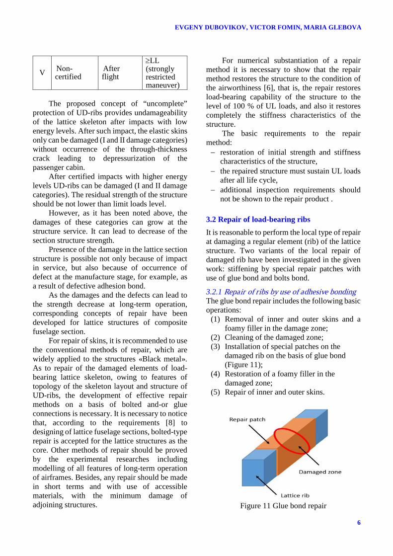
3.2 Repair of load-bearing ribs It is reasonable to perform the local type of repair at damaging a regular element (rib) of the lattice structure. Two variants of the local repair of damaged rib have been investigated in the given work: stiffening by special repair patches with use of glue bond and bolts bond.
3.2.1 Repair of ribs by use of adhesive bonding The glue bond repair includes the following basic operations:
(1) Removal of inner and outer skins and a foamy filler in the damage zone;
(2) Cleaning of the damaged zone; (3) Installation of special patches on the
damaged rib on the basis of glue bond (Figure 11);
(4) Restoration of a foamy filler in the damaged zone;
(5) Repair of inner and outer skins.
Figure 11 Glue bond repair
6

DAMAGE TOLERANCE AND REPAIR OF UD-RIBS OF LATTICE COMPOSITE FUSELAGE STRUCTURES
The analysis of the glue bond repair, which
is traditionally applied to repair of skins, has shown that this kind of repair has restrictions on application to lattice ribs. It is conditioned by rather low strength characteristics of modern glues.
Numerical researches of dependence of the minimum length of the glue connection for the repair patch on the area of the rib cross-section for various values of strength characteristics of glues (Figure 12) have shown that in the case of the lattice section structure with rational parameters (the zone noted by red circle in the diagram) the glue must have the shear strength not less than 7-9 kg/mm2. Taking into consideration that strength of modern glues does not exceed 5 kg/mm2, it is possible to conclude that the glue bond repair of ribs does not allow to provide necessary strength for lattice section structures.
Figure 12 Dependence of minimum length of
repair patch on rib’s square area
3.2.2 Repair of ribs by use of bolted connection Bolts bond repair includes the same basic operations (1), (2), (4), and (5) as in the case of glue bond repair. The operation (3) in the method of bolts bond repair consists in the installation of titanium patches of the necessary sizes, and fastening of them by bolting in zones of the ribs crossing.
For restoration of initial characteristics of the lattice rib the titanium patches (from the inner and outer sides of the section skeleton), are used, replacing the damaged rib. The patches are pulled together by bolting through the cast-in
elements (bushings) in the zones of ribs crossings (Figure 13).
For the analysis of strength and stiffness characteristics of the repair variant the FEM model of the repaired rib has been generated. The rib had rectangular cross-section with sizes 29.5×7.5 mm that corresponded to rational parameters of the lattice structure. Calculation of stress-strain state was carried out by use of the computer complex of programs MSC.Marc. Repair patches were modelled by 3D octagonal isotropic finite elements, and composite ribs were modelled by 3D orthotropic finite elements (Figure 14).
Figure 13 Details for bolt bond repair of
damaged rib
Figure 14 FEM model of bolt bond repair of
damaged rib The maximum tension force in the rib
corresponded to the rib's longitudinal deformation about 0.5 %. At the strength analysis of the repaired structure, the buckling of plates was analyzed (Figure 15).
The loss of contact between elements of the repair structure (bolts, bushings, ribs and plates, Figure 16) was taken into account at the calculation of the stress-strain state and buckling.
7

EVGENY DUBOVIKOV, VICTOR FOMIN, MARIA GLEBOVA
Figure 15 Influence of thickness of repair patch
on buckling
Figure 16 Nonlinear behavior of structure with
loss of contact at buckling Results of calculations have shown that, in
some cases, for providing stability of titanium patches, it was necessary to pull together the patches in the intermediate zone (in the middle) between crossings of ribs. It allowed raising stability of the patches considerably.
Numerical parametrical researches of dependence of strength and stiffness characteristics of the repaired rib on the repair patches thickness have been performed. Results of the calculations showed that the repair variant of the rib with the 4 mm thickness of the patches was sufficient regarding strength and buckling constraints, but the stiffness characteristics of the structure were not restored completely for this variant. The additional increase in the patches thickness to 5 mm was required for restoration of the stiffness characteristics.
Two variants of bushing has been investigated :
− Bushing is pasted to ribs (cast-in element), − Bushing is not pasted to ribs.
Results of numerical investigation have shown that glue bond of the bushing to the rib allows to lower concentration of deformations in a zone of contact of bushing with rib. Besides, values of stress/deformations did not exceed maximal allowed values for used materials.
The analysis of distribution of equivalent stresses in the repair structure (Figure 17), and in its components (Figure 18 - Figure 21) for optimal variant of the structure has shown that requirements to strength of titanium elements are carried out with some reserve.
Figure 17 Equivalent stresses in elements of
repaired rib
Figure 18 Equivalent stresses in bolts
Figure 19 Equivalent stresses in patches
8

DAMAGE TOLERANCE AND REPAIR OF UD-RIBS OF LATTICE COMPOSITE FUSELAGE STRUCTURES
Figure 20 Equivalent stresses in bushings
Figure 21 Equivalent stresses in ribs
Results of the calculations have shown that
bolt bond repair allows restoring completely initial strength and stiffness properties of the structure without appreciable weight penalty. The weight of titanium repair elements is ≈1 kg.
3.3 Influence of repair parameters on strength characteristics of lattice composite fuselage section Sufficient accuracy at restoration of initial stiffness parameters of the rib at repair is one of the basic requirements at developing the repair methods. Change of longitudinal stiffness of the repaired rib leads to redistribution of force flows in the nearby ribs. Thus, decrease and increase of longitudinal stiffness of the repaired rib in comparison with the initial (undamaged) rib leads to decrease of strength characteristics of the lattice section structure because of additional concentration of the stresses/deformations arising in the nearby ribs.
The parametrical researches of influence of change of rib stiffness on the level of arising stress concentration in adjacent zones were carried out for various variants of location of the
damaged rib in the structure (in the top, bottom and lateral zones of the fuselage section). These changes of stiffness were used for simulating the results of the repair of the damaged ribs, which were obtained without taking into account requirement to the accuracy noted above. Parametrical researches were based on FE models of the lattice fuselage section, which were generated with use of so-called "box" model of lattice ribs [4], [5].
The calculations were performed for the section with rational values of the structure parameters, obtained in frames of the project FP7 PoLaRBEAR (table 1). The stiffness of repaired ribs was varied in the range 0 - 200 % relative to undamaged rib.
Table 1
Parameter Value Section length, mm 6000 Section diameter, mm 4000 Height of ribs, mm 28 Number of pairs of helical ribs in cross-section of fuselage structure
48
Angle between helical ribs, grad 60 Width of helical ribs, mm 7 Width of longitudinal ribs, mm 6 Width of circular ribs, mm 5
Values of the load components for the
fuselage section have been obtained for the most critical case of loading (maneuver with flight load factor ny=2.5) for the section of fuselage of the passenger aircraft with sizes similar to A320.
Results of the performed numerical researches (Figure 22) showed that the lateral zones of the section are the most sensitive to change of stiffness parameters of the repaired rib. The level of additional stress concentration because of repair in the investigated section structure did not exceed 25 %.
Occurrence of stresses concentration after repair of the rib with increase of stiffness in a local zone demands additional strengthening of the structure. It will lead to increasing in the section structure weight. Results of the weight analysis show that for the structure investigated in this work, at restoration of stiffness parameters of the damaged elements within 80-105 %
9

EVGENY DUBOVIKOV, VICTOR FOMIN, MARIA GLEBOVA
relative to undamaged rib the strength of the lattice section structure is not degraded more than on 1 %.
Figure 22 Dependence of stress concentration
on relative stiffness of repaired rib
4 Conclusion The concept of “uncomplete” protection of the lattice composite skeleton of the fuselage section allowing "safe" damage of ribs on the certificated impact is proposed.
Numerical investigations of influence of geometrical parameters of damages (longitudinal delamination) in ribs on strength characteristics of lattice structure of composite fuselage section were carried out. Results of calculations showed that degradation of strength characteristics of the lattice section structure depended on parameters of delamination in ribs and did not exceed 25 %.
Numerical investigations of different ways of repair of the damaged ribs have shown that the glue bond repair is inapplicable because of insufficient strength properties of current glues.
The bolted way of repair allows to restore strength and stiffness characteristics of the lattice section structure by use of the metal repair details with weight penalty ≈1 kg for repair of one damaged rib.
References [1] Advanced Lattice Structures for Composite Airframes
(ALaSCA) Project Proposal. FP7-AAT-2010-RTD, 2010.
[2] Production and Analysis Evolution for Lattice Related Barrel Elements under Operations with Advanced Reliability (PoLaRBEAR), Project Proposal. FP7-AAT-2013-RTD, 2013.
[3] Dubovikov E., Fomin V. and Mareskin I. Energy approach for analysis of delamination of lattice ribs,
Proc. of the 4th EASN Association International Workshop on Flight Physics & Aircraft Design, Aachen, Germany, 2014.
[4] Dubovikov E, Fomin V. and Mareskin I., Analysis of strength degradation of lattice fuselage composite section containing ribs with delamination. Proc. of the 18th International Conference on Composite Structures (ICCS18), Lisbon, Portugal, 2015.
[5] Dubovikov E. and Fomin V. Strength analysis technique of load bearing elements of lattice composite airframes. 29th Congress of the International Council of the Aeronautical Sciences (ICAS 2014). St-Petersburg, 2014.
[6] Composite Aircraft Structure, Advisory Circular AC 20-107B, Federal Aviation Administration, 2009.
[7] MIL-HDBK-17-3F (Polymer matrix composites materials, usage, design, and analysis). Vol. 3. USA Department of Defense, 2002.
[8] Muller M. and Shanygin A. Requirements document for lattice structures under operations. Airbus, D1.1, PoLaRBEAR website, 2014.
Contact Author Email Address Mailto: [email protected] [email protected]
Copyright Statement The authors confirm that they, and/or their company or organization, hold copyright on all of the original material included in this paper. The authors also confirm that they have obtained permission, from the copyright holder of any third party material included in this paper, to publish it as part of their paper. The authors confirm that they give permission, or have obtained permission from the copyright holder of this paper, for the publication and distribution of this paper as part of the ICAS proceedings or as individual off-prints from the proceedings.
10