Buckling Analysis on Aircraft Fuselage Structure Skin - · PDF fileBuckling Analysis on...
14
© 2014 IJEDR | Volume 2, Issue 4 | ISSN: 2321-9939 IJEDR1404015 International Journal of Engineering Development and Research (www.ijedr.org) 3461 Buckling Analysis on Aircraft Fuselage Structure Skin A comparison and analysis of finite-element approach vs experimental results for a fuselage structure 1 Joseph Clint, 2 Santhosh Kumar, 3 Nazumuddin Shaik 1,3 Assistant professor, 2 Associate professor, Aeronautical, NIMRA Institute of Science and Technology, Vijayawada, India ________________________________________________________________________________________________________ Abstract - Fuselage buckling of a stiffened composite cylinder is a very complex phenomenon that involves complex interactions between the skin and the stiffeners. Considering different configurations of the skin and stiffener, different types of buckling failure modes and failure loads are observed in stiffened cylinders. In this work failure modes and the buckling loads of stiffened composite cylinders under uniaxial loading condition is investigated by using analytical and experimental approaches. Initially, a developed model for buckling problem of an isogrid stiffened composite cylinder. In these models the stiffness contributions of the stiffeners is computed by analyzing the moment and force effect of the stiffener on the unit cell. The equivalent stiffness of the stiffener/shell panel is computed by superimposing the stiffness contribution of the stiffeners and the shell. Once the equivalent stiffness parameter is determined for the whole panel buckling load is calculated using the energy method. A 3-D finite-elements model was also built which takes into consideration the exact geometric configuration and the orthotropic properties of the stiffeners and the shell. Based on finite-elements model, a discussion is made on the different buckling failure modes observed. The results of these three types of analysis methods are compared and comments are made on the reliability of the analytical models developed and finally a parametric study was carried out and general conclusions were drawn regarding the optimum configurations of the different parameters of the grid-stiffened cylinder. Key words - buckling analysis, fuselage, stiffened composite cylinder, isogrid ________________________________________________________________________________________________________ I. INTRODUCTION Structural efficiency is a primary concern in today‟s aerospace and aircraft industries. This brings about the need for strong and lightweight materials. Due to their high specific strength, fiber reinforced polymers find wide application in these areas. Cylindrical structures made of composite material are widely used in the above mentioned industries. Aircraft fuselage and launch vehicle fuel tanks are some of the many applications of these structures in aerospace and aircraft industries. Grid stiffened cylinders are cylinders having a certain kind of stiffening structures either on the inner, outer or both sides of the shell. Having stiffeners significantly increases the load resistance of a cylinder without much increase in weight. To further reduce the weight, both the shell and the stiffeners are made with fiber-reinforced polymers. The stiffening structure can have a simple ring and stringer arrangement or a more complex isogrid pattern. The optimum type of stiffener configuration is dictated by the type of application, the loading condition, cost, and other factors. The advent of new manufacturing techniques in filament winding and automated fiber placement techniques as well as new innovative tooling concepts have decreased the manufacturing difficulties and hence have boosted the application of these grid stiffened composite cylinders. The promising future of stiffened composite cylinders has in turn led to an extensive research work in this area. Cylindrical shells are subjected to any combination of in plane, out of plane and shear loads during application. Due to the geometry of these structures, buckling is one of the most important failure criteria. Buckling failure mode of a stiffened cylindrical shell can further be subdivided into global buckling, local skin buckling and stiffener crippling. Global buckling is collapse of the whole structure, i.e. collapse of the stiffeners and the shell as one unit. Local skin buckling and stiffeners crippling on the other hand are localized failure modes involving local failure of only the skin in the first case and the stiffener in the second case. A grid stiffened cylinder will fail in any of these failure modes depending on the stiffener configuration, skin thickness, shell winding angle and type of applied load. Several methods have so far been developed to predict the different buckling loads and mode shapes of stiffened cylinders. The different approaches in different literatures can broadly be classified as the discrete method, the branched shell and plate approach and the smeared stiffeners approach. In this master‟s thesis, an analytical model was developed for prediction of buckling load of a grid stiffened composite cylinder subjected to uniaxial loading condition. The smeared stiffener approach was used to develop the analytical model. The model developed is more general in the sense that any configuration of stiffeners, on either one side or both sides of the shell can be modeled accurately. Stiffened cylinders having either symmetrical or unsymmetrical shell laminates can also be modeled with equal ease using this model. A 3-D finite-elements model was also built using ANSYS finite-elements software to gauge the accuracy of the closed form solutions obtained. Due to the expensive nature of grid stiffened composite cylinder test specimens, extensive experimentation
Transcript of Buckling Analysis on Aircraft Fuselage Structure Skin - · PDF fileBuckling Analysis on...

© 2014 IJEDR | Volume 2, Issue 4 | ISSN: 2321-9939
IJEDR1404015 International Journal of Engineering Development and Research (www.ijedr.org) 3461
Buckling Analysis on Aircraft Fuselage Structure
Skin
A comparison and analysis of finite-element approach vs experimental results for a fuselage
structure
1Joseph Clint,
2Santhosh Kumar,
3Nazumuddin Shaik
1,3Assistant professor,
2Associate professor,
Aeronautical, NIMRA Institute of Science and Technology, Vijayawada, India
________________________________________________________________________________________________________
Abstract - Fuselage buckling of a stiffened composite cylinder is a very complex phenomenon that involves complex
interactions between the skin and the stiffeners. Considering different configurations of the skin and stiffener, different
types of buckling failure modes and failure loads are observed in stiffened cylinders. In this work failure modes and the
buckling loads of stiffened composite cylinders under uniaxial loading condition is investigated by using analytical and
experimental approaches. Initially, a developed model for buckling problem of an isogrid stiffened composite cylinder. In
these models the stiffness contributions of the stiffeners is computed by analyzing the moment and force effect of the
stiffener on the unit cell. The equivalent stiffness of the stiffener/shell panel is computed by superimposing the stiffness
contribution of the stiffeners and the shell. Once the equivalent stiffness parameter is determined for the whole panel
buckling load is calculated using the energy method. A 3-D finite-elements model was also built which takes into
consideration the exact geometric configuration and the orthotropic properties of the stiffeners and the shell. Based on
finite-elements model, a discussion is made on the different buckling failure modes observed. The results of these three
types of analysis methods are compared and comments are made on the reliability of the analytical models developed and
finally a parametric study was carried out and general conclusions were drawn regarding the optimum configurations of
the different parameters of the grid-stiffened cylinder.
Key words - buckling analysis, fuselage, stiffened composite cylinder, isogrid
________________________________________________________________________________________________________
I. INTRODUCTION
Structural efficiency is a primary concern in today‟s aerospace and aircraft industries. This brings about the need for strong
and lightweight materials. Due to their high specific strength, fiber reinforced polymers find wide application in these areas.
Cylindrical structures made of composite material are widely used in the above mentioned industries. Aircraft fuselage and launch
vehicle fuel tanks are some of the many applications of these structures in aerospace and aircraft industries.
Grid stiffened cylinders are cylinders having a certain kind of stiffening structures either on the inner, outer or both sides of
the shell. Having stiffeners significantly increases the load resistance of a cylinder without much increase in weight. To further
reduce the weight, both the shell and the stiffeners are made with fiber-reinforced polymers. The stiffening structure can have a
simple ring and stringer arrangement or a more complex isogrid pattern. The optimum type of stiffener configuration is dictated
by the type of application, the loading condition, cost, and other factors. The advent of new manufacturing techniques in filament
winding and automated fiber placement techniques as well as new innovative tooling concepts have decreased the manufacturing
difficulties and hence have boosted the application of these grid stiffened composite cylinders. The promising future of stiffened
composite cylinders has in turn led to an extensive research work in this area.
Cylindrical shells are subjected to any combination of in plane, out of plane and shear loads during application. Due to the
geometry of these structures, buckling is one of the most important failure criteria. Buckling failure mode of a stiffened
cylindrical shell can further be subdivided into global buckling, local skin buckling and stiffener crippling. Global buckling is
collapse of the whole structure, i.e. collapse of the stiffeners and the shell as one unit. Local skin buckling and stiffeners crippling
on the other hand are localized failure modes involving local failure of only the skin in the first case and the stiffener in the
second case. A grid stiffened cylinder will fail in any of these failure modes depending on the stiffener configuration, skin
thickness, shell winding angle and type of applied load. Several methods have so far been developed to predict the different
buckling loads and mode shapes of stiffened cylinders. The different approaches in different literatures can broadly be classified
as the discrete method, the branched shell and plate approach and the smeared stiffeners approach.
In this master‟s thesis, an analytical model was developed for prediction of buckling load of a grid stiffened composite
cylinder subjected to uniaxial loading condition. The smeared stiffener approach was used to develop the analytical model. The
model developed is more general in the sense that any configuration of stiffeners, on either one side or both sides of the shell can
be modeled accurately. Stiffened cylinders having either symmetrical or unsymmetrical shell laminates can also be modeled with
equal ease using this model.
A 3-D finite-elements model was also built using ANSYS finite-elements software to gauge the accuracy of the closed form
solutions obtained. Due to the expensive nature of grid stiffened composite cylinder test specimens, extensive experimentation
© 2014 IJEDR | Volume 2, Issue 4 | ISSN: 2321-9939
IJEDR1404015 International Journal of Engineering Development and Research (www.ijedr.org) 3462
could not be performed. But the results of the few experiments done are included for comparison purposes. The three methods
used to investigate the buckling phenomena of stiffened composite cylinders were compared with each other and differences
observed were accounted for. The main goal in any structural design problem is optimization of the different parameters involved.
Hence a full chapter has been devoted at the end of this thesis for parametric study and optimization.
II. ANALYTICAL MODEL
It is first required to determine the equivalent extensional, coupling and bending matrices (A, B and D matrices respectively)
of the overall stiffened cylinder in order to calculate the global buckling load of the structure. This involves determining the
stiffness contribution of the grid (stiffener) as well as the shell. In this Chapter a smeared method is developed to determine the
equivalent stiffness parameters of the panel. The smeared method is a way of reducing the stiffener/shell structure into an
equivalent laminate. A detailed outline of the steps followed to develop the analytical model and the assumptions made are
presented below.
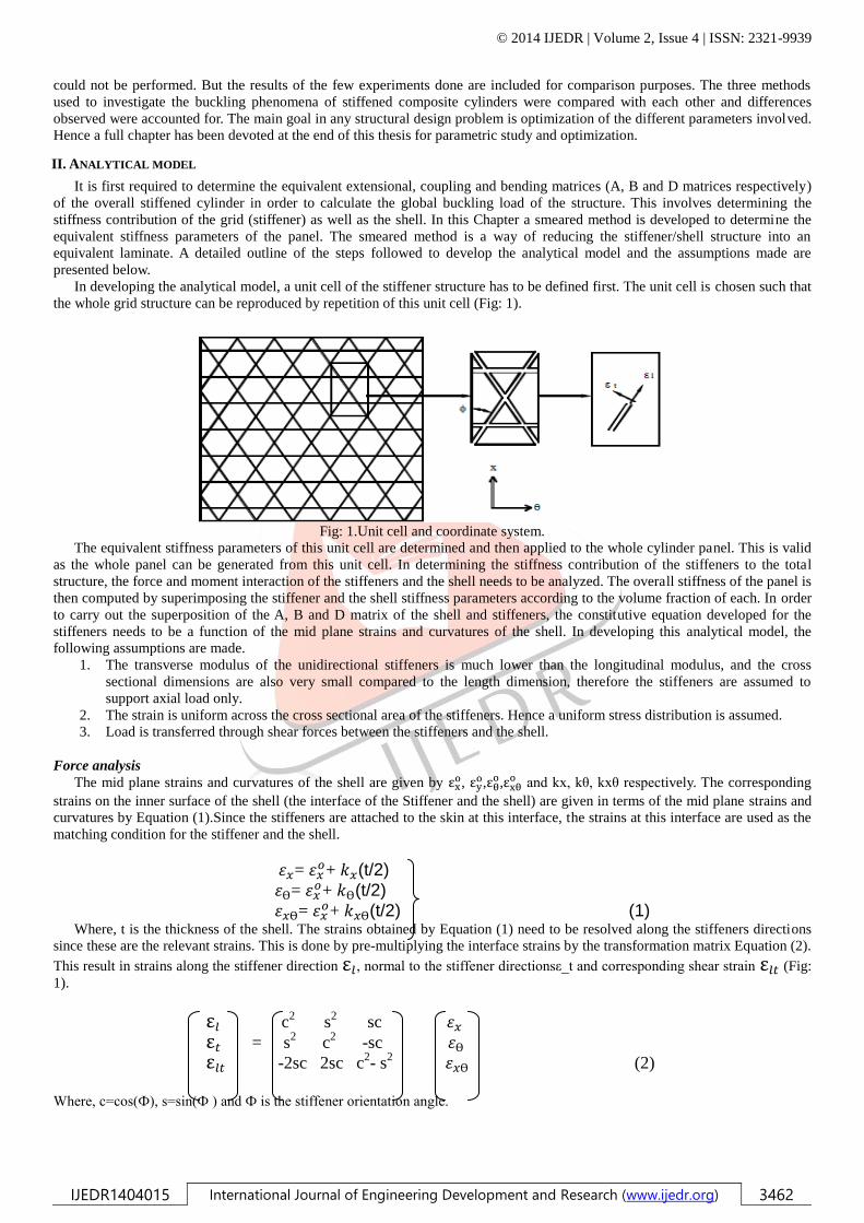
In developing the analytical model, a unit cell of the stiffener structure has to be defined first. The unit cell is chosen such that
the whole grid structure can be reproduced by repetition of this unit cell (Fig: 1).
Fig: 1.Unit cell and coordinate system.
The equivalent stiffness parameters of this unit cell are determined and then applied to the whole cylinder panel. This is valid
as the whole panel can be generated from this unit cell. In determining the stiffness contribution of the stiffeners to the total
structure, the force and moment interaction of the stiffeners and the shell needs to be analyzed. The overall stiffness of the panel is
then computed by superimposing the stiffener and the shell stiffness parameters according to the volume fraction of each. In order
to carry out the superposition of the A, B and D matrix of the shell and stiffeners, the constitutive equation developed for the
stiffeners needs to be a function of the mid plane strains and curvatures of the shell. In developing this analytical model, the
following assumptions are made.
1. The transverse modulus of the unidirectional stiffeners is much lower than the longitudinal modulus, and the cross
sectional dimensions are also very small compared to the length dimension, therefore the stiffeners are assumed to
support axial load only.
2. The strain is uniform across the cross sectional area of the stiffeners. Hence a uniform stress distribution is assumed.
3. Load is transferred through shear forces between the stiffeners and the shell.
Force analysis
The mid plane strains and curvatures of the shell are given by ε , ε
,ε ,ε
and kx, kθ, kxθ respectively. The corresponding
strains on the inner surface of the shell (the interface of the Stiffener and the shell) are given in terms of the mid plane strains and
curvatures by Equation (1).Since the stiffeners are attached to the skin at this interface, the strains at this interface are used as the
matching condition for the stiffener and the shell.
= + (t/2)
= + (t/2)
= + (t/2) (1)
Where, t is the thickness of the shell. The strains obtained by Equation (1) need to be resolved along the stiffeners directions
since these are the relevant strains. This is done by pre-multiplying the interface strains by the transformation matrix Equation (2).
This result in strains along the stiffener direction ε , normal to the stiffener directionsε_t and corresponding shear strain ε (Fig:
1).
ε c2
s2 sc
ε = s2 c
2 -sc
ε -2sc 2sc c2- s
2 (2)
Where, c=cos(Ф), s=sin(Ф ) and Ф is the stiffener orientation angle.

© 2014 IJEDR | Volume 2, Issue 4 | ISSN: 2321-9939
IJEDR1404015 International Journal of Engineering Development and Research (www.ijedr.org) 3463
In accordance to assumption (1), the effects of the transverse strain ε , and the shear Strain ε are neglected. The
longitudinal strain ε expression given below by Equation (3) is obtained from the transformation relation given by Equation (2).
ε ε ε ε (3) The appropriate angle is substituted in Equation (3) to obtain the strains along all the stiffener directions. In the case of an
isogrid stiffener arrangement these angles correspond to 00, 60
0,-60
0.
Fig: 2. Force diagram.
Once the axial strains on the stiffeners are found, the corresponding axial forces namely F1, F2, F3 are calculated from the
longitudinal strains, cross sectional area and longitudinal modulus (El) of the stiffeners. Refer to Figure 2 for the force free body
diagram of the unit cell.
Equation (4) below shows the resulting three forces.
The resultant forces on each sides of the unit cell are computed by vectorially adding the forces on the stiffeners. Summing up the
x-direction forces on either the top or bottom side of the unit cell results in Equation (5).
(5)
Similarly summing up the hoop direction forces on either left or right side of the unit cell results in Equation(6).
(6)
Expression for the shear force (Fx),, is obtained by adding the force components along any of the sides of the unit cell.
Performing this on one of the vertical sides yields Equation (7).
(7) The same shear force expression will result even if the horizontal face is used instead of the vertical face because of the
geometrical relations between „a‟, „b‟, cos (ϕ), and sin (ϕ).
Substituting Equation (4) into Equations (5), (6), (7):
ε
The resultant forces, i.e. the forces per unit length , are obtained by dividing the above force expressions by
the corresponding edge width of the unit cell. After performing this and substituting for the strain terms from Equation (1),
expressions for the resultant forces on the unit cell are obtained.
[
(
)
(
)]
[
(
)
(
)]

© 2014 IJEDR | Volume 2, Issue 4 | ISSN: 2321-9939
IJEDR1404015 International Journal of Engineering Development and Research (www.ijedr.org) 3464
*
(
)+ (9)
Moment Analysis
The moments due to the stiffeners is caused by the shear forces on the interface of the shell and the stiffeners. From
equilibrium, these shear forces equal to the forces on the stiffeners computed in the previous section. The moment caused by these
forces on the mid plane of the shell equals the forces multiplied by one half the shell thicknesses. The free body diagram in Figure
3(a) shows the different moments created by this force F. Only Msh is of main interest since it is the moment effect of the shear
forces on the shell. It can be observed from the free body diagram a net moment M results on the shell/stiffener assembly. This
moment represents the coupling of moment and force resulting from the non-symmetric structure of the shell/stiffener
arrangement.
Fig: 3(b) shows moment free body diagram of a unit cell. M1, M2, and M3 are the moments resulting from forces F1, F2, and
F3 respectively.
Fig: 3. Moments on the skin
Following the same procedure as the force analysis on a unit cell, the resultant moments on the horizontal and vertical sides of
the unit cell are computed.
(10a)
(10b)
(10c) The moments M1, M2, and M3 are calculated by multiplying the corresponding shear forces (F1, F2 and F3) by the lever arm,
which is half the thickness of the shell. Making these substitutions for the moments and dividing by the corresponding edge
lengths will result in the resultant moments. Equation (11) shows the final result after simplification.
[
(
)
(
)]
[
(
)
(
)]
[
(
)]
The Stiffness Matrix
Equations (9) and (11) are respectively the force and moment contribute ions of the stiffener, hence here forth denoted
by the superscript„s‟. These equations are summarized in a matrix form in Equation (12). The resulting matrix elements are
functions of the mid plane strains and curvatures of the shell. These were derived by analyzing the force and moments due to
stiffeners. We denote these stiffness parameters by ,
, .

© 2014 IJEDR | Volume 2, Issue 4 | ISSN: 2321-9939
IJEDR1404015 International Journal of Engineering Development and Research (www.ijedr.org) 3465
[
]
=A
[
]
[
]
(12)
At first glance the stiffness matrix given by Equation (12) might seem unsymmetrical (i.e. AijAji and DijDji), but due to the
geometric relation between the parameters „a‟, „b‟, cos (and sin () these stiffness quantities can be shown to be equal. It can
also be observed the same Bij elements result from the independent force and moment analysis on the unit cell. This is in good
agreement with laminate theory, hence further validating the initial assumptions made. The total force and moment on the panel is
the superposition of the force and moment due to the stiffener and the shell. These quantities can be directly superimposed, as the
stiffener force and moment contributions have been developed based on the mid plane strains and curvatures. The rule of mixtures
is applied and the moments and forces are superimposed according to the volume fractions of the stiffeners and the shell
(Equation (13)). Vs and Vsh stand for volume fraction of stiffener and shell respectively.
*
+ =[
] (13)
In Equation (13) Nsh
and Msh
are the force and moment contribution of the shell respectively. These quantities are easily
computed by applying the laminate theory on the shell. Substituting the force and moment expressions for the stiffener network
from Equation (12) and the corresponding expressions for the shell from the laminate theory results in the panel constitutive
equation given by Equation (14). In this equation A, B and D represent the extensional, coupling, and bending stiffness
coefficients respectively.
*
+ =[
] *
+ (14)
The resultant stiffness parameters obtained from Equation (14) are thus the equivalent stiffness parameters of the whole panel
III. FINITE ELEMENTS ANALYSIS
Modeling
A 3-D model was built for an isogrid stiffened composite cylinder using ANSYS 12 finite-elements software (Fig: 4). The
modeled cylinder has a radial symmetry of 36o. Initially one 36osector was modeled and then the whole structure was generated
using this primary sector.

© 2014 IJEDR | Volume 2, Issue 4 | ISSN: 2321-9939
IJEDR1404015 International Journal of Engineering Development and Research (www.ijedr.org) 3466
Fig: 4.Finite-elements model.
The grid structure was first developed for the primary sector and then the shell was added on to these stiffeners. The + 600
stiffeners in the primary sector were modeled by generating helical rods having outer diameter equal to the inner diameter of the
shell. The crossing over points of the stiffeners were modeled by matching the displacement of the corresponding stiffeners at
these points. This was accomplished by merging the nodes of the crossing over stiffeners at the crossover points.
The fibers in the stiffeners are oriented along the length of the stiffeners. Hence, three different real constant tables were
defined for the three stiffener orientations of 00, 60
0, and –60
0.
A local cylindrical coordinate system was then defined for each element and corresponding orthotropic properties aligned
properly. The stiffeners were modeled using 20-node, layered solid elements (SOLID 191).
The complete stiffened cylinder under discussion is manufactured by a filament winding process. The skin is made from
alternating, numerous + 300 windings. Hence the skin was modeled by a four ply laminate having a stacking sequence of [30/-
30]s. Four layers were found to be adequate to model the numerous layers from preliminary buckling analyses done on un-
stiffened cylindrical shells having different symmetric + 300 plies. The shell and stiffeners were „glued‟ at the interface, which
upon meshing automatically merges the nodes of the shell elements and the solid element on the interface area. The shell was
modeled using 8-node, layered shell element (SHELL 99).
Meshing: The shell was meshed using quadrilateral shaped elements while the stiffeners were meshed using Hexahedron shaped
elements. All the elements have mid nodes. The mesh size used is 4 mm on both shell and stiffeners. This degree of mesh size
refinement was chosen based on convergence calculations carried out (refer Section 4.5 for details). This meshing scheme results
in approximately 15,000 elements and 250,000 active degrees of freedom (Fig. 4).
Boundary Conditions and Loading
The global coordinate system of the cylinder is defined in such a way that the bottom face of the cylinder lies in the x- y plane
and the positive z-axis is aligned with the axis of the cylinder. The following boundary conditions were imposed on the cylinder.
1. The circumferential and radial displacements „v‟ and „w‟ respectively equal to zero at both faces of the cylinder (at z=0
and z=h, v=w=0).
2. Axial displacement „u‟ is zero at the bottom face of the cylinder but is non-zero at the top face where the load is applied
(at z=0, u=0 and at z=h, u=0).
A uniform unit pressure was applied on the upper rim of the cylinder (z=h). To calculate the buckling load, this unit pressure was
multiplied by the area on which the pressure was applied and by the Eigen value obtained from buckling analysis.
Solution:
Linear buckling analysis in ANSYS finite-elements software is performed in two steps. In the first step a static solution to the
structure is obtained. In this analysis the pre-buckling stress of the structure is calculated. The second step involves solving the
Eigen value problem given in the form of Equation (19). This equation takes into consideration the pre-buckling stress effect
matrix [S] calculated in the first step.
([K ] [S]){ψ}i{0} (19)
Where

© 2014 IJEDR | Volume 2, Issue 4 | ISSN: 2321-9939
IJEDR1404015 International Journal of Engineering Development and Research (www.ijedr.org) 3467
[K] = stiffness matrix
[S] = stress stiffness matrix
λi=ith Eigen value (used to multiply the loads which generated [S])
ψi= ith eigenvector of displacements The „Block Lanczos‟ method was used to extract the Eigen values resulting from Equation
(19). The Eigen values obtained from the buckling analysis are factors by which the initially applied unit force is multiplied. As a
result, the critical buckling load is calculated according to Equation (20) below.
Pcr=(i)min AP (20)
Where (i ) min = the minimum Eigen value
A = total area on which pressure is applied
P = initially applied pressure
Convergence:
Convergence of the buckling analysis was checked to validate the results obtained from the finite-elements analysis. The
convergence check was performed on a model having 75o stiffeners. The buckling load analysis for this model was done for fine
mesh (3 mm), medium mesh (4 mm) and coarse mesh (5 mm). The corresponding buckling loads resulting from these analyses
are denoted by LF, LM, and LC. These loads where substituted into the convergence criterion given by Equation (21) below.
The convergence check calculation has been summarized in Table 1. From the last column of Table 1, it can be concluded that the
analysis has converged for the model developed.
Table: 1.Convergence calculation.
LC LM LF
LC LM
LC LF
LC LM
LC LF
495,000 N 628,357 N 621,598 N 133,357 N 6,759 N YES (Converges)
It can also be observed that the buckling loads obtained for the medium and coarse mesh schemes (3 mm and 4 mm) are very
close to each other, hence a mesh size of 4 mm can be used without considerable loss of accuracy. Based on this conclusion a
mesh size of 4 mm was adopted for all models built.
Analyses Result:
Finite-elements analysis was performed for an isogrid stiffened composite cylinder having the properties shown in Table 2. To
study the three buckling failure modes, different analyses were run by varying the skin thickness of the shell while maintaining
the same configuration of stiffeners. The skin thickness was varied from 0.3 mm to 4 mm. The observations made on these
analyses are presented in the following section.
Table: 2.Physical property of model.
Composite System IM7/977-2
Cylinder height 180 mm
Cylinder diameter 146 mm
Shell winding angle +30o
Stiffeners orientation 0o, +60
o, -60
o
Horizontal stiffener spacing 38.5 mm
Cross stiffeners spacing 42.5 mm
Shell thickness 0.3 mm
Stiffener cross section 6x2.8 mm2
IV. FAILURE MODES
The cylinder with the thinnest shell thickness of 0.3 mm was observed to fail purely due to local skin buckling (Fig: 5). When
the skin thickness was increased, the failure mode gradually changed to global buckling at about 1.5 mm skin thickness. At this
point in addition to local buckling of the skin, the adjacent stiffeners started to buckle as well. With further skin thickening of the
shell, the localized skin and stiffener failure spread to adjacent cells and gradually transformed to a more global buckling failure
mode (Fig: 6). At about a skin thickness of 3 mm, the shell was observed to be relatively stronger than the stiffeners and hence
localized stiffener crippling started to occur. For any skin thickness more than 3 mm the local stiffener crippling failure mode
prevailed (Fig: 7). It should be noted that the global buckling failure mode observed is not fully developed as would result from a
monocoque (unstiffened) cylinder. The failure is hence somewhat localized to a certain portion of the cylinder. It is also observed
that there is no unique point at which the failure modes abruptly switch over to the next buckling failure mode but rather go
through some transitional mixed buckling failure modes.
LC LM LC LF (21)

© 2014 IJEDR | Volume 2, Issue 4 | ISSN: 2321-9939
IJEDR1404015 International Journal of Engineering Development and Research (www.ijedr.org) 3468
Fig: 5.Local skin buckling
Fig: 6.Global buckling.
V. EXPERIMENTATION
In the previous two chapters, two models were developed for buckling investigation of grid-stiffened composite cylinder
structures. In order to measure the accuracy of these models, experimental verification is required.
Test Specimen:
The buckling test was performed on an isogrid stiffened composite cylinder. Both the shell and the stiffener of the specimen
were integrally made by filament winding process. To avoid material build up at the nodes, the horizontal stiffeners are positioned
offset from the intersection point of the cross stiffeners. Fig: 7 shows a picture of the specimen.
© 2014 IJEDR | Volume 2, Issue 4 | ISSN: 2321-9939
IJEDR1404015 International Journal of Engineering Development and Research (www.ijedr.org) 3469
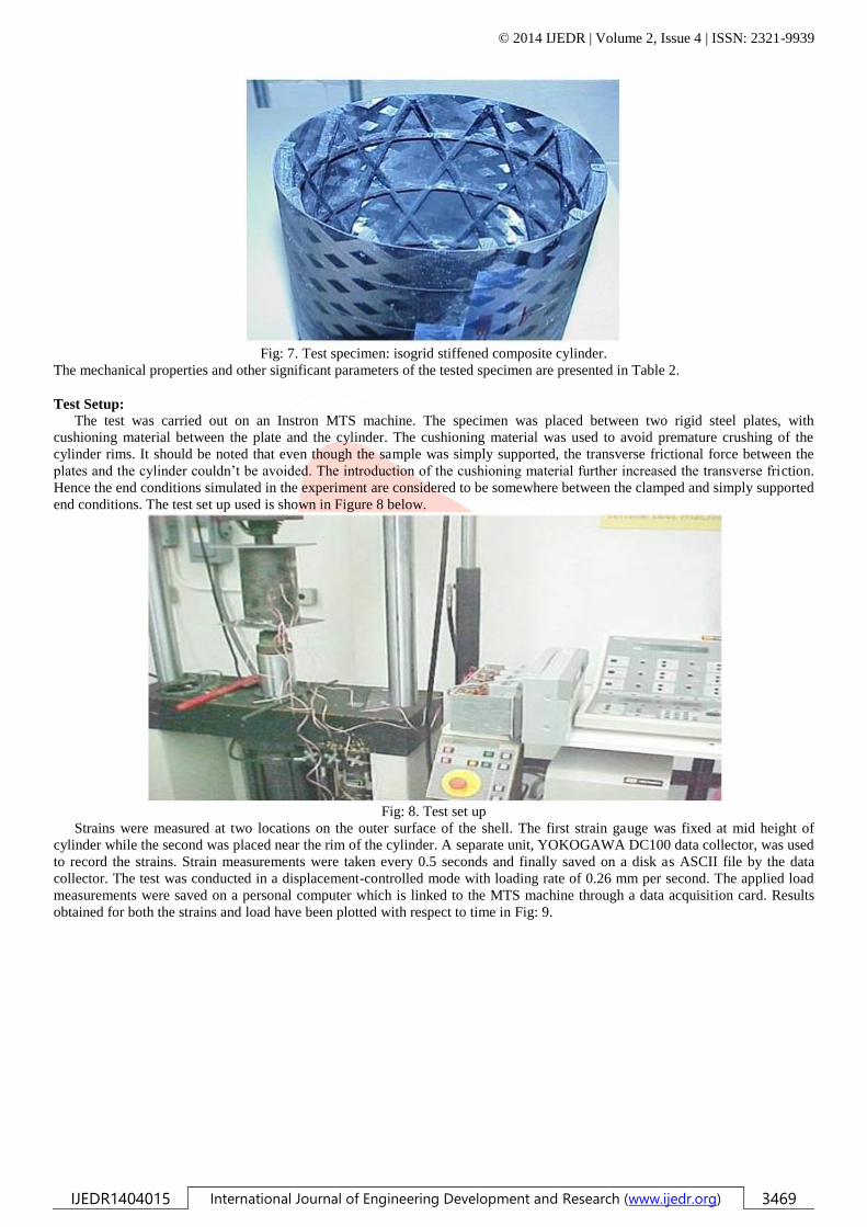
Fig: 7. Test specimen: isogrid stiffened composite cylinder.
The mechanical properties and other significant parameters of the tested specimen are presented in Table 2.
Test Setup:
The test was carried out on an Instron MTS machine. The specimen was placed between two rigid steel plates, with
cushioning material between the plate and the cylinder. The cushioning material was used to avoid premature crushing of the
cylinder rims. It should be noted that even though the sample was simply supported, the transverse frictional force between the
plates and the cylinder couldn‟t be avoided. The introduction of the cushioning material further increased the transverse friction.
Hence the end conditions simulated in the experiment are considered to be somewhere between the clamped and simply supported
end conditions. The test set up used is shown in Figure 8 below.
Fig: 8. Test set up
Strains were measured at two locations on the outer surface of the shell. The first strain gauge was fixed at mid height of
cylinder while the second was placed near the rim of the cylinder. A separate unit, YOKOGAWA DC100 data collector, was used
to record the strains. Strain measurements were taken every 0.5 seconds and finally saved on a disk as ASCII file by the data
collector. The test was conducted in a displacement-controlled mode with loading rate of 0.26 mm per second. The applied load
measurements were saved on a personal computer which is linked to the MTS machine through a data acquisition card. Results
obtained for both the strains and load have been plotted with respect to time in Fig: 9.

© 2014 IJEDR | Volume 2, Issue 4 | ISSN: 2321-9939
IJEDR1404015 International Journal of Engineering Development and Research (www.ijedr.org) 3470
Fig: 9.Experimental results.
Test Result:
The result plot in Fig: 10 shows two sharp peaks in the load and the strain measurements. The first peak which occurred at 46.7
KN was observed to be a localized failure of the skin around the lower rim of the cylinder. This is analogous to the local skin
buckling failure mode described in the introduction part of this paper. The specimen was further loaded and a drop in the load was
observed. This drop of load occurs due to stress redistribution after the local failure occurs. With further loading of the stiffened
cylinder, the load gradually increased and reached the second peak at about 88 KN. At this point the specimen failed in global
buckling failure mode, and the load dropped sharply. Fig: 10 shows pictures of specimen after this global failure.
Fig: 10.Specimen after failure.
VI. RESULTS AND DISCUSSION
In this Chapter comparison of the three different approaches used to calculate buckling load is presented. The comparison is
based on analysis performed on the specimen having the properties given in Table 2. These dimensions and configurations were
chosen based on the stiffened composite specimen used for experimentation. Since comparison of all three methods at the same
time can be confusing, first the experimental result is compared with the results obtained using the smeared model and the finite-
elements model. Then the smeared model and finite-elements model are compared.
Experimental vs. Analytical Models Result Comparison:
In chapter five, the failure mode of the specimen was established to be in local skin buckling failure mode. The analytical model
developed using smeared approach can only predict global failure modes of a stiffened composite cylinder. Hence, direct
comparison of results between the smeared model solution and experimentation is not possible. On the other hand the finite-
elements model built was shown to predict all three types of failure modes of the stiffened composite cylinder. The result of the
finite-elements analysis performed on the model built for the specimen showed that the specimen fails in local skin buckling
failure mode at a load of 44.9 KN. Figure 5 depicts the failure mode of the specimen from the finite-elements analysis. The finite-
element result obtained is within 2.5% deviation from the experimentally found load of 46 KN. Considering the errors that can
result from discretization and other sources, we can say the finite-elements analysis accurately models the specimen
Smeared Model vs. Finite-elements Model Result Comparison:

© 2014 IJEDR | Volume 2, Issue 4 | ISSN: 2321-9939
IJEDR1404015 International Journal of Engineering Development and Research (www.ijedr.org) 3471
In Section 6.1 the finite-elements model was verified using experimental results. In this section accuracy of the smeared model
is gauged by comparing its results with that of the verified finite-elements model.
The smeared analytical model reduces the whole stiffener/shell panel to an equivalent laminate. The buckling load computed
hence assumes a global buckling failure mode. The buckling modes resulting from the smeared model are fully developed lobes
both in the hoop and axial direction, since continuous displacement fields were assume.
The buckling load variation with the skin thickness for both finite-element analysis and smeared model is presented in Figure
11. The results for both models are based on calculations made on simply supported models. All parameters are kept the same for
both the smeared model and the finite-element model, with cross stiffeners oriented at +600. The error plot (the deviation of
smeared model results compared to results obtained using finite-elements analysis) shows that the two analytical models predict
almost the same values of buckling load in the global buckling failure mode range. While in the two local failure regions, the
smeared model predicts different buckling loads compared to the finite-elements model. This occurs because the equivalent
orthotropic cylindrical shell developed using the smeared method will only fail in global buckling failure mode as opposed to the
distinct three buckling failure modes occurring in the actual stiffened cylindrical structure. These observations show that the
smeared model predicts global buckling failures precisely and confirms that the smeared model cannot be used to analyze local
failures.
Fig: 11.Analytical vs. finite-elements result comparison
VII.PARAMETRIC STUDY
The accuracy of the finite-elements model was first verified using experimental results. Then the finite-elements results were
used as a benchmark to verify the accuracy of the smeared model developed. Once the accuracy of the smeared model and the
finite-elements model was established, parametric study was performed on the different design variables. In this Chapter the
effect of shell thickness, shell winding angle, longitudinal modulus and stiffeners orientation angle on buckling load is presented.
Caution should be taken whenever using the smeared analytical model for optimization purposes. This method is exclusively
developed for prediction of global failure modes. On the other hand when certain design parameters are varied the failure modes
tend to switch over from one kind to another. A good example is the effect of skin thickness. As the skin thickness is increased
the failure mode of the stiffened cylinder was shown to change from local skin buckling to global buckling and then to stiffener
crippling. Hence, the smeared model cannot be used in this case. In order to use the smeared model without the limitations
described, it needs to be used in conjunction with other analytical tools that are able to predict the local failure modes. For the
above- mentioned reasons, most of the parametric study is carried out using the finite-elements model.
Effect of Shell Thickness
The effect of shell thickness on buckling load was investigated using the finite-elements model. Eight analyses were performed
to smoothly increase the skin thickness from 0.3 mm to 4 mm. Figure 12 shows plot of the results obtained from these analyses.

© 2014 IJEDR | Volume 2, Issue 4 | ISSN: 2321-9939
IJEDR1404015 International Journal of Engineering Development and Research (www.ijedr.org) 3472
Fig: 12.Effect of skin thickness.
It is observed that the buckling resistance of the stiffened cylinder steadily increases with increase in shell thickness. Even
though a steady increase in buckling load is observed with skin thickness increase, the gain per unit weight added reaches a
maximum and then declines after a certain point. This gain per unit weight, here forth referred to as „specific load‟, measures the
efficiency of the weight added, i.e., the additional load carried by the added weight. For the analysis performed on the isogrid
stiffener arrangement the optimum skin thickness at which the specific load reaches maximum is found to be 2.2 mm. It can be
observed from Figure 12 that this optimum skin thickness lies approximately in the middle of the global buckling failure mode
region. This result is very significant as it confirms the observation of other researches that only global buckling failure mode
results in the maximum specific buckling load, and consequently leads to the conclusion that global buckling failure mode should
be the design criteria for a stiffened cylinder.
Effect of Shell Winding Angle:
Shell winding angle is one of the design variables that can be easily varied using the finite-elements model. The shell winding
angle can be varied by just changing the inputs of the real constants table, without changing the model. The effect of shell
winding angle was investigated for the three types of buckling failure modes. The analysis was performed on models having skin
thickness of 0.3 mm, 2.5 mm and 4 mm. These three skin thickness correspond to local skin buckling, global buckling and
stiffener crippling failure modes respectively. The analyses results are presented in Figure 13 below.
Fig: 13.Effect of shell winding angle
It can be observed that shell winding angle variation has different effects on each type of failure modes. For local skin
buckling failure mode, which corresponds to 0.3 mm skin thickness curve, increase in shell winding angle decreases the load
resistance of the structure. The effect of shell winding angle on a stiffened cylinder failing in stiffener crippling failure mode is
contrary to this. The buckling load resistance increases steadily with winding angle increment. On the other hand, for global
buckling failure mode, with increase in shell winding angle the load resistance of the structure first increases and then goes down
after reaching a maximum. Hence we can conclude there exist an optimum shell winding angle for a stiffened cylinder failing in

© 2014 IJEDR | Volume 2, Issue 4 | ISSN: 2321-9939
IJEDR1404015 International Journal of Engineering Development and Research (www.ijedr.org) 3473
global buckling failure mode. The optimum shell winding angle for a stiffened cylinder having a skin thickness of 2.5 mm is
found to be about 540.
Effect of Stiffener Orientation
The effect of the stiffener orientation was also studied using the finite element model. Four models having cross stiffener
orientation angle of 300, 45
0, 60
0 and 75
0 were built for this purpose. The hoop direction is taken as a reference for stiffener
orientation angle measurement. In all the four models the total weight of the stiffened cylinder was maintained the same. The
result obtained has been summarized in Figure 14 below
Fig: 14.Effect of stiffener orientation
It can be observed that the buckling resistance of the stiffened cylinder increases when the stiffeners orientation angle is
increased. This is reasonable since the applied load is uniaxial and the structure gets stiffer in the axial direction when the
stiffener orientation angle is increased.
Effect of Modulus:
The main advantage of developing a closed form analytical solution like the one obtained using the smeared model is the ease
with which parametric study can be performed. To demonstrate this advantage, the effect of modulus on the buckling load of an is
grid stiffened composite cylinder was investigated using the smeared model developed. The analysis was performed for a wide
range of skin thickness. It has been shown in Section 7.1 that buckling failure mode highly depends on the skin thickness. As a
result the actual failure modes associated with some of the models analyzed might be different from global buckling failure mode.
Hence this parametric analysis should only be used to appreciate the use of the smeared analytical model developed and to have a
general idea of the effect of modulus on buckling load.The longitudinal modulus of the composite system was varied from
145Gpa to 192Gpa. The effect of modulus was studied on cylinders having shell thickness varying from 0.3 mm to 4 mm. Figure
15 below summarizes the results obtained.
Fig: 15.Effect of modulus.
The buckling load was observed to increases linearly with increase in longitudinal modulus for all skin thickness. It appears
from the plot that the gain in buckling resistance increases as the skin thickness increases. But a close look at Table 3, which
tabulates the percentage gain in the buckling load with increase in modulus, shows a higher gain in buckling load is obtained for
lower skin thickness.

© 2014 IJEDR | Volume 2, Issue 4 | ISSN: 2321-9939
IJEDR1404015 International Journal of Engineering Development and Research (www.ijedr.org) 3474
Table 3. Gain in buckling load with modulus increase.
Skin thickness 0.3 mm 0.5 mm 1 mm 1.5 mm 2 mm 2.5 mm 3 mm 4 mm
% Load gain 26.0 25.7 24.9 23.8 22.1 21.8 20.2 17.7
Hence it can be concluded that a better gain in buckling load resistance is achieved if the longitudinal modulus is increased for
a stiffened cylinder failing in local skin buckling failure mode than for a stiffened cylinder failing in a stiffener crippling failure
mode.
VII. CONCLUSION
A smeared stiffener analytical model was successfully developed for the investigation of buckling problems of stiffened
composite cylinders. This analytical model is robust in that it can be used to predict the global buckling loads of composite
cylinders stiffened either on one side or both sides. Finite-elements analysis and experimentation were carried out to assess the
reliability of this analytical model. Based on comparisons made, the analytical model developed has been found to be very
accurate in predicting the global failure loads of stiffened composite cylinders. The different failure modes of a stiffened
composite cylinder were also studied in detail. These studies showed that the efficient utilization of material (load resistance per
unit weight) highly depends on the buckling failure mode of the cylinder structure. For an isogrid stiffened cylinder, failure in
global buckling mode resulted in the highest specific buckling load. Based on the analytical models developed, parametric study
was performed on some of the design variables involved in stiffened composite cylinders. The parameters investigated were skin
thickness, skin winding angle, stiffener orientation angle and longitudinal modulus.
Increase in skin thickness was shown to increase the buckling resistance of the stiffened structure continuously. But an
optimum skin thickness of 2.2 mm was observed to result in the highest specific buckling load. The variation in shell winding
angle was observed to have different effects on stiffened cylinders failing in different failure modes. For a stiffened cylinder
failing in local skin buckling failure mode, increase in winding angle decreases the load resistance of the structure. While for a
stiffened cylinder failing in stiffener crippling failure mode, improvement in load resistance is noted with increase in shell
winding angle. For a stiffened cylinder failing in global buckling failure mode an optimum shell-winding angle of 540 was
observed.
The effects of both stiffener orientation angle and longitudinal modulus increase were observed to continuously increase the
buckling resistance of the stiffened cylinder structure.
REFERENCES
[1] Jaunky N., Knight N.F., Ambur D.R., “Optimal Design of General Stiffened Composite Circular Cylinders for Global
Buckling With Strength Constraints,” Composite Structures, March 1998.
[2] Helms J.E., Li G., Smith B.H., “Analysis of Grid Stiffened Cylinders,” ASME/ETCE 2001.
[3] Black S., “A Grid-Stiffened Alternative to Cored Laminates,” High-Performance Composites, March 2002.
[4] Jaunky N., Knight N.F., Ambur D.R., “Formulation of An Improved Smeared Stiffener Theory of Buckling Analysis of Grid-
Stiffened Composite Panels,” NASA technical Memorandum 110162, June 1995.
[5] Phillips J.L., Gurdal Z., “Structural Analysis and Optimum Design of Geodesically Stiffened Composite Panels,” NASA
Report CCMS-90-05, July 1990.
[6] Gerdon G., Gurdal Z., “Optimal Design of Geodesically Stiffened Composite Cylindrical Shells,” AIAA Journal, November
1985; 23(11): 1753-1761.
[7] Jaunky N., Knight N.F., Ambur D.R., “Optimal Design of Grid-Stiffened Composite Panels Using Global and Local
Buckling Analysis,” Journal of Aircraft, Vol. 35, No. 3, May-June 1998.
[8] Wang J.T.S., Hsu T.M., “Discrete Analysis of Stiffened Composite Cylindrical Shells,” AIAA J. 1995, 23, 1753-1761.
[9] Knight N.F., Stranes J.H., “Development in Cylindrical Shell Stability Analysis,” NASA report, 1997.
[10] Graham J., “Preliminary Analysis Techniques for Ring and Stringer Stiffened Cylindrical Shells,” NASA report TM-108399,
March 1993.
[11] Hilburger M.W., “Nonlinear and Buckling Behavior of Compression- loaded Composite Shells,” Proceedings of the 6th
Annual Technical Conference of the American Society for Composites, Virginia 2001.