
Fuselage System Layout
8
Automatic Fuselage System Layout using Knowledge Based Design Rules Jörg Fuchte * , Björn Nagel * , Volker Gollnick * Abstract This paper introduces a tool for preliminary system placement inside an aircraft’s fuselage. Objective is to estimate the effect of design decisions on system routing, which may then be used for better weight estimation or physical modeling. The method uses a detailed geometrical model of the fuselage including cabin and primary structure. The system components and connectors are placed according to knowledge patterns. The focus is on large fuselage systems such as the environmental control system, the water&waste system and parts of the electrical system, which are the most significant in terms of size and weight. Abbreviations AC Alternating Current APU Auxiliary Power Unit CPACS Common Parametric Aircraft Configuration Scheme DC Direct Current DMU Digital Mock-Up ECS Environmental Control System EPS Electrical Power System FCS Flight Control System MOA More Electric Architecture resp. Aircraft WWS Water&Waste System PC Power Center 1 Introduction This section outlines the motivation and scope of the work. Further recent publications concerning the subject are listed. 1.1 Motivation System architecture in current aircraft design follows long established patterns. It is of major importance for the design of the fuselage as the systems affect the overall arrangement of it. Cabin and cargo hold occupy the major- ity of space inside the pressurized fuselage, leaving only scarce fractions of the space for system components and routing. Systems are consequently placed whereever they fit best, while some systems are more flexible than others when it comes to location. Some can be placed with small penalty anywhere in the fuselage, for example electronic system components. Other systems are more constrained. Systems such as the environmental control system (ECS), the water&waste system (WWS) and the electrical power system (EPS) have substantial requirement for connectors and ducts. These connectors and ducts may transport electricity, water or compressed aircraft. They occupy a substantial volume inside the fuselage and they reduce the effectiveness of the system itself through pressure loss or electric resistance. A better understanding of the effect of system component placement on the routing is desirable. A detailed routing may be useful for various aspects of aircraft design, for example: 1. The knowledge of discrete routes allows an estima- tion of the weight of these connectors and hence al- lows trade studies to find a multi-disciplinary opti- mum. 2. The routing influences the system’s performance through pressure losses, which again influences sys- tem’s weight and energy consumption. 3. Space inside the fuselage is limited and the arrange- ment of system connectors needs to adapt to chang- ing aircraft configurations. Alternative system ar- rangements can be studied and assessed. The introduced method studies the effect of changing ar- chitecture on fuselage design. The method creates a pre- liminary digital mock-up (DMU) that includes the systems with the highest requirement for volume. This allows to identify the a suitable architecture in early stages of the design. Possible applications include new system tech- nology such as fuel cells, different engine location or new concepts like displacement ventilation. Another important information is the position of possible heat sources inside the fuselage that require cooling. 1.2 Scope of the Work The introduced method creates a system architecture of the environmental control system, parts of the electrical power system and the water&waste system. This includes the position of major components, the route of ducts and other connectors and interfaces to the cabin or other parts of the airframe. The routes are found using an algorithm for identification of available space and a detailed model of the fuselage. The routes follow knowledge patterns for system placing based on current technology aircraft. The * Lufttransportsysteme, DLR e.V., Blohmstrasse 18, 21079 Hamburg, Deutschland
Transcript of Fuselage System Layout
Automatic Fuselage System Layout using Knowledge Based Design Rules
Jörg Fuchte∗, Björn Nagel∗ , Volker Gollnick∗
AbstractThis paper introduces a tool for preliminary system placement inside an aircraft’s fuselage. Objective
is to estimate the effect of design decisions on system routing, which may then be used for better weightestimation or physical modeling. The method uses a detailed geometrical model of the fuselage includingcabin and primary structure. The system components and connectors are placed according to knowledgepatterns. The focus is on large fuselage systems such as the environmental control system, the water&wastesystem and parts of the electrical system, which are the most significant in terms of size and weight.
Abbreviations
AC Alternating CurrentAPU Auxiliary Power UnitCPACS Common Parametric Aircraft
Configuration SchemeDC Direct CurrentDMU Digital Mock-UpECS Environmental Control SystemEPS Electrical Power SystemFCS Flight Control SystemMOA More Electric Architecture resp. AircraftWWS Water&Waste SystemPC Power Center
1 Introduction
This section outlines the motivation and scope of thework. Further recent publications concerning the subjectare listed.
1.1 Motivation
System architecture in current aircraft design follows longestablished patterns. It is of major importance for thedesign of the fuselage as the systems affect the overallarrangement of it. Cabin and cargo hold occupy the major-ity of space inside the pressurized fuselage, leaving onlyscarce fractions of the space for system components androuting.Systems are consequently placed whereever they fit best,while some systems are more flexible than others when itcomes to location. Some can be placed with small penaltyanywhere in the fuselage, for example electronic systemcomponents. Other systems are more constrained.Systems such as the environmental control system (ECS),the water&waste system (WWS) and the electrical powersystem (EPS) have substantial requirement for connectorsand ducts. These connectors and ducts may transportelectricity, water or compressed aircraft. They occupy asubstantial volume inside the fuselage and they reduce theeffectiveness of the system itself through pressure loss or
electric resistance. A better understanding of the effect ofsystem component placement on the routing is desirable.A detailed routing may be useful for various aspects ofaircraft design, for example:
1. The knowledge of discrete routes allows an estima-tion of the weight of these connectors and hence al-lows trade studies to find a multi-disciplinary opti-mum.
2. The routing influences the system’s performancethrough pressure losses, which again influences sys-tem’s weight and energy consumption.
3. Space inside the fuselage is limited and the arrange-ment of system connectors needs to adapt to chang-ing aircraft configurations. Alternative system ar-rangements can be studied and assessed.
The introduced method studies the effect of changing ar-chitecture on fuselage design. The method creates a pre-liminary digital mock-up (DMU) that includes the systemswith the highest requirement for volume. This allows toidentify the a suitable architecture in early stages of thedesign. Possible applications include new system tech-nology such as fuel cells, different engine location or newconcepts like displacement ventilation. Another importantinformation is the position of possible heat sources insidethe fuselage that require cooling.
1.2 Scope of the Work
The introduced method creates a system architecture ofthe environmental control system, parts of the electricalpower system and the water&waste system. This includesthe position of major components, the route of ducts andother connectors and interfaces to the cabin or other partsof the airframe. The routes are found using an algorithmfor identification of available space and a detailed modelof the fuselage. The routes follow knowledge patterns forsystem placing based on current technology aircraft. The
∗Lufttransportsysteme, DLR e.V., Blohmstrasse 18, 21079 Hamburg, Deutschland

routing algorithm places connectors under considerationof available space inside a particular part of the fuselage.The routing is performed only in the pressurized part ofthe fuselage. Systems such as hydraulics or flight controlsare excluded during this initial development step.The tool is developed in Matlab. Even the standard plotfunctions allow a CAD-like visualization of the resultingsystem routing. A CAD-interface is not implemented butas shown in [12], an interface between Matlab and CATIAcan be established quickly.
1.3 State of the Art
The estimation of system properties is well established inpreliminary aircraft design. Depending on the purpose dif-ferent modeling approaches exist. Several works publishedmethods for estimation of aircraft system weight by usingmore advanced physical models. Koeppen [4] introducedsuch a method for preliminary aircraft design. Dollmayer[13] used advanced models to estimate the effect of systemenergy consumption on aircraft performance. A similarapproach is pursued by Lammering [14] focusing on theenergy consumption of the systems. Lüdders [9] studiedthe effect of a fuel cell. All mentioned works include therequired energy of the system in their model. Geometricalproperties are only partly considered. Koeppen considersthe weight of the ducts and connectors.
Several other methods and tools exists. The introducedtool is hence not the first of its kind. The difference toexisting tools and methods is that the routing is done fullyautomatic within a preliminary design loop. Hence it canbe used to study the influence of overall aircraft designdecisions on system design, and vice versa the influence ofsystem design decision on aircraft performance. Currentlysuch trade studies are performed using simplified CADtools. The method can be understood as supplement forexisting methods, introducing more information about theconnectors and allowing a more precise modeling of thephysical properties of the system.
System architecture is only partly covered in aircraft de-sign textbooks. A notable exception is the fourth volumeof Roskam’s Aircraft Design series [10], which featuressketches of system architecture for the B767 and someother designs.
2 System Architecture
This section explains the current state-of-the-art in systemarchitecture and also indicates at which point future air-craft might deviate from this architecture.
2.1 General
System architecture describes the arrangement of the sys-tem components. Each system has a source. That is, it doesreceive something from a particular point of the aircraft.
This may be pressurized air from the engine, ram air froman air inlet or electrical power or the fresh water from thefresh water tank. Each system then has components thatprocess, distribute or rearrange the particular system’s re-source. These components can have boundary conditionsconcerning their position inside the fuselage. Each systemfurther has sinks which locations are either dictated bythe cabin and airframe arrangement or represent anotherdegree of freedom for the system. In the following thesources, components and sinks are described for each ofthe three considered systems.
2.2 Environmental Control System - ECS
The Environmental Control System (ECS) is responsiblefor the provision of a survivable atmosphere inside thecabin. This includes the control of a minimum air pres-sure and the regulation of the temperature. As passengersadd heat, water vapor and consume oxygen, the air in-side the cabin needs to be recirculated, dehumidified andexchanged constantly. The ECS receives fresh air from out-side the aircraft through ram air inlets. Heat and energyare taken from the engines’ compressor as bleed air. Thehot and cold air are mixed in the air conditioning packs,which are located outside the pressurized fuselage. Thepacks transmit the breathable air to the mixer unit, whichalso receives recirculated air from inside the cabin. Fromthe mixer unit ducts lead to various parts of the cabin andend inside the cabin. The architecture of the ducts mayvary depending on design decisions and the number oftemperature zones. A temperature zone is a zone that canbe set to a particular temperature. Aircraft have betweentwo (single aisle) and five (large widebody) temperaturezones. The cockpit and the cargo hold are fed separately.The ECS ducting requires substantial volume. As air inletsin the cabin are usually placed overhead the passengers,the air needs to be ducted into the upper part of the cabin.This requires so-called riser ducts, which may require thedeletion of windows. Figure 1 shows the fresh air ducts ofthe A320. Note the arrangement with local riser ducts. [7][6]
Figure 1: Fresh Air Ducting in the A320 (from [1])
2

2.3 Electrical Power System - EPS
The electrical power system (EPS) includes both the directcurrent (DC) and alternating current (AC) system. Electri-cal power is required in almost every part of the aircraft,and hence the system is of considerable complexity. Forthis work only a limited number of components is consid-ered. Current EPS use so called power centers to distributethe electrical power received from the generators. Thesepower centers distribute the power to all consumers insidethe fuselage. Large consumers of electrical power usuallyuse AC power, but many small consumers inside the cabinrequire DC power. Electrical components also produceexcess heat. Traditionally the power center is placed inthe forward part of the aircraft, in the room below thecockpit and in front of the forward cargo hold. New EPSconcepts ("More Electric Architecture" - MOA) require asubstantially more powerful electrical system and hencelarger and heavier power center. The B787 - which useselectrical power instead of bleed air for its ECS - has twopower centers, of which one is located behind the landinggear bay. [6] [3]
2.4 Water & Waste System - WWS
The Water & Waste System (WWS) is required for the gal-leys and lavatories. While small commercial and businessaircraft sometimes omit such a system, commercial aircraftwith 100 and more seats require them. The source of thefresh water is the fresh water tank, which is always locatedinside the pressurized fuselage. From the fresh water tankgalleys and lavatories are supplied. The pipes are rela-tively small in diameter. The waste water is ducted backto the waste water tank. As underpressure is used to suckthe waste water into the waste tank, the ducting for thewaste water is more constrained. The exact position ofthe galleys and lavatories depends on the particular cabinlayout, while their position is constrained to zones insidethe cabin. [8]
2.5 Other Systems
The systems that are not considered include the hydraulics,the fuel system, the bleed air system, flight controls andcommunication and entertainment systems. The bleed airsystem connects the engines with the auxiliary power unitand is limited to a single duct inside the fuselage. Hy-draulics run through the fuselage to supply the nose gear,the cargo doors and the empenage control systems. Thehydraulic components are limited to pipes with small di-ameter. Most major components of the hydraulic systemare placed inside the landing gear bay. The fuel system islike the bleed air system limited to a connection betweenthe wings and the empenage, where the APU requiresfuel or additional fuel tanks are located. Flight controlsinclude cables in case of conventional aircraft and wiresin case of fly-by-wire aircraft. Modern aircraft omit anycable-based flight controls, so that flight controls inside
the fuselage are limited to wires transmitting low energybinary or analogue information ([2]). Communication andentertainment systems add considerable amount of wiresas sources and sinks are widely distributed over the cabinand fuselage. The fact that low-energy analogue or digitalinformation is transmitted allows a flexible routing. Oftenseveral types of wires are concentrated in so-called race-tracks.
3 Tool Description
3.1 Fuselage Modeling
The positioning of system components depends on the geo-metrical characteristics of the fuselage. That is, componentlocation and routing adapt to the specific geometry of aparticular fuselage. Therefore a detailed knowledge of thefuselage and all its components is necessary. This includesthe cabin with the monuments and overhead stowage bins.Further structural features such as doors, vertical struts,wing box and landing gear bay. Many systems are locatedbelow the main deck in the unused volume between theskin and the cargo hold. Therefore the cargo hold needs tobe defined.
The basis for the fuselage model can vary. One optionis the usage of a CPACS-inputfile defining an aircraft con-figuration (see [5]). CPACS provides sufficient informationfor the arrangement of the fuselage. The usage of a CPACSinterface allows the interaction with other tools in the air-craft design process.
For that purpose a fuselage layout tool is used, whichis also used for other applications (see [12] and [11]). Thetool generates a detailed three-dimensional model of thefuselage and the cabin. The model is used to generate ageometry for the system layout. When looking at the crosssection, the areas left and and right of the vertical struts(so called triangle area) are available for systems. Furtherthe area below the cargo floor and the area above the cabin(crown area). The main deck floor beams are used formany cables and wires, but are unable to accommodateanything larger. For the path finding the unused areas aremapped at each frame position. Figure 2 shows a typicalcross section of a single aisle. Larger cross sections usuallyoffer more surplus space.
3

Figure 2: Single Aisle Cross Section
3.2 Placement of Large Components
Large components such as the mixer unit, the water andwaste tanks and the power center have a limited numberof possible locations. The mixer unit for example can belocated in front of the wing box, but also behind the mainlanding gear bay. Using design rules derived from currenttechnology aircraft the components are sized and adaptedto the local constraints. The placement therefore repre-sents an application of knowledge-based engineering. Theconsideration of different locations for a component (forexample the fresh water tank) is cumbersome as geomet-ric constraints are different each time. These need to becoded and tested. Figure 3 shows a possible location ofthe waste water tanks. They are located in the rear part ofthe fuselage, beneath the main deck and between the rearend of the cargo hold and the pressure bulkhead. Tanksare constrained by the structural layout. Such knowledgepatterns need to be identified from current aircraft, andintegrated into the tool. Although cumbersome, no realalternative exists.
Figure 3: Location of waste water tanks in rear fuselage.
3.3 Path Finding Algorithm for SystemConnections
When major components are placed the system connec-tions are created. Connections are defined by a start and an
end coordinate. The path finding algorithm finds a route inthe selected area (triangle, crown, underfloor) and blocksthe required volume at each frame location. The areas areseparated into squares of 2.54cm length (one inch).
Figure 4: Discretization of triangle area for path finding
The algorithm uses a mapped field of the respectivearea. Each field in the 2D-matrix represents an area, whichis either blocked or free. Figure 4 gives an approximate im-pression how this mapping works. The algorithm searches- depending on settings from bottom to top or vice-versa- the field for a spot sufficiently large to place the duct.The used nodes are then blocked for follow-up searches.The minimum area any duct or wire can occupy is a singlenode, hence the node length is of importance. An im-portant limitation is that all ducts occupy a square field,although the majority are actually of circular profile.
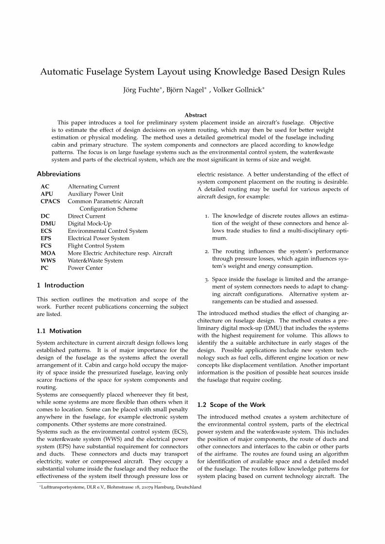
In case of the ECS the mixer unit needs to be connectedto the individual air outlets in the cabin. Each temperaturezone is connected to the mixer unit via an individual duct.Often the ducts are separated into left and right side. Theair outlets are all above the the seats, so that the air needsto ducted upwards. The cabin sidewall leaves only limitedroom. The problem is solved either by a number of indi-vidual riser ducts (A320 family) or by a single large riserduct (B737). The latter has the disadvantage that a windowneeds to be deleted. In figure 5 the ECS and WWS ductingin a single aisle cross section is depicted. Note the riserducts at every second frame.ECS ducts are also sized in diameter in dependence of theair flow required. Maximum allowable flow velocities canbe defined for different types of ducts.
4
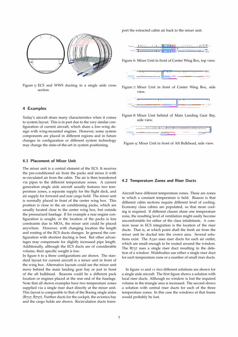
Figure 5: ECS and WWS ducting in a single aisle crosssection
4 Examples
Today’s aircraft share many characteristics when it comesto system layout. This is in part due to the very similar con-figuration of current aircraft, which share a low-wing de-sign with wing-mounted engines. However, some systemcomponents are placed in different regions and in futurechanges in configuration or different system technologymay change the state-of-the-art in system positioning.
4.1 Placement of Mixer Unit
The mixer unit is a central element of the ECS. It receivesthe pre-conditioned air from the packs and mixes it withre-circulated air from the cabin. The air is then transferredvia pipes to the different temperature zones. A currentgeneration single aisle aircraft usually features two tem-perature zones, a separate supply for the flight deck, andair supply for forward and rear cargo hold. The mixer unitis normally placed in front of the center wing box. Thisposition is close to the air conditioning packs, which areusually located close to the center wing box, but outsidethe pressurized fuselage. If for example a rear engine con-figuration is sought, or the location of the packs is lessconstraints due to MOA, the mixer unit could be placedanywhere. However, with changing location the lengthand routing of the ECS ducts changes. In general the con-figuration with shortest ducting is best. But other advan-tages may compensate for slightly increased pipe length.Additionally, although the ECS ducts are of considerablevolume, their specific weight is low.In figure 6 to 9 three configurations are shown. The stan-dard layout for current aircraft is a mixer unit in front ofthe wing box. Alternative layouts could see the mixer unitmove behind the main landing gear bay or just in frontof the aft bulkhead. Reasons could be a different packlocation or engines placed at the rear end of the fuselage.Note that all shown examples have two temperature zonessupplied via a single riser duct directly at the mixer unit.This layout is comparable to that of the Boeing single aisles(B737, B757). Further ducts for the cockpit, the avionics bayand the cargo holds are shown. Recirculation ducts trans-
port the extracted cabin air back to the mixer unit.
Figure 6: Mixer Unit in front of Center Wing Box, top view.
Figure 7: Mixer Unit in front of Center Wing Box, sideview.
Figure 8: Mixer Unit behind of Main Landing Gear Bay,side view.
Figure 9: Mixer Unit in front of Aft Bulkhead, side view.
4.2 Temperature Zones and Riser Ducts
Aircraft have different temperature zones. These are zonesin which a constant temperature is held. Reason is thatdifferent cabin sections require different level of cooling.Economy class cabins are populated, so that more cool-ing is required. If different classes share one temperaturezone, the resulting level of ventilation might easily becomeuncomfortable for either of the class inhabitants. A com-mon issue in ECS integration is the location of the riserducts. That is, at which point shall the fresh air from themixer unit be ducted into the crown area. Several solu-tions exist. The A320 uses riser ducts for each air outlet,which are small enough to be routed around the window.The B737 uses a single riser duct resulting in the dele-tion of a window. Widebodies use either a single riser ductfor each temperature zone or a number of small riser ducts.
In figure 10 and 11 two different solutions are shown fora single aisle aircraft. The first figure shows a solution withlocal riser ducts. Although no window is lost the requiredvolume in the triangle area is increased. The second showsa solution with central riser ducts for each of the threetemperature zones. In this case the windows at that framewould probably be lost.
5
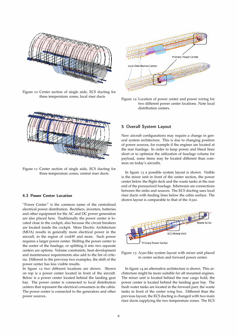
Figure 10: Center section of single aisle, ECS ducting forthree temperature zones, local riser ducts
Figure 11: Center section of single aisle, ECS ducting forthree temperature zones, central riser ducts
4.3 Power Center Location
“Power Center” is the common name of the centralizedelectrical power distribution. Rectifiers, inverters, batteriesand other equipment for the AC and DC power generationare also placed here. Traditionally the power center is lo-cated close to the cockpit, also because the circuit breakersare located inside the cockpit. More Electric Architecture(MOA) results in generally more electrical power in theaircraft, in the region of 100kW and more. Such powerrequires a larger power center. Shifting the power center tothe center of the fuselage, or splitting it into two separatecenters are options. Volume constraints, heat developmentand maintenance requirements also add to the list of crite-ria. Different to the previous two examples, the shift of thepower center has less visible results.In figure 12 two different locations are shown. Shownon top is a power center located in front of the aircraft.Below is a power center located behind the landing gearbay. The power center is connected to local distributioncenters that represent the electrical consumers in the cabin.The power center is connected to the generators and otherpower sources.
Figure 12: Location of power center and power wiring fortwo different power center locations. Note localdistribution centers.
5 Overall System Layout
New aircraft configurations may require a change in gen-eral system architecture. This is due to changing positionof power sources, for example if the engines are located atthe rear fuselage. In order to keep power and bleed linesshort or to optimize the utilization of fuselage volume forpayload, some items may be located different than com-mon on today’s aircrafts.
In figure 13 a possible system layout is shown. Visibleis the mixer unit in front of the center section, the powercenter below the flight deck and the waste tanks at the rearend of the pressurized fuselage. Inbetween are connectionsbetween the sinks and sources. The ECS ducting uses localriser ducts with feeding lines below the cabin surface. Theshown layout is comparable to that of the A320.
Figure 13: A320-like system layout with mixer unit placedin center section and forward power center.
In figure 14 an alternative architecture is shown. This ar-chitecture might be more suitable for aft mounted engines.The mixer unit is located behind the rear cargo hold, thepower center is located behind the landing gear bay. Thefresh water tanks are located in the forward part, the wastetanks in front of the center wing box. Different than theprevious layout, the ECS ducting is changed with two mainriser ducts supplying the two temperature zones. The ECS
6
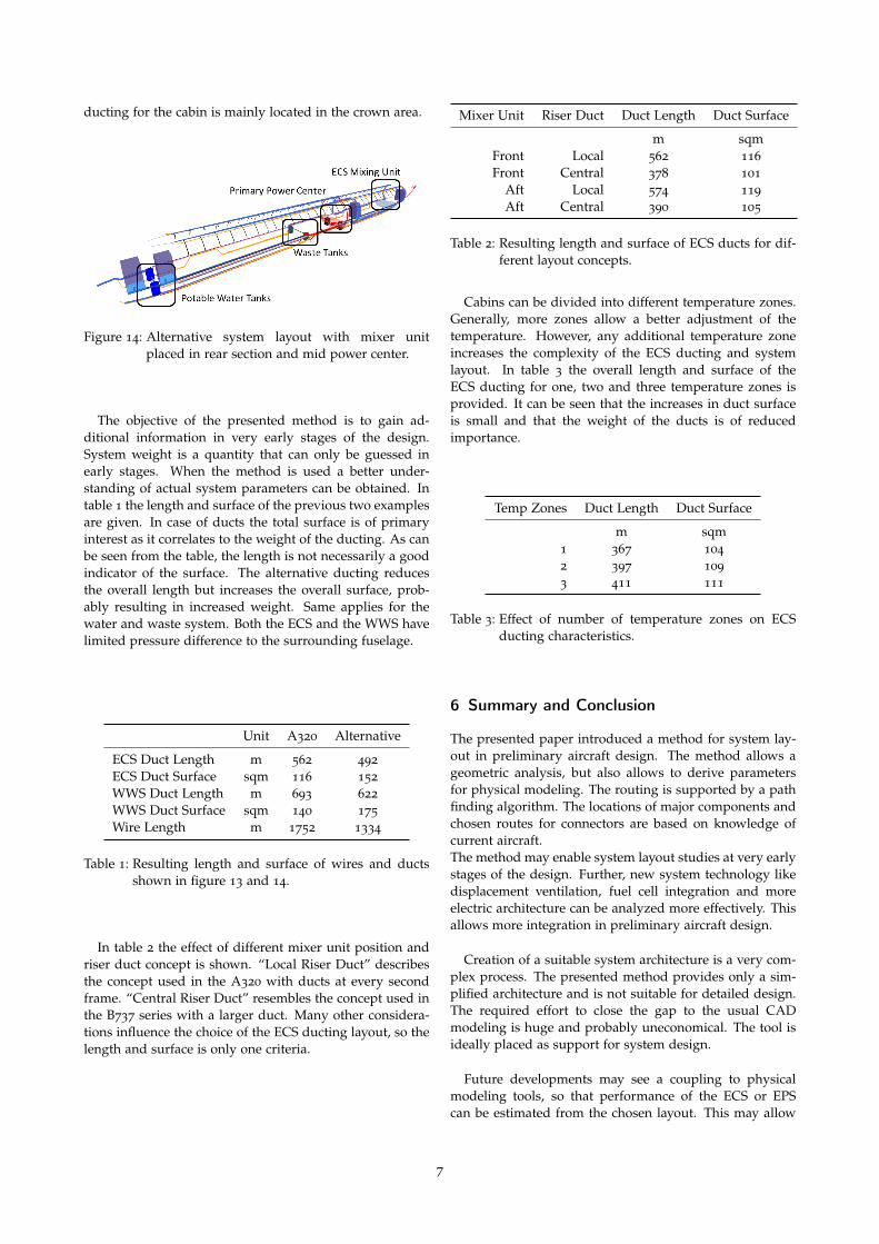
ducting for the cabin is mainly located in the crown area.
Figure 14: Alternative system layout with mixer unitplaced in rear section and mid power center.
The objective of the presented method is to gain ad-ditional information in very early stages of the design.System weight is a quantity that can only be guessed inearly stages. When the method is used a better under-standing of actual system parameters can be obtained. Intable 1 the length and surface of the previous two examplesare given. In case of ducts the total surface is of primaryinterest as it correlates to the weight of the ducting. As canbe seen from the table, the length is not necessarily a goodindicator of the surface. The alternative ducting reducesthe overall length but increases the overall surface, prob-ably resulting in increased weight. Same applies for thewater and waste system. Both the ECS and the WWS havelimited pressure difference to the surrounding fuselage.
Unit A320 Alternative
ECS Duct Length m 562 492
ECS Duct Surface sqm 116 152
WWS Duct Length m 693 622
WWS Duct Surface sqm 140 175
Wire Length m 1752 1334
Table 1: Resulting length and surface of wires and ductsshown in figure 13 and 14.
In table 2 the effect of different mixer unit position andriser duct concept is shown. “Local Riser Duct” describesthe concept used in the A320 with ducts at every secondframe. “Central Riser Duct” resembles the concept used inthe B737 series with a larger duct. Many other considera-tions influence the choice of the ECS ducting layout, so thelength and surface is only one criteria.
Mixer Unit Riser Duct Duct Length Duct Surface
m sqmFront Local 562 116
Front Central 378 101
Aft Local 574 119
Aft Central 390 105
Table 2: Resulting length and surface of ECS ducts for dif-ferent layout concepts.
Cabins can be divided into different temperature zones.Generally, more zones allow a better adjustment of thetemperature. However, any additional temperature zoneincreases the complexity of the ECS ducting and systemlayout. In table 3 the overall length and surface of theECS ducting for one, two and three temperature zones isprovided. It can be seen that the increases in duct surfaceis small and that the weight of the ducts is of reducedimportance.
Temp Zones Duct Length Duct Surface
m sqm1 367 104
2 397 109
3 411 111
Table 3: Effect of number of temperature zones on ECSducting characteristics.
6 Summary and Conclusion
The presented paper introduced a method for system lay-out in preliminary aircraft design. The method allows ageometric analysis, but also allows to derive parametersfor physical modeling. The routing is supported by a pathfinding algorithm. The locations of major components andchosen routes for connectors are based on knowledge ofcurrent aircraft.The method may enable system layout studies at very earlystages of the design. Further, new system technology likedisplacement ventilation, fuel cell integration and moreelectric architecture can be analyzed more effectively. Thisallows more integration in preliminary aircraft design.
Creation of a suitable system architecture is a very com-plex process. The presented method provides only a sim-plified architecture and is not suitable for detailed design.The required effort to close the gap to the usual CADmodeling is huge and probably uneconomical. The tool isideally placed as support for system design.
Future developments may see a coupling to physicalmodeling tools, so that performance of the ECS or EPScan be estimated from the chosen layout. This may allow
7
better weight and energy consumption estimations. Thementioned data exchange format CPACS represents a suit-able platform for such coupling of analysis tools.
References
[1] Airbus: Training Manual A319/320/321, ATA 21, AirCondioning System, General Familiarization. 1997
[2] Airbus Customer Services: A380 - Flight Deck andSystems Briefing for Pilots
[3] Boeing Commercial Airplanes: The Boeing 7E7 -System Overview. 7E7 Middle East Technical and Main-tenance Conference, 2004
[4] Carsten Koeppen: Methodik zur modellbasiertenPrognose von Flugzeugsystemparametern im Vorentwurfvon Verkehrsflugzeugen. Schriftenreihe Flugzeug-Systemtechnik, 2006
[5] D. Böhnke, B. Nagel, V. Gollnick: An Approachto Multi-Fidelity in Conceptual Aircraft Design in Dis-tributed Design Environments. 2011
[6] Dieter Scholz: Aircraft Systems - A Description of theA321. Lecture Notes, University of Applied SciencesHamburg, 2000
[7] Elwood Hunt, Don Reid, David Space, Fred Tilton:Commercial Airliner Environmental System. Aerospace
Medical Association, Annual Meeting, Anaheim May1995, 1995
[8] Hans-Jürgen Heinrich: Wasser- und Abwassersys-teme. Praxisseminar Luftfahrt - Vortrag an der HAWHamburg, 2004
[9] Hauke Lüdders, F. Kirchner, Frank Thielecke:SYSFUEL+ - Eine Bewertungsplattform für ein multifunk-tionales Brennstoffzellensystem auf Gesamtflugzeugebene.60. Deutscher Luft- und Raumfahrtkongress, 2011
[10] Jan Roskam: Aircraft Design Part IV: Layout Design ofLanding Gear and Systems. Roskam Aviation and Engi-neering Corporation, 1986
[11] Jörg Fuchte, Niclas Dzikus, Björn Nagel, Volker
Gollnick: Cabin Design for Minimum Boarding Time.60. Deutscher Luft- und Raumfahrtkongress, 2011
[12] Jörg Fuchte, Sergej Raskowski, Andreas Wick:Rapid Creation of CFD-Capable CAD-Models for CabinAir Ventilation Simulation. Workshop on Aircraft Sys-tem Technology 2011, 2011
[13] Jürgen Dollmayer: Methode zur Prognose des Ein-flusses von Flugzeugsystemen auf die Missionskraftstoff-masse. Schriftenreihe Flugzeug-Systemtechnik, 2007
[14] Tim Lammering, Echhard Anton, Kristoff Risse:Impact of System Integration on Fuel Efficiency in Prelim-inary Aircraft Design. Workshop on Aircraft SystemTechnology 2011, 2011
8