
CPX Terminal - Festo · 1.2.3 Use of the memory card 1−14 ... control signals to the connected...
110
Manual Electronics CPX Bus Node Type CPX−FB33 Type CPX−FB34 Network protocol PROFINET IO CPX Terminal Manual 548 760 en 0710NH [706 040]
Transcript of CPX Terminal - Festo · 1.2.3 Use of the memory card 1−14 ... control signals to the connected...
Manual Electronics
CPX Bus Node
Type CPX−FB33Type CPX−FB34
Network protocolPROFINET IO
CPX Terminal
Manual548 760en 0710NH[706 040]


Contents and general instructions
IFesto P.BE−CPX−PNIO−EN en 0710NH
Original de. . . . . . . . . . . . . . . . . . . . . . . . . . . . . . . . . . . . . . .
Edition en 0710NH. . . . . . . . . . . . . . . . . . . . . . . . . . . . . . . . .
Designation P.BE−CPX−PNIO−EN. . . . . . . . . . . . . . . . . . . . . . .
Order no. 548 760. . . . . . . . . . . . . . . . . . . . . . . . . . . . . . . . .
© (Festo AG�&�Co. KG, D�73726 Esslingen, Germany, 2007)Internet: http://www.festo.comE−Mail: [email protected]
The reproduction, distribution and utilization of this docu−ment as well as the comunication of its contents to otherswithout express authorization is prohibited. Offenders willbe held liable for the payment of damages. All rights re−served in the event of the grant of a patent, utility moduleor design.
Contents and general instructions
II Festo P.BE−CPX−PNIO−EN en 0710NH
PROFINET IO�® is a registered trade mark of Profibus International (PI)
PROFIBUS�® is a registered trade mark of Profibus International (PI)
SIMATIC�® is a registered trade name of Siemens AG
SPEEDCON�® is a registered trade name of PHOENIX CONTACT GmbH & Co. KG, 32825 Blomberg, Germany
TORX�® is a registered trade name of CAMCAR TEXTRON INC.,Rockford, Ill., USA

Contents and general instructions
IIIFesto P.BE−CPX−PNIO−EN en 0710NH
Contents
Intended use V . . . . . . . . . . . . . . . . . . . . . . . . . . . . . . . . . . . . . . . . . . . . . . . . . . . . . . . . . .
Target group� V . . . . . . . . . . . . . . . . . . . . . . . . . . . . . . . . . . . . . . . . . . . . . . . . . . . . . . . . . .
Service V . . . . . . . . . . . . . . . . . . . . . . . . . . . . . . . . . . . . . . . . . . . . . . . . . . . . . . . . . . . . . . .
Notes about the use of this manual VI . . . . . . . . . . . . . . . . . . . . . . . . . . . . . . . . . . . . . . . .
Important user instructions VIII . . . . . . . . . . . . . . . . . . . . . . . . . . . . . . . . . . . . . . . . . . . . . .
1. Installation 1−1 . . . . . . . . . . . . . . . . . . . . . . . . . . . . . . . . . . . . . . . . . . . . . . . . . . .
1.1 General instructions for installation 1−3 . . . . . . . . . . . . . . . . . . . . . . . . . . . . . . . .
1.2 Settings of the DIL switches on the bus node 1−7 . . . . . . . . . . . . . . . . . . . . . . . . .
1.2.1 Removing and fitting the cover over the DIL switches and memory�card1−7
1.2.2 Settingthe DIL switches 1−8 . . . . . . . . . . . . . . . . . . . . . . . . . . . . . . . . . . .
1.2.3 Use of the memory card 1−14 . . . . . . . . . . . . . . . . . . . . . . . . . . . . . . . . . .
1.3 Connecting to the network 1−16 . . . . . . . . . . . . . . . . . . . . . . . . . . . . . . . . . . . . . . . .
1.3.1 General information about PROFINET networks 1−16 . . . . . . . . . . . . . . .
1.3.2 Overview of connection technology and network cables 1−18 . . . . . . . .
1.3.3 Network interface of the CPX−FB33 1−20 . . . . . . . . . . . . . . . . . . . . . . . . .
1.3.4 Network interface of the CPX−FB34 1−21 . . . . . . . . . . . . . . . . . . . . . . . . .
1.4 Compliance with protection class IP65/IP67 1−22 . . . . . . . . . . . . . . . . . . . . . . . . .
1.5 Pin assignment of power supply 1−23 . . . . . . . . . . . . . . . . . . . . . . . . . . . . . . . . . . .
2. Commissioning 2−1 . . . . . . . . . . . . . . . . . . . . . . . . . . . . . . . . . . . . . . . . . . . . . . . .
2.1 Configuration 2−3 . . . . . . . . . . . . . . . . . . . . . . . . . . . . . . . . . . . . . . . . . . . . . . . . . .
2.1.1 General information 2−3 . . . . . . . . . . . . . . . . . . . . . . . . . . . . . . . . . . . . . .
2.1.2 Module overview 2−4 . . . . . . . . . . . . . . . . . . . . . . . . . . . . . . . . . . . . . . . .
2.1.3 Device master file (GSD) and symbol files 2−9 . . . . . . . . . . . . . . . . . . . .
2.1.4 CPX terminal configuration with Siemens STEP 7 2−10 . . . . . . . . . . . . . .
2.1.5 Configuration example 2−26 . . . . . . . . . . . . . . . . . . . . . . . . . . . . . . . . . . .
2.1.6 Procedure for replacing a bus node 2−28 . . . . . . . . . . . . . . . . . . . . . . . . .
2.1.7 Configuration in the Remote Controller operating mode 2−30 . . . . . . . .

Contents and general instructions
IV Festo P.BE−CPX−PNIO−EN en 0710NH
2.2 Parameterisation 2−32 . . . . . . . . . . . . . . . . . . . . . . . . . . . . . . . . . . . . . . . . . . . . . . .
2.2.1 Start parameterisation during switching on (system start) 2−32 . . . . . .
2.2.2 Parameterisation of the CPX terminal with Siemens STEP 7 2−34 . . . . . .
2.2.3 Parameterisation with the Handheld 2−38 . . . . . . . . . . . . . . . . . . . . . . . .
2.2.4 Application example for the parameterisation 2−39 . . . . . . . . . . . . . . . .
2.3 Check list for commissioning the CPX terminal 2−40 . . . . . . . . . . . . . . . . . . . . . . .
3. Diagnosis 3−1 . . . . . . . . . . . . . . . . . . . . . . . . . . . . . . . . . . . . . . . . . . . . . . . . . . . . .
3.1 Overview of diagnostic possibilities 3−3 . . . . . . . . . . . . . . . . . . . . . . . . . . . . . . . .
3.2 Diagnostics via LEDs 3−5 . . . . . . . . . . . . . . . . . . . . . . . . . . . . . . . . . . . . . . . . . . . .
3.2.1 Network error display LED NF / Connection status LED TP1, TP2 3−7 .
3.2.2 Fault displays of the LEDs for system diagnosis PS, PL, SF, M 3−8 . . . .
3.3 Diagnostics via status bits 3−11 . . . . . . . . . . . . . . . . . . . . . . . . . . . . . . . . . . . . . . . .
3.4 Diagnostics via the I/O diagnostic interface (STI) 3−12 . . . . . . . . . . . . . . . . . . . . .
3.5 Diagnostics via PROFINET 3−13 . . . . . . . . . . . . . . . . . . . . . . . . . . . . . . . . . . . . . . . .
3.5.1 Basic information 3−13 . . . . . . . . . . . . . . . . . . . . . . . . . . . . . . . . . . . . . . . .
3.5.2 Online diagnostics with Siemens STEP 7 3−16 . . . . . . . . . . . . . . . . . . . . .
3.5.3 User−specific diagnostics with Siemens STEP 7 3−18 . . . . . . . . . . . . . . . .
A. Technical appendix A−1 . . . . . . . . . . . . . . . . . . . . . . . . . . . . . . . . . . . . . . . . . . . . .
A.1 Technical specifications of bus node CPX−FB33 A−3 . . . . . . . . . . . . . . . . . . . . . . .
A.2 Technical specifications of bus node CPX−FB34 A−4 . . . . . . . . . . . . . . . . . . . . . . .
B. Index B−1 . . . . . . . . . . . . . . . . . . . . . . . . . . . . . . . . . . . . . . . . . . . . . . . . . . . . . . . . .

Contents and general instructions
VFesto P.BE−CPX−PNIO−EN en 0710NH
Intended use
The CPX−FB33 and CPX−FB34 bus nodes documented in thisdescription are only intended for use as participants(I/O�device) on PROFINET IO.
The CPX terminal must only be used as follows:
� as designated in industrial applications.
� in original condition without modification (only the con�versions or modifications described in the documentationsupplied with the product are permitted).
� in faultless technical condition.
The maximum values specified for pressures, temperatures,electrical data, torques etc. must be observed.
If additional commercially available components such assensors and actuators are connected, the specified limits forpressures, temperatures, electrical data, torques, etc. mustnot be exceeded.
Also observe the standards specified in the relevant chapters,as well as national and local laws and technical regulations.
Target group�
This manual is intended exclusively for technicians trained incontrol and automation technology who have experience ininstalling, commissioning, programming and diagnosingslaves on PROFINET.
Service
Please consult your local Festo Service agent if you have anytechnical problems.

Contents and general instructions
VI Festo P.BE−CPX−PNIO−EN en 0710NH
Notes about the use of this manual
This manual contains information about the followingmodules:
CPX Bus Node Typedesignation
Description Connections
CPX−FB33 Ethernet−based CPX bus nodefor PROFINET IO. PROFINET uses the Ethernetstandards and TCP/IP technology for communicationin an industrial environment.
Data transmission: IndustrialEthernet (based on IEEE 802.3),Switched Fast Ethernet,100�Mbit/s.
2x M12 D−coded female4−pole, according toIEC�61076−2−101 and IEC60130−9
CPX−FB34
100�Mbit/s.
Specifications, standardsrelating to PROFINET IO RT:� PROFINET Installation Guide� IEC 61158� IEC 61784
2 x Push−pull RJ45 copper,according to IEC PAS61076−3−117, IEC61076−3−106 and IEC 60603
Tab.�0/1: Bus node overview for PROFINET
Contents and general instructions
VIIFesto P.BE−CPX−PNIO−EN en 0710NH
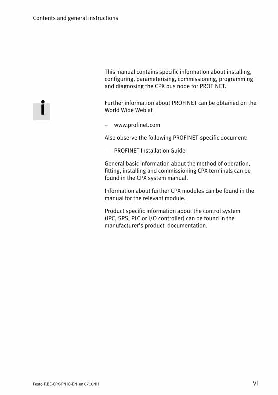
This manual contains specific information about installing,configuring, parameterising, commissioning, programmingand diagnosing the CPX bus node for PROFINET.
Further information about PROFINET can be obtained on theWorld Wide Web at
� www.profinet.com
Also observe the following PROFINET−specific document:
� PROFINET Installation Guide
General basic information about the method of operation,fitting, installing and commissioning CPX terminals can befound in the CPX system manual.
Information about further CPX modules can be found in themanual for the relevant module.
Product specific information about the control system(IPC,�SPS, PLC or I/O controller) can be found in the�manufacturer’s product� documentation.

Contents and general instructions
VIII Festo P.BE−CPX−PNIO−EN en 0710NH
Important user instructions
Danger categories
This manual contains instructions on the possible dangerswhich may occur if the product is not used correctly. Theseinstructions are marked (Warning, Caution, etc.), printed on ashaded background and marked additionally with a picto�gram. A distinction is made between the following dangerwarnings:
WarningThis means that failure to observe this instruction mayresult in serious personal injury or damage to property.
CautionThis means that failure to observe this instruction mayresult in personal injury or damage to property.
NoteThis means that failure to observe this instruction mayresult in damage to property.
The following pictogram marks passages in the text whichdescribe activities with electrostatically sensitive compo�nents.
Electrostatically sensitive components may be damaged ifthey are not handled correctly.

Contents and general instructions
IXFesto P.BE−CPX−PNIO−EN en 0710NH
Marking special information
The following pictograms mark passages in the textcontaining special information.
Pictograms
Information:Recommendations, tips and references to other sources ofinformation.
Accessories:Information on necessary or sensible accessories for theFesto product.
Environment:Information on environment−friendly use of Festo products.
Text markings
· The bullet indicates activities which may be carried out inany order.
1. Figures denote activities which must be carried out in thenumerical order specified.
� Hyphens indicate general activities.
Contents and general instructions
X Festo P.BE−CPX−PNIO−EN en 0710NH
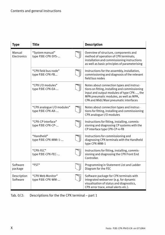
Type Title Description
ManualElectronics
�System manual"type�P.BE−CPX−SYS−...
Overview of structure, components andmethod of operation of CPX terminals;installation and commissioning instructionsas well as basic principles of parameterising
�CPX field bus node"type P.BE−CPX−FB...
Instructions for the assembly, installation,commissioning and diagnosis of the relevantfield bus nodes
�CPX I/O modules"type P.BE−CPX−EA−...
Notes about connection types and instruc�tions on fitting, installing and commissioninginput and output modules of type CPX−..., theMPA pneumatic modules, as well as MPA,CPA and Midi/Maxi pneumatic interfaces
�CPX analogue I/O modules"type P.BE−CPX−AX−...
Notes about connection types and instruc�tions for fitting, installing and commissioningCPX analogue I/O modules
�CPX−CP interface"type P.BE−CPX−CP−...
Instructions for fitting, installing, commis�sioning and diagnosing CP systems with theCP interface type CPX−CP−4−FB
�Handheld"type P.BE−CPX−MMI−1−...
Instructions for commissioning anddiagnosing CPX terminals with the Handheldtype�CPX−MMI−1
�CPX−FEC"type P.BE−CPX−FEC−...
Instructions for fitting, installing, commis�sioning and diagnosing the CPX Front EndController.
Softwarepackage
�FST" Programming in Statement List and LadderDiagram for the FEC
DescriptionSoftware
�CPX Web Monitor"type P.BE−CPX−WM−...
Software package for CPX terminals withintegrated webserver (e.g. for dynamicvisualisation of status and diagnostics,CPX�error trace, email alerts etc.).
Tab.�0/2: Descriptions for the the CPX terminal � part 1

Contents and general instructions
XIFesto P.BE−CPX−PNIO−EN en 0710NH
Type Title Description
ManualPneumatics
�Valve terminals withMPA�pneumatics"type P.BE−MPA−...
Instructions for fitting, installing, commission�ing, maintaining and converting the MPA pneu�matics (type 32)
�Valve terminals withCPA�pneumatics"type P.BE−CPA−...
Instructions for fitting, installing, commission�ing, maintaining and converting the CPA pneu�matics (type 12)
�Valve terminals withMidi/Maxi pneumatics"type P.BE−MIDI/MAXI−03−...
Instructions for fitting, installing, commission�ing, maintaining and converting the Midi/Maxipneumatics (type 03)
�Valve terminal withVTSA/ISO pneumatics"type P.BE−VTSA−44−...
Instructions for fitting, installing, commission�ing, maintaining and converting the VTSA/ISOpneumatics (type 44)
Tab.�0/3: Descriptions for the CPX terminal � part 2
Contents and general instructions
XII Festo P.BE−CPX−PNIO−EN en 0710NH
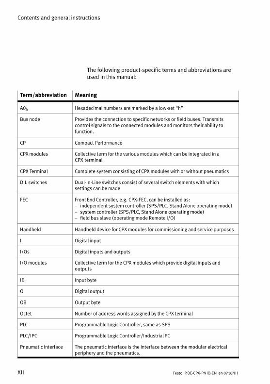
The following product−specific terms and abbreviations areused in this manual:
Term/abbreviation Meaning
A0h Hexadecimal numbers are marked by a low−set �h"
Bus node Provides the connection to specific networks or field buses. Transmitscontrol signals to the connected modules and monitors their ability tofunction.
CP Compact Performance
CPX modules Collective term for the various modules which can be integrated in aCPX�terminal
CPX Terminal Complete system consisting of CPX modules with or without pneumatics
DIL switches Dual−In−Line switches consist of several switch elements with whichsettings can be made
FEC Front End Controller, e.g. CPX−FEC, can be installed as:� independent system controller (SPS/PLC, Stand Alone operating mode)� system controller (SPS/PLC, Stand Alone operating mode)� field bus slave (operating mode Remote I/O)
Handheld Handheld device for CPX modules for commissioning and service purposes
I Digital input
I/Os Digital inputs and outputs
I/O modules Collective term for the CPX modules which provide digital inputs andoutputs
IB Input byte
O Digital output
OB Output byte
Octet Number of address words assigned by the CPX terminal
PLC Programmable Logic Controller, same as SPS
PLC/IPC Programmable Logic Controller�/�Industrial PC
Pneumatic interface The pneumatic interface is the interface between the modular electricalperiphery and the pneumatics.

Contents and general instructions
XIIIFesto P.BE−CPX−PNIO−EN en 0710NH
Term/abbreviation Meaning
PROFINET�IO�® Field bus system based on Industrial Ethernet for data exchange betweensystem controller (SPS/IPC) and field devices for the system controller(e.g. CPX−FEC; further information: www.profibus.com/pn,www.profibus.de)
PROFINET IO IRT PROFINET IO in the version with isochronous real−time protocol (typical cycle time: <�1�ms; typical application: drive controller)
PROFINET IO RT PROFINET IO in the version with real−time protocol (typical cycle time: 10�ms; typical application: production controller)
STI I/O diagnostic interface (system table interface)
Tab.�0/4: Specific terms and abbreviations

Contents and general instructions
XIV Festo P.BE−CPX−PNIO−EN en 0710NH

Installation
1−1Festo P.BE−CPX−PNIO−EN en 0710NH
Chapter 1
1. Installation
1−2 Festo P.BE−CPX−PNIO−EN en 0710NH
Contents
1. Installation 1−1 . . . . . . . . . . . . . . . . . . . . . . . . . . . . . . . . . . . . . . . . . . . . . . . . . . .
1.1 General instructions for installation 1−3 . . . . . . . . . . . . . . . . . . . . . . . . . . . . . . . .
1.2 Settings of the DIL switches on the bus node 1−7 . . . . . . . . . . . . . . . . . . . . . . . . .
1.2.1 Removing and fitting the cover over the DIL switches and memory�card 1−7 . . . . . . . . . . . . . . . . . . . . . . . . . . . . . . . . . . . . . . .
1.2.2 Settingthe DIL switches 1−8 . . . . . . . . . . . . . . . . . . . . . . . . . . . . . . . . . . .
1.2.3 Use of the memory card 1−14 . . . . . . . . . . . . . . . . . . . . . . . . . . . . . . . . . .
1.3 Connecting to the network 1−16 . . . . . . . . . . . . . . . . . . . . . . . . . . . . . . . . . . . . . . . .
1.3.1 General information about PROFINET networks 1−16 . . . . . . . . . . . . . . .
1.3.2 Overview of connection technology and network cables 1−18 . . . . . . . .
1.3.3 Network interface of the CPX−FB33 1−20 . . . . . . . . . . . . . . . . . . . . . . . . .
1.3.4 Network interface of the CPX−FB34 1−21 . . . . . . . . . . . . . . . . . . . . . . . . .
1.4 Compliance with protection class IP65/IP67 1−22 . . . . . . . . . . . . . . . . . . . . . . . . .
1.5 Pin assignment of power supply 1−23 . . . . . . . . . . . . . . . . . . . . . . . . . . . . . . . . . . .

1. Installation
1−3Festo P.BE−CPX−PNIO−EN en 0710NH
1.1 General instructions for installation
WarningBefore carrying out installation and maintenance work,switch off the following:
� compressed air supply
� the operating voltage supply for the electronics/sensors
� the load voltage supply for the outputs/valves.
You can thereby avoid:
� uncontrolled movements of loose tubing
� unexpected movements of the connected actuators
� undefined switching states of the electronic components.
CautionThe CPX bus node contains electrostatically sensitivecomponents.
· Therefore, do not touch any contacts.
· Observe the handling instructions for electrostaticallysensitive components.
You avoid malfunctions of and damage to the electronics bydoing so.
NoteUse a protective cap or blanking plug to seal unusedconnections. You will then comply with protection classIP65/IP67 (see section 1.4).
Information about fitting the CPX terminal can be found in theCPX system manual (P.BE−CPX−SYS−...).

1. Installation
1−4 Festo P.BE−CPX−PNIO−EN en 0710NH
Electrical connection and display elements
You will find the following connection and display elementson the CPX bus node for PROFINET:
1
2
3
4
CPX−FB33 CPX−FB34
2 2
3
4
2
55 1
1 Bus status−specific and CPX−specificLEDs
2 Network connection CPX−FB33: 2�x�M12 D−coded female
4−pinCPX−FB34: 2�x�Push−pull RJ45 copper
3 Cover for DIL switches andmemory�card
4 Service interface for the Handheld(V24)
5 Type plate with MAC−ID
Fig.�1/1: Connection and display elements on the CPX bus node
1. Installation
1−5Festo P.BE−CPX−PNIO−EN en 0710NH
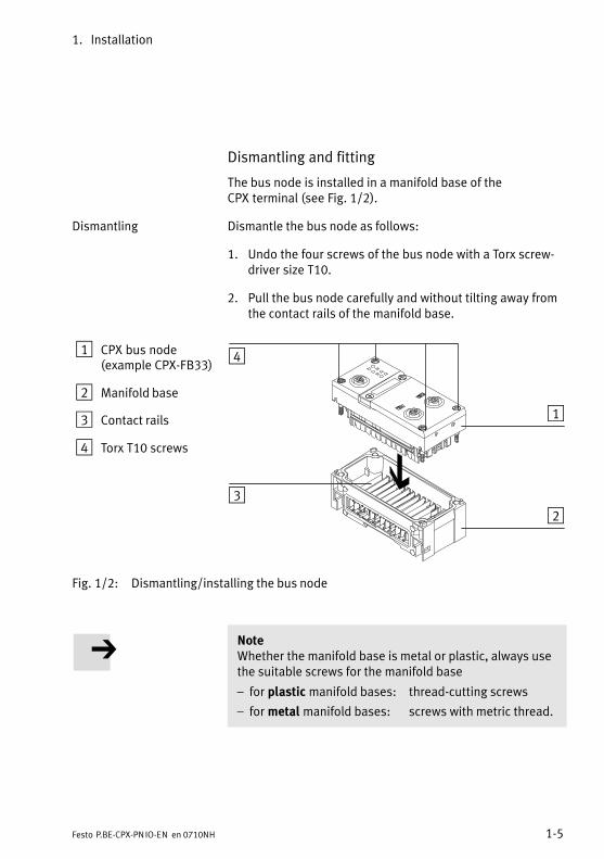
Dismantling and fitting
The bus node is installed in a manifold base of theCPX�terminal (see Fig.�1/2).
Dismantling Dismantle the bus node as follows:
1. Undo the four screws of the bus node with a Torx screw�driver size T10.
2. Pull the bus node carefully and without tilting away fromthe contact rails of the manifold base.
1 CPX bus node(example CPX−FB33)
2 Manifold base
3 Contact rails
4 Torx T10 screws
3
4
1
2
Fig.�1/2: Dismantling/installing the bus node
NoteWhether the manifold base is metal or plastic, always usethe suitable screws for the manifold base
� for plastic manifold bases: thread−cutting screws
� for metal manifold bases: screws with metric thread.
1. Installation
1−6 Festo P.BE−CPX−PNIO−EN en 0710NH
Both types of screws are enclosed respectively when orderingthe bus node as a single part.
Installation Install the bus node as follows:
1. Place the bus node in the manifold base. Make sure thatthe grooves with the power contact terminals on the bot�tom of the bus node are above the contact rails.
2. Push the bus node carefully and without tilting as far aspossible into the manifold base.
3. Tighten the screws at first only by hand. Place the screwsso that the self−cutting threads can be used.Tighten the screws with a Torx screwdriver size T10 with0.9 � 1.1 Nm.
1. Installation
1−7Festo P.BE−CPX−PNIO−EN en 0710NH
1.2 Settings of the DIL switches on the bus node
In order to make the settings for the CPX bus node and forchanging the memory card, you must first remove the coverover the DIL switches.
CautionThe CPX bus node contains electrostatically sensitivecomponents.
· Therefore, do not touch any contacts.
· Observe the handling instructions for electrostaticallysensitive components.
You avoid malfunctions of and damage to the electronics bydoing so.
1.2.1 Removing and fitting the cover over the DIL switches andmemory�card
You need a screwdriver in order to remove or fit the cover.
NoteObserve the following instructions when removing or fit�ting the cover:
· Disconnect the power supply before removing the cover.
· Make sure that the seal is seated correctly when fittingthe cover.
· Tighten the two fastening screws at first by hand andthen with max. 0.4 Nm.

1. Installation
1−8 Festo P.BE−CPX−PNIO−EN en 0710NH
1.2.2 Settingthe DIL switches
You can set the following parameters with the DIL switchesunder the cover (see Fig.�1/3):
� Bus node operating mode
� Diagnostic mode
Procedure
1. Switch off the power supply.
2. Remove the cover (see section 1.2.1).
3. Make the required settings (see Tab.�1/1 and Tab.�1/2).
4. Replace the cover (see section 1.2.1).
1 DIL switch 1:Bus node operatingmode
2 DIL switch 2 � only for operatingmode Remote I/O:Diagnostic mode 1
2
Fig.�1/3: Settings of the DIL switches on the bus node

1. Installation
1−9Festo P.BE−CPX−PNIO−EN en 0710NH
Setting the operating mode with DIL switch 1
You can set the operating mode of the bus node with switchelement 1 of DIL switch 1 (see Tab.�1/1):
� Operating mode Remote I/O
� Operating mode Remote Controller
Operating mode Setting DIL switch 1
Operating mode Remote I/OAll functions of the CPX terminal are controlled directly bythe PROFINET IO controller, a PLC or a superordinate SPS.In doing so, the bus node takes over the connection toPROFINET.
DIL 1.1: OFFDIL 1.2: OFF(factory setting)
Operating mode Remote ControllerRequirement: a CPX−FEC is an integral part of theCPX�terminal.The FEC integrated in the terminal controls all functions.The bus node takes over the connection to PROFINET.
DIL 1.1: ONDIL 1.2: OFF
Tab.�1/1: Setting the bus node operating mode with DIL switch 1
Remote I/O � Explanation of the operating mode
All functions of the CPX terminal are controlled directly by thePROFINET IO controller, a PLC or a superordinate SPS:
� control of the CPX valve terminal (also described asIO�Controller)
� data exchange between controller and modules
� parameterisation of the modules
� diagnostics.
1. Installation
1−10 Festo P.BE−CPX−PNIO−EN en 0710NH
Controller and CPX valve terminal communicate via PROFINET.In doing so, the bus node takes over the connection toPROFINET and processing the exchange of data:
� protocol implementation
� forwarding of incoming and outgoing data.
PROFINET RT (in bothoperating modes)
Thereby, the PROFINET Real−Time Protocol (RT) is used.
An FEC integrated in the CPX terminal works as a passivemodule, i.e. without controller. In this case, the FEC can beused for example for connection to other networks: The FECtakes over the forwarding of incoming and outgoing data andthus behaves like an I/O module.
Remote Controller � Explanation of the operating mode
A CPX−FEC integrated in the CPX terminal takes over thecontrol of the terminal (also described as IO Controller).
Requirements for this operating mode:
� A CPX−FEC is an integral part of the CPX terminal.
� For its part, the FEC is in the Remote Controller operatingmode. Ensure that the bus node and FEC DIL switches areset according to the operating mode. If necessary, set�tings at the program level must also be adjusted, e.g. inthe program side hardware configuration.
The bus node also takes over the connection to PROFINET inthis configuration:
� The FEC can communicate at the field bus level using an8−byte IO data field, e.g. with a PROFINET Controller.
� A superordinate controller can call up, e. g. statusinformation of the valve terminal using this interface andmatch or optimise the controller accordingly with othersystem parts.

1. Installation
1−11Festo P.BE−CPX−PNIO−EN en 0710NH
Addressing (in both operating modes)
Addressing the individual modules requires the superordi�nate controller: PROFINET or Industrial Ethernet uses module−oriented addressing, i.e. each module is addressed separ�ately (in contrast to block−oriented addressing of other fieldbus systems).
The controller uses the following for addressing:
� IP addresses
� field bus device names, in short Device Names.
For Remote Controller operating mode:
function of the DIL switch 2
The function of the DIL switch 2 depends on the setting of theDIL switch 1 or the set operating mode of the CPX terminal(see also Tab.�1/1): In the Remote Controller operating mode, DIL switch 2 isreserved for future expansions.

1. Installation
1−12 Festo P.BE−CPX−PNIO−EN en 0710NH
For Remote I/O operating mode:
setting the diagnostics mode with DIL switch 2
The function of this DIL switch depends on the set operatingmode of the CPX terminal (see also Tab.�1/1): The diagnostics mode is set in the Remote I/O operatingmode.
Diagnostic mode (Remote I/O operating mode)
SettingDIL switch 2
The I/O diagnostic interface and thestatus bits are switched off(+ 0 I/O bits)
2.1: OFF2.2: OFF(factorysetting)
The status bits are switched on(+ 8 I/O bits) 1)
2.1: OFF2.2: ON
The I/O diagnostic interface isswitched�on(+ 16 I/O bits) 1)
2.1: ON2.2: OFF
Reserved for future extensions 2.1: ON2.2: ON
1) Diagnostic mode status bit occupies 8 IO bits, IO diagnosticsinterface 16 IO bits.
Tab.�1/2: Setting the diagnostic mode with DIL switch 2(Remote I/O operating mode)

1. Installation
1−13Festo P.BE−CPX−PNIO−EN en 0710NH
NoteUse of the diagnostic mode (status bits or IO DiagnosticsInterface) occupies 8 or 16 IO bits and thus reduces thenumber of IO bits which are available for the modulecommunication. In this way, the number of addressablemodules is reduced in favour of additional status ordiagnostics information.
Take account of this fact for the planning of yourCPX�terminal.
The DIL switch settings for operating mode and diagnosticsmode must match the bus node selection in the context of aPLC hardware configuration (see section 2.1.4 and configur�ation example in Fig.�1/4).
1
2
3
1 In the Remote I/O operating mode with IO DiagnosticsInterface diagnostics mode, select a bus node module with
System Table Interface or STI mode identification from the
CPX field devices group.
2 In the Remote I/O operating mode with Status Bitsdiagnostics mode, select a bus node module with Statusmode identification from the CPX field devices group.
3 Select a bus node without mode identification in the
Remote I/O without diagnostics operating mode.
4 In the Remote Controller operating mode, select a bus
node module from the CPX Remote Controller field devices
group (separate group, not shown in the screenshot).
Fig.�1/4: Selection of the diagnost. mode in the PLC�software

1. Installation
1−14 Festo P.BE−CPX−PNIO−EN en 0710NH
1.2.3 Use of the memory card
The memory card is used as a carrier of configuration data,e.�g. of the field bus device name (PROFINET IO DeviceName). Thus, a bus node can be conveniently replaced.
NoteData stored on the card have priority over other configur�ation data which are stored, e.g. in the bus node memoryor in the controller system (see also section 2.2.1, sequence of the start parameterisation with memory card).
CautionRisk of malfunctions or damage.
Inserting or removing the memory card while the powersupply is switched on can result in malfunctions of ordamage to the memory card.
· Disconnect the power supply before you insert orremove the memory card.
Replacing thememory�card
The memory card is under a cover (see Fig.�1/1). You need ascrewdriver in order to remove or fit this cover.
Bus node replacement procedure
1. Switch off the power supply.
2. Remove the cover (observe section 1.2.1).
3. Remove the memory card from the bus node.
4. Replace the bus node.
5. Insert the memory card in the new bus node.
6. Replace the cover (observe section 1.2.1).
1. Installation
1−15Festo P.BE−CPX−PNIO−EN en 0710NH
7. Switch on the power supply.
8. Start the automation program if necessary.
9. The controller recognises the bus node using the devicename on the memory card and loads all required data.
Further information about using the memory card can befound in section 2.2.1.
1. Installation
1−16 Festo P.BE−CPX−PNIO−EN en 0710NH
1.3 Connecting to the network
1.3.1 General information about PROFINET networks
Irrespective of the network structure, the expansion of a�PROFINET segment for 100Base−TX must not exceed 100�m.A network can be subdivided into several segments usingswitches and routers. Thus, it is possible to structure thePROFINET network and realise greater network expansions.
NoteComponents with PROFINET interfaces must not be oper�ated in�networks where all connected network componentsare supplied with SELV/PELV power supplies or integratedpower supplies with similar protection.
Installation guidelines
The installation guidelines can be obtained via the PROFINETUser Organisation:
www.profinet.com
Observe the instructions there.
1. Installation
1−17Festo P.BE−CPX−PNIO−EN en 0710NH
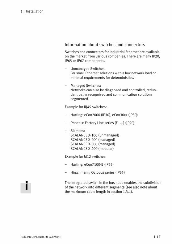
Information about switches and connectors
Switches and connectors for Industrial Ethernet are availableon the market from various companies. There are many IP20,IP65 or IP67 components.
� Unmanaged Switches: For small Ethernet solutions with a low network load orminimal requirements for deterministics.
� Managed Switches: Networks can also be diagnosed and controlled, redun�dant paths recognised and communication solutionssegmented.
Example for RJ45 switches:
� Harting: eCon2000 (IP30), eCon30xx (IP30)
� Phoenix: Factory Line series (FL ...) (IP20)
� Siemens: SCALANCE X−100 (unmanaged) SCALANCE X−200 (managed) SCALANCE X−300 (managed) SCALANCE X−400 (modular)
Example for M12 switches:
� Harting: eCon7100−B (IP65)
� Hirschmann: Octopus series (IP65)
The integrated switch in the bus node enables the subdivisionof the network into different segments (see also note aboutthe maximum cable length in section 1.3.1).

1. Installation
1−18 Festo P.BE−CPX−PNIO−EN en 0710NH
1.3.2 Overview of connection technology and network cables
NoteIf installation has not been carried out correctly and if highbaud rates are used, data transmission errors may occuras a result of signal reflections and attenuation. Causes of the transmission faults can be:
� incorrect screening/shield connection
� branches
� transmission over long distances
� unsuitable cables.
Observe the cable specifications. Refer to the manual ofyour controller for information about the required type ofcable.
NoteIf the CPX terminal is fitted onto the moving part of amachine, the network cable on the moving part must beprovided with strain relief. Please also observe the relevantregulations in EN�60204 part 1.
The CPX bus nodes for PROFINET support CrossoverDetection. Thus patch cables or crossover cables can beoptionally used.
1. Installation
1−19Festo P.BE−CPX−PNIO−EN en 0710NH
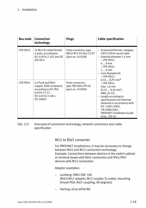
Bus node Connectiontechnology
Plugs Cable specification
CPX−FB33 2x M12 D−coded female4−pole, according toIEC�61076−2−101 and IEC60130−9
Festo connector, typeNECU−M−S−D12G4−C2−ET(part no. 543109)
� Screened Ethernet �categoryCAT5/CAT5e round cable
� External diameter 5.4�mm��CPX−FB33:6 ... 8 mm� CPX−FB34:5 ... 8 mm
� Core diameter/@:��CPX−FB33:0 14 0 75 mm2
CPX−FB34 2 x Push−pull RJ45copper, AIDA−compliant,according to IEC PAS61076−3−117,IEC�61076−3−106 +IEC�60603
Festo connector,type�FBS−RJ45−PP−GS(part no. 552000)
0,14 ... 0,75 mm2
� CPX−FB34:max. 1,6 mm(0,13 ... 0,36 mm2,AWG 26−22)
� Length according tospecifications for Ethernetnetworks in accordance withIEC 11801:2002,TIA 568B:2001,PROFINET Installation Guide(max. 100�m)
Tab.�1/3: Overview of connection technology, network connectors and cablespecification
M12 to RJ45 converter
For PROFINET installations, it may be necessary to changebetween RJ45 and M12 connection technology. Example: Connections between devices in the switch cabinetor terminal boxes with RJ45 connection and IP65/IP67devices with M12 connection.
Adapter examples:
� Lumberg: 0981 ENC 100(RJ45/M12 adapter, M12 coupler, D−coded, mountingthread PG9, RJ45 coupling, 90 degrees)
� Harting: eCon 6050−BA

1. Installation
1−20 Festo P.BE−CPX−PNIO−EN en 0710NH
1.3.3 Network interface of the CPX−FB33
There are two 4−pin, D−coded M12 sockets on the CPX−FB33for the network connection.
M12 socket Pin Signal Explanation
1
2
3
4
1234Case
TD+RD+TD�RD�Case
Send data+Receive data+Send data �Receive data �Screen�/�FE
Tab.�1/4: Pin assignment of the network interfaces of the CPX−FB33 (M12 4−pin)
Connection with plugs from Festo
Connect the CPX terminal to the network with Festo plugs(type NECU−M−S−D12G4−C2−ET (part no. 543�109).
In order to comply with protection class IP65/IP67:
� Use Festo connectors.
� Seal unused interfaces, see section 1.4.
1. Installation
1−21Festo P.BE−CPX−PNIO−EN en 0710NH
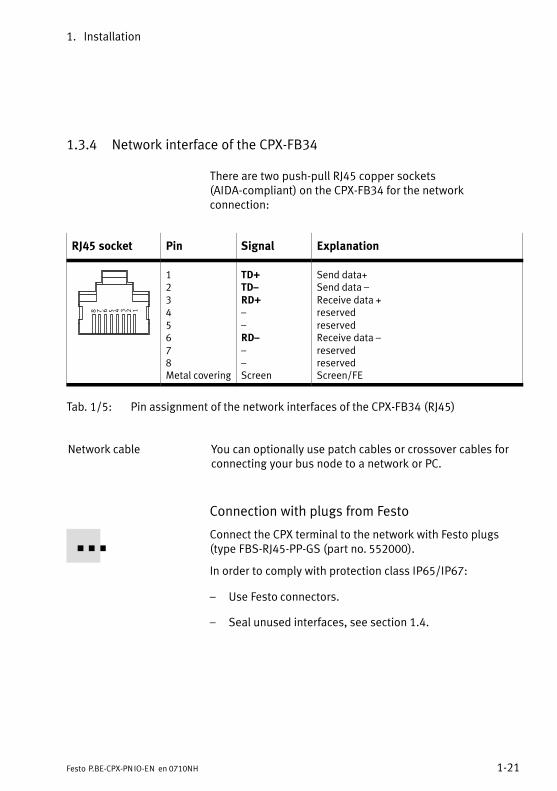
1.3.4 Network interface of the CPX−FB34
There are two push−pull RJ45 copper sockets(AIDA−compliant) on the CPX−FB34 for the networkconnection:
RJ45 socket Pin Signal Explanation
12345678
12345678Metal covering
TD+TD�RD+��RD���Screen
Send data+Send data �Receive data +reservedreservedReceive data �reservedreservedScreen�/�FE
Tab.�1/5: Pin assignment of the network interfaces of the CPX−FB34 (RJ45)
Network cable You can optionally use patch cables or crossover cables forconnecting your bus node to a network or PC.
Connection with plugs from Festo
Connect the CPX terminal to the network with Festo plugs(type FBS−RJ45−PP−GS (part no. 552�000).
In order to comply with protection class IP65/IP67:
� Use Festo connectors.
� Seal unused interfaces, see section 1.4.

1. Installation
1−22 Festo P.BE−CPX−PNIO−EN en 0710NH
1.4 Compliance with protection class IP65/IP67
In order to comply with protection class IP65/IP67, sealunused sockets with the appropriate connectors andprotective caps:
Connection Connection IP65/IP67 Cover IP65/IP67 1)
M12 D−coded female 4−pin(CPX−FB33: TP1, TP2)
Festo connector type� NECU−M−S−D12G4−C2−ET
(part no. 543�109)
Protective cap type ISK−M12(part no. 352�059)
Push−pull RJ45 Cu (CPX−FB34: TP1, TP2)
Festo connector type� FBS−RJ45−PP−GS
(part no. 552�000)
Cover type CPX−M−AK−C(part no. 548�753)
Service interface, M12 Connecting cable and plug forthe handheld
Protective cap type ISK−M12 2)
(part no. 352�059)
1) If connection is not used2) Included in scope of delivery
Tab.�1/6: Connections and covers for protection class IP65/IP67

1. Installation
1−23Festo P.BE−CPX−PN IO−EN en 0710NH
1.5 Pin assignment of power supply
Warning· Only use PELV circuits according to IEC/DIN EN 60204−1(Protective Extra−Low Voltage, PELV) for the powersupply. Also take into account the general requirements for PELVcircuits according to IEC/DIN EN 60204−1.
· Only use power packs which guarantee reliable electri�cal isolation of the operating voltage according to IEC/DIN EN 60204−1.
Due to the use of PELV power units, protection against elec�tric shock (protection against direct and indirect contact) isguaranteed in accordance with IEC/DIN EN 60204−1 (electri�cal equipment of machines, general requirements).
The current consumption of a CPX terminal depends on thenumber and type of integrated modules and components.
Read the information about the power supply as well as onthe earthing measures to be carried out in the �CPX systemmanual (P.BE−CPX−SYS−...).
1. Installation
1−24 Festo P.BE−CPX−PN IO−EN en 0710NH
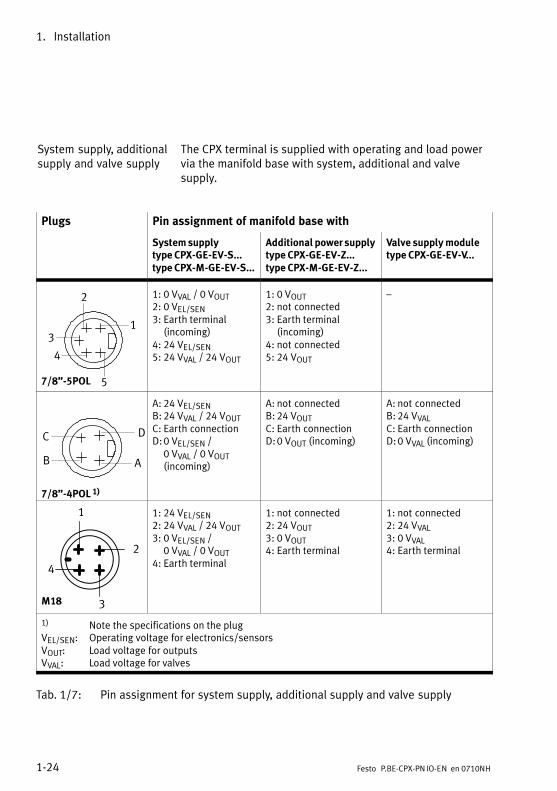
System supply, additionalsupply and valve supply
The CPX terminal is supplied with operating and load powervia the manifold base with system, additional and valvesupply.
Plugs Pin assignment of manifold base with
System supplytype CPX−GE−EV−S...type CPX−M−GE−EV−S...
Additional power supplytype CPX−GE−EV−Z...type CPX−M−GE−EV−Z...
Valve supply moduletype CPX−GE−EV−V...
7/8"−5POL
1
2
3
4
5
1: 0 VVAL / 0 VOUT2: 0 VEL/SEN3: Earth terminal
(incoming)4: 24 VEL/SEN5: 24 VVAL / 24 VOUT
1: 0 VOUT2: not connected3: Earth terminal
(incoming)4: not connected5: 24 VOUT
�
DC
B A
7/8"−4POL 1)
A: 24 VEL/SENB: 24 VVAL / 24 VOUTC: Earth connectionD:0 VEL/SEN /
0 VVAL / 0 VOUT (incoming)
A: not connectedB: 24 VOUTC: Earth connectionD:0 VOUT (incoming)
A: not connectedB: 24 VVALC: Earth connectionD:0 VVAL (incoming)
2
3
4
1
M18
1: 24 VEL/SEN2: 24 VVAL / 24 VOUT3: 0 VEL/SEN /
0 VVAL / 0 VOUT4: Earth terminal
1: not connected2: 24 VOUT3: 0 VOUT4: Earth terminal
1: not connected2: 24 VVAL3: 0 VVAL4: Earth terminal
1) Note the specifications on the plugVEL/SEN: Operating voltage for electronics/sensorsVOUT: Load voltage for outputsVVAL: Load voltage for valves
Tab.�1/7: Pin assignment for system supply, additional supply and valve supply

Commissioning
2−1Festo P.BE−CPX−PNIO−EN en 0710NH
Chapter 2

2. Commissioning
2−2 Festo P.BE−CPX−PNIO−EN en 0710NH
Contents
2. Commissioning 2−1 . . . . . . . . . . . . . . . . . . . . . . . . . . . . . . . . . . . . . . . . . . . . . . . .
2.1 Configuration 2−3 . . . . . . . . . . . . . . . . . . . . . . . . . . . . . . . . . . . . . . . . . . . . . . . . . .
2.1.1 General information 2−3 . . . . . . . . . . . . . . . . . . . . . . . . . . . . . . . . . . . . . .
2.1.2 Module overview 2−4 . . . . . . . . . . . . . . . . . . . . . . . . . . . . . . . . . . . . . . . .
2.1.3 Device master file (GSD) and symbol files 2−9 . . . . . . . . . . . . . . . . . . . .
2.1.4 CPX terminal configuration with Siemens STEP 7 2−10 . . . . . . . . . . . . . .
2.1.5 Configuration example 2−26 . . . . . . . . . . . . . . . . . . . . . . . . . . . . . . . . . . .
2.1.6 Procedure for replacing a bus node 2−28 . . . . . . . . . . . . . . . . . . . . . . . . .
2.1.7 Configuration in the Remote Controller operating mode 2−30 . . . . . . . .
2.2 Parameterisation 2−32 . . . . . . . . . . . . . . . . . . . . . . . . . . . . . . . . . . . . . . . . . . . . . . .
2.2.1 Start parameterisation during switching on (system start) 2−32 . . . . . .
2.2.2 Parameterisation of the CPX terminal with Siemens STEP 7 2−34 . . . . . .
2.2.3 Parameterisation with the Handheld 2−38 . . . . . . . . . . . . . . . . . . . . . . . .
2.2.4 Application example for the parameterisation 2−39 . . . . . . . . . . . . . . . .
2.3 Check list for commissioning the CPX terminal 2−40 . . . . . . . . . . . . . . . . . . . . . . .
2. Commissioning
2−3Festo P.BE−CPX−PNIO−EN en 0710NH
2.1 Configuration
2.1.1 General information
The configuration of the CPX bus node for PROFINET dependson the control system used.
The basic procedure and the required configuration data arepresented in the following pages.
NoteEvery module occupies a certain number of IO bits, bytesor words in the context of module communication. Thetotal number of available bytes per CPX terminal is limited.Please refer to Tab.�2/1 or Tab.�2/2 for the number ofIO�bytes occupied.Also, certain functions, e.g. the IO Diagnostics Interface(STI), reduce the�number of available IO bytes (in favour ofstatus or diagnostics functions).
Take account of this fact for the planning of yourCPX�terminal.
2. Commissioning
2−4 Festo P.BE−CPX−PNIO−EN en 0710NH
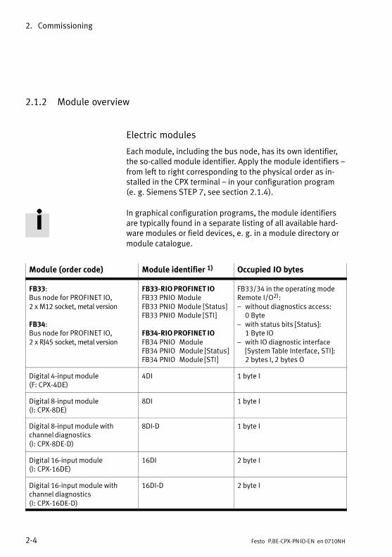
2.1.2 Module overview
Electric modules
Each module, including the bus node, has its own identifier,the so−called module identifier. Apply the�module identifiers �from left to right corresponding to the physical order as in�stalled in the CPX terminal � in your configuration program(e.�g. Siemens STEP 7, see section 2.1.4).
In graphical configuration programs, the module identifiersare typically found in a separate listing of all available hard�ware modules or field devices, e. g. in a module directory ormodule catalogue.
Module (order code) Module identifier 1) Occupied IO bytes
FB33:Bus node for PROFINET IO, 2 x M12 socket, metal version
FB34:Bus node for PROFINET IO, 2 x RJ45 socket, metal version
FB33−RIO PROFINET IOFB33�PNIO ModuleFB33�PNIO Module [Status]FB33�PNIO Module [STI]
FB34−RIO PROFINET IOFB34�PNIO �ModuleFB34�PNIO �Module [Status]FB34�PNIO �Module [STI]
FB33/34 in the operating mode Remote I/O�2)�:� without diagnostics access:
0�Byte� with status bits [Status]:
1�Byte IO� with IO diagnostic interface
[System Table Interface, STI]�:2�bytes I, 2�bytes�O
Digital 4−input module (F: CPX−4DE)
4DI 1 byte I
Digital 8−input module (I: CPX−8DE)
8DI 1 byte I
Digital 8−input module withchannel diagnostics(I: CPX−8DE−D)
8DI−D 1 byte I
Digital 16−input module (I: CPX−16DE)
16DI 2 byte I
Digital 16−input module withchannel diagnostics (I: CPX−16DE−D)
16DI−D 2 byte I

2. Commissioning
2−5Festo P.BE−CPX−PNIO−EN en 0710NH
Module (order code) Occupied IO bytesModule identifier 1)
Digital 4−output module (O: CPX−4DA)
4DO 1 byte O
Digital 8−output module (I: CPX−8DA)
8DO 1 byte O
Digital 8−output high currentoutput module (I: CPX−8DA−H)
8DO−H 1 byte O
Digital multi I/O module (Y: CPX−8DE−8DA)
8DI/8DO 1 byte I + 1 byte O
Analogue 2−input module (U:CPX−2AE−U/I)
2AI 2 words I
Analogue 4−input module (U:CPX−4AE−I)
4AI−I 4 words I
Analogue 4−input module(temperature module) (U:CPX−4AE−T)
4AI−T 2 words I/ 4 words I 3)
Analogue 4−input module(temperature module,thermocouple) (U:CPX−4AE−TC)
4AI−TC 4 words I
Analogue 2−output module (P:CPX−2AA−U/I)
2AO 2 words O
CP interface (CPI: � Byte I/� Byte O)
CPI Depends on the number of thelast used string:Per string:4 bytes I (32 inputs)4 bytes O (32 outputs)
Front−End−Controller CPX−FEC FEC Controller 8 bytes I, 8 bytes O
1) Module identifier in the handheld or in the hardware configuration of the programming softwareNote: In the handheld, the bus node is basically designated as �ProfiNet Remote I/O"
(independent from the operating mode).2) Number of occupied IO bytes in the Remote Controller operating mode: see Tab.�2/23) number of inputs which can be switched between 2 and 4
Tab.�2/1: Overview of electric CPX modules (bus node in Remote I/O operating mode)
2. Commissioning
2−6 Festo P.BE−CPX−PNIO−EN en 0710NH
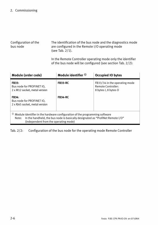
Configuration of thebus�node
The identification of the bus node and the diagnostics modeare configured in the Remote I/O operating mode(see�Tab.�2/1).
In the Remote Controller operating mode only the identifierof the bus node will be configured (see section Tab.�2/2):
Module (order code) Module identifier 1) Occupied IO bytes
FB33:Bus node for PROFINET IO, 2 x M12 socket, metal version
FB34:Bus node for PROFINET IO, 2 x RJ45 socket, metal version
FB33−RC
FB34−RC
FB33/34 in the operating modeRemote Controller:8 bytes I, 8 bytes O
1) Module identifier in the hardware configuration of the programming softwareNote: In the handheld, the bus node is basically designated as �ProfiNet Remote I/O"
(independent from the operating mode)
Tab.�2/2: Configuration of the bus node for the operating mode Remote Controller

2. Commissioning
2−7Festo P.BE−CPX−PNIO−EN en 0710NH
Pneumatic modules
The valves are configured according to the pneumaticinterface used:
� Valves of type 44/45 (VTSA/VTSA−F), type 03 (Midi/Maxi)or type 12 (CPA):When extensions are added to the valve side, only oneconfiguration is required for the pneumatic interface. Inthe pneumatic interface, the number of valve coils is setusing a DIL switch.
� Valves of type 32/33 (MPA/MPA−F pneumatic modules):From the technical point of view, the individual MPA pneu�matic modules each represent an electric module forcontrolling the attached valves. A configuration is re�quired for every pneumatic module of type MPA: Pneu�matic modules of type MPA1 each occupy 8−bit outputsindependently from how many valves are attached to thepneumatic module.Pneumatic modules of type MPA2 each occupy 8−bitoutputs, but only 4 bits are used.
Further information about the pneumatics can be found in thecorresponding pneumatics descriptions.

2. Commissioning
2−8 Festo P.BE−CPX−PNIO−EN en 0710NH
Module (order code) Module identifier 1) Occupied IO bytes
Pneumatic interface forVTSA�/�VTSA−F−Pneumatic (type�44/45)(VI: CPX type 44/45: 1−...V...)
ISO PlugIn ortype�44�/�type�45 2)
� 1 � 8 valve coils, 1�bytes O� 1 � 16 valve coils, 2�bytes O� 1 � 24 valve coils, 3�bytes O� 1 � 32 valve coils, 4�bytes O
Pneumatic interface for Midi/Maxivalves (type 03)(VI: CPX type 03: 1−...V...)
Type 03 � 1 � 8 valve coils, 1�bytes O� 1 � 16 valve coils, 2�bytes O� 1 � 24 valve coils, 3�bytes O� 1 � 26 valve coils, 4�bytes O
Pneumatic interface for CPA valves(type�12)(VI: CPX type 12: 1−...V...)
CPA10/14 � 1 � 8 valve coils, 1�bytes O� 1 � 16 valve coils, 2�bytes O� 1 � 22 valve coils, 3�bytes O
1) Module identifier in the Handheld2) Depending on the version of the Handheld
Tab.�2/3: Overview of CPX pneumatic interfaces
Module (order code) Module identifier 1) Occupied IO bytes
Pneumatic interface for MPA/MPA−Fvalves (type 32/33)
� �
MPA1 pneumatic module (type 32/33)without electrical isolation (VI: CPX type 32: 1−8V...)
MPA1S 1 byte O
MPA1 pneumatic module (type 32/33)with electrical isolation (VI: CPX type 32−G: 1−8V...)
MPA1G 1 byte O
MPA2 pneumatic module (type 32/33)without electrical isolation (VI: CPX type 32: 1−4V...)
MPA2S 1 byte O
MPA2 pneumatic module (type 32/33)with electrical isolation (VI: CPX type 32−G: 1−4V...)
MPA2G 1 byte O
1) Module identifier in the Handheld
Tab.�2/4: Overview of MPA pneumatic modules

2. Commissioning
2−9Festo P.BE−CPX−PN IO−EN en 0710NH
2.1.3 Device master file (GSD) and symbol files
A Device Master File (GSD) in XML format (GSDML) is neededfor the configuration and programming of the CPX terminalwith a programming device or PC. The GSDML contains all therequired information for the configuration and adjustment ofthe CPC terminal using configuration and programming soft�ware, e.g. Siemens STEP 7.
Source The current GSDML file for CPX terminals can be found on theFesto website at:
� www.festo.com/fieldbus
File download Upload the current GSDML file for CPX terminals to yourcontroller system:
� gsdml−v...−festo−cpx−...xml (dual language, English/German) for Siemens SIMATIC−compatible controllers andfor Siemens SIMATIC S7−300 and S7−400 with Firmwareversion 2.5.x or higher.
The installation of the GSDM file is explained on the followingpages.
Symbol files Symbol files for Festo CPX terminals for displaying the CPXterminal in your configuration software can be found at thewebsite address mentioned above. The integration of thesesymbol files is explained on the following pages.
Normal operatingstatus
Diagnostics case Specificoperating status
File: Pb_cpx_n.bmp File: Pb_cpx_d.bmp File: Pb_cpx_s.bmp
Tab.�2/5: Symbol files for the configuration andprogramming software

2. Commissioning
2−10 Festo P.BE−CPX−PN IO−EN en 0710NH
2.1.4 CPX terminal configuration with Siemens STEP 7
The following sections describe the basic configuration stepswith the SIEMENS STEP�7 configuration and programmingsoftware.
Other controller systems may require other settings or adifferent procedure.
The configuration examples shown in this chapter are basedon the use of a Siemens SPS SIMATIC S7−300 and theSiemens STEP�7 version 5.4 configuration and programmingsoftware. Operation of the STEP�7 software is assumed to beknown in the following.
NoteThere are different configuration programs available for aSiemens PLC. Observe the corresponding procedure foryour configuration program.
CautionDanger of malfunctions, damage or injuries to people
A valve terminal with defective configuration will also beput into operation. However, only the modules which havebeen correctly configured for type and position will beactivated.
Before commissioning, ensure that the connectedelements (e.g. actuators) do not perform any undesiredor uncontrollable movements.
If necessary, disconnect the load power supply andcompressed air supply.
See also section 2.3, Check list for commissioning theCPX�terminal.
2. Commissioning
2−11Festo P.BE−CPX−PN IO−EN en 0710NH
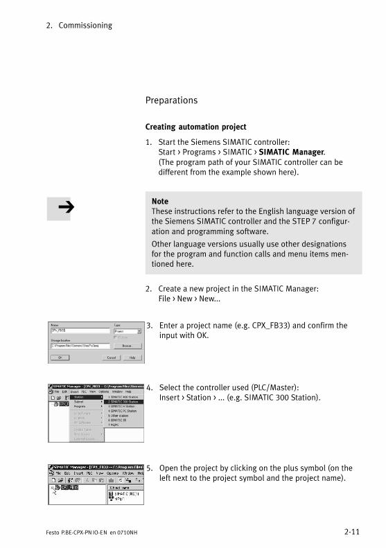
Preparations
Creating automation project
1. Start the Siemens SIMATIC controller: Start > Programs >�SIMATIC > SIMATIC Manager. (The program path of your SIMATIC controller can bedifferent from the example shown here).
NoteThese instructions refer to the English language version ofthe Siemens SIMATIC controller and the STEP�7 configur�ation and programming software.
Other language versions usually use other designationsfor the program and function calls and menu items men�tioned here.
2. Create a new project in the SIMATIC Manager: File > New >�New...
3. Enter a project name (e.g. CPX_FB33) and confirm theinput with OK.
4. Select the controller used (PLC/Master): Insert > Station >�... (e.g. SIMATIC 300 Station).
5. Open the project by clicking on the plus symbol (on theleft next to the project symbol and the project name).

2. Commissioning
2−12 Festo P.BE−CPX−PN IO−EN en 0710NH
Setting up the controller system (PLC/Master)
1. Click once on the station symbol (on the left next to thestation name) and afterwards double click on thehardware symbol in the �Object Name" column.The hardware configuration window HW Config(Station�Configuration) is displayed.
1
2. Open the hardware catalogue (Catalog View, 1 in the adjacent screenshot).
3. Select your controller system (PLC/Master) in the hard�ware catalogue (e.g. SIMATIC 300, 1 in Fig.�2/1):Click on the plus symbol in order to expand the selection.
4. Open the rack directory (e.g. RACK−300, 2 in Fig.�2/1).
5. Double click on the rack rail symbol (e.g.�RAIL, 2 inFig.�2/1). A child window (with rack rail symbol in theheader) opens in the left−hand area of the HW Configwindow ( 3 or 4 in Fig.�2/1).
The child window symbolises the rack rail (profile rail) ofyour controller system. You compile the individualelements of your controller in this child window and thusform the basis for your PROFINET automation system.

2. Commissioning
2−13Festo P.BE−CPX−PN IO−EN en 0710NH
1
3
24
1 Select controller system
2 Insert rack rail
3 Set up controller system in the rack rail window
Fig.�2/1: Setting up the controller system (PLC/Master) �inserting rack rail (Rail)
6. Add your CPU and a PROFINET IO system to the hardwareconfiguration: Drag the corresponding catalogueelements (symbols) into the Rack Rail window (���3 or 4 inFig.�2/1).
2. Commissioning
2−14 Festo P.BE−CPX−PN IO−EN en 0710NH
� Alternatively, you can also double click on the catalogueelement: Select the next free row (insert position, slot) inthe rack rail window before you make the double click.
� Row 1 (Slot 1) is reserved and cannot be used for theconfiguration.
Installing GSDML file
You install the GSDML file in the course of the following steps:
� gsdml−v...−festo−cpx−....xml
Source and remarks for the selection: see section 2.1.3.
1. Start the installation function from the STEP 7 menu:Options > Install GSD File ...
2. Update the hardware catalogue from the STEP 7 menu:Options > Update Catalog
All available CPX modules in the hardware catalogue aredisplayed under PROFINET IO > Additional Field Devices>�Valves > Festo CPX−Terminal. You can start the selectionand configuration of your modules.
2. Commissioning
2−15Festo P.BE−CPX−PN IO−EN en 0710NH
Hardware Configuration
Identifying the CPX terminal in the network (Device Name)
Use the �Node flashing test" function in order to identify yourCPX terminal in the network (the LEDs TP1 and TP2 flashsimultaneously). This function helps you with the allocationof the Device Name. You can also use this function to testwhether there is a logical data connection to the CPX terminal.
1. Start the PROFINET hardware configuration in yourconfiguration and programming software (e.g. HW Configin Siemens STEP�7).
2. Start the �Assign Device Name" function from the STEP 7menu: PLC > Ethernet > Assign Device Name.The �Assign Device Name" window is displayed.
3. If the CPX terminal is not displayed, start the refresh ofthe display: Click on �Update" for this.The network is searched and the network participantsfound are listed (under �Available Devices").
4. Select your found CPX terminal in the list (recognisablee.g. from the MAC−ID) and click on �Flashing on".The LEDs TP1 and TP2 of the bus node at the foundCPX�terminal flash for clear identification.
You can assign a device name to the CPX terminal in thenext step. This device name is also stored on the memorycard (provided it is inserted) of the bus node.
5. Enter a device name in the �Device Name" field (e.g. CPX or CPX−01) and confirm the entry by clicking on�Assign Name".
CPX terminal characteristics, station selection andIP�addressing
1. Start the PROFINET hardware configuration in yourconfiguration and programming software (e.g. HW Configin Siemens STEP�7).

2. Commissioning
2−16 Festo P.BE−CPX−PN IO−EN en 0710NH
1 2
3
Fig.�2/2: Station selection using Siemens STEP 7 � HW Config
2. If the hardware catalogue has not been opened: Click on the catalogue symbol (���1 in Fig.�2/2) or use thekeyboard combination [Ctrl] + [K].
The hardware catalogue is displayed.
2. Commissioning
2−17Festo P.BE−CPX−PN IO−EN en 0710NH
Selecting station 3. In the Hardware Catalogue, open the directory:
� �\PROFINET−IO\Additional Field Devices\Valves\Festo�CPX−Terminal" (English language version of the software)
or
� \PROFINET−IO\Weitere�Feldgeräte\Ventile\Festo�CPX−Terminal
If the directory �Valves\Festo CPX−Terminal" (Ventile\Festo CPX−Terminal) is not displayed, repeat the installa�tion of the device master file (GSDML, see section Instal�ling GSDML file).
4. Drag the �CPX" station symbol on to the bus line of thePROFINET IO system (���2 in Fig.�2/2).
The CPX terminal is displayed as a symbol (���3 � see alsoTab.�2/5) and connected to the bus of the PROFINET IOsystem.
Entering device name 5. Double click on the symbol of the CPX terminal 3.
The �Properties � CPX" window is displayed see Fig.�2/3).
You can assign or change a device name for the CPX ter�minal in the next step. This device name is also stored onthe memory card (provided it is inserted) of the bus node.
Using this device name, you can also directly �Address"the CPX terminal, e.g. in automation programs. Alterna�tively, you can also use the IP address or the MAC−ID foraddressing (information about IP addressing can befound in the following steps).
If you have allocated a device name in the course ofidentifying the CPX terminal, you can skip the next step.
2. Commissioning
2−18 Festo P.BE−CPX−PN IO−EN en 0710NH
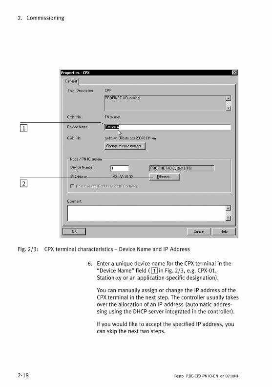
1
2
Fig.�2/3: CPX terminal characteristics � Device Name and IP Address
6. Enter a unique device name for the CPX terminal in the�Device Name" field ( 1 in Fig.�2/3, e.g. CPX−01,Station−xy or an application−specific designation).
You can manually assign or change the IP address of theCPX terminal in the next step. The controller usually takesover the allocation of an IP address (automatic addres�sing using the DHCP server integrated in the controller).
If you would like to accept the specified IP address, youcan skip the next two steps.
2. Commissioning
2−19Festo P.BE−CPX−PN IO−EN en 0710NH
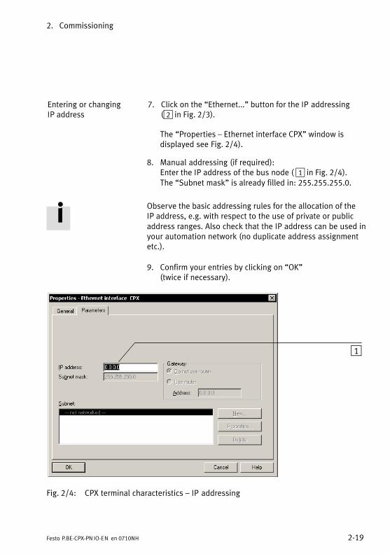
Entering or changingIP�address
7. Click on the �Ethernet..." button for the IP addressing(���2 in Fig.�2/3).
The �Properties � Ethernet interface CPX" window isdisplayed see Fig.�2/4).
8. Manual addressing (if required):Enter the IP address of the bus node (�1 in Fig.�2/4). The �Subnet mask" is already filled in: 255.255.255.0.
Observe the basic addressing rules for the allocation of theIP�address, e.g. with respect to the use of private or publicaddress ranges. Also check that the IP address can be used inyour automation network (no duplicate address assignmentetc.).
9. Confirm your entries by clicking on �OK" (twice if necessary).
1
Fig.�2/4: CPX terminal characteristics � IP addressing

2. Commissioning
2−20 Festo P.BE−CPX−PN IO−EN en 0710NH
CPX terminal configuration
Populate the configuration table (���2 in Fig.�2/5) with themodules of your CPX terminal. The CPX modules are dividedinto groups within the Hardware catalogue ( 3 ): Analog modules, Digital modules, Bus nodes, Pneumaticinterfaces, Pneumatic modules and Technology modules.
1
2
3 4
Fig.�2/5: CPX terminal configuration with Siemens STEP 7 � HW Config
1. Start the PROFINET hardware configuration in yourconfiguration and programming software (e.g. HW Config in Siemens STEP�7).

2. Commissioning
2−21Festo P.BE−CPX−PN IO−EN en 0710NH
2. If the hardware catalogue (���3 in Fig.�2/5) has not beenopened:Click on the catalogue symbol or use the keyboard com�bination [Ctrl] + [K].
The hardware catalogue is displayed.
Selecting CPX modules 3. In the hardware catalogue, open the directory:
� !\PROFINET−IO\Additional Field Devices\Valves\Festo�CPX−Terminal" (English language version of thesoftware)
or
� \PROFINET−IO\Weitere�Feldgeräte\Ventile\Festo�CPX−Terminal
If the directory �Valves\Festo CPX−Terminal" (Ventile\Festo�CPX−Terminal) is not displayed, repeat the installa�tion of the device master file (GSDML, see sectionInstalling GSDML file).
4. Click on the symbol of the CPX terminal to be configuredin the PROFINET hardware configuration (HW Config, 1 in Fig.�2/5).
The Configuration Table (���2 in Fig.�2/5) is displayed(underneath the schematic diagram of the PROFINET IOsystem; if necessary, enlarge this area of the HW Configwindow).
The configuration table represents your CPX terminal.
In the next step, you apply the individual modules of yourCPX terminal from the Hardware catalogue to the configur�ation table � according to the �physical" order, i.e. as in�stalled, from left to right. This area of the HW Config windowis therefore also designated as the Rack Rail window. Other designations: Profile Rail, Assembly Carrier or Rail.

2. Commissioning
2−22 Festo P.BE−CPX−PN IO−EN en 0710NH
5. Underneath the CPX station symbol CPX ( 3 ), i.e. in theCPX Field Devices group, in the Hardware catalogue, openthe required module subdirectory 4�.
6. Drag the catalogue elements or modules of your CPXterminal according to the �physical" order (as installed,from left to right) into the configuration table.
· Drag the first (left) module of your CPX terminal torow�1 of the configuration table (also designated asInsert Position 1 or Slot 1).
· Drag the next module to the respective next free rowof the configuration table.
Alternatively, you can also double click on the catalogueelement: Select the next free row in the rack rail windowbefore you make the double click.
I/O addresses and diagnostics addresses are assignedautomatically. You can change this assignment (see following sections �Changing I/O Addresses" and�Changing Diagnostics Addresses").
Selecting bus node · The following information refers to the previous point 6.This information only concerns the recording of busnodes in the configuration table of the CPX terminal.
· Various catalogue elements are available for theintegration of a FB33 or FB34 bus node.
The use of the catalogue elements depends on theoperating mode and diagnostics mode of the bus node.Check the settings of the DIL switches before selecting thecatalogue element (see section 1.2.2).
Ensure that the selected setting for operating mode anddiagnostics mode at the bus node matches the function ofthe catalogue element.
2. Commissioning
2−23Festo P.BE−CPX−PN IO−EN en 0710NH
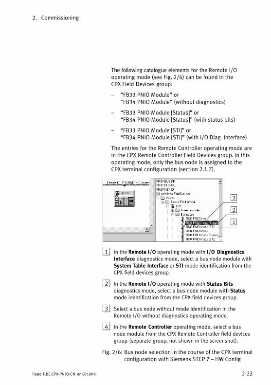
The following catalogue elements for the Remote I/Ooperating mode (see Fig.�2/6) can be found in theCPX�Field Devices group:
� �FB33 PNIO Module" or�FB34 PNIO Module" (without diagnostics)
� �FB33 PNIO Module [Status]" or�FB34 PNIO Module [Status]" (with status bits)
� �FB33 PNIO Module [STI]" or�FB34 PNIO Module [STI]" (with I/O Diag. Interface)
The entries for the Remote Controller operating mode arein the CPX Remote Controller Field Devices group. In thisoperating mode, only the bus node is assigned to theCPX�terminal configuration (section 2.1.7).
1
2
3
1 In the Remote I/O operating mode with I/O DiagnosticsInterface diagnostics mode, select a bus node module with
System Table Interface or STI mode identification from the
CPX field devices group.
2 In the Remote I/O operating mode with Status Bitsdiagnostics mode, select a bus node module with Statusmode identification from the CPX field devices group.
3 Select a bus node without mode identification in the
Remote I/O without diagnostics operating mode.
4 In the Remote Controller operating mode, select a bus
node module from the CPX Remote Controller field devices
group (separate group, not shown in the screenshot).
Fig.�2/6: Bus node selection in the course of the CPX terminalconfiguration with Siemens STEP 7 � HW Config

2. Commissioning
2−24 Festo P.BE−CPX−PN IO−EN en 0710NH
Further information about operating mode and diagnosticsmode:
� section 1.2.2, Setting the DIL switches
� section 3.1, Overview of diagnostics options
Changing I/O addresses 1. Double click on the module name in the configurationtable.
The �Properties ..." window is displayed.
2. Select the �Addresses" tab.
3. Change the �start address of the inputs or outputs.
4. Confirm the entry with �OK".
The modified address is displayed in the configurationtable.
Changing diagnosticsaddress
The diagnostics address is automatically assigned by theSiemens STEP 7 configuration and programming software �HW Config. A change is rarely required.
1. Double click on row 0 of the configuration table.
The �Properties � CPX" window is displayed see Fig.�2/7.
Fig.�2/7: Changing the diagnostics address with SiemensSTEP� 7 � HW Config

2. Commissioning
2−25Festo P.BE−CPX−PN IO−EN en 0710NH
2. Select the �Addresses" tab.
3. Enter the desired �Diagnostics Address".
(The available address range depends on the controllerused � see manufacturer documentation).
4. Confirm the entry with �OK".
The modified address is displayed in the configurationtable.
Further information about diagnostics:
� section 3.5, Diagnostics via PROFINET.
2. Commissioning
2−26 Festo P.BE−CPX−PNIO−EN en 0710NH
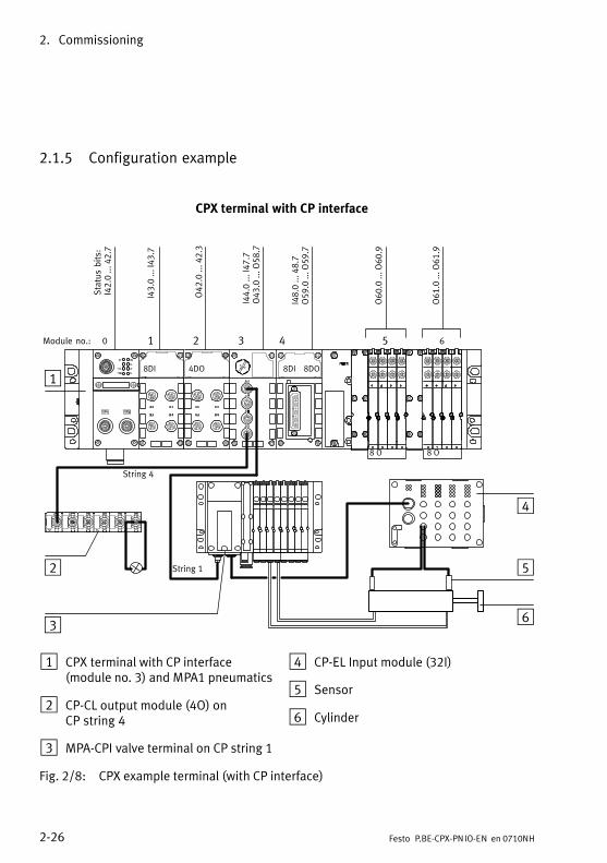
2.1.5 Configuration example
CPX terminal with CP interface
1 2 3 4 5 6Module no.: 0
8 O 8 O
1
2
3
8DI 4DO 8DI 8DO
Status bits:
I42.0 ... 4
2.7
I43.0 ... I43.7
O42.0 ... 4
2.3
I44.0 ... I47.7
O43.0 ... O
58.7
I48.0 ... 4
8.7
O59.0 ... O
59.7
O60.0 ... O
60.9
O61.0 ... O
61.9
4
5
6
String 4
String 1
1 CPX terminal with CP interface (module no. 3) and MPA1 pneumatics
2 CP−CL output module (4O) onCP�string�4
3 MPA−CPI valve terminal on CP string 1
4 CP−EL Input module (32��I)
5 Sensor
6 Cylinder
Fig.�2/8: CPX example terminal (with CP interface)

2. Commissioning
2−27Festo P.BE−CPX−PNIO−EN en 0710NH
In the example, the CP interface occupies 4 input bytes and16 output bytes (32 occupied inputs on string 1, 128 occu�pied outputs on strings 1 � 4; further information can befound in the CPX−CP Interface description P.BE−CPX−CP−...).
Moduleno.
Module Inputaddress
Outputaddress
0 Bus node (DIL switch setting and configuration with status bits)(FB33 PNIO Module Status)
42 �
1 Digital 8−input module(I: CPX−8DE)
43 �
2 Digital 4−output module(O: CPX−4DA)
� 42
3 CP interface with assignment of 4 input bytes and 16 outputbytes(CPI:�4 bytes I/16 bytes O)
44 � 47 43 � 58
4 Digital multi I/O module(Y: CPX−8DE−8DA)
48 59
� MPA pneumatic interface 1)
(type VMPA−FB−EPL−...)� �
5 MPA1 pneumatic module(VI: CPX type 32: 1−8V...)
� 60
6 MPA1 pneumatic module(VI: CPX type 32: 1−8V...)
� 61
1) Passive module
Tab.�2/6: Configuration and addressing for CPX example terminal (addresses usedfrom input/output word 42)

2. Commissioning
2−28 Festo P.BE−CPX−PNIO−EN en 0710NH
2.1.6 Procedure for replacing a bus node
Easy replacement using memory card
The memory card is used as a carrier of configuration data,e.�g. of the field bus device name (PROFINET IO DeviceName). Thus, a bus node can be conveniently replaced.
CautionRisk of malfunctions or damage.
Inserting or removing the memory card while the powersupply is switched on can result in malfunctions of ordamage to the memory card.
· Disconnect the power supply before you insert orremove the memory card.
Replacing thememory�card
The memory card is under a cover (see Fig.�1/1). You need ascrewdriver in order to remove or fit this cover.
Procedure
1. Switch off the power supply.
2. Remove the cover (observe section 1.2.1).
3. Remove the memory card from the bus node.
4. Replace the bus node (Installation/Dismantling: see section 1.1).
5. Insert the memory card in the new bus node.
6. Replace the cover (observe section 1.2.1).
7. Switch on the power supply.
8. Start the automation program if necessary.
9. The controller recognises the bus node using the devicename on the memory card and loads all required data.
2. Commissioning
2−29Festo P.BE−CPX−PNIO−EN en 0710NH
Replacement without memory card
Procedure
1. Switch off the power supply.
2. Replace the bus node (Installation/Dismantling: see section 1.1).
3. Switch on the power supply.
4. Start your configuration and programming software (e.�g. Siemens STEP�7).
5. Perform a new configuration (hardware configuration, inSTEP�7 using HW Config).
6. The controller loads all required data into the bus node.
2. Commissioning
2−30 Festo P.BE−CPX−PNIO−EN en 0710NH
2.1.7 Configuration in the Remote Controller operating mode
If there is an FEC in your CPX terminal, you can operate thebus node in the Remote Controller operating mode. The busnode then occupies 8 input bytes and 8 output bytes. Theseare available for the control program in the FEC and to thePROFINET Master.
Configuration of the busnode Remote Controlleroperating mode
1. Ensure that DIL switch 1 of the bus node is in theRemote Controller position (see section 1.2.2, Tab.�1/1).
2. Ensure that DIL switch 2 is in the ON position (reservedfor future expansions, see Tab.�1/2).
3. Start your configuration and programming software, e.g. Siemens STEP 7.
4. Open the hardware configuration, here: HW Config.
5. If you change an existing configuration: If necessary,remove the existing bus nodes and all other (subordi�nate) modules from this CPX terminal configuration.
6. Perform the bus node selection (station selection) withthe CPX remote controller station type (see section2.1.4 and 1 in Fig.�2/9).
The bus node is thus configured as Remote Controller.

2. Commissioning
2−31Festo P.BE−CPX−PNIO−EN en 0710NH
12
Fig.�2/9: Bus node configuration in the Remote Controller operating mode with SiemensSTEP 7 � HW Config
2. Commissioning
2−32 Festo P.BE−CPX−PN IO−EN en 0710NH
2.2 Parameterisation
You can set the reaction of the CPX terminal individually byparameterisation. The following parameterisation variants aredistinguished:
� System parameterisation, e.�g. deactivating errormessages etc.
� Parameterising the diagnostics memory
� Module parameterisation (module−specific and channel−specific), e.�g. module monitoring, settings for errors,adjustment of debounce times for the inputs etc.
A detailed description of the individual parameters as well asbasic information about application can be found in the CPXsystem manual (P.BE−CPX−SYS−...).
Parameter lists for the various CPX modules can be found inthe corresponding manuals for the modules (P.BE−CPX−EA−...,P.BE−CPX−AX−..., P.BE−CPX−CP−... etc.).
2.2.1 Start parameterisation during switching on (system start)
The parameterisation during system start of the CPX terminalis�initially dependent on the setting of the system start para�meter. This parameter specifies whether the start parameter�isation will be loaded from the PROFINET I/O Controller orfrom the CPX bus node. Details can be found in Fig.�2/10 andthe following explanations.
NoteThe start parameter set is loaded again (according to therules described above) after every interruption of thenetwork connection.
2. Commissioning
2−33Festo P.BE−CPX−PN IO−EN en 0710NH
2
PLC/IPC PROFINET
I/O Controller
1
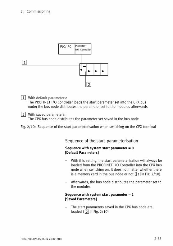
1 With default parameters:The PROFINET I/O Controller loads the start parameter set into the CPX busnode; the bus node distributes the parameter set to the modules afterwards
2 With saved parameters:The CPX bus node distributes the parameter set saved in the bus node
Fig.�2/10: Sequence of the start parameterisation when switching on the CPX terminal
Sequence of the start parameterisation
Sequence with system start parameter = 0 [Default Parameters]
� With this setting, the start parameterisation will always beloaded from the PROFINET I/O Controller into the CPX busnode when switching on. It does not matter whether thereis a memory card in the bus node or not (�1 in Fig.�2/10).
� Afterwards, the bus node distributes the parameter set tothe modules.
Sequence with system start parameter = 1 [Saved Parameters]
� The start parameters saved in the CPX bus node areloaded (�2 in Fig.�2/10).

2. Commissioning
2−34 Festo P.BE−CPX−PN IO−EN en 0710NH
2.2.2 Parameterisation of the CPX terminal with Siemens STEP 7
Setting system parameters
1. Start the PROFINET hardware configuration in yourconfiguration and programming software (e.�g. HW Configin Siemens STEP�7).
1
2 3 4
Fig.�2/11: Setting system parameters with Siemens STEP 7

2. Commissioning
2−35Festo P.BE−CPX−PN IO−EN en 0710NH
2. Mark the symbol of the CPX terminal on the PROFINET IOsystem (see 1 Fig.�2/11). The configuration table nowshows the configuration of the CPX terminal.
3. Double click on line 0 of the configuration table 2. The �Properties � CPX" dialogue window is displayed.
4. Select the �Parameter" (parameterisation) tab 3. The list with the parameters and the currently activevalues will be shown.
5. Click on the parameter value which you wish to modify. A list with the possible values will be opened 4.
6. Modify the parameter by clicking on the desired value.
7. Confirm the change afterwards.
Possibilities for parameterising the diagnosticsmemory mode
� �Save the first 40 entries" The first 40 diagnostic messages are saved, but thereafterno further messages are saved.
� �Save the last 40 entries" Continuous saving of all incoming diagnostics messages.After the 40th. message, the oldest message will be over�written.
� �Entries remanent on Power On � Active" The entries in the error memory are retained duringPower OFF/ON.
� �Entries remanent on Power On � Inactive" The entries in the error memory are cleared duringPower�OFF/ON.
2. Commissioning
2−36 Festo P.BE−CPX−PN IO−EN en 0710NH
NoteSystem parameters monitoring SCS/SCO/SCV, VOUT/VAL*)
The diagnostic messages regarding short−circuit/overloadand undervoltage can be suppressed for the completeCPX�terminal using system parameter monitoring(function�no. 4401).
The settings made separately for each module with theCPX module parameter monitoring are not affected by thesetting of the system parameter monitoring.
Further information about parameterisation can be foundin the CPX system manual (P.BE−CPX−SYS−...) in appendix B.
*) SCS Monitoring short/circuit overload � sensor supplySCO Monitoring short/circuit overload � outputsSCV Monitoring short/circuit overload � valves
VOUT/VAL Monitoring undervoltage � outputs/valves
2. Commissioning
2−37Festo P.BE−CPX−PN IO−EN en 0710NH
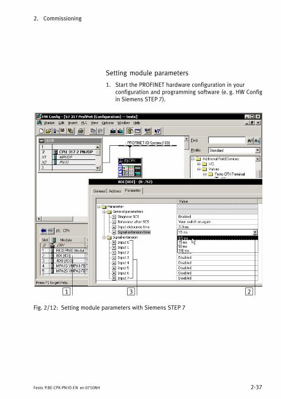
Setting module parameters
1. Start the PROFINET hardware configuration in yourconfiguration and programming software (e.�g. HW Configin Siemens STEP�7).
1 23
Fig.�2/12: Setting module parameters with Siemens STEP 7

2. Commissioning
2−38 Festo P.BE−CPX−PN IO−EN en 0710NH
2. Double click in the configuration table on the descriptionof the module you would like to parameterise (���1 in Fig.�2/12). The �Properties ..." dialogue window isdisplayed.
3. Click on the parameter value which you wish to modify. A list with the possible values will be opened 2.
4. Modify the parameter by clicking on the desired value.
5. Confirm the change afterwards.
NoteModule parameters can refer to:
� properties of the complete module
� properties of an individual channel of a module.
2.2.3 Parameterisation with the Handheld
The handheld provides menu guided access to theparameterisation of the CPX terminal without configurationsoftware.
If the handheld has write access to the parameters, youcannot parameterise the following parameters via the bus:
� System parameters
� Module parameters
Diagnostics memory parameters can also be parameterisedwhile the handheld is is use.
Information about operating the handheld can be found in themanual for the handheld P.BE−CPX−MMI−1−...
2. Commissioning
2−39Festo P.BE−CPX−PN IO−EN en 0710NH
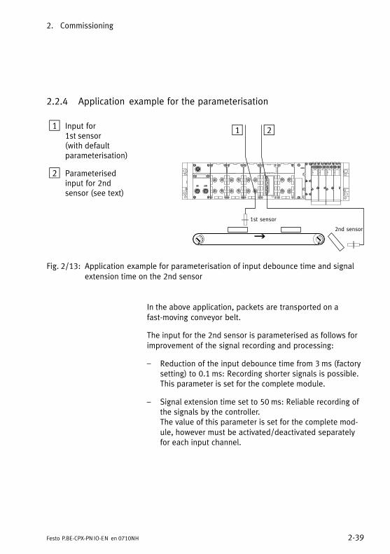
2.2.4 Application example for the parameterisation
1 Input for1st�sensor(with�defaultparameterisation)
2 Parameterisedinput for 2ndsensor (see text)
Î ÎÎ
21
1st sensor
2nd sensor
Fig.�2/13: Application example for parameterisation of input debounce time and signalextension time on the 2nd sensor
In the above application, packets are transported on afast−moving conveyor belt.
The input for the 2nd sensor is parameterised as follows forimprovement of the signal recording and processing:
� Reduction of the input debounce time from 3�ms (factorysetting) to 0.1�ms: Recording shorter signals is possible.This parameter is set for the complete module.
� Signal extension time set to 50�ms: Reliable recording ofthe signals by the controller.The value of this parameter is set for the complete mod�ule, however must be activated/deactivated separatelyfor each input channel.

2. Commissioning
2−40 Festo P.BE−CPX−PNIO−EN en 0710NH
2.3 Check list for commissioning the CPX terminal
Providing the safety concept of your machine/systempermits, commission the CPX terminal with both operatingvoltages � but without compressed air. You can then test theCPX terminal without triggering undesired reactions.
NotePlease observe the general commissioning instructionsin the CPX system manual and in the manual of yourcontroller.
CautionThe CPX terminal with bus node for PROFINET also startswith incomplete configuration.
· Check the configuration and address assignment of theI/Os on the CPX terminal. In order to do this, you can, ifnecessary, force the I/Os (see CPX system manualP.BE−CPX−SYS−...).
· An incomplete configuration will be displayed with thediagnostics LED of the controller and in the onlinediagnostics of your configuration software.
Procedure
· Check the DIL switch settings and the network configur�ation before using and replacing CPX terminals.
· Ensure that the desired start parameterisation of theCPX�terminal will be made after a network interruption.This ensures that if the CPX terminal is replaced, the newterminal will also be operated with the desired parametersettings (see also start parameterisation in section 2.2.1).
· Use spot checks if necessary to check the parameterisa�tion, e.g. with the configuration program or with theHandheld.
Diagnosis
3−1Festo P.BE−CPX−PNIO−EN en 0710NH
Chapter 3

3. Diagnosis
3−2 Festo P.BE−CPX−PNIO−EN en 0710NH
Contents
3. Diagnosis 3−1 . . . . . . . . . . . . . . . . . . . . . . . . . . . . . . . . . . . . . . . . . . . . . . . . . . . . .
3.1 Overview of diagnostic possibilities 3−3 . . . . . . . . . . . . . . . . . . . . . . . . . . . . . . . .
3.2 Diagnostics via LEDs 3−5 . . . . . . . . . . . . . . . . . . . . . . . . . . . . . . . . . . . . . . . . . . . .
3.2.1 Network error display LED NF / Connection status LED TP1, TP2 3−7 . . . . . . . . . . . . . . . . . . . . . . . . . . . .
3.2.2 Fault displays of the LEDs for system diagnosis PS, PL, SF, M 3−8 . . . .
3.3 Diagnostics via status bits 3−11 . . . . . . . . . . . . . . . . . . . . . . . . . . . . . . . . . . . . . . . .
3.4 Diagnostics via the I/O diagnostic interface (STI) 3−12 . . . . . . . . . . . . . . . . . . . . .
3.5 Diagnostics via PROFINET 3−13 . . . . . . . . . . . . . . . . . . . . . . . . . . . . . . . . . . . . . . . .
3.5.1 Basic information 3−13 . . . . . . . . . . . . . . . . . . . . . . . . . . . . . . . . . . . . . . . .
3.5.2 Online diagnostics with Siemens STEP 7 3−16 . . . . . . . . . . . . . . . . . . . . .
3.5.3 User−specific diagnostics with Siemens STEP 7 3−18 . . . . . . . . . . . . . . . .

3. Diagnosis
3−3Festo P.BE−CPX−PN IO−EN en 0710NH
3.1 Overview of diagnostic possibilities
The CPX terminal provides extensive and user−friendlypossibilities for diagnostics and error handling. The followingoptions are available depending on �the configuration:
Diagnosticoption
Brief description Advantages Detaileddescription
LED display The LEDs show configur�ation faults, hardwarefaults, bus faults, etc. immediately.
Fast �on−the−spot"recognition of faults
Section 3.2
Status bits Internal inputs which supplycoded common diagnosticmessages.The 8 status bits aretransmitted to the moduleas �Inputs" cyclically withthe normal inputs.
Fast access to faultmessages in the PLC userprogram, irrespective of themodule and IO Controller.
Section 3.3
I/O diagnosticinterface
Bus−independent diagnosticinterface at I/O level whichenables access to the inter�nal data of the CPX terminal(16�inputs and 16 outputs)
Read access to internalparameters and data atI/O�level
CPX system manual,section Diagnosticsand fault clearance(P.BE−CPX−SYS−...),Instructions insection 3.4(P.BE−CPX−PNIO−...)
Diagnostics viathe Handheld
Diagnostic information canbe shown on the handheldin a user−friendly manner bymeans of menus.
Fast �on−the−spot"recognition of faults withoutprogramming in clear text.
Manual for thehandheld(P.BE−CPX−MMI−1−...)
Diagnostics viaPROFINET
Diagnostics according toPROFINET standard
Diagnostics via the network.Detailed module−related andchannel−related faultrecognition in the onlinemode of the configurationsoftware and in the PLC userprogram.
Section 3.5
Tab.�3/1: Overview of the diagnostics options of the CPX terminal

3. Diagnosis
3−4 Festo P.BE−CPX−PN IO−EN en 0710NH
NoteNote that the diagnostic information shown can dependon the settings (see section 1.2.2) as well as on theparameterisation (see section 2.2) of the CPX terminal.

3. Diagnosis
3−5Festo P.BE−CPX−PN IO−EN en 0710NH
3.2 Diagnostics via LEDs
LEDs for diagnosing the CPX terminal are available on the busnode as well as on the individual modules.
The meaning of the LEDs on the electric modules can befound in the manual for the relevant module.
LEDs on the CPX bus node for PROFINET
The LEDs on the cover indicate the operating status of theCPX bus node.
1 CPX−specific LEDs
PS: Power system
PL: Power load
SF: System Failure
M: Modify
2 PROFINET−specificLEDs
NF: Network Failure
TP1: Link/Traffic 1
TP2: Link/Traffic 2
1
2
PS
PL
SF
NF
TP1
MTP2
PS
PL
SF
NF
TP1
MTP2
Fig.�3/1: LEDs on the CPX bus node
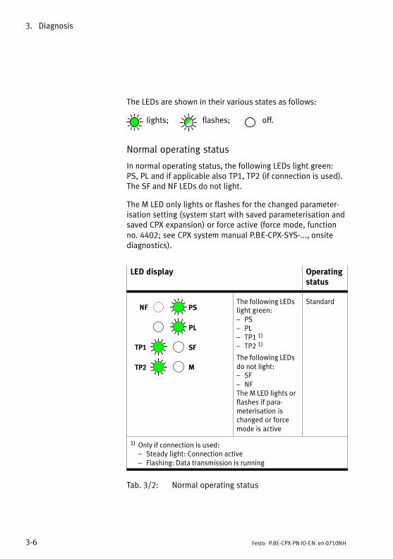
3. Diagnosis
3−6 Festo P.BE−CPX−PN IO−EN en 0710NH
The LEDs are shown in their various states as follows:
� lights; flashes; off.
Normal operating status
In normal operating status, the following LEDs light green: PS, PL and if applicable also TP1, TP2 (if connection is used).The SF and NF LEDs do not light.
The M LED only lights or flashes for the changed parameter�isation setting (system start with saved parameterisation andsaved CPX expansion) or force active (force mode, functionno. 4402; see CPX system manual P.BE−CPX−SYS−..., onsitediagnostics).
LED display Operatingstatus
PS
PL
SF
NF
TP1
MTP2
The following LEDslight green:� PS� PL� TP1 1)
� TP2 1)
The following LEDsdo not light:� SF� NFThe M LED lights orflashes if para�meterisation ischanged or forcemode is active
Standard
1) Only if connection is used: � Steady light: Connection active� Flashing: Data transmission is running
Tab.�3/2: Normal operating status

3. Diagnosis
3−7Festo P.BE−CPX−PN IO−EN en 0710NH
3.2.1 Network error display LED NF / Connection status LED TP1, TP2
NF (Network Failure)
LED (red) Sequence Status Error handling
LED is off
ON
OFF
No fault (if the green PS LED lights)
�
LED flashes
ON
OFF
Network connection not OK �possible causes:� Only before initial commis�
sioning has been done: Configuration defective, e.g. MAC−ID not configured
� Device name or devicenumber not correct
� defective IO Controller� Interrupted, short−circuited
or faulty network connection
Check ...
· the configuration
· the device names andthe device numbers
· the IO Controller· the network connection
TP1, TP2 (Link/Traffic 1, 2)
LED (green) Sequence Status Error handling
LED is off
ON
OFF
No physical network connection Check network connection/network cable
LED lights
ON
OFF
Network connection OK �
LED flickers orflashes 1)
ON
OFF
ON
OFF
� Flickering: Data transmissionis running
� Flashing, both LEDs at thesame rate: Module location
�
Module location: e.g. for faultdiagnostics or during configur�ation (section 2.1.4)
1) Appears as lit in the case of fast flickering. The light intensity depends on data traffic.
Tab.�3/3: Fault diagnostics using the LEDs NF and TP1/TP2
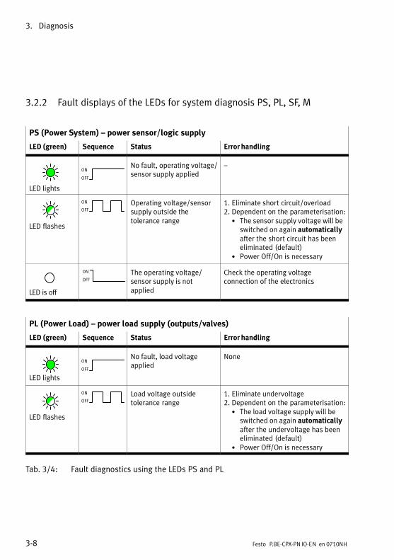
3. Diagnosis
3−8 Festo P.BE−CPX−PN IO−EN en 0710NH
3.2.2 Fault displays of the LEDs for system diagnosis PS, PL, SF, M
PS (Power System) � power sensor/logic supply
LED (green) Sequence Status Error handling
LED lights
ON
OFF
No fault, operating voltage/sensor supply applied
�
LED flashes
ON
OFF
Operating voltage/sensorsupply outside thetolerance range
1. Eliminate short circuit/overload2. Dependent on the parameterisation:
· The sensor supply voltage will beswitched on again automaticallyafter the short circuit has beeneliminated (default)
· Power Off/On is necessary
LED is off
ON
OFF
The operating voltage/sensor supply is notapplied
Check the operating voltageconnection of the electronics
PL (Power Load) � power load supply (outputs/valves)
LED (green) Sequence Status Error handling
LED lights
ON
OFF
No fault, load voltageapplied
None
LED flashes
ON
OFF
Load voltage outsidetolerance range
1. Eliminate undervoltage2. Dependent on the parameterisation:
· The load voltage supply will beswitched on again automaticallyafter the undervoltage has beeneliminated (default)
· Power Off/On is necessary
Tab.�3/4: Fault diagnostics using the LEDs PS and PL
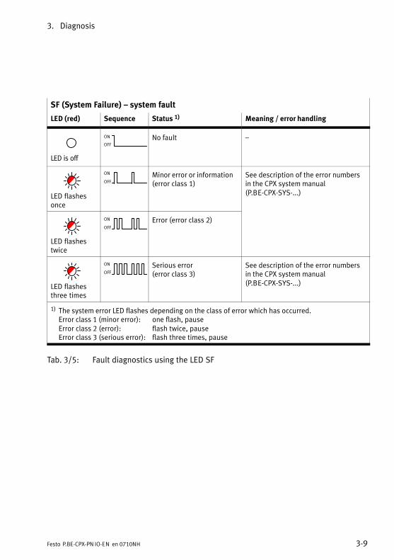
3. Diagnosis
3−9Festo P.BE−CPX−PN IO−EN en 0710NH
SF (System Failure) � system fault
LED (red) Sequence Status 1) Meaning / error handling
LED is off
ON
OFF
No fault �
LED flashesonce
ON
OFF
Minor error or information(error class 1)
See description of the error numbersin the CPX system manual(P.BE−CPX−SYS−...)
LED flashestwice
ON
OFF
Error (error class 2)
LED flashesthree times
ON
OFF
Serious error(error class 3)
See description of the error numbersin the CPX system manual(P.BE−CPX−SYS−...)
1) The system error LED flashes depending on the class of error which has occurred.Error class 1 (minor error): one flash, pauseError class 2 (error): flash twice, pauseError class 3 (serious error): flash three times, pause
Tab.�3/5: Fault diagnostics using the LED SF
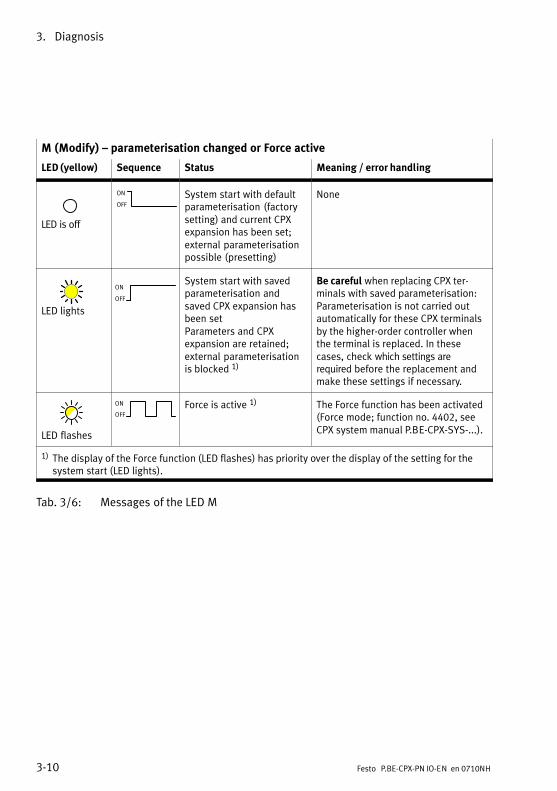
3. Diagnosis
3−10 Festo P.BE−CPX−PN IO−EN en 0710NH
M (Modify) � parameterisation changed or Force active
LED (yellow) Sequence Status Meaning / error handling
LED is off
ON
OFF
System start with defaultparameterisation (factorysetting) and current CPXexpansion has been set;external parameterisationpossible (presetting)
None
LED lights
ON
OFF
System start with savedparameterisation andsaved CPX expansion hasbeen setParameters and CPXexpansion are retained;external parameterisationis blocked 1)
Be careful when replacing CPX ter�minals with saved parameterisation:Parameterisation is not carried outautomatically for these CPX terminalsby the higher−order controller whenthe terminal is replaced. In thesecases, check which settings are required before the replacement andmake these settings if necessary.
LED flashes
ON
OFF
Force is active 1) The Force function has been activated(Force mode; function no. 4402, seeCPX system manual P.BE−CPX−SYS−...).
1) The display of the Force function (LED flashes) has priority over the display of the setting for thesystem start (LED lights).
Tab.�3/6: Messages of the LED M
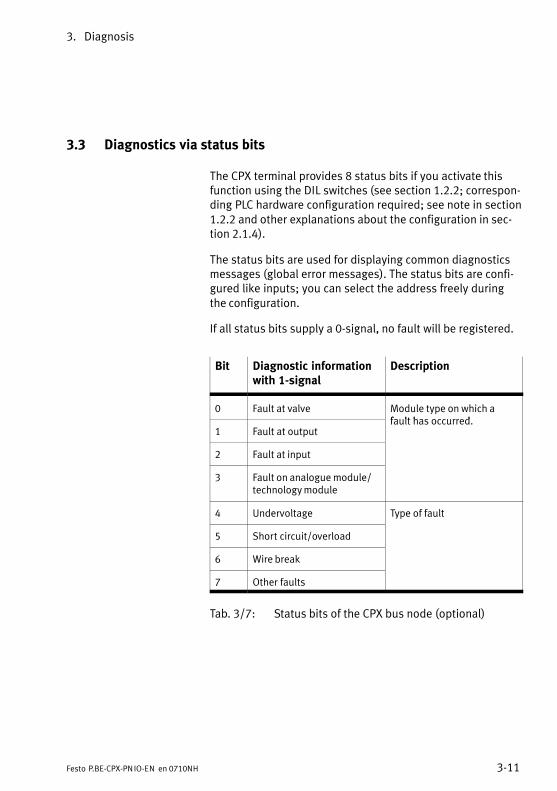
3. Diagnosis
3−11Festo P.BE−CPX−PNIO−EN en 0710NH
3.3 Diagnostics via status bits
The CPX terminal provides 8 status bits if you activate thisfunction using the DIL switches (see section 1.2.2; correspon�ding PLC hardware configuration required; see note in section1.2.2 and other explanations about the configuration in sec�tion 2.1.4).
The status bits are used for displaying common diagnosticsmessages (global error messages). The status bits are confi�gured like inputs; you can select the address freely duringthe configuration.
If all status bits supply a 0−signal, no fault will be registered.
Bit Diagnostic informationwith 1−signal
Description
0 Fault at valve Module type on which afault has occurred
1 Fault at outputfault has occurred.
2 Fault at input
3 Fault on analogue module/technology module
4 Undervoltage Type of fault
5 Short circuit/overload
6 Wire break
7 Other faults
Tab.�3/7: Status bits of the CPX bus node (optional)

3. Diagnosis
3−12 Festo P.BE−CPX−PNIO−EN en 0710NH
3.4 Diagnostics via the I/O diagnostic interface (STI)
The CPX terminal provides a 16−bit IO Diagnostics Interface(System Table Interface, STI) if you activate this functionusing the DIL switches (see section 1.2.2; corresponding PLChardware configuration required; see note in section 1.2.2and other explanations about the configuration in section2.1.4).
Further information can be found in the CPX system manualP.BE−CPX−SYS−... in the section Diagnostics and errorhandling.

3. Diagnosis
3−13Festo P.BE−CPX−PNIO−EN en 0710NH
3.5 Diagnostics via PROFINET
3.5.1 Basic information
PROFINET forms the basis for comprehensive diagnosticsfunctions and information over your automation network,e.�g. detailed module−related and channel−related statusinformation and error recognition in the online mode of theconfiguration software and in the PLC user program.
The following sections provide an initial view of the use of theonline diagnostics using the configuration and programmingsoftware (see section 3.5.2) and the user−specific diagnosticsusing function modules (see section 3.5.3).
Error reaction
The reaction of the CPX terminal for the following errors isdependent on the configured reaction of the controller (of theMaster), i.e. of the PLC, the SPS or the IPC and the parameter�ised Fail Safe setting:
� telegram failure
� stop of the controller (of the master)
� network interruption.
Depending on the parameterisation, the outputs (valves andelectric outputs) will be switched off (factory setting),switched on or retain their status.
Further information about the Fail Safe setting can be foundin the CPX system manual P.BE−CPX−SYS−...
3. Diagnosis
3−14 Festo P.BE−CPX−PNIO−EN en 0710NH
You can set two types of fault reactions of the controller:
� Hard fault reaction: the controller switches to the operating mode �STOP"when a fault occurs.
� Soft fault reaction: the controller remains in the operating mode �RUN"when�a fault occurs.
Warning· Ensure that valves and outputs are put into a safe stateif the faults named occur.
An incorrect status of the valves and outputs can lead todangerous situations.
NotePlease note the following if the outputs are reset afterPLC�stop, network interruption or fault:
� Single−solenoid valves move to the basic position.
� Double−solenoid valves remain in the current position.
� Mid−position valves move to the mid−position (depend�ing on valve type: pressurised, exhausted or blocked).

3. Diagnosis
3−15Festo P.BE−CPX−PNIO−EN en 0710NH
Fault types
The following table shows a list of all error types whichprovided further diagnostics information. The sections 3.5.2and 3.5.3 describe the access to these error types (based onSiemens STEP�7).
Value Fault type (standard) Value Error type (CPX−specific)
0 reserved 1016 Incorrect valve setting
1 Short circuit 1017 Valve: Switching counter, limit value exceeded
2 Undervoltage 1018 reserved
3 Overvoltage 1019 reserved
4 overload 1020 Parameterisation errors (configurable)
5 Overheating 1021 Parameterisation errors (data format)
6 Cable break 1022 Parameterisation errors (linear scaling)
7 Upper limit value exceeded 1023 Parameterisation error (digital filter)
8 Lower limit value exceeded 1024 Parameterisation error (lower limit value)
9 reserved 1025 Parameterisation error (upper limit value)
10 reserved 1026 Defective actuator supply
11 reserved 1027 CP module failure
12 reserved 1028 Defective CP configuration
13 reserved 1029 Short circuit in the CP string (CP line)
14 reserved 1030 Slave has no bus connection
15 reserved 1031 Channel failed
bold = relevant for CPX−FB33/FB34
Tab.�3/8: Error types for the diagnostics via PROFINET

3. Diagnosis
3−16 Festo P.BE−CPX−PNIO−EN en 0710NH
3.5.2 Online diagnostics with Siemens STEP 7
1. Start the PROFINET hardware configuration in yourconfiguration and programming software (e.�g. HW Configin Siemens STEP�7).
1 2
3 4 5 6
Fig.�3/2: Online diagnostics with Siemens STEP 7

3. Diagnosis
3−17Festo P.BE−CPX−PNIO−EN en 0710NH
2. Switch from offline to online (see Fig.�3/2 1�).
3. Click with the right−hand mouse button on the CPU inrack�2.
4. Click on �Module Information ..." in the displayed contextmenu (Module Information).The window �Module Information" will be displayed 3.
5. Click on the �IO Device Diagnostics" tab 4.
6. Click on the event and then on �Display" (show) 5.Diagnostics details are displayed in a new window 6.These provide more precise information for furtherprocessing. The information is independent of thecontroller used.
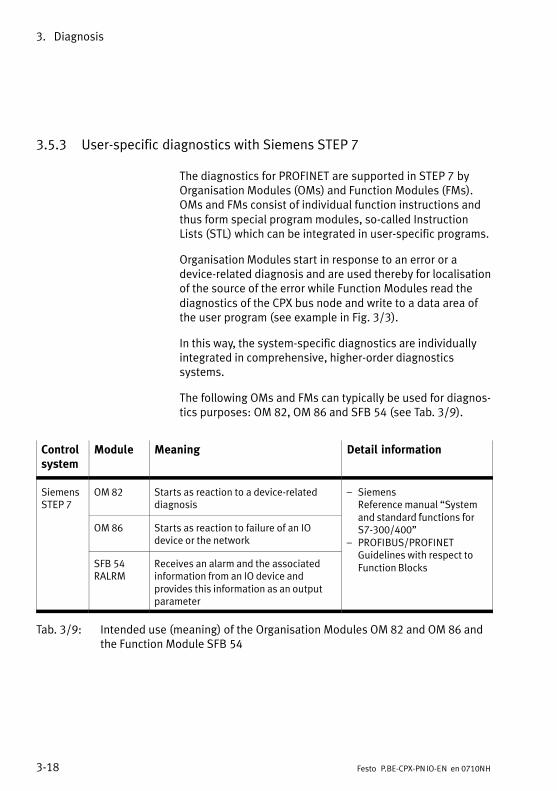
3. Diagnosis
3−18 Festo P.BE−CPX−PNIO−EN en 0710NH
3.5.3 User−specific diagnostics with Siemens STEP 7
The diagnostics for PROFINET are supported in STEP�7 byOrganisation Modules (OMs) and Function Modules (FMs).OMs and FMs consist of individual function instructions andthus form special program modules, so−called InstructionLists (STL) which can be integrated in user−specific programs.
Organisation Modules start in response to an error or adevice−related diagnosis and are used thereby for localisationof the source of the error while Function Modules read thediagnostics of the CPX bus node and write to a data area ofthe user program (see example in Fig.�3/3).
In this way, the system−specific diagnostics are individuallyintegrated in comprehensive, higher−order diagnosticssystems.
The following OMs and FMs can typically be used for diagnos�tics purposes: OM 82, OM 86 and SFB 54 (see�Tab.�3/9).
Controlsystem
Module Meaning Detail information
SiemensSTEP�7
OM 82 Starts as reaction to a device−relateddiagnosis
� SiemensReference manual �Systemand standard functions for
OM 86 Starts as reaction to failure of an IOdevice or the network
and standard functions forS7−300/400"
� PROFIBUS/PROFINETG id li i h
SFB 54RALRM
Receives an alarm and the associatedinformation from an IO device andprovides this information as an outputparameter
/Guidelines with respect toFunction Blocks
Tab.�3/9: Intended use (meaning) of the Organisation Modules OM 82 and OM 86 andthe Function Module SFB 54

3. Diagnosis
3−19Festo P.BE−CPX−PNIO−EN en 0710NH
Procedure for diagnostics with user programs
Always call the Function Module SFB�54 RALRM from theError Organisation Module which has been started by thecontroller, e.g. OM 82 or OM 86. A program example can befound in Fig.�3/3.
1. Call SFB�54 initially with the operating mode MODE = 0 inorder to determine the address of the IO device triggeringthe diagnostics.
2. For determining the diagnostics details:
� Call SFB�54 with the operating mode MODE = 2.
� Enter the diagnostics address of the CPX bus node inthe parameter F_ID (apply diagnostics address fromstep�1).
3. SFB 54 writes the diagnostics information to the AINFOoutput parameter.
STL ExplanationCALL ”RALRM” , DB54 Call SFB 54 MODE :=2 Operating mode Check the IO device with address in F_ID F_ID :=DW#16#7F3 Logical address of the CPX−FB33 MLEN :=255 Max. length in bytes NEW :=M54.0 New alarm received STATUS:=”DB_ALARM”.STATUS Error code of the SFB ID :=”DB_ALARM”.ID Starting address of the module with alarm LEN :=”DB_ALARM”.LEN Length of alarm information TINFO:=”DB_ALARM”.TINFO Target range OM start information (Task information) AINFO:=”DB_ALARM”.AINFO Target range Header / Additional information
(Alarm information)
Fig.�3/3: Program example in STL for reading diagnostics information

3. Diagnosis
3−20 Festo P.BE−CPX−PNIO−EN en 0710NH

Technical appendix
A−1Festo P.BE−CPX−PN IO−EN en 0710NH
Appendix A
A. Technical appendix
A−2 Festo P.BE−CPX−PNIO−EN en 0710NH
Contents
A. Technical appendix A−1 . . . . . . . . . . . . . . . . . . . . . . . . . . . . . . . . . . . . . . . . . . . . .
A.1 Technical specifications of bus node CPX−FB33 A−3 . . . . . . . . . . . . . . . . . . . . . . .
A.2 Technical specifications of bus node CPX−FB34 A−4 . . . . . . . . . . . . . . . . . . . . . . .

A. Technical appendix
A−3Festo P.BE−CPX−PNIO−EN en 0710NH
A.1 Technical specifications of bus node CPX−FB33
General CPX−FB33
General technical data see CPX system manual P.BE−CPX−SYS−...
Protection class according to EN 60529,completely installed, plug connector inserted orprovided with protective cap
IP65 / IP67
Protection against electric shock(protection against direct and indirect contactaccording to IEC/DIN EN 60204−1)
by means of a PELV circuit(Protected Extra−Low Voltage)
Module code (CPX−specific)� Remote I/O� Remote Controller
164215
Module identifier (in the Handheld)� Remote I/O� Remote Controller
FB33−RIO ProfiNet Remote I/OFB33−RC ProfiNet I/O Bus Node
Power supply CPX−FB33
Operating voltage�/�load voltage see CPX system manual P.BE−CPX−SYS−...
Own current consumption of bus node CPX−FB33� from operating voltage supply for electronics/
sensors (VEL/SEN)max. 120 mA(internal electronics)
Electrical isolation� PROFINET interfaces for VEL/SEN electrically isolated (transformer, 1500 V)
Power failure bridging time 10 ms
PROFINET CPX−FB33
Protocol PROFINET RT
Specification Network: Industrial Ethernet, based on IEEE 802.3; see also PROFINET Installation Guide
PNIO RT: IEC 61158, IEC 61784
Transmission speed 100 Mbit/s, Switched Fast Ethernet

A. Technical appendix
A−4 Festo P.BE−CPX−PNIO−EN en 0710NH
A.2 Technical specifications of bus node CPX−FB34
General CPX−FB34
General technical data see CPX system manual P.BE−CPX−SYS−...
Protection class according to EN 60529,completely installed, plug connector inserted orprovided with protective cap
IP65 / IP67
Protection against electric shock(protection against direct and indirect contactaccording to IEC/DIN EN 60204−1)
by means of a PELV circuit(Protected Extra−Low Voltage)
Module code (CPX−specific)� Remote I/O� Remote Controller
165216
Module identifier (in the Handheld)� Remote I/O� Remote Controller
FB34−RIO ProfiNet RJ45 Remote I/OFB34−RC ProfiNet RJ45 Bus Node
Power supply CPX−FB34
Operating voltage�/�load voltage see CPX system manual P.BE−CPX−SYS−...
Own current consumption of bus node CPX−FB34� from operating voltage supply for electronics/
sensors (VEL/SEN)max. 120 mA (internal electronics)
Electrical isolation� PROFINET interfaces for VEL/SEN electrically isolated (transformer, 1500 V)
Power failure bridging time 10 ms
PROFINET CPX−FB34
Protocol PROFINET RT
Specification Network: Industrial Ethernet, based on IEEE 802.3; see also PROFINET Installation Guide
PNIO RT: IEC 61158, IEC 61784
Transmission speed 100 Mbit/s, Switched Fast Ethernet

Index
B−1Festo P.BE−CPX−PN IO−EN en 0710NH
Appendix B

B. Index
B−2 Festo P.BE−CPX−PNIO−EN en 0710NH
Contents
B. Index B−1 . . . . . . . . . . . . . . . . . . . . . . . . . . . . . . . . . . . . . . . . . . . . . . . . . . . . . . . . .

B. Index
C−3Festo P.BE−CPX−PNIO−EN en 0710NH
A
Abbreviations, product−specific XII . . . . . . . . . . . . . . . . . . . .
Additional power supply 1−24 . . . . . . . . . . . . . . . . . . . . . . . . .
C
Configuration 2−3 . . . . . . . . . . . . . . . . . . . . . . . . . . . . . . . . . . . With Siemens Master 2−10 . . . . . . . . . . . . . . . . . . . . . . . . . .
Configuration examples 2−26 . . . . . . . . . . . . . . . . . . . . . . . . . .
ConnectingNetwork for the CPX−FB33 1−20 . . . . . . . . . . . . . . . . . . . . . . Network for the CPX−FB34 1−21 . . . . . . . . . . . . . . . . . . . . . . Power supply 1−23 . . . . . . . . . . . . . . . . . . . . . . . . . . . . . . . .
CP interface 2−5 , 2−26 . . . . . . . . . . . . . . . . . . . . . . . . . . . . . . .
CPA pneumatics 2−7 . . . . . . . . . . . . . . . . . . . . . . . . . . . . . . . . .
CPX−FEC 1−9 , 1−10 , 2−5 , 2−30 . . . . . . . . . . . . . . . . . . . . . . . .
D
Device master file (GSD) 2−9 . . . . . . . . . . . . . . . . . . . . . . . . . .
DIL switches 1−8 . . . . . . . . . . . . . . . . . . . . . . . . . . . . . . . . . . . .
Dismantling 1−5 . . . . . . . . . . . . . . . . . . . . . . . . . . . . . . . . . . . .
E
Electrical connection and display elements 1−4 . . . . . . . . . . .
F
FEC 1−9 , 1−10 , 2−5 , 2−30 . . . . . . . . . . . . . . . . . . . . . . . . . . . .
I
I/O diagnostic interface 3−12 . . . . . . . . . . . . . . . . . . . . . . . . . .

B. Index
C−4 Festo P.BE−CPX−PNIO−EN en 0710NH
Important user instructions VIII . . . . . . . . . . . . . . . . . . . . . . . .
Installation 1−5 . . . . . . . . . . . . . . . . . . . . . . . . . . . . . . . . . . . . .
Intended use V . . . . . . . . . . . . . . . . . . . . . . . . . . . . . . . . . . . . .
IP65/IP67 1−22 . . . . . . . . . . . . . . . . . . . . . . . . . . . . . . . . . . . . .
ISO pneumatics (VTSA) 2−7 . . . . . . . . . . . . . . . . . . . . . . . . . . .
L
LEDs 3−5 . . . . . . . . . . . . . . . . . . . . . . . . . . . . . . . . . . . . . . . . . .
M
Memory card 1−14 , 2−28 . . . . . . . . . . . . . . . . . . . . . . . . . . . . .
Midi/Maxi pneumatics 2−7 . . . . . . . . . . . . . . . . . . . . . . . . . . . .
Module parameters 2−37 . . . . . . . . . . . . . . . . . . . . . . . . . . . . .
N
NetworkCables 1−18 . . . . . . . . . . . . . . . . . . . . . . . . . . . . . . . . . . . . . . Connection 1−16 . . . . . . . . . . . . . . . . . . . . . . . . . . . . . . . . . .
Network cables 1−18 . . . . . . . . . . . . . . . . . . . . . . . . . . . . . . . . .
NF−LED 3−7 . . . . . . . . . . . . . . . . . . . . . . . . . . . . . . . . . . . . . . . .
Notes about the use of this manual VI . . . . . . . . . . . . . . . . . .
O
Operating mode 1−9 , 2−30 . . . . . . . . . . . . . . . . . . . . . . . . . . . .
P
ParameterisationApplication example 2−39 . . . . . . . . . . . . . . . . . . . . . . . . . . . Module parameters 2−37 . . . . . . . . . . . . . . . . . . . . . . . . . . .

B. Index
C−5Festo P.BE−CPX−PNIO−EN en 0710NH
Start parameterisation 2−32 . . . . . . . . . . . . . . . . . . . . . . . . . System parameters 2−34 . . . . . . . . . . . . . . . . . . . . . . . . . . .
PELV (Protected Extra−Low Voltage) 1−23 . . . . . . . . . . . . . . . .
Pictograms IX . . . . . . . . . . . . . . . . . . . . . . . . . . . . . . . . . . . . . .
Pin assignmentField bus interface of the CPX−FB33 1−20 . . . . . . . . . . . . . . Field bus interface of the CPX−FB34 1−21 . . . . . . . . . . . . . .
Plugs 1−20 , 1−21 . . . . . . . . . . . . . . . . . . . . . . . . . . . . . . . . . . . .
Power supply 1−23 . . . . . . . . . . . . . . . . . . . . . . . . . . . . . . . . . .
Protection class IP65/IP67 1−22 . . . . . . . . . . . . . . . . . . . . . . .
R
Remote controller 1−9 , 2−30 . . . . . . . . . . . . . . . . . . . . . . . . . .
S
Service V . . . . . . . . . . . . . . . . . . . . . . . . . . . . . . . . . . . . . . . . . .
SettingDiagnostic mode 1−12 . . . . . . . . . . . . . . . . . . . . . . . . . . . . . . DIL switches 1−8 . . . . . . . . . . . . . . . . . . . . . . . . . . . . . . . . . . Operating mode 1−9 . . . . . . . . . . . . . . . . . . . . . . . . . . . . . . .
Siemens Master 2−10 . . . . . . . . . . . . . . . . . . . . . . . . . . . . . . . .
Start parameterisation 2−32 , 2−33 . . . . . . . . . . . . . . . . . . . . . .
Status bits 2−4 , 3−11 . . . . . . . . . . . . . . . . . . . . . . . . . . . . . . . .
STEP 7HW Configurator 2−11 . . . . . . . . . . . . . . . . . . . . . . . . . . . . . . Online diagnostics 3−16 . . . . . . . . . . . . . . . . . . . . . . . . . . . .
Strain relief 1−18 . . . . . . . . . . . . . . . . . . . . . . . . . . . . . . . . . . . .
Switch cover, Removing and fitting 1−7 . . . . . . . . . . . . . . . . . .
Symbol files 2−9 . . . . . . . . . . . . . . . . . . . . . . . . . . . . . . . . . . . .
System supply 1−24 . . . . . . . . . . . . . . . . . . . . . . . . . . . . . . . . .
T
Target group V . . . . . . . . . . . . . . . . . . . . . . . . . . . . . . . . . . . . . .

B. Index
C−6 Festo P.BE−CPX−PNIO−EN en 0710NH
Technical specificationsCPX−FB33 A−3 . . . . . . . . . . . . . . . . . . . . . . . . . . . . . . . . . . . . CPX−FB34 A−4 . . . . . . . . . . . . . . . . . . . . . . . . . . . . . . . . . . . .
Text markings IX . . . . . . . . . . . . . . . . . . . . . . . . . . . . . . . . . . . .
TP−LED 3−7 . . . . . . . . . . . . . . . . . . . . . . . . . . . . . . . . . . . . . . . . .
V
Valve supply module 1−24 . . . . . . . . . . . . . . . . . . . . . . . . . . . .
VTSA pneumatics (ISO) 2−7 . . . . . . . . . . . . . . . . . . . . . . . . . . .


![CPX Terminal...Manual electronics CPX control block Type CPX−SF34 Type CPX−SF35 PCWORX integrated Network protocol PROFINET IO CPX Terminal Manual 570 541 en 1007NH [748 167] Contents](https://static.fdocuments.in/doc/165x107/5f0378aa7e708231d4094b43/cpx-terminal-manual-electronics-cpx-control-block-type-cpxasf34-type-cpxasf35.jpg)


![CPX terminal - Festo Electronics CPX field bus node Type CPX-FB32 Fieldbus protocol EtherNet/IP CPX terminal Manual 541 305 en 1111a [761 331] Contents and general instructions Festo](https://static.fdocuments.in/doc/165x107/5abd6a997f8b9aa15e8b8c21/cpx-terminal-festo-electronics-cpx-field-bus-node-type-cpx-fb32-fieldbus-protocol.jpg)

![Terminal CPX Busnode CPX-FB36 - FestoElectronics description Bus node Network protocol EtherNet/IP Modbus TCP Industrial Ethernet 2-Port 8024075 en 1309NH [8024081] Terminal CPX Busnode](https://static.fdocuments.in/doc/165x107/5e815d8a0a571a61d67077c3/terminal-cpx-busnode-cpx-fb36-festo-electronics-description-bus-node-network-protocol.jpg)