(Copyright 2011 FaceInMotion) · PDF fileabordagem permite ao utilizador, através de...
139
José Carlos Miranda I NTUITIVE R EAL T IME FACIAL I NTERACTION AND A NIMATION (Copyright 2011 FaceInMotion) A DISSERTATION in Computer Graphics Human Computer interaction Presented to the Faculty of Engineering of University of Porto in Partial Fulfillment of the Requirements for the Degree of Doctor of Philosophy Supervisor: Prof. Verónica Orvalho Co-Supervisor: Prof. Augusto de Sousa Porto, Janeiro 2013
-
Upload
vuongkhanh -
Category
Documents
-
view
214 -
download
2
Transcript of (Copyright 2011 FaceInMotion) · PDF fileabordagem permite ao utilizador, através de...

José Carlos Miranda
INTUITIVE REAL TIME
FACIAL INTERACTION AND ANIMATION
(Copyright 2011 FaceInMotion)
A DISSERTATION
in
Computer Graphics
Human Computer interaction
Presented to the Faculty of Engineering of University of Porto in Partial
Fulfillment of the Requirements for the Degree of Doctor of Philosophy
Supervisor: Prof. Verónica Orvalho
Co-Supervisor: Prof. Augusto de Sousa
Porto, Janeiro 2013

ii
This research is partially supported by:
Fundação para a Ciência e Tecnologia (SFRH/BD/46588/2008),
Instituto de Telecomunicações,
and the projects:
LIFEisGAME (ref: UTA-Est/MAI/0009/2009),
VERE (ref: 257695)
Golem (ref: 251415, FP7-PEOPLE-2009-IAPP).

Abstract
Facial Animation is the key element to express emotions in virtual characters.
One of the major challenges in the entertainment industry is to ensure that
the characters are highly expressive to reinforce the attention of the audience.
However, creating appealing and convincing facial expressions is a laborious
and time-consuming process since the representation of a 3D face is extremely
complex. Animators usually work with a control structure, named rig, in
order to simplify the manipulation of a 3D face. Nevertheless, this process
requires the full understanding of the rig’s structure and it also involves hard
and long manual work since the artist needs to manipulate each rig’s control
individually. This task can be tedious and demands a lot of time to create
believable results.
We propose a change of paradigm in the way a rig is controlled. The
method developed in this research allows to manipulate a rig structure through
free-hand drawing. It enables to handle a large number of rig’s controls at the
same time, through a single stroke drawn on the user interface. As several
rig controls are encapsulated in just one control curve, which is generated by
the drawn stroke, it is possible to create rapidly complex deformations with
just a single and continuous movement of the hand. This thesis presents a fa-
cial sketching control method, which is designed to reduce the time and effort
necessary to create facial expressions. Inspired in the way people draw, our
approach allows the user to sketch simple strokes which define the shape of
the deformation. These strokes can be drawn either directly on the 3D mesh
or on a virtual canvas, resulting in the deformation of the 3D face.
Our system was validated with a series of experiments. We highlight that
the sketching paradigm: (1) is simple and fast to create facial expressions (2-4
minutes), even without any previous training; (2) requires a shorter learning

iv
curve when compared to traditional rigging techniques. The results were su-
pervised by Technical and Art Directors, who approved the quality of the
created facial expressions. This is a crucial outcome for the system to be used
in CG productions. As a result, it significantly improves the production work-
flow, since it speeds up the creation of facial expressions through an intuitive
sketch-based interaction model.

Resumo
As indústrias do cinema e dos videojogos têm sofrido um forte crescimento
nos últimos anos. A necessidade de animar personagens virtuais que con-
sigam captar o interesse do espectador tornou-se um dos maiores desafios da
indústria do entretenimento. Um dos aspectos mais relevantes na animação
de personagens 3D é a manifestação de emoções através da expressão facial.
No entanto, criar expressões faciais convincentes e apelativas é um processo
moroso, uma vez que a face é composta por inúmeros detalhes que tornam a
sua manipulação extremamente complexa. De forma a simplificar a manipu-
lação de uma face, os artistas usam normalmente uma estrutura de controlo,
conhecida por rig. Mas, controlar um rig implica o total conhecimento da sua
estrutura interna e envolve um extenso trabalho manual, uma vez que o artista
necessita manipular os elementos do rig de forma individual. Este modo de-
scontínuo de controlar um elemento de cada vez requer muito tempo para
criar deformações faciais credíveis.
Nós propomos uma mudança de paradigma na forma de controlar o rig. O
método desenvolvido nesta investigação permite, sem qualquer necessidade
de conhecimento da estrutura interna do rig, a manipulação de um grande
número dos seus elementos em simultâneo. Através do desenho de uma sim-
ples curva, de um gesto contínuo, é agora possível criar deformações com-
plexas de uma forma célere. Esta tese apresenta um sistema intuitivo de con-
trolo facial, concebido para reduzir o tempo e esforço necessários à criação
de expressões faciais. Inspirada na forma como os artistas desenham, a nossa
abordagem permite ao utilizador, através de simples curvas, desenhar a forma
da deformação. Estas curvas podem ser desenhadas directamente sobre o
modelo 3D ou numa área de desenho bidimensional, denominada por canvas,
resultando na deformação da face 3D.

vi
O sistema desenvolvido foi validado com uma série de testes. Importa re-
alçar que : (1) o sistema é simples e rápido na criação de expressões faciais (2-
4 minutos), sem qualquer treino prévio; (2) o sistema apresenta uma curva de
aprendizagem mais rápida do que as técnicas tradicionais de rigging. Os re-
sultados foram supervisionados por profissionais da Indústria, que aprovaram
a qualidade das expressões faciais criadas através do método desenvolvido.
Este resultado é crucial para o sistema poder ser usado em produções profis-
sionais.

Acknowledgements
I would specially like to thank my professor Verónica Orvalho for her help
and dedication in this long journey. From the start, her extremely pleasant
attitude and knowledge in the area of facial animation were most encouraging
and motivating. It was great to work with a person like her. I would also like
to thank my professor Augusto de Sousa for his advices and friendly support.
I am specially grateful to Xenxo Alvarez, who dedicated many hours to
provide me with high quality test material. His constant feedback contributed
greatly to improve the system. I extend my thanks to Andrew Tucker for the
cartoon models.
Irina and José Soleno from Digital Animation School at University VER-
ITAS, Costa Rica, for the enthusiasm with which agreed to participate in
the validation process as well as the commitment and professionalism shown
when conducting the experiment.
My colleagues Miguel Salgado and Paulo Vieira for their unconditional
support in the statistical validation.
I specially thank Carla Martins and Jacqueline Fernandes for the text revi-
sion.
To all my lab colleagues who helped me with thoughts and comments dur-
ing the development of my research.
To all my professors of PRODEI (FEUP), for their teachings.
Finally, I want to thank my family and all my friends for their willingness
to listen to my formulations about my ongoing research, for their support and
their understanding. Special thanks should go to my parents, always avail-
able and happy for my arrival in Oporto and for their constant worry about

viii
my education. Most of all, I ultimately want to thank Anita and my hand-
some son Sebastião for their unconditional love, their numerous sacrifices,
understanding and their support over the last five years.
Now, I am back!

ix
To my son Sebasti

Contents
Abstract iii
Resumo v
Acknowledgements vii
List of Figures xiii
1 Introduction 1
1.1 Motivation . . . . . . . . . . . . . . . . . . . . . . . . . . . . 2
1.2 Method Overview . . . . . . . . . . . . . . . . . . . . . . . . 3
1.3 Main Contributions . . . . . . . . . . . . . . . . . . . . . . . 5
1.4 Outline . . . . . . . . . . . . . . . . . . . . . . . . . . . . . 6
2 Background and Related Work 7
2.1 Traditional Animation Pipeline . . . . . . . . . . . . . . . . . 7
2.1.1 Facial Rig . . . . . . . . . . . . . . . . . . . . . . . . 9
2.1.2 Rig Control Interface . . . . . . . . . . . . . . . . . . 12
2.2 Facial Animation . . . . . . . . . . . . . . . . . . . . . . . . 14
2.2.1 Shape Interpolation . . . . . . . . . . . . . . . . . . . 14
2.2.2 Geometric Deformation . . . . . . . . . . . . . . . . 16

CONTENTS xi
2.2.3 Physically-based . . . . . . . . . . . . . . . . . . . . 18
2.2.4 Motion Capture . . . . . . . . . . . . . . . . . . . . . 20
2.2.5 Retargeting . . . . . . . . . . . . . . . . . . . . . . . 22
2.3 Facial Parameterization . . . . . . . . . . . . . . . . . . . . . 24
2.3.1 FACS - Facial Action Coding System . . . . . . . . . 24
2.3.2 MPEG-4 Facial Animation . . . . . . . . . . . . . . . 26
2.4 Sketching Interaction . . . . . . . . . . . . . . . . . . . . . . 28
2.4.1 Sketch Acquisition . . . . . . . . . . . . . . . . . . . 29
2.4.2 Sketch Filtering . . . . . . . . . . . . . . . . . . . . . 31
2.4.3 Sketch Interpretation . . . . . . . . . . . . . . . . . . 32
2.5 Facial Sketching . . . . . . . . . . . . . . . . . . . . . . . . . 38
2.6 Discussion and Open Issues . . . . . . . . . . . . . . . . . . . 41
3 Sketch Express: A Control System for Facial Animation 43
3.1 Problem Statement . . . . . . . . . . . . . . . . . . . . . . . 43
3.2 Sketch Express Approach . . . . . . . . . . . . . . . . . . . . 44
3.3 Challenges . . . . . . . . . . . . . . . . . . . . . . . . . . . . 45
3.3.1 Facial Rig Control Problems . . . . . . . . . . . . . . 46
3.3.2 Sketching Problems . . . . . . . . . . . . . . . . . . 47
3.4 Sketch Express Overview . . . . . . . . . . . . . . . . . . . . 48
3.4.1 Innovation Issues . . . . . . . . . . . . . . . . . . . . 51
3.5 Sketching Control Method . . . . . . . . . . . . . . . . . . . 52
3.5.1 Sketching Representation . . . . . . . . . . . . . . . . 52
3.5.2 Sketching on the 3D Mesh . . . . . . . . . . . . . . . 55
3.5.3 Sketching on the Virtual Canvas . . . . . . . . . . . . 56
CONTENTS xii
3.6 Sketch Express Framework . . . . . . . . . . . . . . . . . . . 63
3.6.1 Setup . . . . . . . . . . . . . . . . . . . . . . . . . . 63
3.6.2 Facial Posing . . . . . . . . . . . . . . . . . . . . . . 64
3.6.3 Facial Animation . . . . . . . . . . . . . . . . . . . . 67
3.6.4 Facial Retargeting . . . . . . . . . . . . . . . . . . . 67
4 Results and Validation 70
4.1 Introduction . . . . . . . . . . . . . . . . . . . . . . . . . . . 70
4.2 Facial Posing Experiment . . . . . . . . . . . . . . . . . . . . 73
4.2.1 Experiment Design . . . . . . . . . . . . . . . . . . . 74
4.2.2 Experiment Results . . . . . . . . . . . . . . . . . . . 75
4.3 Facial Retargeting Experiment . . . . . . . . . . . . . . . . . 82
4.3.1 Experiment Design . . . . . . . . . . . . . . . . . . . 83
4.3.2 Experiment Results . . . . . . . . . . . . . . . . . . . 83
4.4 Performance Test . . . . . . . . . . . . . . . . . . . . . . . . 85
4.5 Case Study for Therapeutic Purposes: LIFEisGAME . . . . . 86
5 Conclusions and Future Work 88
5.1 Conclusion . . . . . . . . . . . . . . . . . . . . . . . . . . . 88
5.2 Future Work . . . . . . . . . . . . . . . . . . . . . . . . . . . 92
References 94
A Publications and Awards 112
A.1 Publications and Conferences . . . . . . . . . . . . . . . . . . 112
A.2 Invited Talks . . . . . . . . . . . . . . . . . . . . . . . . . . . 118
A.3 Honors and Awards . . . . . . . . . . . . . . . . . . . . . . . 119

List of Figures
1.1 Facial Sketching Control System Overview. left: the artist
can draw strokes directly on the 3D mesh or on a virtual can-
vas to create facial poses; right up: the created poses can be
used to generate facial animation; right down: one facial pose
transferred from the cat-woman character to different target
characters. . . . . . . . . . . . . . . . . . . . . . . . . . . . . 3
1.2 Two different implementations of the sketching control method;
left: Maya plugin for artistic purposes; right: LifeIsGame, a
learning system for therapeutic purposes. . . . . . . . . . . . 5
2.1 Different stages in a traditional animation pipeline. Notice
that the modeling, rigging and animation stages work in paral-
lel. The rigging stage produces a rig that will be manipulated
in order to animate the 3D model. Sometimes it is necessary
to readjust the rig after starting the animation stage, because
the rig does not perform the desired movements in the 3D model. 8
2.2 Blendshapes that represent the basic expressions: happy, sad,
surprise and angry (Copyright 2004 New Riders Publishing). . 9
2.3 A bone-driven rig based on a highly articulated facial skele-
ton structure. The skeleton is composed of around 34 bones.
(Copyright 2001-2007 Epic Games). . . . . . . . . . . . . . 10
2.4 Window-based UI; left: slider-based UI to control the activa-
tion of blendshapes for the stylized character’s eyebrows and
nostrils [Holly 2006]; right: slider-based UI based on FACS
for a realistic character’s face [Villagrasa and Susin 2009] . . . 12

LIST OF FIGURES xiv
2.5 UI in 3D space to control the character’s face; up: example of
2D controls by Alexander et al. [Alexander et al. 2009] and
Skonicky [Skonicky 2008]; down: example of 3D controls
by Komorowski et al. [Komorowski et al. 2010] and Grubb
[Grubb 2009]. . . . . . . . . . . . . . . . . . . . . . . . . . . 13
2.6 Linear Interpolation using blendshapes; left: Neutral pose;
right: "A" mouth shape; middle: Interpolated shape [Deng
and Noh 2007]. . . . . . . . . . . . . . . . . . . . . . . . . . 15
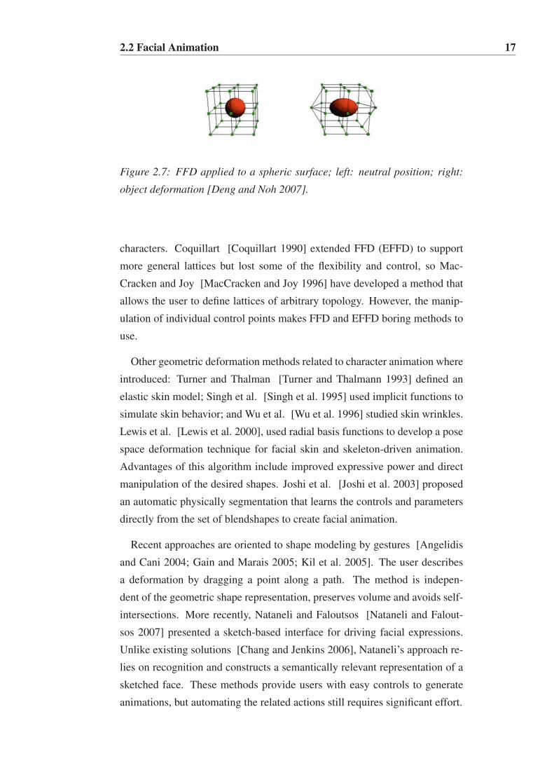
2.7 FFD applied to a spheric surface; left: neutral position; right:
object deformation [Deng and Noh 2007]. . . . . . . . . . . . 17
2.8 Impact of a colliding object on the face [Sifakis et al. 2005]. . 19
2.9 MoCap. Each sensor placed on the actor’s face represents a
marker on the 3D model (Copyright 2007 SoftImage). . . . . . 20
2.10 FACS; upper row: Sample single facial AUs; lower row: Sets
of AUs for basic expressions [Deng and Noh 2007]. . . . . . . 25
2.11 MPEG-4 Facial Animation; left: Facial Feature Points. The
specification defines 84 FPs for a face; right: Face Animation
Parameter Units (FAPU) [Balci 2004]. . . . . . . . . . . . . . 27
2.12 The sketching pipeline. . . . . . . . . . . . . . . . . . . . . . 29
2.13 The input sketch (left) is acquired as a sequence of point sam-
ples spaced irregularly (right). . . . . . . . . . . . . . . . . . 29
2.14 The Teddy sketch [Igarashi et al. 1999] is composed of sev-
eral strokes. The artist is creating the left arm with a new stroke. 30
2.15 The strokes are projected directly on the 3D model or on a 2D
virtual canvas by ray casting techniques [Olsen et al. 2009]. . . 30
2.16 Filtering Operations; left: smooth uniform resampling; right:
fit to a spline curve. . . . . . . . . . . . . . . . . . . . . . . . 31

LIST OF FIGURES xv
2.17 Evocative Systems; left: SKETCH is a classical example of
an Iconic System [Zelezenik et al. 1996]; right: Magic Can-
vas is an example of a Template Retrieval System [Shin and
Igarashi 2007]. . . . . . . . . . . . . . . . . . . . . . . . . . 33
2.18 An example of a 3D scene with objects retrieved from a database,
built in about two minutes [Eitz et al. 2012]. . . . . . . . . . . 34
2.19 left: The contour of an object transmit a lot of shape informa-
tion; right: the skeleton is used to create smooths 3D objects
[Olsen et al. 2009]. . . . . . . . . . . . . . . . . . . . . . . . 35
2.20 Construtive Systems; Free form models created from contour
sketches; left: example of rotational blending surfaces [Cher-
lin et al. 2005]; right: example of the inflation technique used
in Teddy [Igarashi et al. 1999]. . . . . . . . . . . . . . . . . . 35
2.21 "‘Augmenting"’ detail on object’s surface. left: An example
that allows to sketch extra features on the surface of the exist-
ing model [Olsen et al. 2005]; right: An example of additive
augmentation, which connects a new piece with an existing
model [Igarashi et al. 1999]. . . . . . . . . . . . . . . . . . . 37
2.22 Oversketching. left: bending a model so that a reference
stroke (red) is aligned with a target stroke (blue) [Igarashi
et al. 1999]; right: contour oversketching matches object’s
contour (yellow) to target strokes (green) [Nealen et al. 2005]. 37
2.23 Drawn keyframes are shown together with a representation of
the final 3D animation [Davis et al. 2003]. . . . . . . . . . . . 38
2.24 Motion Doodles. left: Gesture vocabulary; right: 2D motion
sketch and the resulting animation [Thorne et al. 2004]. . . . . 38
2.25 A reference curve (green) and target curve (blue) are drawn
on the face mesh to deform the lower lip [Chang and Jenkins
2006] . . . . . . . . . . . . . . . . . . . . . . . . . . . . . . 39

LIST OF FIGURES xvi
2.26 Face Poser System; left: an artist using the system; right: the
reference curve (blue) defines the moutht’s region that will
be deformed and the target curve (green) determines the new
shape of the mouth [Lau et al. 2009]. The top row shows the
inputs and the bottom row shows the results. . . . . . . . . . . 40
2.27 The 3D face (bottom row) is automatically deformed based
on the 2D portrait (top row) that is being interactively manip-
ulated by the user [Sucontphunt et al. 2008]. . . . . . . . . . . 40
2.28 Close-up of the mouth region; left: mouth deformation; mid-
dle: direct rig control; right: Osipa’s rig control; In traditional
techniques the user manipulates directly the individual con-
trols of the rig. Notice that it needs to manipulate 5 controls
individually to achieve the correspondent mouth deformation; 41
3.1 Facial Sketching Control System. left: the artist can draw
strokes directly on the 3D mesh or on a virtual canvas to create
facial poses; right up: the created poses can be used to gener-
ate facial animation; right down: one facial pose transferred
from the cat-woman character to different target characters. . . 45
3.2 User Interaction Model . . . . . . . . . . . . . . . . . . . . . 49
3.3 System Pipeline. Shows the main steps needed to create, an-
imate and retarget facial poses with our facial sketching con-
trol system. . . . . . . . . . . . . . . . . . . . . . . . . . . . 50
3.4 Sketching on the brow region on the 3D mesh. left: The stroke
is associated to a region with six joints located on the left
and on the right brow, the user deforms both brows with one
stroke; right: The stroke is associated to a region with three
joints located on the left brow, the user can only deform the
left brow with one stroke. . . . . . . . . . . . . . . . . . . . . 51

LIST OF FIGURES xvii
3.5 NURBS curve N generated by the input stroke S; left: input
stroke S; middle: sequence of point samples {s0, ..,sn−1} that
define S. Notice that the samples are spaced irregularly, de-
pending on the drawing speed; right: creation of the NURBS
curve with three edit points (ep0,ep1,ep2). This curve corre-
sponds to a region rigged with three joints. . . . . . . . . . . . 53
3.6 Curve fitting; the input stroke S (dashed line) and the curve N
generated with t = 3 edit points (full line) computed through
the Equation 3.1; left: without resampling; right: with resam-
pling; Notice that the fitting without resampling generated a
curve with the shape closer to the input stroke. . . . . . . . . . 54
3.7 Curve generated by the system from an erroneous stroke drawn
by the user; left: erroneous stroke S; middle: the curve N cor-
responds to a region rigged with three joints; right: the curve
N corresponds to a region rigged with five joints. . . . . . . . 54
3.8 Close-up of the mouth region. Notice how the mouth de-
formation are accordingly to the shape of strokes; left: two
strokes around the mouth; the NURBS of up stroke created
with 5 epi because the mouth up region has 5 joints; the
NURBS of down stroke has 3 epi because the mouth down
region was rigged with 3 joints; right: correspondent mouth
deformation. . . . . . . . . . . . . . . . . . . . . . . . . . . . 55
3.9 A stroke is drawn on the screen plane and projected onto the
mesh Rm by ray casting techniques. . . . . . . . . . . . . . . . 56
3.10 Deformation Space B; first row: deformation space B where
the joints movement take place, the initial position of the
joints are represented by highlighted circles; The value d rep-
resents the displacement to expand the deformation space;
second row: close-up of the mouth region with different d
values on the xy coordinate; Notice that the deformation space
increases from left to right. . . . . . . . . . . . . . . . . . . . 57
LIST OF FIGURES xviii
3.11 Sketching on predefined 2D canvas; up row: The method SKC
compute the mapping between the canvas C and the curve N
with the deformation space B and the region K; down row:
3D model deformation based on the strokes drawn on the 2D
canvas. . . . . . . . . . . . . . . . . . . . . . . . . . . . . . . 59
3.12 Tangent deformation over the surface; first row: close up of
the mouth region; second row: 2D representation of the defor-
mation steps; left: j0 is the initial position of the joint; middle:
j1 is the position after the mapping M, which is not tangent to
Rm; right: the final joint position j2 is calculated according to
j1, normal vector~n, point paux and the ray~r cast from it. . . . 60
3.13 Sketching on 2.5D canvas; upper row: the method SKC com-
pute the mapping between the bounding box C and the curve
N with the deformation space B and the region K; lower row:
deformation of the cheek and nose using a 2.5D canvas. . . . . 61
3.14 Displacement of the joints of the mouth region. left: joints
position defined by N j; right: joints position defined by N j+1
after a displacement was applied to each joint. Notice thal
all the joints of the mouth moved in the same direction of the
displacement vector ~d. . . . . . . . . . . . . . . . . . . . . . 62
3.15 Setup Module Overview. . . . . . . . . . . . . . . . . . . . . 63
3.16 2D Sketching Interface; left: 3D model deformation based on
the strokes drawn on the 2D canvas; right: two examples of
how the user can draw the strokes guided by the background
image. . . . . . . . . . . . . . . . . . . . . . . . . . . . . . 64
3.17 Facial poses created using the 2D canvas approach; top row:
3D models; down row: the strokes draw on the 2D canvas
generated the facial pose of the correspondent model. . . . . . 65

LIST OF FIGURES xix
3.18 3D Sketching Interface; left: sketching on both the 3D mesh
and the 2.5D canvas; right: multiples curves deforming the
same region; curve N1 drawn on the 3D mesh changes the
shape of the mouth; curve N2 drawn on the 2.5D canvas pulls
the mouth. Notice that two curves never overlap in the same
region. . . . . . . . . . . . . . . . . . . . . . . . . . . . . . . 65
3.19 Comparison of facial poses using the different UI configura-
tions of our sketching method. The box with an X means that
the expression is not possible to achieve with that UI config-
uration; right: two facial examples using the 2D canvas inter-
face and combining 2.5D canvas and direct sketching over the
3D mesh. . . . . . . . . . . . . . . . . . . . . . . . . . . . . 66
3.20 Keyframes extracted from a video sequence to show different
poses created using our method; final results generated with
an off-line render. . . . . . . . . . . . . . . . . . . . . . . . . 67
3.21 Retargeting from a source model to different target models.
Notice that the characters have different facial proportions
and styles. . . . . . . . . . . . . . . . . . . . . . . . . . . . . 68
3.22 Retargeting. Rows 1 to 4 show the retargeting of characters
with different facial proportions. Row 4 is the most extreme
case of retargeting as the source model proportions are very
different from the rest of the characters. Thus, the expression
on the target characters breaks the mesh (see mouth region).
Row 5 fixes the poses by adjusting the deformation window. . 69
4.1 We tested the system with six different characters: two real-
istic man, one asymmetric hybrid cat-woman, two child car-
toons and one alien-like fantastic creature. . . . . . . . . . . . 71
4.2 Rigs with different complexity; left: a simple rig based only
on a highly articulated facial skeleton, composed by 33 joints;
right: a complex rig based on joints, shapes and lattices to
provide additional deformation in the brows and mouth regions. 72

LIST OF FIGURES xx
4.3 The participants in the experiment were asked to recreate these
facial expressions using the respective interaction model: the
2D sketching interface, the 3D sketching interface and the tra-
ditional approach; left: Pose 1; middle: Pose 2; right: Pose 3. . 74
4.4 Only the expert participants found the sketching method eas-
ier and more intuitive to use. . . . . . . . . . . . . . . . . . . 76
4.5 User’s activities during the sketching tests for experts and
non-experts users. left: Number of clicks; right: Number of
curves created, modified and deleted. . . . . . . . . . . . . . . 77
4.6 All the participants, experts and non-experts, found sketching
on the canvas more intuitive than on the 3D mesh. . . . . . . . 78
4.7 We recorded the time it takes the participants to create each
expression with each interaction mode. This graph shows the
timing results for experts and non-experts users. . . . . . . . . 79
4.8 The time difference between experts and non-experts, to cre-
ate a pose, is less significant when they use the sketching ap-
proach. . . . . . . . . . . . . . . . . . . . . . . . . . . . . . 81
4.9 A participant realizing the retargeting experiment. . . . . . . . 83
4.10 The blue character was the one most difficult to perceive his
emotion during the Retargeting experiment. . . . . . . . . . . 84
4.11 Twenty six participants agree that the emotion of the blue
character is the most difficult to be perceived. . . . . . . . . . 85
4.12 LIFEisGAME, sketch-based interface of the game mode Build
a Face. right: the player can draw strokes on the 2D can-
vas and automatically deform the cartoon face model; bottom:
timeline to drag and drop the facial poses. . . . . . . . . . . . 87
5.1 Method generalization; left: The hand model has 19 joints,
which are controlled by five 2D fixed and predefined canvas,
one for each finger; right: The rope model has 9 joints, which
are controlled just by one 2.5D dynamic and billboard canvas. 92
Chapter 1
Introduction
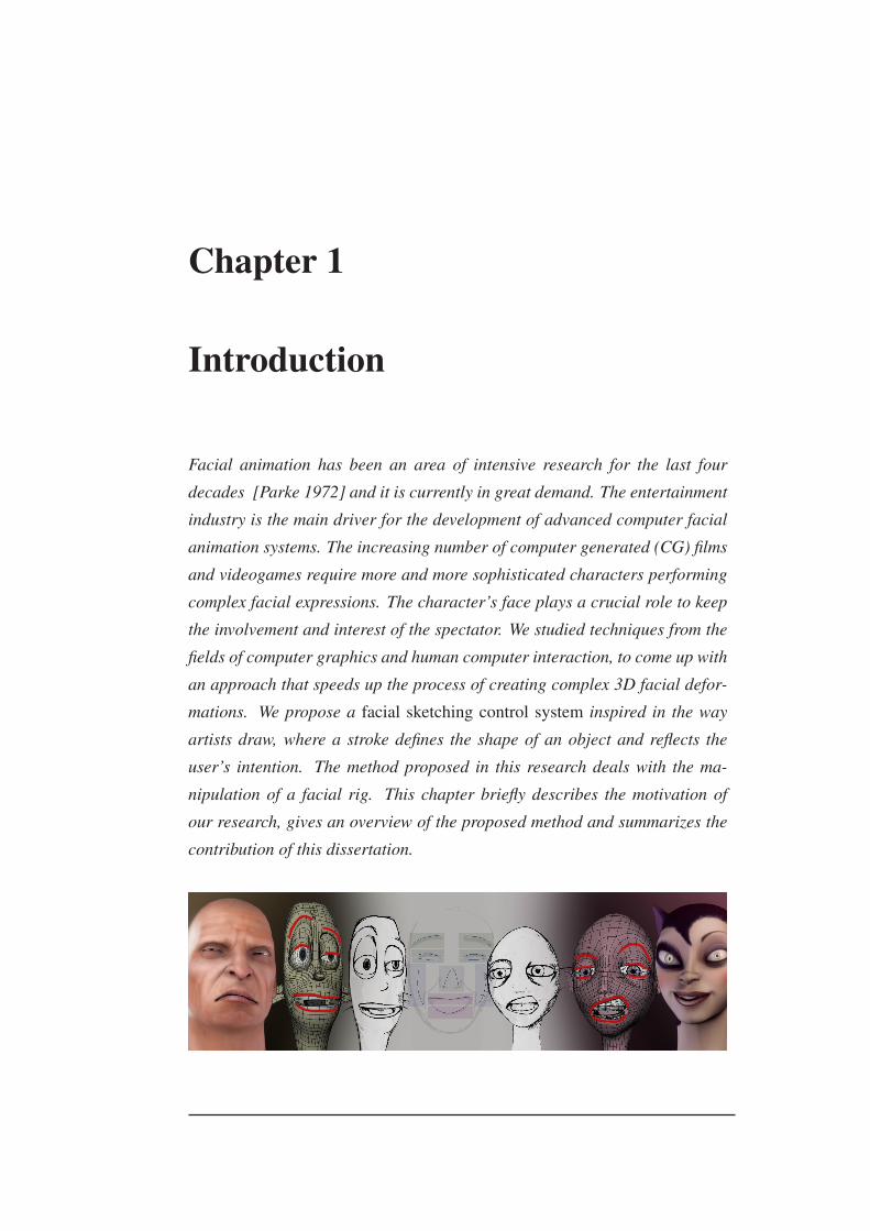
Facial animation has been an area of intensive research for the last four
decades [Parke 1972] and it is currently in great demand. The entertainment
industry is the main driver for the development of advanced computer facial
animation systems. The increasing number of computer generated (CG) films
and videogames require more and more sophisticated characters performing
complex facial expressions. The character’s face plays a crucial role to keep
the involvement and interest of the spectator. We studied techniques from the
fields of computer graphics and human computer interaction, to come up with
an approach that speeds up the process of creating complex 3D facial defor-
mations. We propose a facial sketching control system inspired in the way
artists draw, where a stroke defines the shape of an object and reflects the
user’s intention. The method proposed in this research deals with the ma-
nipulation of a facial rig. This chapter briefly describes the motivation of
our research, gives an overview of the proposed method and summarizes the
contribution of this dissertation.

1.1 Motivation 2
1.1 Motivation
The face performs an important role in verbal and non-verbal communication
for humans and 3D characters, but the representation of a face in 3D charac-
ters is complex. A face can express a variety of visual styles (from realistic
to cartoonish) and to produce a multitude of facial movements. As there is no
formal method for classifying character’s styles it is a challenge to represent
a 3D face [Orvalho et al. 2012]. The representation of a face becomes more
complex when working with 3D human faces since the simulation of all the
details like muscles, bones and wrinkles are necessary. These details’ simu-
lation must follow anatomic movements in order to show all the subtleties of
a facial expression. Moreover, it is not easy to achieve realistic results and
overcome the expectations of human observers, who are experts at watching
faces, because any inconsistency in a face detail is easily detected. Therefore,
generating an appealing facial animation is laborious and time-consuming.
The oldest method to animate 3D models is based on keyframe techniques.
These techniques interpolate all the vertex positions of a 3D model in a given
period of time. However, when the complexity of the model increases, editing
each vertex of the mesh quickly becomes impracticable. Thus, it is fundamen-
tal to create a simplified structure to control the 3D model. Luxo Jr. [Pixar
1986] was the first to introduce a control technique to manipulate a desk lamp
articulated structure, instead of editing each vertex of the model. Since then,
advances in animation control techniques gave origin to what we know today
as rig [Magnenat-Thalmann et al. 1988a]. However, it was only in the 90s
that the rigging concept emerged due to the increasing need to have charac-
ters performing complex actions. Toy Story [Porter 1997] is the first CG
film bringing the principles of classic animation [Lasseter 1987] and rig con-
cepts into a 3D production. Nowadays, rigged models are generally used by
animators.
We can loosely define a generalized rig as a structured set of elements that
can modify an associated geometry by manipulating a set of controls in a
User Interface (UI). The rig can range from a simple bone system to a more
sophisticated hierarchy of elements (blendshapes, wire, lattice, constraints).
As the complexity of the rig increases, creating the required different poses
of the model by hand quickly becomes impractical. Thus, mastering the ma-

1.2 Method Overview 3
nipulation of rigs in a short period of time is challenging for artists and al-
most impossible for non-experts. User interfaces associated to the rig provide
high-level controls, masking most of the technical difficulties of the anima-
tion process. It eases the rig manipulation, thus helping the artist to focus
on the creative issues. While high-level rigs can simplify the animation pro-
cess, encapsulating a set of rig elements on a single control object presents a
particularly challenging problem:
to design an interface that intuitively maps the manipulation of the control
object to the model deformation, while increases the rig usability.
1.2 Method Overview
We focus our research on the design and definition of a rigging control method
for the manipulation of 3D characters for films and videogames. The overall
goal of this thesis is to define complex 3D deformations with just a free-
hand drawing. We propose a facial sketching control system based on simple
strokes drawn on a 3D mesh or on a virtual canvas (see Figure 1.1).
Figure 1.1: Facial Sketching Control System Overview. left: the artist can
draw strokes directly on the 3D mesh or on a virtual canvas to create facial
poses; right up: the created poses can be used to generate facial animation;
right down: one facial pose transferred from the cat-woman character to dif-
ferent target characters.
Sketching is an increasingly popular way to create, deform or control 3D
models. However, while most of the sketching approaches act directly on
the 3D mesh of the model, the proposed method should act on the rig of the

1.2 Method Overview 4
model. The innovation of our work lies in the manipulation of the underlying
rig’s structure, instead in the manipulation of the mesh’s vertices.
We propose a change of paradigm in the way a rig is controlled. In most
of traditional approaches, the elements of the rig are controlled individually
(one by one), in a discontinuous way. In the proposed method it is permitted
to control a rig in a continuous way: a user can manipulate several elements
of the rig at the same time, using just one stroke. This enables the fast creation
of complex deformations by using just a single hand continuous movement.
Despite the loss of precision, which usually is associated to the sketch-based
interfaces, in the proposed approach the quality of the deformations will be
constrained by the rig.
Furthermore, it becomes possible for the user to control an object without
the understanding of rig’s structure of the correspondent 3D model, so it will
permit intuitively to create facial poses from scratch without manipulating
complex rigs. As a result, rapid animation in real time will be performed by
sketching strokes directly on the 3D mesh or on a virtual canvas. Addition-
ally, the created poses can be automatically transferred to different models by
storing the 2D strokes, so they can be reused in different models.
The hypothesis of this research intends to prove that:
using a continuous sketching interaction, it is possible to simplify the rig con-
trol process, in order to generate complex deformations on any 3D face, in
real time.
We illustrate the method proposed in this thesis with two implementations:
one for artistic purposes embedded in the software Maya 1 and the other for
learning in therapeutic purposes, developed as a stand-alone application (see
Figure 1.2). We used several facial models of distinct artistic styles, from
photorealistic to cartoon, and, additionally, we have carried out several exper-
iments with artists. The user study shows that users can create appealing 3D
facial expressions in just a few minutes, without previous training. The facial
poses were instantly transferred to other characters with 82% of accuracy due
to the new retargeting method developed.
1http://usa.autodesk.com/maya/

1.3 Main Contributions 5
Figure 1.2: Two different implementations of the sketching control method;
left: Maya plugin for artistic purposes; right: LifeIsGame, a learning system
for therapeutic purposes.
1.3 Main Contributions
The key contributions of this dissertation to the field of Computer Graphics
and Human Computer Interaction are:
• a facial sketching control method to manipulate a rig structure through
free-hand drawing; it allows to manipulate, in a continuous way, a large
number of rig elements and, as a consequence, to create complex 3D
deformations by a single control curve: the stroke;
• a depth constraint method to work on the top of the rig; it automates
the movement of the rig elements on the Z-axis, which automatically
maps the deformation from 2D to 3D;
• a retargeting method to transfer facial expressions between 3D char-
acters; it allows to reuse the same strokes in different models to generate
facial poses.
As a result, our facial sketching system can impact the film and videogame
industries. It can be integrated into existing animation production pipelines
and significantly improve the workflow, as it speeds up the creation of facial
poses through an intuitive and interactive sketching method. Furthermore,
the results from our project can benefit other areas where the face plays an
important role in visual communication, such as psychotherapy, broadcasting,
criminology, virtual worlds and others.
1.4 Outline 6
1.4 Outline
The remaining chapters of the dissertation are organized as it follows:
Chapter 2. Describes the complexity of the facial rigging process and dis-
cusses different methods related to facial synthesis: shape interpolation,
geometric deformation, physically-based, motion capture and retarget-
ing. It briefly describes facial parameterization, Facial Action Coding
System (FACS) and the MPEG-4 Facial Animation standard. After that,
it details the pipeline of a sketch-based system: sketch acquisition, fil-
tering and interpretation, and then it describes some systems that use
sketching to generate facial deformation. Lastly, it discusses several
open issues related to the fields of facial animation and sketching inter-
action.
Chapter 3. Describes Sketch Express, the proposed control system to cre-
ate facial expressions through free-hand sketching. The chapter begins
by defining the major problems found and presenting some main chal-
lenges to overcome at both levels, the rig control and the sketching in-
teraction model. After that, it gives an overview of the developed facial
control system and then it details the sketching control method devel-
oped in this research. Lastly, it presents the framework implemented
for prototyping purposes.
Chapter 4. Describes two experiments conducted with users: Facial Posing
Experiment and Facial Retargeting Experiment. The results obtained
from experiments were analyzed after statistical validation. It also sum-
marizes the results of a test to measure the system performance. Lastly,
it presents an application of the developed sketching method in the psy-
chotherapy field.
Chapter 5. Discusses the work developed in this research, its implications
and future trends.

Chapter 2
Background and Related Work
One of the most important aspects in virtual character animation is facial ex-
pression. The central research goal is to create real time facial synthesis with
high artistic quality. But, generating correct skin deformation raises several
challenges at the level of facial rig control. This chapter begins by defining
a facial rig as a structure that needs to be controlled by an user interface.
Then comes an extensive study of the published literature and previous work
in facial synthesis and parameterization. After that and motivated by the ease
of freehand drawing to simplify the user interaction model, we focus our re-
search on the study of the sketch-based interfaces. The chapter ends with a
discussion about several open issues related to the research fields of facial an-
imation and sketching interaction. After reading this chapter, you should have
an understanding of the underlying work that is related with this research.
2.1 Traditional Animation Pipeline
The film and videogame industries typically use a production environment,
which is divided into the following stages: concept design, modeling, rigging
and animation (see Figure 2.1). After the concept design of a character is
finished, 3D artists need to model, rig and animate the character [Schleifer
et al. 2002]. During the modeling stage the geometry of the model is created
based on the visual requirements defined during the concept design. After

2.1 Traditional Animation Pipeline 8
that, a control structure, usually named rig, is defined and the model is ready
to become animated. Rigging is then an intermediate process that links the
modeling and animation stages within a traditional animation pipeline.
Figure 2.1: Different stages in a traditional animation pipeline. Notice that
the modeling, rigging and animation stages work in parallel. The rigging
stage produces a rig that will be manipulated in order to animate the 3D
model. Sometimes it is necessary to readjust the rig after starting the anima-
tion stage, because the rig does not perform the desired movements in the 3D
model.
The person responsible for rigging a character, usually known by Rigger,
needs to interact with both, the modelers and the animators, in order to realize
how to create the rig to improve the model’s deformation. It is his responsi-
bility to provide an efficient and intuitive interface that allows the animator to
control the character’s face [Parke and Waters 2008].
In the case of complex facial models, it is challenging to setup a consistent
rig that can work well for every possible motion. It is usual that after the
rig is defined, the animator asks the rigger to generate new controls, because
the character needs to support new deformations or just needs to look bet-
ter. Thus, the overall process gets iterative and, therefore, becomes a serious
problem in a CG production pipeline [Orvalho et al. 2012].
The following sections define a facial rig as a structure that needs to be
controlled. It also describes the different approaches to manipulate a rig.
2.1 Traditional Animation Pipeline 9
2.1.1 Facial Rig
One of the most complex tasks in facial animation is the creation of a rig
that adapts the face model to the shape and visual style of each character
and produces convincing facial expressions. When creating a facial rig it is
important to consider the face’s morphology and behavior [Orvalho et al.
2012]. The morphology is related to the shape and visual appearance of the
3D face. The behavior corresponds to the facial movements the 3D model
will do. Given the fact that there is a lack of a formal rig definition, different
authors and riggers have adopted a variety of explanations. For example,
according to Falk et al. [Falk et al. 2004], "‘Rigging is the process of taking
a static, inanimate computer model and transforming it into a character that
an animator can edit frame-by-frame to create motion"’. McLaughlin and
Sumida [McLaughlin and Sumida 2007] state that "‘Rigging is the system
engineering process that allows surface deformation"’. Based on these two
definitions, we can define a rig as a set of controls that can be manipulated to
deform a 3D model, which is a process analogous to setting up the strings that
control a puppet.
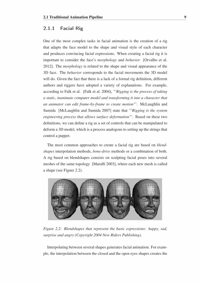
The most common approaches to create a facial rig are based on blend-
shapes interpolation methods, bone-drive methods or a combination of both.
A rig based on blendshapes consists on sculpting facial poses into several
meshes of the same topology [Maraffi 2003], where each new mesh is called
a shape (see Figure 2.2).
Figure 2.2: Blendshapes that represent the basic expressions: happy, sad,
surprise and angry (Copyright 2004 New Riders Publishing).
Interpolating between several shapes generates facial animation. For exam-
ple, the interpolation between the closed and the open eyes shapes creates the

2.1 Traditional Animation Pipeline 10
blinking eye animation of the character. So, creating a rig of a facial model
using only blendshapes, is a hard task, since the artist needs to sculpt a large
number of shapes 1 to provide deformation over every region of the face. The
artist controls the weight of the shapes and blend them to generate the ani-
mation. This process needs to be repeated for every character that is going
to be animated and consumes a long time for production. Several researchers
[Orvalho 2007; Dutreve et al. 2008; Dutreve et al. 2010] proposed a method
to automatically transfer shapes among different characters, considerably re-
ducing the time of production.
A bone-driven rig is based on a highly articulated facial skeleton structure
bind to the 3D surface. To create this binding between the skeleton and the
mesh it is necessary to define how the skeleton bones influence each vertex
surface. Normally, this is done through smooth skinning algorithms [Yang
and Zhang 2006]. As each vertex is only animated by the bones around it,
much more planning must go into rigging process of each model [Ward
2004]. Figure 2.3 shows an example prepared to be animated.
Figure 2.3: A bone-driven rig based on a highly articulated facial skeleton
structure. The skeleton is composed of around 34 bones. (Copyright 2001-
2007 Epic Games).
The skeletal approach allows the creation of softer movements than the
blendshapes method, although it requires a longer time of preparation to get
good results [Ward 2004]. In videogames production, bone-based rigs are
widely used together with Motion Capture techniques (see section 2.2.4),
which each bone of the rig can represent a motion sensor placed on the face.
Two main concerns in computer animation are, naturally, time and produc-
1In the film The Lord of the Rings: The Two Towers, the rig of the character Gollum
implied the creation of 675 shapes [Fordham 2003].
2.1 Traditional Animation Pipeline 11
tion costs. So, it is essential to guarantee that the rigging technique is the one
that best suits the project. Both methods based on blendshapes and "bones"
present advantages and disadvantages. A typical choice is to combine blend-
shapes with a skeletal approach, which provides a rig with the flexibility and
smoothness of a bone-driven system, as well as, the expressiveness of blend-
shapes [Lewis et al. 2000; Lewis and Anjyo 2010].
In face regions where neither shapes nor "bones" produce the desired re-
sults, it is possible to add new layers of deformation [Orvalho 2007]. These
new objects are commonly denominated as influence objects or deformable
objects; they add control and give additional realism to the animation. NURBS
curves or FFD grids (see section 2.2.2) are an example of this type of defor-
mation objects, which can be added in some regions of the face in order to
emphasize some characteristics, like muscles, wrinkles, etc.
As a summary, a typical rig includes the following elements:
1. Skeleton: hierarchical and articulated structure composed by bones and
joints. Each bone is connected by two joints. The deformation of the
mesh is influenced by the action of the skeleton’s joints.
2. Deformable objects: any object that can be deformed, like NURBS
curves or surfaces, polygonal meshes, lattice objects and others. These
objects, connected to the skeleton, add extra control and realism to the
animations and can represent the geometry of, for example, facial mus-
cles and simulate its behavior.
3. Skinning: the process of binding skeleton’s joints to the correspon-
dent vertex of the polygonal mesh and to the deformable objects. There
are different skinning techniques, like smooth or rigid skinning [Lar-
boulette et al. 2005; Yang and Zhang 2006], and the most important task
during this process is the weight definition [Wang and Phillips 2002].
The weight is the degree of influence of a joint over a vertex during
deformation. Each joint and deformable object has its own weight dis-
tribution map, which defines the amount of influence they will exert on
the model during animation [Mohr and Gleicher 2003].
4. Shapes: set of poses or facial expressions. The interpolation of the
different shapes results in the facial model animation.

2.1 Traditional Animation Pipeline 12
5. Constraints: restrictions of position, rotation and scale in order to
avoid impossible and unwanted movements.
The rig definition is an iterative process that requires great amount of pro-
duction time, experience and knowledge about the facial anatomy. An expe-
rienced artist can take from one to several weeks to rig a character, depending
on the complexity of the rig [Ritchie 2006].
2.1.2 Rig Control Interface
Usually, to deform a 3D face, the artist needs to understand the rig as a struc-
ture that has to be manipulated by an user interface (UI). The rig’s UI can be
defined as a set of controls that allows the user interaction in order to modify
the underlying geometry of the 3D model. There are a considerable amount
of different approaches to handle the controls of a rig. These approaches to
the UI for rigging can be compiled into two categories: window-based and
viewport-based, which can also be combined.
Window-based UI uses a traditional interface design to provide direct input
of values. The UI is built in a separate window, not in 3D space. Holly
[Holly 2006] has built a UI with sliders that ease the manipulation of controls
located in the facial skin surface of a stylized character (see Figure 2.4 left).
Villagrasa and Susin [Villagrasa and Susin 2009] have built an UI based on
FACS [Ekman and Friesen 1978]. By editing parameters, their system allows
to move the muscles of a realistic character to generate different expressions
of the face (see Figure 2.4 right).
Figure 2.4: Window-based UI; left: slider-based UI to control the activa-
tion of blendshapes for the stylized character’s eyebrows and nostrils [Holly
2006]; right: slider-based UI based on FACS for a realistic character’s face
[Villagrasa and Susin 2009]
2.1 Traditional Animation Pipeline 13
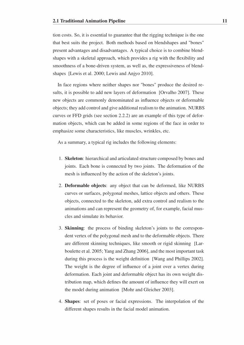
Viewport-based UI provides a set of controls (2D or 3D) that make part of
the 3D space where the model is located. Several authors [Osipa 2007; Neale
2008; Maguire 2008; Skonicki 2008; Alexander et al. 2009; Grubb 2009;
Komorowski et al. 2010] have created the UI in 3D space to control the char-
acters’ face. Osipa [Osipa 2007] proposed a set of 2D controls constrained
to a square to drive the activation of blendshapes. Alexander et al. [Alexan-
der et al. 2009] have used the same technique of a 2D constrained space, but
with an anthropomorphic shape control. The blendshapes are controlled by
a UI built with arrow-shaped control curves. Each arrow of the UI controls
the correspondent region of the 3D face (see Figure 2.5 up left). Skonicky
[Skonicki 2008] has changed the position of the facial bones through the 2D
controls located in the UI (see Figure 2.5 up right). Grubb [Grubb 2009] and
Komorowski et al. [Komorowski et al. 2010] have handle a set of 3D controls
to drive the facial deformation in the 3D space (see Figure 2.5 down).
Figure 2.5: UI in 3D space to control the character’s face; up: example of 2D
controls by Alexander et al. [Alexander et al. 2009] and Skonicky [Skonicky
2008]; down: example of 3D controls by Komorowski et al. [Komorowski et
al. 2010] and Grubb [Grubb 2009].
The following section discusses the most relevant methods related to facial
animation.

2.2 Facial Animation 14
2.2 Facial Animation
Human facial expression has been studied for more than one hundred years.
Computerized facial animation began in the 70’s. It is interesting to under-
stand that the techniques that are used nowadays come from the principles
developed more than forty years ago. The first 3D facial animation was cre-
ated by Frederic Parke [Parke 1972]. Since then, different approaches have
been developed and were classified into two major categories: 3D Geometric
manipulation and 2D image manipulation. It is not easy to fit a certain method
into one of these categories, since the boundaries between both are not clearly
defined. In 1998, Noh and Neumann [Noh and Neumann 1998] and more
recently Deng and Noh [Deng and Noh 2007] presented a survey that clas-
sifies different facial animation methods. Facial analysis and comprehension
is another area that influences recent facial synthesis tendencies. Zhao et al.
[Zhao et al. 2003] presented a detailed document about facial recognition that
gives a different perspective and complement this research field.
The following sections describe the most common approaches used for fa-
cial modeling and animation: Shape interpolation, Geometric deformation,
Physically-based, Motion Capture and Retargeting.
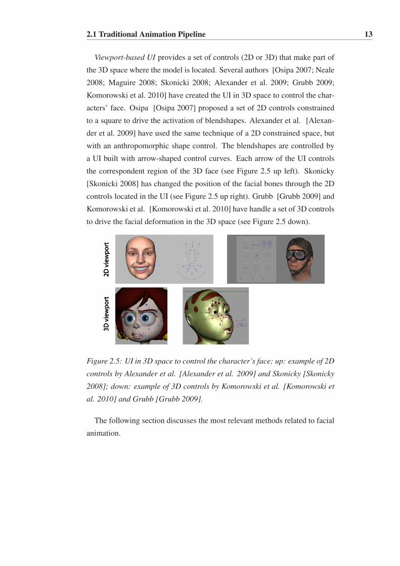
2.2.1 Shape Interpolation
Shape interpolation is the most commonly employed technique in facial ani-
mation. It consist on specifying complete face models for a given set of points
in time, called blendshapes, key poses or morph targets. Each blendshape
represents a specific face deformation and the models for the intermediate
frames are generated by interpolation. The simplest case to be mentioned
corresponds to an interpolation between two keyframes at different positions
in time (see Figure 2.6). For blendshape interpolation, all the shapes must
have the same structure. That is, they must have the same number of vertices
with the same connectivity and each vertex must have a matching vertex in
the other blendshapes. A face deformation then becomes a linear combination
of a number of blendshapes.
Linear interpolation is frequently used because of its simplicity [Bergeron
and Lachapelle 1985; Pighin et al. 1998], but a cosine interpolation function
2.2 Facial Animation 15
Figure 2.6: Linear Interpolation using blendshapes; left: Neutral pose; right:
"A" mouth shape; middle: Interpolated shape [Deng and Noh 2007].
[Waters and Levergood 1993] or other variations, such as spline, can offer ac-
celeration and deceleration effects at both limits extremities of an animation.
Bilinear interpolation creates a greater variety of facial expressions than lin-
ear interpolation, when, instead of two, four keyframes are involved [Parke
1974]. When combined with simultaneous image morphing, bilinear inter-
polation produces a broad range of different facial expressions [Arai et al.
1996].
There were recently some attempts to improve muscle actuation based on
blendshape animations [Choe and Ko 2001; Sifakis et al. 2005]. The Pose
Space Deformation technique introduced by Lewis et al. [Lewis et al. 2000]
offers a framework for example-based interpolation, which can be used in
blendshape facial animation. In their work, the deformation of a face is dealt
as a function of some set of abstract parameters (such as lip stretcher or nose
wrinkler) and scattered data interpolations creates a new facial pose.
Interpolations are quick and can easily create facial animations. Neverthe-
less, they show limitations when creating a broad variety of realistic facial
expressions. Combinations of independent facial poses, like eye closed while
smiling, are difficult to produce and blendshapes often interfere with each
others [Deng and Noh 2007], which forces animators to go backwards and
forwards to readjust the weights of blendshapes. So, further research is re-
quired to automate the blendshape approach, which currently requires a lot of
manual work to perform a successful animation. Lewis et al. [Lewis et al.
2005] introduced a method to automatically reduce blendshape interferences.
Recent advances show that blendshape interpolation is being used in com-
bination with other animation methods, like performance-driven techniques

2.2 Facial Animation 16
[Igarashi et al. 2005; Deng et al. 2006; Li and Deng 2008; Liu et al. 2011], to
significantly reduce the amount of manual work.
When the facial model complexity increases, the manipulation of a large
number of blendshapes becomes a problem. Lewis and Anjyo [Lewis and An-
jyo 2010] presented a method for direct manipulation of blendshapes. Their
method uses PCA to automatically create a space where each blendshape has a
correspondent position in the 3D space. They show that a single direct manip-
ulation in the 3D space is usually equivalent to a large number of edits using
the traditional sliders, resulting in a simple and efficient technique, compatible
with existing blendshapes approaches. Later, Seo et al. [Seo et al. 2011] ex-
tended the previous method to control efficiently and intuitively a large num-
ber of blendshapes with a hardware-accelerated optimization. Their approach
leads to a huge improvement in both storage and processing efficiency without
suffering any visual artifacts.
Recently, Liu et al. [Liu et al. 2011] proposed a method to automatically
explore the non-linear relationship of blendshape facial animation from cap-
tured facial expressions. The results of their approach show that more realis-
tic facial animation can be synthesized when compared to techniques that use
linear functions.
2.2.2 Geometric Deformation
Geometric deformation methods consist on using an object to modify another
more complex object, by presenting an easier or simpler control interface.
They are efficient for modeling and animating deformable objects, because
they provide a high level of geometric control over the deformation.
A typical geometric approach is free-form deformation (FFD). It was first
introduced by Sederberg and Parry [Sederberg and Parry 1986] and uses a
lattice to control the 3D model deformation. In theory, a flexible object is
embedded in an imaginary and flexible control box containing a 3D grid of
points (see Figure 2.7). As the control points are manipulated, deforming the
control box, the embedded object deforms accordingly.
To provide the artist with more control Chadwick et al. [Chadwick et al.
1989] used FFD for multi-layered construction and animation of deformable
2.2 Facial Animation 17
Figure 2.7: FFD applied to a spheric surface; left: neutral position; right:
object deformation [Deng and Noh 2007].
characters. Coquillart [Coquillart 1990] extended FFD (EFFD) to support
more general lattices but lost some of the flexibility and control, so Mac-
Cracken and Joy [MacCracken and Joy 1996] have developed a method that
allows the user to define lattices of arbitrary topology. However, the manip-
ulation of individual control points makes FFD and EFFD boring methods to
use.
Other geometric deformation methods related to character animation where
introduced: Turner and Thalman [Turner and Thalmann 1993] defined an
elastic skin model; Singh et al. [Singh et al. 1995] used implicit functions to
simulate skin behavior; and Wu et al. [Wu et al. 1996] studied skin wrinkles.
Lewis et al. [Lewis et al. 2000], used radial basis functions to develop a pose
space deformation technique for facial skin and skeleton-driven animation.
Advantages of this algorithm include improved expressive power and direct
manipulation of the desired shapes. Joshi et al. [Joshi et al. 2003] proposed
an automatic physically segmentation that learns the controls and parameters
directly from the set of blendshapes to create facial animation.
Recent approaches are oriented to shape modeling by gestures [Angelidis
and Cani 2004; Gain and Marais 2005; Kil et al. 2005]. The user describes
a deformation by dragging a point along a path. The method is indepen-
dent of the geometric shape representation, preserves volume and avoids self-
intersections. More recently, Nataneli and Faloutsos [Nataneli and Falout-
sos 2007] presented a sketch-based interface for driving facial expressions.
Unlike existing solutions [Chang and Jenkins 2006], Nataneli’s approach re-
lies on recognition and constructs a semantically relevant representation of a
sketched face. These methods provide users with easy controls to generate
animations, but automating the related actions still requires significant effort.
2.2 Facial Animation 18
2.2.3 Physically-based
Phisically-based methods simulate the elastic properties of facial skin and
muscles to generate expressions and animations, as well as, to build facial
models. The principal methods used in this approach are mass-spring systems
and finite elements algorithms.
Platt and Badler [Platt and Badler 1981] developed the first 3D facial an-
imation using a muscle-based model. He used the mass-spring concept to
simulate the forces generated by muscles and used FACS encoding. Waters
[Waters 1987] defined three different types of muscles that were connected
to the surface and were independent of the bone structure. This aspect made
the animation process easier and allowed the muscles transference to faces
with different typologies. The facial expressions in this model were obtained
through simple geometric distortions controlled by a small number of param-
eters, but it had the defect on those movements that required subtle details.
Magnenat-Thalmann et al. [Magnenat-Thalmann et al. 1988b] introduced a
new concept - abstract muscle action (AMA), defined by a set of procedures.
An AMA system allows the simulation of a specific facial muscle and is re-
sponsible for a specific face parameter. Each facial expression is considered
as a group of parameters with values obtained through AMA procedures. Ter-
zopoulos and Waters [Terzopoulos and Waters 1990] developed the previous
work of Waters with a new model that includes techniques based on physics
and facial anatomy, which allowed much more realistic surface deformations.
It is curious to appreciate that, currently, most of the physics-based models
still follow the Waters basic principles.
Lee et al. [Lee et al. 1995] created a muscle model composed by multiple
layers that, together with a mass-spring system, allowed the deformation of
the face surface. This approach presented a great realism and accurate results
but with a high computational cost. Basu et al. [Basu et al. 1998] described a
model for tracking and reconstruction of 3D human lip motion from a video
stream. This physically-based 3D model of the lips was created using finite
elements, and the developed model is able to, automatically, make the corre-
spondence between the data from the video and the related parameters on the
3D model. Choe et al. [Choe and Ko 2001; Choe et al. 2001] presented a
system to synthesize facial expression based on the data obtained from motion

2.2 Facial Animation 19
capture (MoCap) but the results continued to present lack of anatomic preci-
sion. A promising anatomical model was described by Kahler et al. [Kahler
et al. 2001; Kahler et al. 2002] that included different types of muscles and
managed some effects, like bulging and intertwining muscles fibres. The skin
deformation was performed by the contraction of the muscles, which used a
mass-spring system connected to the skull, muscle and skin layers. Sysen
et al. [sen Tang et al. 2004] described a NURBS muscle-based system to
simulate 3D facial expressions and talking animations. The NURBS curves
represented the different muscles that were positioned on the face according
to the anatomic knowledge. Muscle deformation was obtained through the
manipulation of different control points of the curve and changing the weight
distribution.
Sifakis et al. [Sifakis et al. 2005; Sifakis et al. 2006] developed one of the
latest and more advanced muscle based models. The system captures the fa-
cial movement through markers correctly spread on the face and implements a
non-linear finite elements method to accurately determine each muscle action.
An interesting feature of this implementation is the fact that external forces
(for example, due to an object collision) can interact with the muscles and,
consequently, change the final appearance of the face (see Figure 2.8). This
method showed the success and importance that motion capture represents in
the field of facial animation.
Figure 2.8: Impact of a colliding object on the face [Sifakis et al. 2005].
Ronald Fedkiw’s research team has been exploring interesting approaches
for modeling highly deformable solids that preserve the volume, based on
ideas from computational fluids dynamics [Irving et al. 2007; Shinar et al.
2008].

2.2 Facial Animation 20
2.2.4 Motion Capture
Facial motion capture (MoCap) or facial performance-driven technology al-
lows capturing the complex deformations of a human face. The acquired data
is then mapped to a 3D model and reproduced to animate virtual characters
(see Figure 2.9).
Figure 2.9: MoCap. Each sensor placed on the actor’s face represents a
marker on the 3D model (Copyright 2007 SoftImage).
The speed-up over animations created "‘by hand"’ as well as the poten-
tial for producing more realistic facial motion are some of the advantages of
MoCap systems.
Performance-driven methods use both image and geometry manipulation
techniques. Early attempts go back to [Waters 1987; Lee et al. 1995], where
it was possible to digitize facial geometries through the use of scanning range
sensors and animate them through the dynamic simulation of facial tissues
and muscles. These advancements led to further research related to motion
estimation from video. William [Williams 1990] was the first to synthesize
expressions by changing the 2D texture coordinates using the differences be-
tween static images. Guenter et al. [Guenter et al. 1998] extended previous
work and recovered data from a video stream. Kouadio et al. [Kouadio et al.
1998] used pre-modelled 3D facial expressions and blending techniques to
generate real-time animation.
The majority of these methods trace the facial markers from a performer,
extract the 2D or 3D positions of these markers, and animate a 3D face mesh.
According to [Orvalho 2007], a marker-based motion capture system sup-
ports between 30-160 markers on the face, resulting in a very sparse repre-
sentation of the movements. While this sparse information works well for
capturing the motion of rigid objects, it is not very effective for capturing
the subtleties of expressive deformable surfaces, like the face. The limita-

2.2 Facial Animation 21
tions of marker-based systems have encouraged the development of a variety
of markless motion capture systems [Blanz et al. 2003; Schreer et al. 2008;
Alexander et al. 2009] and facial feature tracking from video using complex
models [Reveret and Essa 2001; Anderson and McOwan 2006; Fasel and
Luettin 2003].
Many performance-driven techniques have emerged. Borshukov et al. [Bor-
shukov et al. 2003] use an optical flow and photogrammetric technique to
record a live actor’s performance. Optical flow refers to a technique of track-
ing each pixel in time using multiple cameras. The spatial position of each
pixel can later be determined using triangulation. Blanz et al. [Blanz et al.
2003] combine image-based and geometry-based technologies to augment the
performance by simulating motion that has not been performed. Zhang et al.
[Zhang et al. 2003] also combines image-based and geometry-based technolo-
gies, but for the purpose of simulating subtle facial details such as wrinkles
that cannot be identified through performance.
Motion capture technology is changing dramatically and new methods con-
tinue to appear. Zhang et al. [Zhang et al. 2004] designed a system of sev-
eral video cameras positioned around the performer. No facial markers were
used hence the footage is also suitable for texture and lighting purposes. Bor-
shukov et al. [Borshukov et al. 2006] used a more robust capture technique
to obtain a high quality facial data and a novel encoding technique, based on
Principal Component Analysis (PCA), to encode the facial data. It has been
recently shown that performance-driven techniques combined with other an-
imation approaches, like blendshape [Deng et al. 2006; Li and Deng 2008],
give users the complete control over the face animation. While Deng et al.
[Deng et al. 2006] tuned the weights of the blendshapes through Radial Basis
Function (RBF), Li and Deng [Li and Deng 2008] used PCA to change the
blendshape’s weights.
Actually, nothing is more natural than the actual expression created by real
people. If such expressions are accurately captured and reproduced, the re-
sults are quit astonishing. Thus, methods based on performance-driven data
can generate realistic facial motion but continue to be expensive to use and
more appropriate for realistic faces than cartoony look. Furthermore, some
other limitations remain unsolved, like how to accurately capture the inside
of the lips.
2.2 Facial Animation 22
Performance-driven methods will continue to improve using machine learn-
ing or interpolation techniques, and will complement current animation and
rigging techniques [Pighin and Lewis 2006]. Bickel and his colleagues [Bickel
et al. 2007; Bickel et al. 2008] present interesting approaches for real time an-
imation of highly-detailed facial expressions, such as expressions wrinkles.
Recently, Beeler et al. [Beeler et al. 2011] described a new technique for
markerless facial performance-driven capture. The method uses state-of-the-
art stereo reconstruction to acquire high resolution per-frame geometry. Then,
a single triangle mesh is generated and propagated through the entire perfor-
mance. The results show that the implemented system is able to reproduce
extreme deformations as well as expressive and fast facial motions. Huang et
al. [Huang et al. 2011] presented a novel acquisition framework for capturing
high-fidelity 3D facial animation with realistic dynamic wrinkles and fine-
scale facial details. Their approach combines state-of-the-art marker-based
motion capture technology to record high-resolution dynamic facial motions
with advanced 3D scanning technology to record high-resolution static facial
geometry. Weise et al. [Weise et al. 2011] demonstrates that convincing 3D
facial dynamics can be reconstructed in real time without the use of facial
markers or complex scanning hardware. They presented a novel face track-
ing algorithm that combines 3D geometry and 2D texture registration with
blendshapes generated from pre-recorded face animation sequences.
2.2.5 Retargeting
The concept of retargeting is related to the synthesis of facial motion by
reusing existing data. It consists on directly mapping motion from a source
to a target model of different proportions, where the source data has to be
adapted to the target model shape, making the target animatable.
The name was first introduced by Gleicher [Gleicher 1998], who presented
a method for transferring motion capture data between characters, which share
the same structure but might have different sizes. The method was well suited
for human body structures, but was not prepared to capture the subtleties of
facial motion because it lacked facial structure.
Geometric deformations allow the transfer of facial motion between two 3D

2.2 Facial Animation 23
face meshes. Noh and Newmann [Noh and Neumann 2001] have suggested
an "expression cloning" technique, which permits to transfer vertex displace-
ments from a 3D source face model to target 3D face models that may have
not only different geometric proportions but also mesh structure. Basically, it
is meant to build vertex motion mappings between models through the Radial
Basis Function (RBF) morphing. The work by Summer and Papovic [Sumner
and Popovic 2004] proposes a different solution to the same problem. Where
Noh and Newmann estimate local deformations independently at each vertex,
Summer and Papovic estimate them using a global optimization. Although
based on a sounder mathematical justification, the global approach adopted
by this technique has its drawbacks. In particular, the optimization can am-
plify small mesh imperfections and noise.
A number of approaches were proposed to transfer source facial motions to
blendshapes face models, due to the popularized use of blendshape methods in
industry practice. Chuang and Bregler [Chuang and Bregler 2002] presented
a method that uses a combination of motion capture data and blendshape in-
terpolation. The artist creates the blendshape models, guaranteeing that the
shapes will nicely mix during animation, while motion capture data is used to
drive the facial movements, rather than hand animation. Sifakis et al. [Sifakis
et al. 2005] constructed an anatomically very accurate facial muscle model,
using the principles derived from the more general muscle construction prin-
ciples of [Teran et al. 2005] and then use nonlinear finite element algorithms
to determine accurate muscle actions from the motions of sparse facial mark-
ers. Deng et al. [Deng et al. 2006] describe a semi-automatic method of
cross-mapping of facial data to pre-designed blendshape models. They also
improve on the blendshape weight-solving algorithm.
Despite reproducing accurately the facial motions between 3D models, the
above mentioned approaches provide little transformation function, for ex-
ample, change affective mode during transferring. In order to transform fa-
cial motions, bilinear and multilinear models were proposed. Bilinear models
were used by Chuang and Bregler [Chuang and Bregler 2005] to learn a facial
expression mapping function from training video footage. This learned map-
ping is then applied to transform input video of neutral talking to expressive
talking. Vlasic et al. [Vlasic et al. 2005] suggested learning statistical multi-
linear models from scanned 3D face meshes so as to transfer facial motion in
2.3 Facial Parameterization 24
video to other 2D or 3D faces.
2.3 Facial Parameterization
The parameterization process consists on defining an optimal set of param-
eters that can be used to control facial movements. The objective is to de-
scribe the face with a small set of control parameters instead of describing
the complete face geometry. Some of the limitations of simple interpolations
can be overcome by parameterization techniques. Unlike interpolation tech-
niques, parameterizations allow explicit control of specific facial configura-
tions. Combinations of parameters offer a great variety of facial expressions
at low computational costs.
Developing an optimal parameterization is a difficult and complex task.
Research has shown that an ideal parameterization does not exist because it
is difficult to satisfy all user demands for a broad range of facial applications.
Parke developed the first facial parametric model that allowed direct creation
of facial deformation by defining ad hoc parameters or by deriving parameters
from the structure and anatomy of the face [Parke 1974].
The following sections present two standards that have been used to cate-
gorize facial expressions.
2.3.1 FACS - Facial Action Coding System
Eckman and Friesen [Ekman and Friesen 1978] defined the Facial Action
Coding Systems (FACS) to describe and measure facial behaviors. FACS,
which are frenquently used by both psychologists and animators, have be-
come a standard to categorize the physical expressions of emotions. This
standard parameterizes facial expressions in terms of Action Units (AU). AUs,
which are based on anatomical muscle and bone movements, stand for the var-
ious minimal facial changes, like raising left eyebrow. There are 46 AUs that
represent contractions or relaxation of one or more muscles. Along with the
definition of various AUs, FACS also provides the rules for AU detection in a
face. Using these rules, it is possible to encode a facial expression that pro-
duce the expression. For example, combining the AU1 (Inner Brow Raiser),

2.3 Facial Parameterization 25
AU6 (Check Raiser), AU12 (Lip Corner Puller), and AU14 (Dimpler) creates
a happy expression. A set of action units and the basic expressions created by
the AUs are presented in Figure 2.10.
Figure 2.10: FACS; upper row: Sample single facial AUs; lower row: Sets of
AUs for basic expressions [Deng and Noh 2007].
FACS is broadly used with muscle-based approaches, because of its sim-
plicity [Deng and Noh 2007]. Muscle based parameterization became a
popular method to define face deformation, because it uses the anatomical
knowledge of the face to define the behavior of human skin, bone and mus-
cle system. In this approach, the parameters control the face through func-
tions, which emulate or simulate muscle actions [Waters 1987; Magnenat-
Thalmann et al. 1988b]. Generally, this method is hard to animate, because
the face has many bones and muscles that need to be controlled to obtain a
realistic movement. So, it needs a higher-level layer linked to the muscles,
which simplifies the animation control interface.
Although FACS are very popular, there are some drawbacks when using
them [Ekman 1993; Pelachaud et al. 1994; Essa et al. 1996], since AUs are
just local patterns while actual facial motion is seldom completely localized.
Moreover, FACS do not offer temporal components, just spatial motion de-
scriptions. In the temporal domain, co-articulations effects are lost in the
FACS system. Several researchers have claimed that the timing of expres-
sions, something that is completely missing from FACS, is a critical parameter
in recognizing emotions. Another problem in using an anatomically correct
system, like FACs, is its rigidity, that makes difficult to obtain facial models
with artistic quality.

2.3 Facial Parameterization 26
Another kind of parameterization is based on feature points, that are sparse
on the face to accurately make facial deformations. This approach uses the
empirical study of the face to determine the set of parameters. The first work
was by Parke, who in addition to empirical studies of human faces, used tra-
ditional hand drawing to select the parameters [Parke 1974]. Later, Guenter
et al. [Guenter et al. 1998; Guenter et al. 2005] presented a method, in which
a large set of feature points was linked to the closest control point of the face
geometry, so changing the feature point position caused a deformation on the
face model.
2.3.2 MPEG-4 Facial Animation
The MPEG-4 Facial Animation standard [Pandzic and Forchheimer 2002]
specifies and animates 3D face models by defining a set of Feature Points
(FP). The main purpose of the FPs is to provide spatial reference to specific
positions on a human face such as major muscles and bones (see Figure 2.11
left). The standard also specifies Facial Animation Parameters (FAPs), which
move the FPs producing the animation. The specification defines 66 low-level
FAPs and 2 high-level FAPS. The low-level FAPs are based on the study of
minimal facial actions and are closely related to muscle actions. They rep-
resent a complete set of basic facial actions, and therefore allow the repre-
sentation of most natural facial expressions. Exaggerated values permit the
definition of actions that are normally not possible for humans, but could be
desirable for cartoon-like characters. All low-level FAPs are expressed in
terms of the Face Animation Parameter Units (FAPUs), illustrated in Figure
2.11 right.
These units are defined in order to allow interpretation of the FAPs on any
face model in a consistent way, producing reasonable results in terms of ex-
pression and speech pronunciation. They correspond to distances between
key facial features and are defined in terms of distances between the FPs. For
each FAP, it is defined on which FP it acts, in which direction it moves, and
which FAPU is used as the unit for its movement.
The specification still includes two high level FAPs: expression and viseme.
An expression represents the facial emotion of the character and the specifi-
cation defines the 6 basic facial expressions: Joy, Sadness, Anger, Fear, Dis-

2.3 Facial Parameterization 27
Figure 2.11: MPEG-4 Facial Animation; left: Facial Feature Points. The
specification defines 84 FPs for a face; right: Face Animation Parameter
Units (FAPU) [Balci 2004].
gust and Surprise. Viseme is a phoneme visual representation and specific
the mouth position for its particular articulation. The viseme parameter can
contain a predefined list of 14 visemes.
Previous research efforts on MPEG-4 facial animation were focused on
deforming 3D face models based on MPEG-4 feature points [Escher et al.
1998; Kshirsagar et al. 2001] and building MPEG-4 facial animation decoder
systems [Abrantes and Pereira 1999; Lavagetto and Pockaj 1999; Garchery
and Thalmann 2001; Pandzic 2002]. For example, Escher et al. [Escher
et al. 1998] proposed a free-form deformation technique to deform a generic
face model, generating MPEG-4 facial animations. Kshirsagar [Kshirsagar
et al. 2001] introduced an efficient feature point based deformation technique
given MPEG-4 feature point inputs. Various MPEG-4 facial animation de-
coder systems [Abrantes and Pereira 1999; Lavagetto and Pockaj 1999] and
frameworks that are targeted for web and mobile applications [Garchery and
Thalmann 2001; Pandzic 2002] are also proposed.
The range of applications that used some kind of parameterization is con-
stantly growing and novel techniques continue to emerge. Xface is a set of
open source tools for creating and editing MPEG-4 and keyframe based 3D
talking heads [Balci 2004]. Visage Technologies 2 offers innovative technol-
ogy for applications involving computer generated virtual characters, based
on the MPEG-4 Face and Body Animation.
2http://www.visagetechnologies.com

2.4 Sketching Interaction 28
The following section presents some important concepts related to sketch-
based interaction.
2.4 Sketching Interaction
The interaction model of traditional modeling systems, such as Maya 3 or
Blender 4, uses the traditional WIMP paradigm (Window, Icon, Menu, Pointer).
These applications are powerful and accurate, but they have cumbersome in-
terfaces which increase the learning time and make them difficult to use. The
user needs to make many clicks to perform a specific operation or needs to
memorize keyboard shortcuts. These tools are certainly suitable for profes-
sional artists, but they are not accessible for beginners or non-expert artists.
The use of gestures or strokes has been a recent research direction in mod-
eling interfaces in order to simplify the user interface [Olsen et al. 2009].
Instead of requiring the user to work with traditional buttons, menus, and
dragging operations, freehand drawing allows them to directly express their
ideas in a natural way. This trend, known as sketch-based interfaces and mod-
eling (SBIM), is motivated by the ease of sketching and the human ability to
instill so much meaning into a 2D drawing. Sketch-based interfaces can make
3D modeling systems accessible to novice users.
Research on sketch-based interfaces dates back to the SketchPad System
[Sutherland 1964], which allowed the creation and manipulation of objects on
a screen, using a light-pen input. However, creating a consistent system that
provides a natural interface that understands the user’s intention and displays
the correct result, is still an open issue. The challenge of sketching is to
interpret what the stroke means. Most previous sketching approaches deal
with the creation, editing and deformation of 3D models [Zeleznik et al.
1996; Igarashi et al. 1999; Igarashi and Hughes 2003; Mao et al. 2009]. For a
more thorough review on sketching, we refer the reader to [Olsen et al. 2009;
Cook and Agah 2009].
Based on Olsen et al. [Olsen et al. 2009], the pipeline of a sketch-based
system is summarized in Figure 2.12. The first step is to obtain a sketch
3http://usa.autodesk.com/maya/4http://www.blender.org/

2.4 Sketching Interaction 29
from the user (Sketch Acquisition), followed by a filtering step to clean and
transform the sketch into other representations (Sketch Filtering). The final
step of the pipeline is to interpret the sketch as an operation on the 3D model
(Sketch Interpretation).
Figure 2.12: The sketching pipeline.
The following sections detail each stage of the sketching pipeline.
2.4.1 Sketch Acquisition
The most basic operation shared between all sketch-based systems is acquir-
ing a sketch from the user. The input to the Sketch Acquisition module consists
of a freehand drawing generated by the sketch-based input device. It is im-
portant that the input device provides the user with a natural interaction. The
most common device is the standard mouse, which allows a freehand input.
However it does not imitate the real feeling of drawing in a paper. For this
reason, devices such as tablet displays are better, since they provide a natural
way to draw.
Any sketch-based input device provides spatial information in a 2D coor-
dinate system. The sampling rate varies among devices but in all of them the
sampled positions represent a linear approximation of continuous movements
(see Figure2.13).
Figure 2.13: The input sketch (left) is acquired as a sequence of point samples
spaced irregularly (right).
As the user does not naturally draw with the same speed, the samples be-
come irregularly spaced. In those parts in which the user draws more care-
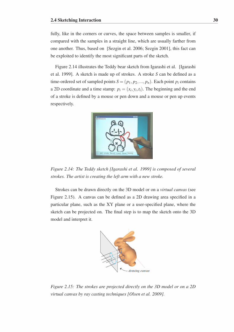
2.4 Sketching Interaction 30
fully, like in the corners or curves, the space between samples is smaller, if
compared with the samples in a straight line, which are usually farther from
one another. Thus, based on [Sezgin et al. 2006; Sezgin 2001], this fact can
be exploited to identify the most significant parts of the sketch.
Figure 2.14 illustrates the Teddy bear sketch from Igarashi et al. [Igarashi
et al. 1999]. A sketch is made up of strokes. A stroke S can be defined as a
time-ordered set of sampled points S = (p1, p2, ..., pn). Each point pi contains
a 2D coordinate and a time stamp: pi = (xi,yi, ti). The beginning and the end
of a stroke is defined by a mouse or pen down and a mouse or pen up events
respectively.
Figure 2.14: The Teddy sketch [Igarashi et al. 1999] is composed of several
strokes. The artist is creating the left arm with a new stroke.
Strokes can be drawn directly on the 3D model or on a virtual canvas (see
Figure 2.15). A canvas can be defined as a 2D drawing area specified in a
particular plane, such as the XY plane or a user-specified plane, where the
sketch can be projected on. The final step is to map the sketch onto the 3D
model and interpret it.
Figure 2.15: The strokes are projected directly on the 3D model or on a 2D
virtual canvas by ray casting techniques [Olsen et al. 2009].

2.4 Sketching Interaction 31
2.4.2 Sketch Filtering
After the process of sketch acquisition and before attempting to interpret a
sketch, it is necessary to perform some filtering. The filtering process con-
sists of reorganizing the sampled points of the stroke acquired by removing
"erroneous samples" or noise. Sezgin and Davis [Sezgin and Davis 2004]
divide the problem of noise, identifying two sources of error: user and device
error. User errors can occur when the user does not have much skill to draw
or to handle the input device, producing an inaccurate stroke. Device errors
come from an inaccurate capture of the user drawing. It is the "digitization
noise" caused by spatial and temporal quantization of the input hardware and
vary from device to device.
The spacing between samples in a natural input stroke varies from device
to device as well as with the drawing speed of the user. One way to reduce
the noise in an input stroke is to resample the data. During resampling, it is
possible to space the points regularly by discarding some closer points or by
interpolating between distant points (see Figure 2.16 left). This can be done
on the fly, or after the stroke is finished. Depending on the application needs,
linear or smooth interpolation can be used.
Figure 2.16: Filtering Operations; left: smooth uniform resampling; right: fit
to a spline curve.
After resampling data, the result still contains sample points with little
meaning. Therefore, it is common to fit them with an equivalent represen-
tation, which can be generated by a smaller set of points. Fitting the sketch
to other representation has advantages such as simplifying the input data
as well as the work of future operations and interpretations. Additionally,
many of these representations are smooth. Curve fitting is a simplification
approach that approximates the data by curves with sufficiently low average
error. Least-squares polynomial fitting [Koenig 1998] is an option, and, other
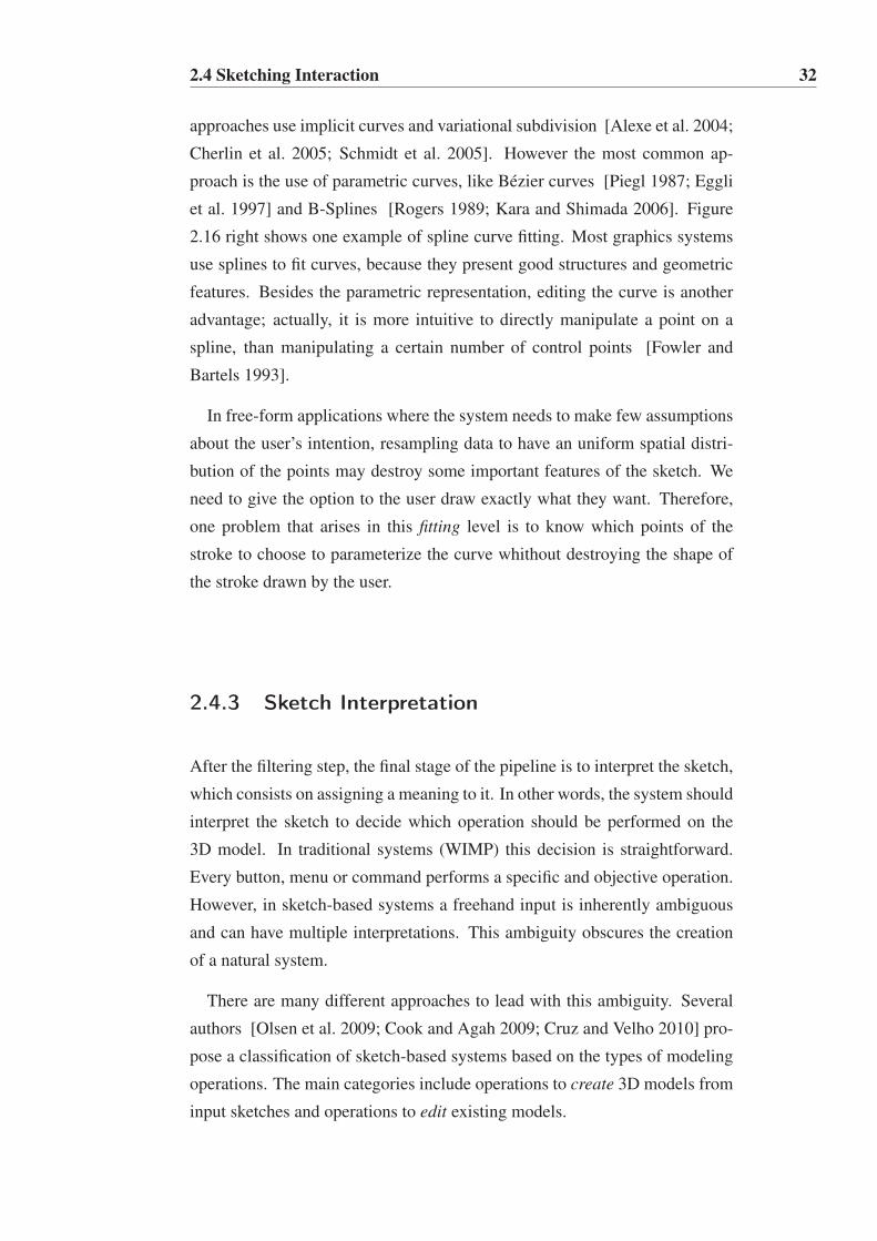
2.4 Sketching Interaction 32
approaches use implicit curves and variational subdivision [Alexe et al. 2004;
Cherlin et al. 2005; Schmidt et al. 2005]. However the most common ap-
proach is the use of parametric curves, like Bézier curves [Piegl 1987; Eggli
et al. 1997] and B-Splines [Rogers 1989; Kara and Shimada 2006]. Figure
2.16 right shows one example of spline curve fitting. Most graphics systems
use splines to fit curves, because they present good structures and geometric
features. Besides the parametric representation, editing the curve is another
advantage; actually, it is more intuitive to directly manipulate a point on a
spline, than manipulating a certain number of control points [Fowler and
Bartels 1993].
In free-form applications where the system needs to make few assumptions
about the user’s intention, resampling data to have an uniform spatial distri-
bution of the points may destroy some important features of the sketch. We
need to give the option to the user draw exactly what they want. Therefore,
one problem that arises in this fitting level is to know which points of the
stroke to choose to parameterize the curve whithout destroying the shape of
the stroke drawn by the user.
2.4.3 Sketch Interpretation
After the filtering step, the final stage of the pipeline is to interpret the sketch,
which consists on assigning a meaning to it. In other words, the system should
interpret the sketch to decide which operation should be performed on the
3D model. In traditional systems (WIMP) this decision is straightforward.
Every button, menu or command performs a specific and objective operation.
However, in sketch-based systems a freehand input is inherently ambiguous
and can have multiple interpretations. This ambiguity obscures the creation
of a natural system.
There are many different approaches to lead with this ambiguity. Several
authors [Olsen et al. 2009; Cook and Agah 2009; Cruz and Velho 2010] pro-
pose a classification of sketch-based systems based on the types of modeling
operations. The main categories include operations to create 3D models from
input sketches and operations to edit existing models.

2.4 Sketching Interaction 33
Create 3D models: Olsen et al. [Olsen et al. 2009] divide the methods
into two categories: evocative and constructive. Evocative systems start with
a sketch recognition step from a set of predefined templates, and then use the
best candidate to reconstruct the geometry. Constructive systems do not use
the recognition step and reconstruct the geometry from a sketch based only
on rules.
There are two types of evocative systems: the iconic systems and the re-
trieval systems. The first approach associates the evocative stroke to a ge-
ometric primitive [Zeleznik et al. 1996; Pereira et al. 2000; Contero et al.
2003]. A classic example is the SKETCH system of Zeleznik et al. [Zeleznik
et al. 1996], which extrapolates primitive 3D objects from a few strokes (see
Figure 2.17 left). The second approach is to retrieve template objects from a
database of predefined objects [Funkhouser et al. 2003; Fonseca et al. 2004;
Yang et al. 2005; Shin and Igarashi 2007; Lee et al. 2011; Eitz et al. 2012b]. It
associates the stroke to a more complete and complex object, instead of sim-
ple geometric primitive. A classical example of retrieval system is the Magic
Canvas [Shin and Igarashi 2007], that allows to easily build a 3D scene from
evocative strokes (see Figure 2.17 right).
Figure 2.17: Evocative Systems; left: SKETCH is a classical example of an
Iconic System [Zelezenik et al. 1996]; right: Magic Canvas is an example of
a Template Retrieval System [Shin and Igarashi 2007].
Retrieval results are purely based on geometric similarity between the in-
put sketch and the predefined object. This can help make retrieval systems
efficient as it often can be cast as a nearest-neighbor problem [Samet 2005].
However, the results can be difficult as users generally draw strokes in an ab-
stract way that is geometrically far from the predefined objects [Eitz et al.
2012a]. Therefore, retrieval systems have to rely on huge amounts of data to
offset the problem of geometric dissimilarity between sketches and predefined

2.4 Sketching Interaction 34
objects or require users to augment the sketches with text labels [Chen et al.
2009]. Using template matching to identify face parts, Dixon et al. [Dixon
et al. 2010] propose a system that helps users to get correct proportions when
sketching portraits. Lee et al. [Lee et al. 2011] build upon this idea and
developed ShadowDraw, a system that dynamically updates a shadow im-
age underlying the user’s strokes. The shadows are suggestive of object con-
tours that guide the user as they continue drawing. Their approach uses fast
nearest-neighbor matching to find geometrically similar objects and blends
those object contours into rough shadow guidelines. As with other sketch-
based retrieval systems, users must draw strokes faithfully for the retrieval to
work in the presence of many predefined objects. Consequently, users with-
out drawing skills can see no benefit from the system. Recently, Eitz and al.
[Eitz et al. 2012b] develop a system for 3D object retrieval based on 2D image
techniques (see Figure 2.18). First, they generate a set of 2D drawings for all
3D models existing in a predefined database. Then, they perform matching
between the input sketch and those 2D drawings, instead of trying to directly
match with the 3D objects. Their approach is based on a bag-of-features
(BoF) model [Squire et al. 2000; Sivic and Zisserman 2003], which has be-
come the method of choice for affine invariant image retrieval. The basic idea
of this approach is to compare images based on a histogram of features.
Figure 2.18: An example of a 3D scene with objects retrieved from a database,
built in about two minutes [Eitz et al. 2012].
Construtive Systems consist of interpreting the sketch to reconstruct a 3D
model. It has been observed that our visual system chooses to interpret draw-
ings as an object contour [Hoffman 2000]. Therefore, the majority of con-
structive sketch-based systems adopt to interpret strokes as contour lines [Eggli
et al. 1997; Igarashi et al. 1999; Alexe et al. 2004; Tai et al. 2004; Schmidt

2.4 Sketching Interaction 35
et al. 2005; Cherlin et al. 2005; Karpenko and Hughes 2006; Nealen et al.
2007]. The contour is defined as the set of the points whose normal are per-
pendicular to the view direction, dividing visible parts of the object from the
invisible. Figure 2.19 left shows an example of the contour of an object.
Figure 2.19: left: The contour of an object transmit a lot of shape informa-
tion; right: the skeleton is used to create smooths 3D objects [Olsen et al.
2009].
Teddy [Igarashi et al. 1999] and ShapeShop [Schmidt et al. 2005] are
classical examples of constructive systems based on contours. These systems
first calculate the skeleton, which is defined as the set of lines from which
the closest contour points are equidistant (see Figure 2.19 right), providing a
distance field that aids to define a 3D surface unambiguously (such that the
distance from surface to skeleton is related to the distance of contour points to
the skeleton). Based on this element, there are different approaches to recon-
struct the object’s surface. One is to rotate the points of the stroke around the
skeleton (see Figure 2.20 left). Another approach is the inflation technique,
like the one presented in Teddy (see Figure 2.20 right). Matthew Cook and
Agah [Cook and Agah 2009] present a detailed survey on sketch-based 3-D
modeling techniques.
Figure 2.20: Construtive Systems; Free form models created from contour
sketches; left: example of rotational blending surfaces [Cherlin et al. 2005];
right: example of the inflation technique used in Teddy [Igarashi et al. 1999].
To sum up, despite limited, evocative systems can produce more accurate
models from the template set than constructive systems, which can only cre-

2.4 Sketching Interaction 36
ate basic prototypes or cartoony-looking models. As Karpenko and Hughes
[Karpenko and Hughes 2006] states, a mixture of these two systems ”in which
the user’s sketch is both inflated and matched against a large database of
known forms” would be very effective.
Edit 3D models: Creating a 3D model from sketches is a difficult task and
many times conducts to a simplistic reconstruction, so to refine the geometry
of an existent model it is necessary to edit it after it is created. The editing
process can contain operations such as Augmentation [Igarashi et al. 1999;
Nealen et al. 2007; Olsen et al. 2005; Biermann et al. 2001], Cutting [Nealen
et al. 2007; Wyvill et al. 2005; Ji et al. 2006], Bending [Igarashi et al. 1999;
Kara and Shimada 2006; Cherlin et al. 2005; Wang and Markosian 2007; Ji
et al. 2006], Twisting [Kho and Garland 2005], Tunneling [Schmidt et al.
2005; Nealen et al. 2007], Oversketching [Cherlin et al. 2005; Nealen et al.
2005; Zimmermann et al. 2007], Segmentation [Ji et al. 2006; Yuan et al.
2005], Free-form Deformation [Drapper and Egbert 2003] and Affine Trans-
formations [Severn et al. 2006]. Some of these techniques are following
described.
Editing an existent model by the use of strokes typically has a straightfor-
ward and intuitive interpretation, because the 3D model serves as a reference
for mapping the strokes into its own (see Figure 2.15). A stroke is projected
onto the 3D model by ray casting techniques. After a stroke has been pro-
jected onto a 3D surface, complex details can be produced by displacing the
surface along the drawn stroke . Creating elaborated details on an existing
model is commonly known by Augmentation. Usually the surface is displaced
along the normal direction, which is appropriate for creating details like veins
(see Figure 2.21 left). Another common operation is adding new "pieces" to
the 3D model previously created (see Figure 2.21 right). Normally, it uses
constructive strokes to define the new piece along with additional strokes that
indicate the position where to connect the new piece to the original model
[Igarashi et al. 1999; Nealen et al. 2007].
Other sketch-based editing operations use the concept of Oversketching.
For example, Bending and Twisting deform an object by making a correspon-
dence between a reference stroke and a target stroke (see Figure 2.22 left).
The reference stroke is used to define the region that will be deformed and the
target stroke determines the new shape of the model. Contour oversketching

2.4 Sketching Interaction 37
Figure 2.21: "‘Augmenting"’ detail on object’s surface. left: An example that
allows to sketch extra features on the surface of the existing model [Olsen et
al. 2005]; right: An example of additive augmentation, which connects a new
piece with an existing model [Igarashi et al. 1999].
is also based on matching strokes but, in this case, the reference is a contour
automatically extracted from the model (see Figure 2.22 right).
Figure 2.22: Oversketching. left: bending a model so that a reference stroke
(red) is aligned with a target stroke (blue) [Igarashi et al. 1999]; right: con-
tour oversketching matches object’s contour (yellow) to target strokes (green)
[Nealen et al. 2005].
Sketch-based interfaces have also been explored for character animation,
using free-form sketches to specify key poses or positions in an animation
sequence [Davis et al. 2003; Thorne et al. 2004; Chen et al. 2005]. Davis et
al. [Davis et al. 2003] takes a set of figure drawings as input and generates a
character animation (see Figure 2.23). By the use of image processing tech-
niques, their system first extracts the positions of the figure joints. After that,
it applies geometrical and physical constraints to exclude improbable poses.
Finally, the 3D character model is deformed to match the sketched pose.
Instead of drawing each pose, Thorne et al. [Thorne et al. 2004] allow
the user to sketch the motion of a character (see Figure 2.24). The shape and
timing of the sketching is used to control the motion. The sketch is mapped

2.5 Facial Sketching 38
Figure 2.23: Drawn keyframes are shown together with a representation of
the final 3D animation [Davis et al. 2003].
to a set of motions predefined in a gesture vocabulary, such as walking and
jumping. The system supports a repertoire of 18 different types of motions
and combines them accordingly to the sketch. The motion is synthesized
employing a parameterized keyframe-based motion synthesis technique.
Figure 2.24: Motion Doodles. left: Gesture vocabulary; right: 2D motion
sketch and the resulting animation [Thorne et al. 2004].
The following section discusses some systems that use sketching to gener-
ate facial deformation.
2.5 Facial Sketching
Using sketching to generate 3D facial expressions has already been explored
by other researchers [Chang and Jenkins 2006; Lau et al. 2009; Sucontphunt
et al. 2008; Gunnarsson and Maddock 2010]. Facial sketching requires meth-
ods that can cope with subtle skin deformation. In contrast to sketching tech-
niques used in 3D objects, the uniqueness and the highly deformable mesh of
each face makes facial sketching so challenging. The smallest anomaly in the
face shape, proportion, skin texture or movement is immediately detected and
classified as incorrect.
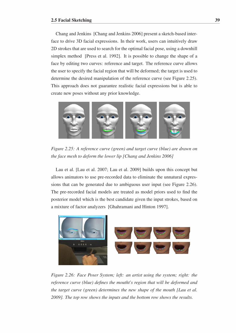
2.5 Facial Sketching 39
Chang and Jenkins [Chang and Jenkins 2006] present a sketch-based inter-
face to drive 3D facial expressions. In their work, users can intuitively draw
2D strokes that are used to search for the optimal facial pose, using a downhill
simplex method [Press et al. 1992]. It is possible to change the shape of a
face by editing two curves: reference and target. The reference curve allows
the user to specify the facial region that will be deformed; the target is used to
determine the desired manipulation of the reference curve (see Figure 2.25).
This approach does not guarantee realistic facial expressions but is able to
create new poses without any prior knowledge.
Figure 2.25: A reference curve (green) and target curve (blue) are drawn on
the face mesh to deform the lower lip [Chang and Jenkins 2006]
Lau et al. [Lau et al. 2007; Lau et al. 2009] builds upon this concept but
allows animators to use pre-recorded data to eliminate the unnatural expres-
sions that can be generated due to ambiguous user input (see Figure 2.26).
The pre-recorded facial models are treated as model priors used to find the
posterior model which is the best candidate given the input strokes, based on
a mixture of factor analyzers [Ghahramani and Hinton 1997].
Figure 2.26: Face Poser System; left: an artist using the system; right: the
reference curve (blue) defines the moutht’s region that will be deformed and
the target curve (green) determines the new shape of the mouth [Lau et al.
2009]. The top row shows the inputs and the bottom row shows the results.

2.5 Facial Sketching 40
In contrast, the method developed by Gunnarsson and Maddock [Gunnars-
son and Maddock 2010] relies on predefined reference curves in the form of
feature points (FPs), and asks the user only to sketch the target curves. Their
method uses prior knowledge in the form of a statistical model that through
a maximum likelihood approach [Tipping and Bishop 1998] analyses the
sketched strokes, maps the stroke points to the most probable FPs by Hid-
den Markov Models (HMM) and generates the final pose. This approach is
limited to be applied only in regions of the model that have predefined FPs.
Sucontphunt et al. [Sucontphunt et al. 2008] allow creating facial expres-
sions on a 3D model by manipulating the control points of a set of predefined
curves on a 2D portrait (see Figure 2.27). A prior knowledge gathered from
motion dataset is used in a hierarchical Principal Components Analysis (PCA)
model [Jolliffe 1986]. This approach guarantee realistic facial expressions
within the scope of the prior dataset but the interaction is limited to the front
view.
Figure 2.27: The 3D face (bottom row) is automatically deformed based on
the 2D portrait (top row) that is being interactively manipulated by the user
[Sucontphunt et al. 2008].
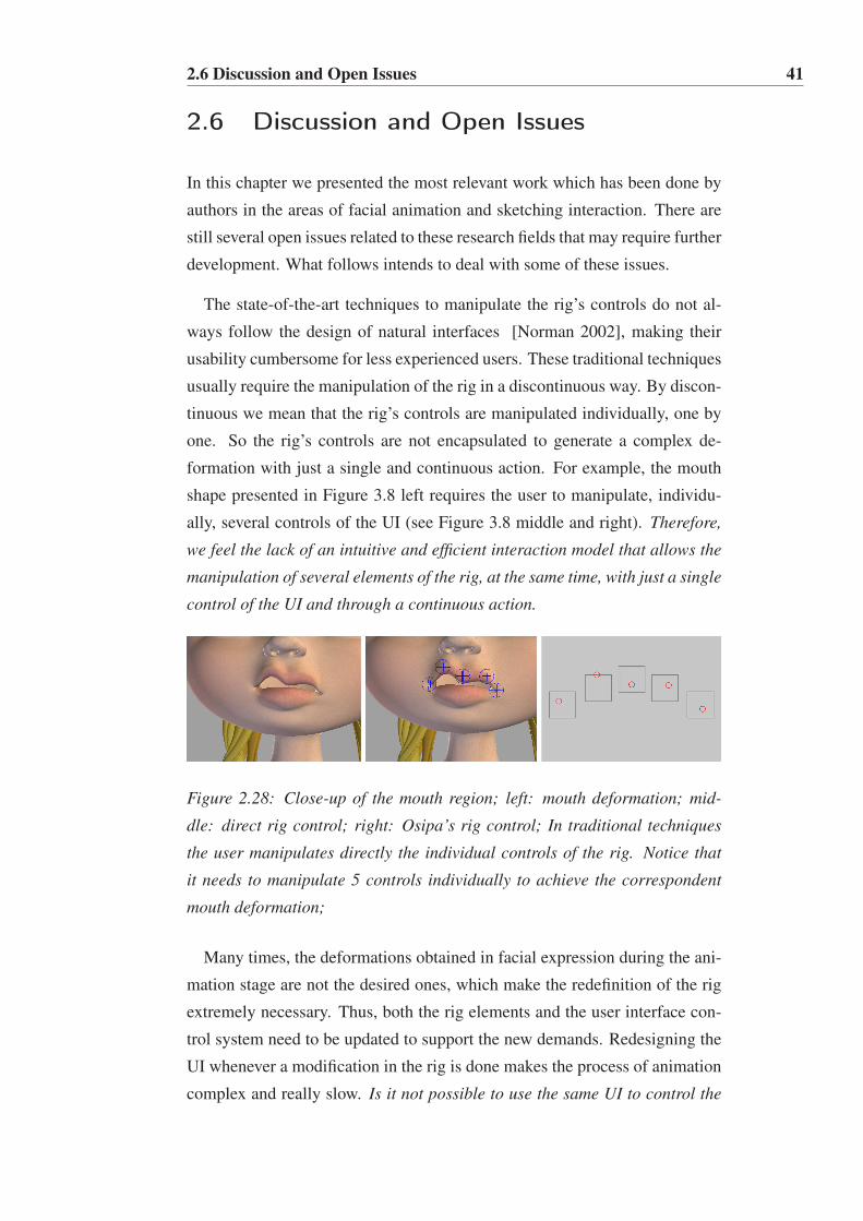
2.6 Discussion and Open Issues 41
2.6 Discussion and Open Issues
In this chapter we presented the most relevant work which has been done by
authors in the areas of facial animation and sketching interaction. There are
still several open issues related to these research fields that may require further
development. What follows intends to deal with some of these issues.
The state-of-the-art techniques to manipulate the rig’s controls do not al-
ways follow the design of natural interfaces [Norman 2002], making their
usability cumbersome for less experienced users. These traditional techniques
usually require the manipulation of the rig in a discontinuous way. By discon-
tinuous we mean that the rig’s controls are manipulated individually, one by
one. So the rig’s controls are not encapsulated to generate a complex de-
formation with just a single and continuous action. For example, the mouth
shape presented in Figure 3.8 left requires the user to manipulate, individu-
ally, several controls of the UI (see Figure 3.8 middle and right). Therefore,
we feel the lack of an intuitive and efficient interaction model that allows the
manipulation of several elements of the rig, at the same time, with just a single
control of the UI and through a continuous action.
Figure 2.28: Close-up of the mouth region; left: mouth deformation; mid-
dle: direct rig control; right: Osipa’s rig control; In traditional techniques
the user manipulates directly the individual controls of the rig. Notice that
it needs to manipulate 5 controls individually to achieve the correspondent
mouth deformation;
Many times, the deformations obtained in facial expression during the ani-
mation stage are not the desired ones, which make the redefinition of the rig
extremely necessary. Thus, both the rig elements and the user interface con-
trol system need to be updated to support the new demands. Redesigning the
UI whenever a modification in the rig is done makes the process of animation
complex and really slow. Is it not possible to use the same UI to control the

2.6 Discussion and Open Issues 42
rig, no matter what alterations are made to the initial rig?
Our research gives special attention to the creation of a sketch-based in-
teraction model to intuitively deform 3D faces. But, the uniqueness and the
highly deformable mesh of each face makes facial sketching absolutely chal-
lenging. Any inconsistency in the facial expression is easily identifiable by
the spectator, which is an expert at watching faces.
The state-of-the-art methods, based on 2D sketching, provide the users with
easy controls to generate 3D facial expressions. These methods usually allow
the user to sketch directly on the mesh. However, it is not easy to control
directly the details of a surface through a stroke drawn on the mesh and one
of the disadvantages pointed to most of the sketching systems is their lack
of accuracy [Olsen et al. 2009]. On the other hand, it is known that the
deformation of a facial model is usually achieved by manipulating the rig and
not by the direct manipulation of the mesh. Would not it be better to use
sketching to control all the elements of the rig instead of controlling directly
the vertices of the mesh?
Most facial sketching systems ask the user to sketch 2 curves: the reference
one that indicates the facial region that will be deformed and the target one
that indicates the shape of the deformation. It would be more natural and
intuitive to deform a certain region of the face with just one curve instead of
two curves. Would not it be possible to indicate both the region of the face to
be deformed and the shape of its deformation with just one curve?
Other systems allow to deform a face by manipulating specific points of a
set of predefined curves. These systems do not take advantage of the sketching
paradigm since they, actually, do not allow the user to draw strokes but just
edit curve points individually. Therefore, the discontinuity problem pointed
out to the traditional rig control interfaces remains the same.
To sum up, the main research goal of this thesis is to create complex defor-
mations on any kind of 3D face through an easy, fast and intuitive interaction
model, and still generate high quality results.

Chapter 3
Sketch Express: A Control System
for Facial Animation
To create deformations in a 3D facial model, artists usually handle the con-
trols of its underlying rig structure. Most traditional approaches allow to
manipulate the controls of the rig individually, in a discontinuous way, which
is tedious and takes a lot of time. We propose a paradigm shift in the way
the rig’s controls are manipulated. Instead of handling the controls one by
one, with our approach the artist can create complex deformations by draw-
ing free-form strokes. Therefore, it is possible to manipulate several controls
of the rig at the same time using just a single and continuous hand move-
ment. We developed a facial sketching control system that allows the artist
to draw strokes directly on the 3D mesh or on a virtual canvas. The system
is composed by four modules: Setup, Facial Posing, Pose Retargeting and
Facial Animation. These modules are integrated into Autodesk Maya, chosen
for prototyping purposes.
3.1 Problem Statement
Facial Animation is the key element to convey emotions in virtual charac-
ters. One of the major challenges in interactive systems (e.g. games, vir-
tual worlds) and off-line systems (mainly used in films) is to ensure that the

3.2 Sketch Express Approach 44
characters are highly expressive to reinforce the spectators’ "suspension of
disbelief". It is necessary to create believable facial expressions to guarantee
a correct perception of the character’s emotions [Ekman and Friesen 1971].
Creating appealing and convincing facial animations is a laborious and time-
consuming process that only expert digital artists are capable of doing. Our
research deals with the necessity of simplifying and accelerating the creation
of convincing facial expressions.
Usually, animators work with rigged 3D models. This process still involves
heavy manual work, as the artists needs to manipulate the controls of a rig
individually, in a discontinuous way, requiring them much working time to
create believable results. The rig structure can easily become impractical as
soon as the complexity of the characters and the number of expressions grow.
Also, the diversity of facial models increase the difficulty when subtle facial
details are needed, making each rig unique. Thus, the creation of an inter-
action model to intuitively manipulate the controls of a rig is not a trivial
process; however, it would be an important technical advance, since current
control systems remain unnatural.
3.2 Sketch Express Approach
This research deals with the manipulation of a facial rig. A rig can be a
simple or a complex control structure (see section 2.1.1), depending on the
movements we want to achieve in the 3D face. By requirement, the proposed
approach should allow the user to control a rig through a continuous action
and without the need of understanding its underlying structure. Furthermore,
the control system should also allow (see Figure 3.1):
• Facial Posing: the user can intuitively create facial poses from scratch,
by sketching strokes directly on the 3D mesh or on a virtual canvas.
• Facial Animation: the created poses can be interpolated resulting in real
time animations.
• Facial Retargeting: additionally, the poses can be easily transfered to
different models by storing the 2D strokes and later reusing them in
different models.

3.3 Challenges 45
The proposed system must be prepared for expert and non-expert artists
creating complex facial poses with just a freehand drawing.
Figure 3.1: Facial Sketching Control System. left: the artist can draw strokes
directly on the 3D mesh or on a virtual canvas to create facial poses; right
up: the created poses can be used to generate facial animation; right down:
one facial pose transferred from the cat-woman character to different target
characters.
The rest of the chapter describes our proposal and the main problems we
had to overcome.
3.3 Challenges
The main goal of this thesis is to create an interaction model that allows the
animation of characters’ faces on the fly. However, generating realistic face
movements is a hard work because there are many subtleties to control, such
as muscles behavior and wrinkles. Creating convincing and appealing facial
expressions requires not only a deep understanding of the incredible complex
system that lies beneath a face, but also a great knowledge of animation prin-
cipals, in order to perfectly reproduce facial movements that look realistic.
Our work gives special attention to the control interface for facial rigs. How-
ever, controlling a facial rig through sketching raises problems at two different
levels, that are discussed in the following sections:
• The facial rig control.
• The interaction model based on sketching.

3.3 Challenges 46
3.3.1 Facial Rig Control Problems
Facial animation is nowadays an important field in computer animation, con-
tinuously growing and strongly influenced by all previous body animation
research [Orvalho 2007]. However, comparing the character face with the
whole body, one can easily understand significant differences that should be
taken into account.
First, a higher number of muscles is needed to create a facial expression
more than to create a certain body pose. Moreover, the head cannot be ani-
mated with just a single joint like most parts of the body. In a face, the soft
tissue simulation needs to be more realistic to capture all the subtleties of the
facial expression. Lastly, it is not easy for an animator to achieve realistic
results and overcome the expectations of human observers, who are experts at
watching faces. It is easy for results to fall into the creepy appearance cate-
gory known as the Uncanny Valley, first introduced by Masahiro Mori [Mori
1970]. Therefore, facial animation requires much more attention than body
animation to obtain a lifelike response.
To obtain realistic results in facial animation, it is necessary to use a larger
variety of deformers to simulate the soft tissue and muscles, to assign a greater
number of joints to influence specific parts of the face and to implement a
higher number of controls to manipulate the whole head structure and sec-
ondary face regions. Thus, to obtain good animations, it is necessary to have
a facial rig with the right controls to reproduce any subtle movement of the
face.
The manipulation of the rig controls is not, however, an easy task. Nowa-
days systems used to control facial rigs present some technological problems:
• Many rig controls: when defining a rig, artists tend to add many con-
trols to handle every region of the face and reproduce the subtleties of
each expression. Typically, they use macro-controls to manipulate ma-
jor muscular groups that involve the whole face in large facial move-
ments, and micro-controls for subtle movement that often appear only
in one region of the face, such as the brows, eyelids or lips [Holly
2006]. When the number of micro and macro controls increases the
process of rigging becomes difficult to master because there are an ex-

3.3 Challenges 47
cessive number of controls to handle. Thus, encapsulating a set of rig
controls on a single control usually simplifies the rigging process but
presents a particularly challenging problem.
• Discontinuous rig control: generally, to handle facial rigs most sys-
tems require the manipulation of the rig controls in a discontinuous
way, which means that the controls are handled one by one. Manip-
ulating all the rig controls individually makes the process of rigging
control time-consuming and difficult to master, specially in the regions
of the face composed by many rig elements. However, handling several
rig elements at the same time through a continuous action presents a
challenging problem.
• UI complexity: typically, the interface to manipulate a rig is cumber-
some because there are a lot of controls to handle. These rig’s controls
needs to be efficiently organized on the UI to become the usability nat-
ural and intuitive. Therefore, designing a rig’s UI that intuitively maps
the manipulation of the controls to the model deformation is extremely
challenging.
3.3.2 Sketching Problems
Currently, sketch-based systems have undergone major developments. How-
ever, there still are some important challenges to be solved in this domain.
Based on previous research [Olsen et al. 2009; Cook and Agah 2009; Cruz
and Velho 2010], we present below some important open problems:
• Drawing interpretation: sketching is a natural and fast process for trans-
mitting ideas. However, interpreting a sketch is not a simple task and
ambiguity problems may be encountered. This is due to the fact that a
stroke can have multiple interpretations. Therefore, the ambiguity prob-
lem inherent to freehand input is very challenging for ongoing research.
• Lack of precision: traditional WIMP interfaces, which uses a control-
point paradigm, allows to accurately select and modify directly a sur-
face vertex. On the other hand, sketch-based interfaces lose precision
when trying to manipulate a 3D model, because they do not directly

3.4 Sketch Express Overview 48
control the details of the surface. To enforce accurate precision in
sketch-based systems it is normal to specify and infer geometric con-
straints. While mix input sketches with constraints is typical in engi-
neering design systems [Jorge et al. 2003; Pereira et al. 2004; Contero
et al. 2005], the same is not so common in other application areas, like
free-form design systems. The meaning of a free-form stroke is hard
to predict and, consequently, difficult to define geometric constraints.
In these kind of applications, the geometric precision is less important
than allowing the artist to create free-form strokes from freehand input
and the precision is usually sacrificed in favor of the simplicity of the
interface.
• User interface: One of the goals of sketch-based systems is to provide
a natural interface that imitates the feeling of the traditional pencil and
paper drawing. However, most sketch-based interfaces are far from
being natural - many require the user to draw in very specific ways in
order to function properly, which reduces the immersion and ease of
use. Also, the fact of wanting such a clean interface can lead us to
the problem of self-disclosure - when an interface does not disclose
any hints about how to use it - raised by LaViola and Joseph [LaVi-
ola 2006]. Therefore, designing sketch-based systems with the correct
combination of algorithmic and interface elements is a large challenge
for ongoing research.
3.4 Sketch Express Overview
The system we propose implements a method that is independent of the un-
derlying rig structure, being able to work with simple and complex rigs. We
define a user interaction model that eases the control process of a 3D face
based on a new approach (see figure 3.2).
The user can directly interact with the sketch-based User Interface tool
(UI). The UI tool is represented by a sketching area where the artist can draw
strokes to, consequently, create facial poses. The rig stores the control struc-
ture created by the artist. The UI tool is mapped to the rig using our sketching
control method, which we call SKC. The SKC method applies a 3D geometric

3.4 Sketch Express Overview 49
Figure 3.2: User Interaction Model
transformation on the rig structure based on the shape of the strokes drawn
on the sketching area of the UI tool. The geometric transformation activated
on the rig by the drawn strokes will correspond to the deformation of the 3D
model. The user receives visual feedback of the deformation in a 3D viewport
window.
Figure 3.3 shows an overview of the system pipeline and illustrates the
facial sketching workflow.
We start with a rigged 3D facial mesh that is divided in several regions. The
mesh is the external geometry of the 3D model. It uses a polygonal surface
composed by a set of vertex and a topology that connects them. The rig is a
highly deformable structure of a face and is created manually by an artist. The
rig can be defined by several elements: joints, shapes, deformable objects and
constraints. It is the responsible for triggering the deformation on the mesh.
The regions represent specifics areas of the face, such as the brows, eyes,
nose, cheeks or mouth. A region is defined as a set of rig elements (joints, for
the sake of the explanation), which are manipulated by a stroke (see Figure
3.4).
There is an initial setup step to allow the user to define the facial regions
that will be deformed. In the case of the UI tool to be composed by several
canvases, the user needs to associate the defined regions to the corresponding
canvases. The setup information ensures the mapping between the strokes
will be drawn on the sketching area of the UI tool and the elements of the rig.
Besides the setup stage, the regions can also be defined in real time during the
sketching process.
After the setup step the 3D model is ready for the creation of facial expres-

3.4 Sketch Express Overview 50
Figure 3.3: System Pipeline. Shows the main steps needed to create, animate
and retarget facial poses with our facial sketching control system.
sions - posing. The user draws free-form strokes on the sketching area and the
system automatically creates the deformation on the correspondent region of
the 3D face, by the SKC method. The UI tool allows the user to draw strokes
directly on the 3D mesh or on a virtual canvas. The user can indefinitely refine
the strokes and save poses at anytime.
The created facial poses can then be used as keyframes for animation or
transferred for different characters, by a retargeting technique. In this way,
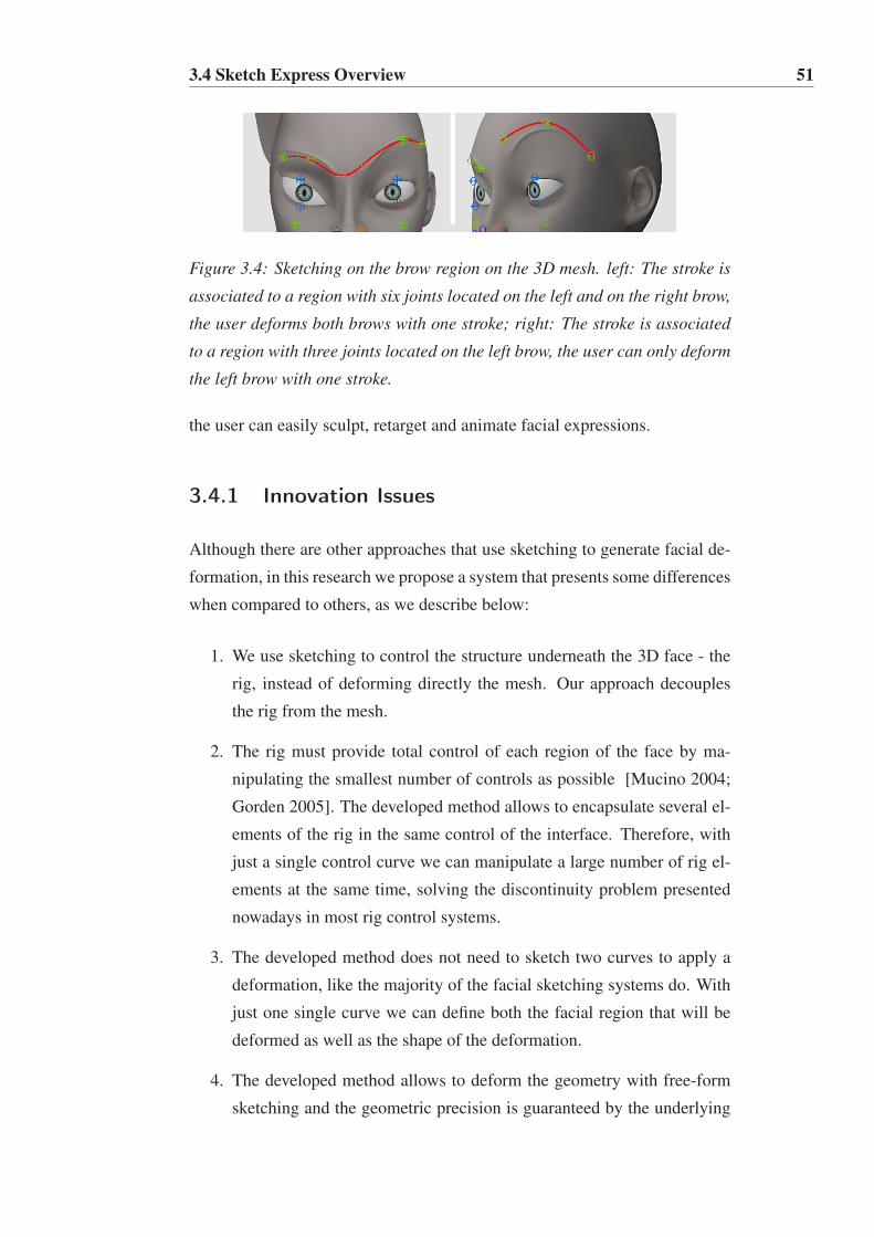
3.4 Sketch Express Overview 51
Figure 3.4: Sketching on the brow region on the 3D mesh. left: The stroke is
associated to a region with six joints located on the left and on the right brow,
the user deforms both brows with one stroke; right: The stroke is associated
to a region with three joints located on the left brow, the user can only deform
the left brow with one stroke.
the user can easily sculpt, retarget and animate facial expressions.
3.4.1 Innovation Issues
Although there are other approaches that use sketching to generate facial de-
formation, in this research we propose a system that presents some differences
when compared to others, as we describe below:
1. We use sketching to control the structure underneath the 3D face - the
rig, instead of deforming directly the mesh. Our approach decouples
the rig from the mesh.
2. The rig must provide total control of each region of the face by ma-
nipulating the smallest number of controls as possible [Mucino 2004;
Gorden 2005]. The developed method allows to encapsulate several el-
ements of the rig in the same control of the interface. Therefore, with
just a single control curve we can manipulate a large number of rig el-
ements at the same time, solving the discontinuity problem presented
nowadays in most rig control systems.
3. The developed method does not need to sketch two curves to apply a
deformation, like the majority of the facial sketching systems do. With
just one single curve we can define both the facial region that will be
deformed as well as the shape of the deformation.
4. The developed method allows to deform the geometry with free-form
sketching and the geometric precision is guaranteed by the underlying

3.5 Sketching Control Method 52
rig. We provide a stable interaction, in which the system is able to
detect erroneous input strokes and automatically fix them to a "‘possi-
ble"’ stroke. It does not mean that the stroke corrected by the system
will produce the desired deformation, but it will surely produce a pos-
sible deformation for the defined rig. The potentiality of the method to
work on the top of the rig decreases the ambiguity problem presented
by many sketch-based systems.
5. The quality of the deformations to be achieved with our system depends
on the rig quality. Therefore, if the rig quality is low, our method will
still succeed, although the results of the deformation may not be satis-
factory.
6. The approach we propose is not limited to a set of predefined curves
with control points. Instead, our sketching method allows the user to
draw continuously free-form strokes and change the stroke at any point,
resulting in facial deformation on the fly.
7. The rig and the control interface often need to be updated to support new
deformations. With our approach, the control interface always remains
the same despite the modifications of the underlying rig. In this case,
it will be just necessary to redefine the regions, accordingly to the new
rig.
3.5 Sketching Control Method
For each stroke the user draws on the sketching area of the UI tool, the SKC
method generates a NURBS curve. Then, it associates the curve to the corre-
sponding region of the 3D model, causing a deformation of the 3D mesh.
The following section explains the main concepts related to the sketching
representation and respective curve fitting.
3.5.1 Sketching Representation
We define a stroke S as an ordered set of points {s0, ..,sn−1}, which is drawn
on the sketching area of the UI tool. Each stroke S is stored as a parametric
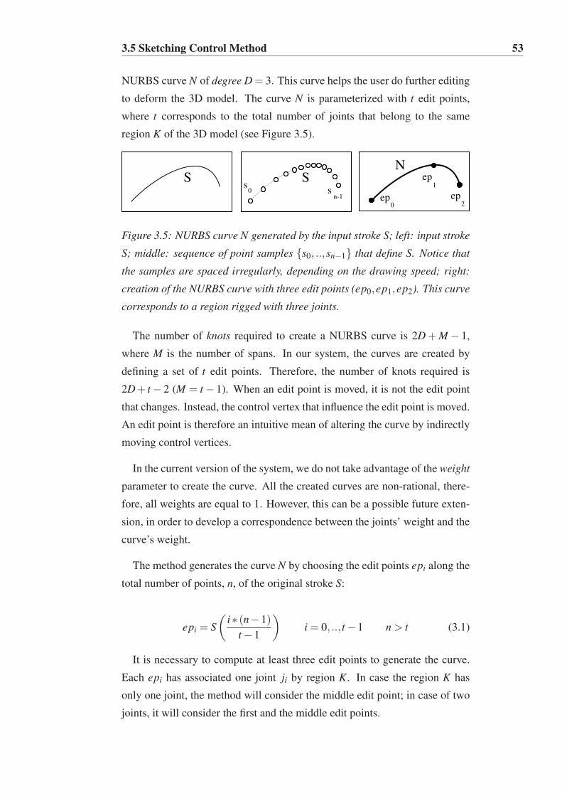
3.5 Sketching Control Method 53
NURBS curve N of degree D = 3. This curve helps the user do further editing
to deform the 3D model. The curve N is parameterized with t edit points,
where t corresponds to the total number of joints that belong to the same
region K of the 3D model (see Figure 3.5).
SN
ep0
ep1
ep2
Ss
0 sn-1
Figure 3.5: NURBS curve N generated by the input stroke S; left: input stroke
S; middle: sequence of point samples {s0, ..,sn−1} that define S. Notice that
the samples are spaced irregularly, depending on the drawing speed; right:
creation of the NURBS curve with three edit points (ep0,ep1,ep2). This curve
corresponds to a region rigged with three joints.
The number of knots required to create a NURBS curve is 2D+M − 1,
where M is the number of spans. In our system, the curves are created by
defining a set of t edit points. Therefore, the number of knots required is
2D+ t − 2 (M = t − 1). When an edit point is moved, it is not the edit point
that changes. Instead, the control vertex that influence the edit point is moved.
An edit point is therefore an intuitive mean of altering the curve by indirectly
moving control vertices.
In the current version of the system, we do not take advantage of the weight
parameter to create the curve. All the created curves are non-rational, there-
fore, all weights are equal to 1. However, this can be a possible future exten-
sion, in order to develop a correspondence between the joints’ weight and the
curve’s weight.
The method generates the curve N by choosing the edit points epi along the
total number of points, n, of the original stroke S:
epi = S
(
i∗ (n−1)t −1
)
i = 0, .., t −1 n > t (3.1)
It is necessary to compute at least three edit points to generate the curve.
Each epi has associated one joint ji by region K. In case the region K has
only one joint, the method will consider the middle edit point; in case of two
joints, it will consider the first and the middle edit points.

3.5 Sketching Control Method 54
We do not resample the points of the original stroke S because we want to
take advantage of the natural way of drawing. As it was already mentioned in
Section 2.4.1, the points of S become irregularly spaced, since the user does
not naturally draw with the same speed (see Figure 3.6 left). Thus, as shown
in Figure 3.6 right, smoothing the original points to have an uniform spatial
redistribution can destroy the shape of the stroke drawn by the user.
S
N
S
N
s0
sn-1
sn-1
2
s0
sn-1
sn-1
2
Figure 3.6: Curve fitting; the input stroke S (dashed line) and the curve N
generated with t = 3 edit points (full line) computed through the Equation
3.1; left: without resampling; right: with resampling; Notice that the fit-
ting without resampling generated a curve with the shape closer to the input
stroke.
The fact that the curve N is parameterized with the same number of joints
that belong to the region K allows a stroke S badly drawn by the user to be
automatically "corrected"’ by the system (see Figure 3.7). It means that the
SKC method will adapt the stroke drawn by the user to the rig defined by the
artist, diminishing, in this way, the problem of ambiguity presented by most
of the sketch-based systems.
S
NN
S S
Figure 3.7: Curve generated by the system from an erroneous stroke drawn
by the user; left: erroneous stroke S; middle: the curve N corresponds to a
region rigged with three joints; right: the curve N corresponds to a region
rigged with five joints.
Figure 3.8 shows two strokes around the mouth converted into two NURBS,
and the resulting deformation on the face model. It is worth to highlight the
advantage of manipulating several joints simultaneously just with a simple
stroke. By doing it, the problem of discontinuity presented by many rig con-
trol systems is solved.

3.5 Sketching Control Method 55
Figure 3.8: Close-up of the mouth region. Notice how the mouth deformation
are accordingly to the shape of strokes; left: two strokes around the mouth;
the NURBS of up stroke created with 5 epi because the mouth up region has
5 joints; the NURBS of down stroke has 3 epi because the mouth down region
was rigged with 3 joints; right: correspondent mouth deformation.
The SKC method developed in this thesis allows to manipulate a rig struc-
ture through simply 2D sketching. As the user can draw strokes directly on
the 3D mesh or on a virtual canvas, we divide the SKC method in two com-
ponents:
• Sketching on the 3D mesh, to compute the geometric transformation of
the rig elements based on the shape of the strokes drawn directly on the
3D mesh.
• Sketching on the virtual canvas, to compute the geometric transforma-
tion of the rig elements based on the shape of the strokes drawn on the
virtual canvas.
3.5.2 Sketching on the 3D Mesh
The user draws a stroke S directly on the mesh to control a certain region K
of the 3D model.
The method begins by duplicating the original 3D mesh. We name the
original mesh Active mesh Am and the duplicate Reference mesh Rm. We
hide Rm and use it only as a local coordinate reference. The mesh that will be
deformed is Am.
The method performs ray casting with the stroke to choose the closest
points on the Reference mesh Rm (see Figure 3.9).
For each stroke drawn on the mesh Rm, the method updates the joints’ po-
sitions of the respective region K of the 3D model. To know which region K
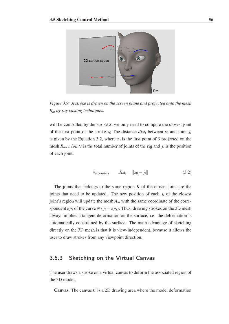
3.5 Sketching Control Method 56
Figure 3.9: A stroke is drawn on the screen plane and projected onto the mesh
Rm by ray casting techniques.
will be controlled by the stroke S, we only need to compute the closest joint
of the first point of the stroke s0 The distance disti between s0 and joint ji
is given by the Equation 3.2, where s0 is the first point of S projected on the
mesh Rm, nJoints is the total number of joints of the rig and ji is the position
of each joint.
∀i<nJoints disti = ‖s0 − ji‖ (3.2)
The joints that belongs to the same region K of the closest joint are the
joints that need to be updated. The new position of each ji of the closest
joint’s region will update the mesh Am with the same coordinate of the corre-
spondent epi of the curve N ( ji = epi). Thus, drawing strokes on the 3D mesh
always implies a tangent deformation on the surface, i.e. the deformation is
automatically constrained by the surface. The main advantage of sketching
directly on the 3D mesh is that it is view-independent, because it allows the
user to draw strokes from any viewpoint direction.
3.5.3 Sketching on the Virtual Canvas
The user draws a stroke on a virtual canvas to deform the associated region of
the 3D model.
Canvas. The canvas C is a 2D drawing area where the model deformation

3.5 Sketching Control Method 57
can be sketched on. There are two types of canvas: 2D canvas and 2.5D can-
vas. The 2D canvas is predefined on the UI and it has a fixed position, size and
orientation. The 2.5D canvas is a dynamic screen-aligned billboard created
in runtime, always perpendicular to the user viewpoint direction [Akenine-
Möller et al. 2008]. The shape and position of a stroke affects the associated
rig elements in the 3D model. Thus, the combination of stroke and canvas
becomes the effective controller of a region of the 3D model. This model is a
3D face displayed on a separate area, which we call deformation space B.
Deformation Space. The deformation space B shows, in real time, the cor-
respondent deformation of the 3D model. To compute the deformation space
B, we calculate the minimum bounding space of the actual joints position,
obtaining the minimum and maximum position values r0 and r1 (see Figure
3.10 first row).
Figure 3.10: Deformation Space B; first row: deformation space B where the
joints movement take place, the initial position of the joints are represented
by highlighted circles; The value d represents the displacement to expand the
deformation space; second row: close-up of the mouth region with different d
values on the xy coordinate; Notice that the deformation space increases from
left to right.
To allow the joints to move "outward" of their actual position, but also to
support exaggeration of deformations, we expand the space by a displacement
value d. This value is initialized by the system, but also can be updated by the
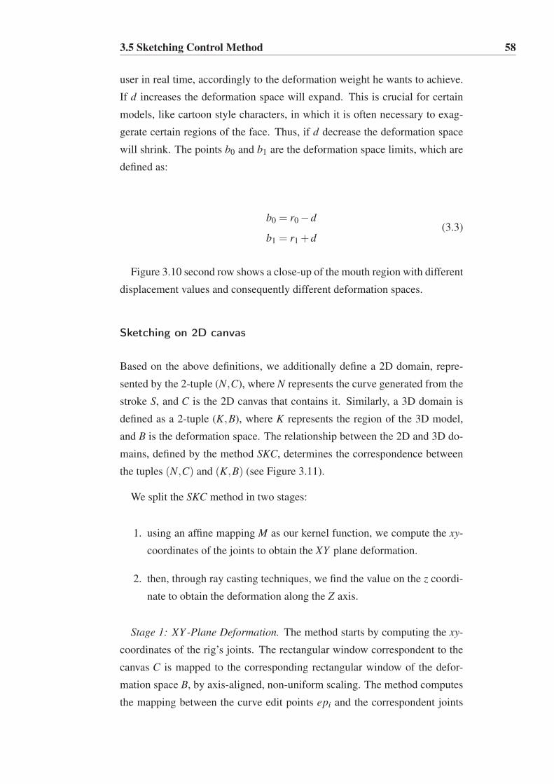
3.5 Sketching Control Method 58
user in real time, accordingly to the deformation weight he wants to achieve.
If d increases the deformation space will expand. This is crucial for certain
models, like cartoon style characters, in which it is often necessary to exag-
gerate certain regions of the face. Thus, if d decrease the deformation space
will shrink. The points b0 and b1 are the deformation space limits, which are
defined as:
b0 = r0 −d
b1 = r1 +d(3.3)
Figure 3.10 second row shows a close-up of the mouth region with different
displacement values and consequently different deformation spaces.
Sketching on 2D canvas
Based on the above definitions, we additionally define a 2D domain, repre-
sented by the 2-tuple (N,C), where N represents the curve generated from the
stroke S, and C is the 2D canvas that contains it. Similarly, a 3D domain is
defined as a 2-tuple (K,B), where K represents the region of the 3D model,
and B is the deformation space. The relationship between the 2D and 3D do-
mains, defined by the method SKC, determines the correspondence between
the tuples (N,C) and (K,B) (see Figure 3.11).
We split the SKC method in two stages:
1. using an affine mapping M as our kernel function, we compute the xy-
coordinates of the joints to obtain the XY plane deformation.
2. then, through ray casting techniques, we find the value on the z coordi-
nate to obtain the deformation along the Z axis.
Stage 1: XY -Plane Deformation. The method starts by computing the xy-
coordinates of the rig’s joints. The rectangular window correspondent to the
canvas C is mapped to the corresponding rectangular window of the defor-
mation space B, by axis-aligned, non-uniform scaling. The method computes
the mapping between the curve edit points epi and the correspondent joints
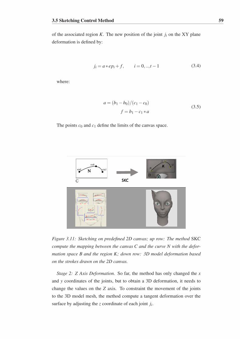
3.5 Sketching Control Method 59
of the associated region K. The new position of the joint ji on the XY plane
deformation is defined by:
ji = a∗ epi + f , i = 0, .., t −1 (3.4)
where:
a = (b1 −b0)/(c1 − c0)
f = b1 − c1 ∗a(3.5)
The points c0 and c1 define the limits of the canvas space.
Figure 3.11: Sketching on predefined 2D canvas; up row: The method SKC
compute the mapping between the canvas C and the curve N with the defor-
mation space B and the region K; down row: 3D model deformation based
on the strokes drawn on the 2D canvas.
Stage 2: Z Axis Deformation. So far, the method has only changed the x
and y coordinates of the joints, but to obtain a 3D deformation, it needs to
change the values on the Z axis. To constraint the movement of the joints
to the 3D model mesh, the method compute a tangent deformation over the
surface by adjusting the z coordinate of each joint ji.

3.5 Sketching Control Method 60
The tangent deformation is based on ray casting, and it is an adjustment
over the reference mesh Rm (see Figure 3.12). In Am, the joint j is moved
from its initial position j0 to position j1 by the affine mapping M. To change
the joint coordinate and get to the final joint position over the Rm, the method
calculates the auxiliary point paux in front of the mesh by adding the joint
position j1 to the normal vector on the mesh~n:
paux = j1 +~n (3.6)
Then, it casts a ray~r from paux in the inverse normal direction. The inter-
section point between~r and Rm is j2, the final position of the joint with the
xyz coordinate computed.
Figure 3.12: Tangent deformation over the surface; first row: close up of
the mouth region; second row: 2D representation of the deformation steps;
left: j0 is the initial position of the joint; middle: j1 is the position after the
mapping M, which is not tangent to Rm; right: the final joint position j2 is
calculated according to j1, normal vector~n, point paux and the ray~r cast from
it.
The 2D canvas configuration is view-dependent. Thus, the only control-
lable re-posing action is a translation orthogonal to a fixed viewing plan, fol-
lowed by automated depth tweaks. The user cannot rotate the camera to apply,
for example, deformations that come out the mesh, like bulges. To overcome
this limitation and to allow the creation of "non-tangent" deformations, it was
created another type of canvas: the 2.5D billboard canvas.

3.5 Sketching Control Method 61
Sketching on 2.5D canvas
The user draws strokes S on a 2.5D canvas to deform the associated region of
the 3D model. The user interaction takes place on a 3D space, where the 3D
model is located. There are no predefined canvas like in the sketching on 2D
canvas.
The 2.5D billboard canvas can be created in two different ways:
• by the user, which can place the 2.5D canvas in any position of the 3D
scene at any time; In this case, the created canvas needs to be associated
to the region K that the user intends to deform.
• automatically by the system, when the system recognizes that a stroke
comes out of the mesh; In this case, the new canvas is immediately
associated to the same region K of that stroke.
We extended the affine mapping M by computing a transformation between
two bounded boxes in 3D space, instead of computing a transformation be-
tween two 2D rectangular windows. The upper row of Figure 3.13 shows the
canvas bounding box that is mapped to the correspondent deformation space
bounding box.
Figure 3.13: Sketching on 2.5D canvas; upper row: the method SKC compute
the mapping between the bounding box C and the curve N with the deforma-
tion space B and the region K; lower row: deformation of the cheek and nose
using a 2.5D canvas.

3.5 Sketching Control Method 62
Any stroke on the 2.5D canvas will imply a 3D deformation in a parallel
direction to the canvas plane (see Figure 3.13, lower row). The principal rea-
son of the 2.5D canvas is to allow the user to create non-tangent deformations,
like the bulges showed in the figure. In these situations, it is not necessary to
constrain the movement of each joint ji to the 3D mesh and the stage 2 of the
SKC method is not necessary to be executed.
Figure 3.14 illustrates the possibility of applying the same displacement to
several joints of the same region K. To compute the displacement vector ~d,
we only consider the midpoint epi of two successive curves N j and N j+1:
~d = ep(i,N j+1)− ep(i,N j)(3.7)
Finally, ~d is applied to all the joints that belong to the region K:
ji = ji + ~d (3.8)
Figure 3.14: Displacement of the joints of the mouth region. left: joints posi-
tion defined by N j; right: joints position defined by N j+1 after a displacement
was applied to each joint. Notice thal all the joints of the mouth moved in the
same direction of the displacement vector ~d.

3.6 Sketch Express Framework 63
3.6 Sketch Express Framework
We use the SKC method to build a sketching control system for facial anima-
tion. We developed two different interaction models:
• 2D Sketching Interface, which allows the user to draw strokes on a fixed
2D canvas (see Section 3.5.3).
• 3D Sketching Interface, which allows the user to draw strokes on both
the 3D mesh (see Section 3.5.2) and the 2.5D canvas (see Section 3.5.3).
The system is implemented in C++ as a plug-in for Maya, chosen for pro-
totyping purposes. It is composed by four modules: Setup, Facial Posing,
Facial Animation and Facial Retargeting, that are described in the following
sections.
3.6.1 Setup
Figure 3.15: Setup Module Overview.
This is the initial step, where the user defines the regions of the rig model
(see Figure 3.15 right), which will be manipulated by strokes. In the case
of the 2D sketching interface, the defined region also needs to be associated
to the corresponding canvas of the UI tool (see Figure 3.15 left). We have
implemented a wizard interface to assist the user on the setup process, hiding
the complexity of 3D modeling and animation. The wizard is prepared so
novice users can also configure the system. Additionally, the defined regions
can be saved in a XML setup file (see Figure 3.15 middle). Thus, characters
with a similar rig can use the same file. For example, in a production with 10
different characters that share the same rig, the setup needs to be performed

3.6 Sketch Express Framework 64
only once. For a new character with a different rig, we either do the setup
process or apply a rig retargeting technique [Orvalho 2007; Komorowski
et al. 2010] and then apply the stored setup file. The character of the Figure
3.15 has 25 joints and it took about one minute to setup the rig to the 11
canvas. After the setup step, the 3D model is ready for the creation of facial
poses and animation.
3.6.2 Facial Posing
To create a pose the user needs to deform the face model. Deforming the mesh
of the face model is a very straightforward and interactive process. First, the
user draws a stroke on the drawing area of the UI tool. Then the stroke is
mapped into the 3D model, which automatically deforms the correspondent
facial region of the character. The user can continue drawing strokes to inter-
actively sculpt poses. The user can also modify an existent stroke (totally or
partially) and adjust the shape of the mesh in real-time.
The user starts by deciding which sketching interface to use: 2D Sketching
Interface or 3D Sketching Interface.
2D Sketching Interface. Sketching on a 2D Canvas neatly maps the mental
concept of a face as a collection of parts. Each part is a facial region, such
as, the brows, eyes, nose, cheeks and mouth. We start with a sketching area
located in the 3D space. This drawing area is composed of several canvases,
which are depicted as boxes on the background generic face image (see Figure
3.16 left).
Figure 3.16: 2D Sketching Interface; left: 3D model deformation based on
the strokes drawn on the 2D canvas; right: two examples of how the user can
draw the strokes guided by the background image.
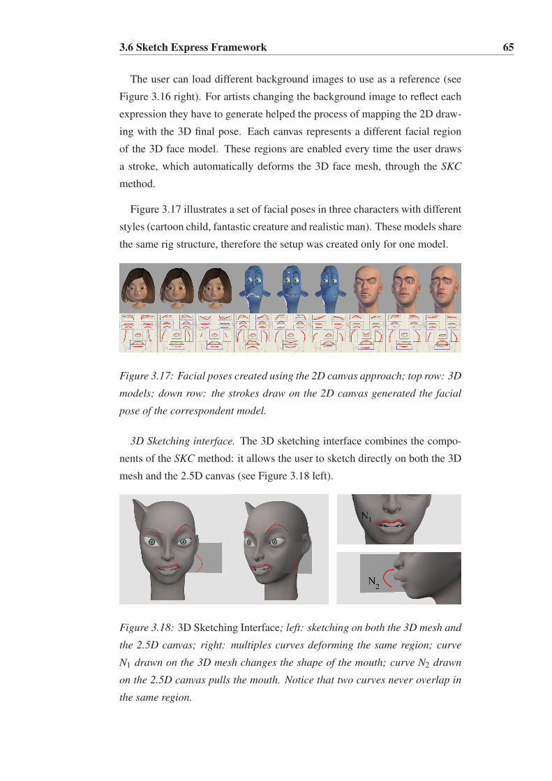
3.6 Sketch Express Framework 65
The user can load different background images to use as a reference (see
Figure 3.16 right). For artists changing the background image to reflect each
expression they have to generate helped the process of mapping the 2D draw-
ing with the 3D final pose. Each canvas represents a different facial region
of the 3D face model. These regions are enabled every time the user draws
a stroke, which automatically deforms the 3D face mesh, through the SKC
method.
Figure 3.17 illustrates a set of facial poses in three characters with different
styles (cartoon child, fantastic creature and realistic man). These models share
the same rig structure, therefore the setup was created only for one model.
Figure 3.17: Facial poses created using the 2D canvas approach; top row: 3D
models; down row: the strokes draw on the 2D canvas generated the facial
pose of the correspondent model.
3D Sketching interface. The 3D sketching interface combines the compo-
nents of the SKC method: it allows the user to sketch directly on both the 3D
mesh and the 2.5D canvas (see Figure 3.18 left).
Figure 3.18: 3D Sketching Interface; left: sketching on both the 3D mesh and
the 2.5D canvas; right: multiples curves deforming the same region; curve
N1 drawn on the 3D mesh changes the shape of the mouth; curve N2 drawn
on the 2.5D canvas pulls the mouth. Notice that two curves never overlap in
the same region.

3.6 Sketch Express Framework 66
The user interaction takes place on the 3D space, where the 3D model is
located and there are no predefined drawing area like in the 2D Sketching
interface. The 2.5D billboard canvas is created on the fly and the user can
draw strokes from any camera orientation, which facilitates the work around
the 3D space.
In Figure 3.18 right, we show an example of multiple curves deforming the
same region. Notice that there is only one curve visible in the mouth region at
each time. When the user sketches a new stroke the previous curve is deleted
to avoid that the curves overlap in the same region.
Figure 3.19 compares the sketching interface modes: direct drawing over
a 3D mesh, 2D and 2.5D sketching on a canvas. The results show the pos-
sibility of using the 2.5D approach, like bulges in the face or stylized and
cartoonist noses (such as Pinocchio’s), which are not possible in the 2D ap-
proach. It also demonstrate how it is possible to draw strokes directly on a
3D face model and still maintain the morphology of the face. This is feasible
because the movements are constrained by the mesh, avoiding the geometry
to do unexpected deformations outside the 3D face model. Combining the 3D
direct manipulation and the 2.5D canvas allows to go around the limitations
associated to the 2D canvas interface.
Figure 3.19: Comparison of facial poses using the different UI configurations
of our sketching method. The box with an X means that the expression is not
possible to achieve with that UI configuration; right: two facial examples us-
ing the 2D canvas interface and combining 2.5D canvas and direct sketching
over the 3D mesh.

3.6 Sketch Express Framework 67
3.6.3 Facial Animation
As an add-on to our sketching system we allow the user to create facial an-
imations using the traditional keyframe technique. Our system is designed
having in mind the usability and direct manipulation. After creating all the
facial poses the user is able to generate animations by interpolation of poses.
Figure 3.20 shows a few frames of a facial animation sequence obtained using
our sketching system and generated with off-line render.
Figure 3.20: Keyframes extracted from a video sequence to show different
poses created using our method; final results generated with an off-line ren-
der.
3.6.4 Facial Retargeting
By facial retargeting we mean the action of transferring the facial pose from
a source to a target model. The mesh topologies of both source and target
models can be different but the rig structure must be the same.
In our system to retarget facial poses we store, in a pose file, the strokes
the user draw in the canvases (see Figure 3.21). For each stroke drawn on
the canvas, we save the edit points epi used to generate the curve N, and the
displacement value d used to compute the deformation space B (see Section
3.5.3). Then, these data can be reused in different characters as long as they
share the same rig. After the curves are loaded into the new 3D model the
user can use the sketching tool to delete, modify and re-draw the curves to

3.6 Sketch Express Framework 68
create new poses, or simply modify the d value to adjust the weight of the
deformation.
Figure 3.21: Retargeting from a source model to different target models. No-
tice that the characters have different facial proportions and styles.
Figure 3.22 illustrates the retargeting of facial poses between different mod-
els. The first column shows the strokes in the canvases; column 2 shows the
source model with the pose created with the strokes from column 1, while
columns 3 to 7 show the result of the retargeting process. Each row rep-
resents a different source model and shows how the retargeting results vary
between characters but retain consistency. Notice that when the source and
target characters have similar facial proportions the retargeting result is ac-
curate. However, if the facial proportions vary significantly, the retargeting
process may produce exaggerated deformations. Figure 3.22 row 4 shows
an example of how the deformation in the mouth breaks for extreme poses.
The user can fix the pose by modifying the curves or simply by adjusting the
displacement value d (see Figure 3.22 row 5).
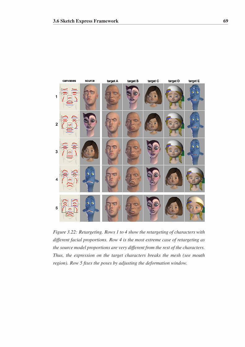
3.6 Sketch Express Framework 69
Figure 3.22: Retargeting. Rows 1 to 4 show the retargeting of characters with
different facial proportions. Row 4 is the most extreme case of retargeting as
the source model proportions are very different from the rest of the characters.
Thus, the expression on the target characters breaks the mesh (see mouth
region). Row 5 fixes the poses by adjusting the deformation window.

Chapter 4
Results and Validation
The facial sketching control system developed in this research was validated
with a series of experiments. We made several computations in order to quan-
tify the user’s effort and the time the user took to create a pose. To evaluate
if the poses created can be automatically transferred to different models we
tested the precision of our retargeting method. We also underwent tests to
measure the response time of the system. The 3D facial models used during
the experiments were created by artists, who have supervised the results and
provided valuable feedback to improve the workflow of the system. The results
from our research also were applied in the psychotherapy field. The developed
sketching method is implemented in a serious game context, where the goal is
to teach people with autism to recognize emotions from facial expressions. At
the end of this chapter, you can verify that the proposed approach allows to
produce facial expressions in an easy, fast and intuitive way.
4.1 Introduction
Central to the research work presented in this document is the validation step,
since we need to know if our sketching approach is a valid method to create
facial expressions. The work includes two different interaction models to cre-
ate facial expressions: a 2D interface, which allows the user to draw strokes
on a 2D canvas, and a 3D interface, which allows the user to draw strokes
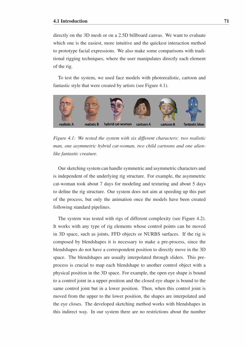
4.1 Introduction 71
directly on the 3D mesh or on a 2.5D billboard canvas. We want to evaluate
which one is the easiest, more intuitive and the quickest interaction method
to prototype facial expressions. We also make some comparisons with tradi-
tional rigging techniques, where the user manipulates directly each element
of the rig.
To test the system, we used face models with photorealistic, cartoon and
fantastic style that were created by artists (see Figure 4.1).
Figure 4.1: We tested the system with six different characters: two realistic
man, one asymmetric hybrid cat-woman, two child cartoons and one alien-
like fantastic creature.
Our sketching system can handle symmetric and asymmetric characters and
is independent of the underlying rig structure. For example, the asymmetric
cat-woman took about 7 days for modeling and texturing and about 5 days
to define the rig structure. Our system does not aim at speeding up this part
of the process, but only the animation once the models have been created
following standard pipelines.
The system was tested with rigs of different complexity (see Figure 4.2).
It works with any type of rig elements whose control points can be moved
in 3D space, such as joints, FFD objects or NURBS surfaces. If the rig is
composed by blendshapes it is necessary to make a pre-process, since the
blendshapes do not have a correspondent position to directly move in the 3D
space. The blendshapes are usually interpolated through sliders. This pre-
process is crucial to map each blendshape to another control object with a
physical position in the 3D space. For example, the open eye shape is bound
to a control joint in a upper position and the closed eye shape is bound to the
same control joint but in a lower position. Then, when this control joint is
moved from the upper to the lower position, the shapes are interpolated and
the eye closes. The developed sketching method works with blendshapes in
this indirect way. In our system there are no restrictions about the number

4.1 Introduction 72
of joints neither on their placement on the mesh. We tested rigs that have
between 25 to 39 joints and rigs with about 56 shapes, which are controlled
by 14 new control joints.
Figure 4.2: Rigs with different complexity; left: a simple rig based only on
a highly articulated facial skeleton, composed by 33 joints; right: a complex
rig based on joints, shapes and lattices to provide additional deformation in
the brows and mouth regions.
We have carried out two different experiments. In the first experiment,
which we call Facial Posing Experiment, we tested the usability and the per-
formance of the sketching method, by measuring the user’s effort (number of
clicks, curves created, modified and deleted) and by computing the time the
user took to create a pose. In the second experiment, which we call Facial
Retargeting Experiment, we tested the accuracy of our retargeting method.
The idea is to evaluate if a source model expression can be accurately repro-
duced on different target characters. We also performed a test to measure
the response time of the system, which we call Performance Test. Finally we
present LIFEisGAME, a Case Study for Therapeutic Purposes, which benefits
from the core method developed in this research.

4.2 Facial Posing Experiment 73
4.2 Facial Posing Experiment
This experiment was designed in order to evaluate the effectiveness of our
facial system. It reveals if our sketching interaction models are valid to create
facial expressions. It also evaluates how comfortable artists feel in incorporat-
ing these models in their production pipeline. We compared our control sys-
tem to traditional rigging techniques, where the user manipulates directly the
individual controls of the rig. We consider our sketching interaction models
more natural and intuitive to users than the traditional technique. Therefore,
we have formulated the following four hypotheses for this experiment:
• H1: Our sketching interaction models are easier and more intuitive to
create facial expressions than the traditional technique;
• H2: The 2D sketching interface reduces the user’s time to create facial
expressions when compared to the traditional technique;
• H3: The 3D sketching interface reduces the user’s time to create facial
expressions when compared to the traditional technique;
• H4: It is easier and more intuitive to deform the model by drawing
strokes on a 2D canvas than drawing strokes directly on the 3D mesh;
The user’s effort (H1) was evaluated through the answers collected in a
questionnaire related to the usability of the three interaction models: 2D
sketch-approach, 3D sketch-approach and traditional-approach. The time to
create facial expressions (H2,H3) was validated by objective quantitative mea-
surements, since we recorded the average time users took to create a pose. The
user’s effort (H4) between drawing strokes on the mesh or on the canvas was
evaluated not only through an usability questionnaire, but also by analyzing
the user activities: number of clicks, number of curves created, modified and
deleted.
The independent variables involved in this experiment were:
• The interaction model (2D sketch-based, 3D sketch-based or traditional).
• The facial expression to be created (see the three poses in Figure 4.3).
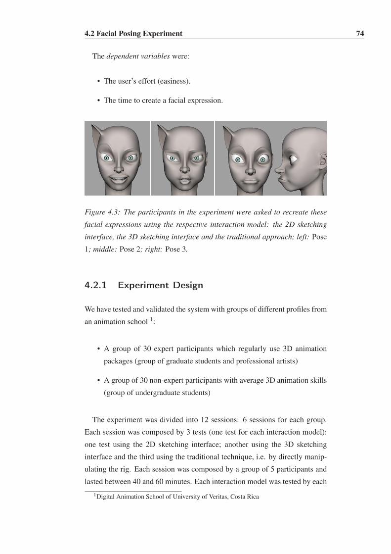
4.2 Facial Posing Experiment 74
The dependent variables were:
• The user’s effort (easiness).
• The time to create a facial expression.
Figure 4.3: The participants in the experiment were asked to recreate these
facial expressions using the respective interaction model: the 2D sketching
interface, the 3D sketching interface and the traditional approach; left: Pose
1; middle: Pose 2; right: Pose 3.
4.2.1 Experiment Design
We have tested and validated the system with groups of different profiles from
an animation school 1:
• A group of 30 expert participants which regularly use 3D animation
packages (group of graduate students and professional artists)
• A group of 30 non-expert participants with average 3D animation skills
(group of undergraduate students)
The experiment was divided into 12 sessions: 6 sessions for each group.
Each session was composed by 3 tests (one test for each interaction model):
one test using the 2D sketching interface; another using the 3D sketching
interface and the third using the traditional technique, i.e. by directly manip-
ulating the rig. Each session was composed by a group of 5 participants and
lasted between 40 and 60 minutes. Each interaction model was tested by each
1Digital Animation School of University of Veritas, Costa Rica
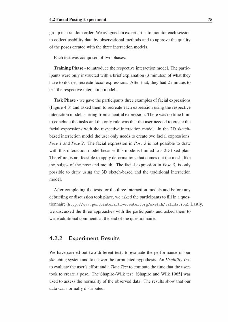
4.2 Facial Posing Experiment 75
group in a random order. We assigned an expert artist to monitor each session
to collect usability data by observational methods and to approve the quality
of the poses created with the three interaction models.
Each test was composed of two phases:
Training Phase - to introduce the respective interaction model. The partic-
ipants were only instructed with a brief explanation (3 minutes) of what they
have to do, i.e. recreate facial expressions. After that, they had 2 minutes to
test the respective interaction model.
Task Phase - we gave the participants three examples of facial expressions
(Figure 4.3) and asked them to recreate each expression using the respective
interaction model, starting from a neutral expression. There was no time limit
to conclude the tasks and the only rule was that the user needed to create the
facial expressions with the respective interaction model. In the 2D sketch-
based interaction model the user only needs to create two facial expressions:
Pose 1 and Pose 2. The facial expression in Pose 3 is not possible to draw
with this interaction model because this mode is limited to a 2D fixed plan.
Therefore, is not feasible to apply deformations that comes out the mesh, like
the bulges of the nose and mouth. The facial expression in Pose 3, is only
possible to draw using the 3D sketch-based and the traditional interaction
model.
After completing the tests for the three interaction models and before any
debriefing or discussion took place, we asked the participants to fill in a ques-
tionnaire (http://www.portointeractivecenter.org/sketch/validation). Lastly,
we discussed the three approaches with the participants and asked them to
write additional comments at the end of the questionnaire.
4.2.2 Experiment Results
We have carried out two different tests to evaluate the performance of our
sketching system and to answer the formulated hypothesis. An Usability Test
to evaluate the user’s effort and a Time Test to compute the time that the users
took to create a pose. The Shapiro-Wilk test [Shapiro and Wilk 1965] was
used to assess the normality of the observed data. The results show that our
data was normally distributed.

4.2 Facial Posing Experiment 76
Usability Test
In order to answer the hypothesis H1 we have analyzed the question Q2 of the
usability questionnaire:
• Which method (sketch-based or traditional) is easier and more intuitive
to use?
We observed that the answers vary with the participant’s profile, so the
results were very different for experts and non-experts participants (see Figure
4.4).
Figure 4.4: Only the expert participants found the sketching method easier
and more intuitive to use.
With a 95% confidence interval for the mean (M = 0.66,SD= 0.48,CL.95 =
0.50 to 0.80), we can affirm that the expert participants agree that the sketch-
ing method is easier and more intuitive to use than the traditional technique.
On the contrary and with the same confidence interval for the mean (M =
0.33,SD = 0.47,CL.95 = 0.18 to 0.48), we can state that the non-expert par-
ticipants disagree that the sketching method is easier and more intuitive to use
than the traditional technique.
During the 3D sketching tests, we observed that the non-experts could not
easily predict the relationship between the drawn stroke and the final result.
For this reason, they answered that they prefer the traditional method where
they can, step-by-step, achieve their desired result. On the other hand, we
observed that experts knew in advance how the stroke should be drawn and
what would be the final deformation.
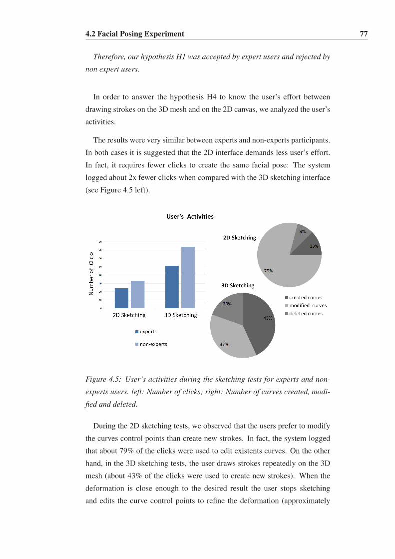
4.2 Facial Posing Experiment 77
Therefore, our hypothesis H1 was accepted by expert users and rejected by
non expert users.
In order to answer the hypothesis H4 to know the user’s effort between
drawing strokes on the 3D mesh and on the 2D canvas, we analyzed the user’s
activities.
The results were very similar between experts and non-experts participants.
In both cases it is suggested that the 2D interface demands less user’s effort.
In fact, it requires fewer clicks to create the same facial pose: The system
logged about 2x fewer clicks when compared with the 3D sketching interface
(see Figure 4.5 left).
Figure 4.5: User’s activities during the sketching tests for experts and non-
experts users. left: Number of clicks; right: Number of curves created, modi-
fied and deleted.
During the 2D sketching tests, we observed that the users prefer to modify
the curves control points than create new strokes. In fact, the system logged
that about 79% of the clicks were used to edit existents curves. On the other
hand, in the 3D sketching tests, the user draws strokes repeatedly on the 3D
mesh (about 43% of the clicks were used to create new strokes). When the
deformation is close enough to the desired result the user stops sketching
and edits the curve control points to refine the deformation (approximately

4.2 Facial Posing Experiment 78
37% of the clicks were used to change existent curves). In the 3D sketching
tests, much more curves were deleted when compared with the 2D sketching
interface. In fact, during the 3D tests, about 20% of the clicks were used to
delete curves.
Also the questionnaire results confirmed our observations. Actually, after
analyzing the results of question Q9:
• Which do you think is more intuitive: sketching on the canvas or on the
mesh?
The results were very similar for experts and non-experts participants (see
Figure 4.6).
Figure 4.6: All the participants, experts and non-experts, found sketching on
the canvas more intuitive than on the 3D mesh.
We can state with a 95% confidence interval for the mean ( M = 0.67,SD =
0.47,CL.95 = 0.52 to 0.82), that the participants agree that it is easier and
more intuitive to draw strokes on the canvas than doing it directly on the 3D
mesh.
Therefore, we accept the hypothesis H4 by both expert and non-expert
users.
The results of this usability test revealed quite curious, when compared to
a previous pilot study [Miranda et al. 2012] between the 2D and 3D sketching
interfaces. Our pilot study showed that the 3D interface was faster and de-
mands less user’s effort than the 2D one, but recent testing proves the contrary.
While on our previous pilot study the participant had a guide that explained

4.2 Facial Posing Experiment 79
the regions of the face, in this study the participants did not have any help.
So, we observed in the 3D sketching interface that the users could not easily
identify the region to be deformed and, consequently, many clicks were done
and curves were modified and deleted. Therefore, we concluded that the inter-
action mode between the action of the user and the deformation of the model
must include a visual feedback with the facial regions to assist the user. A
solution could be to simply highlight the region to be deformed, allowing the
user to correctly identify the desired area. This will be subject for a future
reimplementation of the plugin.
Time Test
In order to answer the hypothesis H2 and H3, we analyzed the average time
to create a pose for each interaction model (see Figure 4.7).
Figure 4.7: We recorded the time it takes the participants to create each ex-
pression with each interaction mode. This graph shows the timing results for
experts and non-experts users.
To evaluate if the interaction model has a significant effect on the time to
create a pose, we accomplished statistical tests. We performed a one-way
repeated measure ANOVA 2 on the time to create a pose with the three inter-
2Based on [Field and Hole 2003], analysis of variance (ANOVA) is a parametric test used
when there are three or more levels of the independent variable. When the same participants
take part in all experimental conditions, a one-way repeated measure ANOVA is employed.

4.2 Facial Posing Experiment 80
action methods. Post-hoc analysis was performed using Fisher’s LSD com-
parisons of means [Fisher 1925], which is a conservative test for significance.
The results vary accordingly to the participant profile, as explained in the
following.
Expert Users. The results of this study revealed that the 2D sketching in-
terface was practically as fast as the traditional technique. The participants
took an average of 1.96 minutes to create a pose with the 2D sketching inter-
face and an average of 1.82 minutes with the traditional technique. With the
3D sketching interface they took an average of 2.88 minutes. We see this as
a very positive result because these kind of participants have years of training
using the individual controls of the rig in Maya.
The data were analyzed using a one-way repeated measure ANOVA. The
results showed that the interaction model had a significant effect on time
F(2,29)= 39.764, p= 0.000. Performing pairwise comparisons using Fisher’s
LSD test revealed that the 2D sketching interface was significantly differ-
ent from 3D interface (p = 0.000) but not significantly different from the
traditional technique (p = 0.285). Therefore, we cannot affirm that the 2D
Sketching interface reduces the user’s time to create facial expressions when
compared to the traditional technique. Consequently the hypothesis H2 can
neither be accepted nor rejected for expert users.
The test also revealed that the 3D sketching interface was significantly dif-
ferent from the traditional technique (p = 0.000). In fact, the user’s time to
create facial expressions using the traditional technique was faster than the
3D sketching model. Therefore, we reject the hypothesis H3 for expert users.
Non-Expert Users. The results of this study reveal that the 2D sketching
interface was faster for creating facial expressions when compared to the other
two approaches. The participants took an average of 2.43 minutes to create
a pose with the 2D sketching interface, an average of 3.94 minutes using the
3D sketching interface and an average of 3.45 minutes with the traditional
technique.
The data were analyzed using a one-way repeated measure ANOVA. The
results showed that the interaction model had a significant effect on time
F(2,29) = 9.693, p= 0.000. Performing pairwise comparisons using Fisher’s

4.2 Facial Posing Experiment 81
LSD test revealed that the 2D sketching interface was significantly differ-
ent from 3D sketching interface (p = 0.000) and from traditional technique
(p = 0.005). Therefore, we can affirm that the 2D Sketching interface is faster
creating facial expressions when compared to the 3D sketching mode and the
traditional approach. Consequently, the hypothesis H2 is accepted for non-
expert users.
The test also revealed that the 3D sketching model was not significantly
different from the traditional approach (p = 0.182). Therefore, the hypothesis
H3 can neither be accepted nor rejected for non-expert users. We cannot
affirm that the 3D Sketching interface reduces the user’s time to create facial
expressions when compared to the traditional technique.
Figure 4.8 shows the difference time to create a pose, between expert and
non-experts participants, for each interaction model. The time results showed
that the expert participants were about 2x faster than the non-expert partic-
ipants to create a pose with the traditional approach. This difference be-
tween experts and non-experts is less significant when they use the sketching
paradigm. In fact, this value fell to about 27% when the 3D sketching is used
and to about 19% when they used the 2D sketching interface. Therefore, the
2D sketching interface seems to require a shorter learning curve.
Figure 4.8: The time difference between experts and non-experts, to create a
pose, is less significant when they use the sketching approach.

4.3 Facial Retargeting Experiment 82
The summary of the user’s qualitative comments about the sketching sys-
tem are:
• Both interaction models in the sketching method are simple and useful
for creating facial deformations;
• Both interaction models in the sketching method produce fast results,
mainly in regions that have many joints;
• The 2D sketching method allows fast and very precise curve editing;
• The 2D sketching interface is better to achieve accurate details, com-
pared to the 3D sketching interaction model;
• The 3D sketching interface is better for a fast approximation to the pose,
compared to the 2D sketching interaction model.
• The 3D sketching interface is better for users with drawing experience
than users with only 3D modeling and animation skills.
4.3 Facial Retargeting Experiment
The perception of a facial expression can potentially be affected by many
elements. The mesh geometry, mesh details (subtleties), the character style
(realistic, cartoon, fantastic) can have an impact on both the final results of the
facial expression and how they are perceived by the spectator. Therefore, we
included in this experiment different character styles, each one with different
details and geometry of different resolutions.
We want to evaluate if our retargeting method preserves, in the target mod-
els, the original emotion manually created on the source character by an artist,
using our sketching system. Therefore, we have formulated the following hy-
potheses for this experiment:
• H1: The facial expression automatically transferred from a source model
to a target model keeps the same emotion;

4.3 Facial Retargeting Experiment 83
The independent variable involved in this experiment was the face of the
3D characters presented in figure 4.1. The dependent variable was the emo-
tion transmitted in the facial expression of the characters.
4.3.1 Experiment Design
Thirty participants, 15 males and 15 females, aged between 25 and 45, com-
pleted the test. All of them were unfamiliar with the experiment and had
no formal knowledge of 3D animation. All of them self-reported normal or
corrected-to-normal vision.
We have designed a test based on matching tasks. We put on a table the
four source models of the Figure 3.22 and gave the participants 20 cards. Each
card has a printing of the target facial models presented in the Figure 3.22. We
asked the participants to match the facial emotion of the target models with
the facial emotion of the source model. There was no time limit to conclude
the task and the only rule was the participant need to associate each card with
the respective source model. Figure 4.9 shows a participant performing the
test.
Figure 4.9: A participant realizing the retargeting experiment.
After completing the test, we asked the participants to answer one simple
question:
1. Which character’s emotion was the most difficult to understand?
4.3.2 Experiment Results
We have carried out a test to evaluate the precision of the retargeting method
and to answer the formulated hypothesis. The observed data in this experi-
4.3 Facial Retargeting Experiment 84
ment follows a normal distribution, accordingly with the Shapiro-Wilk test.
Precision Test
Figure 4.10 shows the average precision of our retargeting method, by char-
acter.
Figure 4.10: The blue character was the one most difficult to perceive his
emotion during the Retargeting experiment.
The results of this study reveals that our retargeting method has, globally,
82% of accuracy. We can state, with a 95% confidence interval for the mean
(M = 0.82,SD = 0.26,CL.95 = 0.74 to 0.90), that the facial expression trans-
ferred from a source model to a target model keeps the same emotion. There-
fore, we accept the hypothesis H1.
In order to identify the character’s emotion most difficult to understand,
we performed a one-way repeated measure ANOVA on the emotion’s percep-
tion for the six characters. The results show that the facial character had a
significant effect on the emotion’s perception F(5,29) = 6.283, p = 0.000.
Performing pairwise comparisons using Fisher’s LSD test revealed that the
fantastic-style character, which we call blue, was significantly different from
all the other characters (p < 0.005). The other characters do not show signif-
icant differences among them (p > 0.005).
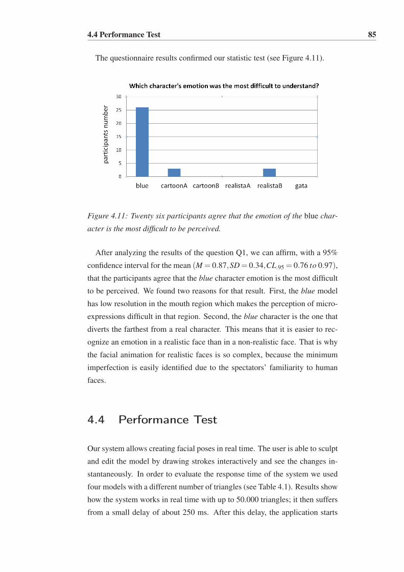
4.4 Performance Test 85
The questionnaire results confirmed our statistic test (see Figure 4.11).
Figure 4.11: Twenty six participants agree that the emotion of the blue char-
acter is the most difficult to be perceived.
After analyzing the results of the question Q1, we can affirm, with a 95%
confidence interval for the mean (M = 0.87,SD= 0.34,CL.95 = 0.76 to 0.97),
that the participants agree that the blue character emotion is the most difficult
to be perceived. We found two reasons for that result. First, the blue model
has low resolution in the mouth region which makes the perception of micro-
expressions difficult in that region. Second, the blue character is the one that
diverts the farthest from a real character. This means that it is easier to rec-
ognize an emotion in a realistic face than in a non-realistic face. That is why
the facial animation for realistic faces is so complex, because the minimum
imperfection is easily identified due to the spectators’ familiarity to human
faces.
4.4 Performance Test
Our system allows creating facial poses in real time. The user is able to sculpt
and edit the model by drawing strokes interactively and see the changes in-
stantaneously. In order to evaluate the response time of the system we used
four models with a different number of triangles (see Table 4.1). Results show
how the system works in real time with up to 50.000 triangles; it then suffers
from a small delay of about 250 ms. After this delay, the application starts

4.5 Case Study for Therapeutic Purposes: LIFEisGAME 86
losing its real time interactive response. We have tested the response time on
characters with and without textures, and we have not experienced any sig-
nificant performance change. Only when about 80.000 triangles is attained,
we can notice some diminishing performance with textured characters. The
tests were made on an Intel Core 2 Duo, with 2GB RAM and an ATI Radeon
X1600 graphics card.
Model Triangles Time Triangles Time Triangles Time
A 29.546 90 41.100 110 82.676 320
B 4.593 80 14.386 80 53.348 250
C 12.284 80 45.536 180 178.544 900
D 16.286 80 24.924 80 59.472 250
Table 4.1: System response times (in milliseconds).
4.5 Case Study for Therapeutic Purposes:
LIFEisGAME
We illustrate the versatility of our sketching method with a learning tool for
therapeutic purposes. LIFEisGAME (LearnIng Facial Emotions usIng Seri-
ous GAMEs, http://www.portointeractivecenter.org/lifeisgame)
attempts to apply a serious game approach to teach children with ASD to rec-
ognize facial emotions using real-time automatic facial expression analysis
and virtual character synthesis. Based on the learning cycle defined in [Kolb
1984], we have outlined in LIFEisGAME four different pedagogical modes.
These range from static to interactive facial emotion recognition.
The sketching method presented on this thesis has been adapted in one of
the game modes that we call "‘Build a Face"’. It runs on regular and touch-
screen computers. The game starts with the player choosing a character from
a list of 3D models and the game mode he wants to play. All modes share the
same user interaction model: the 2D sketching interface. Figure 4.12 shows
the user interface in which the player controls the expressions of the 3D char-
acter by drawing strokes on a canvas on the right-side of the screen. The

4.5 Case Study for Therapeutic Purposes: LIFEisGAME 87
player can drag facial poses to the timeline on the bottom of the screen and,
after setting different expressions, he/she can play the animation. The player
can also take a picture of himself performing a facial expression and then re-
produce the expression by sketching it on the interface. For more information
on the LIFEisGAME project we recommend the reading of [Abirached et al.
2011; Fernandes et al. 2011].
Figure 4.12: LIFEisGAME, sketch-based interface of the game mode Build a
Face. right: the player can draw strokes on the 2D canvas and automatically
deform the cartoon face model; bottom: timeline to drag and drop the facial
poses.
We carried out a pilot study of five children with varied ASD diagnoses.
The testing sessions took place at CRIAR (Autism Association in Portugal)
and every child was accompanied by at least one therapist. In the session,
participants were asked to play with the two versions of the Build a Face game
mode: free-drawing and mimic your picture. The UI configuration is the 2D
sketching interface and the participants only used a touch-screen computer.
The testing result suggests that, in general, the children responded favorably
to the game and enjoyed animating 3D avatars due to the simplicity of the
interaction model. We verified also that some children wanted to draw directly
on the 3D model instead of using the 2D canvas. Therefore, we intend to
prepare a new experiment to study and analyze which user interface (2D or
3D sketching) is the most adequate for children with ASD.
Chapter 5
Conclusions and Future Work
This thesis describes a new approach to manipulate a rig, based on a free-
form sketch-based control method. The sketching method is used to create
a real time control system where facial deformation is sketched on. Based
on its modular design, the facial sketching control system developed in this
research can be easily integrated into existing animation production pipelines
and significantly improve the production workflow. This chapter summarizes
the main conclusions extracted from our research and defines some guidelines
to future work.
5.1 Conclusion
Reproducing the subtleties of a face through animation requires a sophisti-
cated character rig and an associated user interface to provide high-level con-
trols to ease the rig manipulation. As the complexity of the rig grows, creating
all the facial poses of each character is a slow and manual process. We present
a generic facial sketching control system that allows easy, rapid and interac-
tive prototyping of facial poses. Our approach acts directly on the rig of the
model, hiding its complexity from the user, who only needs to draw strokes.
The strokes can be drawn directly on the 3D facial mesh or on a virtual canvas.
The method developed in this thesis is independent of the underlying rig
structure and works with any character style, from realistic to cartoon and

5.1 Conclusion 89
fantastic characters. The 3D models can be defined as a polygonal mesh or
a NURBS surface and there is no limit to the number of vertices. However,
in the tests performed, we observed that with more than 50.000 triangles the
system starts losing its interactive response in real time. The 3D quality of the
models follows the entertainment industry requirements, which was funda-
mental to justify that the results are suitable for high quality CG productions.
In films and videogame productions, artists often build one base model
and then modify it to create new facial poses. Currently, the artists would
need to fine tune the model by directly modifying the geometry or editing
several controls of the rig to reflect the new face. We propose a change of
paradigm in the way a rig can be manipulated. Traditional techniques require
the manipulation of its controls individually, in a discontinuous way, which
can be very time expensive. Our sketching method allows to manipulate a
large number of rig elements at the same time, through a single control curve
drawn on the user interface. As several rig elements are encapsulated in just
one control curve, it is possible to rapidly create complex deformations with
just a single and continuous movement of the hand.
We have developed two different sketching interaction modes: 2D Sketch-
ing Interface and 3D Sketching Interface. In both modes, the user draws free-
form 2D strokes and the system automatically infers depth information, by
constraining the rig elements to the 3D mesh. To allow deformations not con-
strained by the 3D mesh we introduced a 2.5D billboard canvas. It allows
the user to create bulges on the 3D mesh, in any direction. Combining the
direct manipulation on the 3D mesh and the 2.5D billboard canvas permits to
go around the limitations associated to the 2D sketching interface, which is
view-dependent and does not grant non-tangent deformations in the 3D face.
Our sketching method works on the top of a rig structure. This reduces
the ambiguity problem, which occurs in most of the other sketching systems,
since all deformations made by strokes are always constrained by the under-
lying rig. This allows the user to freely and easily draw, without any spe-
cial previous experience and knowledge on the system. However, this does
not mean that all strokes will always produce the correct deformation on the
mesh, but, at least, they will be made accordingly to the defined rig. In con-
trast to the majority of the sketching systems, which are low in precision, the
geometric precision of the deformation made by a stroke, in our approach, is

5.1 Conclusion 90
always constrained by the rig.
During a production, animators often ask for new rig elements to perform
new deformations, like subtle movements of the corner of the lips, which
were not contemplated on the original rig design. In order to support the new
demands, the rig elements as well as the user interface control system must
be updated. With our sketching approach, the user interface always keeps the
same, even with the adjustments of the underlying rig. However, the regions
must be redefined again so that the system becomes ready to use.
The facial sketching system was tested and evaluated on realistic, cartoon
and fantastic characters, to show the versatility of the system. Throughout
our experiments, we have evaluated the usefulness of our sketching system.
We tested its usability by measuring the user’s effort and its performance by
computing the time the user took to create a pose. The timing results of our
sketching interaction models show some variations depending on the exper-
tise level of the participants. Our 2D sketching interface revealed to be as fast
as the traditional approach with expert users, but faster with non-experts. The
3D interface was a little slower than the traditional technique among the ex-
pert users, but does not presents significant time differences with non-experts.
We consider these results positive, since the persons involved in the tests have
years of training in Maya and were completely unfamiliar to our sketching
interaction models. We presented the results to Technical and Art Directors,
who approved the quality of the poses and animations to be used in CG pro-
ductions, replacing the artist generated ones. This is a crucial result: if the
output still requires a lot of tunning, then the sketching system is useless in a
production.
The experiments performed allowed to extract the following conclusions:
• the sketching interaction model is simple to master and useful to create
facial deformations, producing fast results. The participants were able
to create facial poses in a very short amount of time (between 2 and 4
minutes), without any training period, leveraging the intuitive sketching
process, similar to hand-drawing;
• The sketching interaction paradigm requires a shorter learning curve
when compared to traditional rigging techniques;

5.1 Conclusion 91
• The 2D sketching interface is better for users without experience in
moving around the 3D space, when compared to the 3D sketching in-
terface;
Although sketching usually is more natural and intuitive to draw facial ex-
pressions, the rig direct manipulation can be more accurate because it allows
to edit the rig’s controls one by one. So, the artist might prefer it in certain
cases. However, the facial sketching control system developed provides both
interaction modes. It allows to draw free-form strokes to perform a rapid
approximation to the desired deformation and then to edit, individually, the
curve points, to achieve precision. Another advantage when compared to tra-
ditional rigging techniques is that, with our system, the user does not need to
understand how to use the rig parameters. On the contrary, he just needs to
sketch.
Another important feature of the system here proposed is the retargeting of
facial poses between different characters. The retargeting method was tested
to evaluate its accuracy. The results of the tests show that the method has
82% of precision. In practice, it means that our retargeting method preserves
the original emotion created by the artist manually in the source model in
the target models. We consider this result positive because the correspondent
poses were transferred instantly. In order to refine some facial deformation
on the target character, the user can easily edit the transferred strokes. The
system is able to speed up a CG production, because the artist does not need
to create the same facial expression in all the characters. Instead, the artist can
create facial expressions just to one character and then reuse the created poses
in other characters. This improves the workflow as it speeds up the creation of
facial poses, which means increased productivity and reduced costs. However,
the developed retargeting method requires that all the characters, source and
target, have the same rig structure, which turns out to be a limitation.
Although the focus of this thesis is on the dynamics of facial sketching
for artists, the system developed has been further explored in applications
with learning purposes [Abirached et al. 2011; Fernandes et al. 2011], which
benefits from the core method developed in this research.
Please, refer to http://www.portointeractivecenter.org/sketch to
view the videos and additional material related to this research.

5.2 Future Work 92
So, the answer to the hypothesis that inspire this research is:
yes, it is possible to simplify the rig control process, to generate complex
deformations on any 3D face, in real time and through a continuous sketching
interaction.
5.2 Future Work
We conclude this thesis by suggesting some potential directions for future
work. Following this research, an interesting new approach could be the ex-
tension of the method to control other type of objects that are not a face.
Figure 5.1 shows the first results we have achieved in controling a hand and a
rope.
Figure 5.1: Method generalization; left: The hand model has 19 joints, which
are controlled by five 2D fixed and predefined canvas, one for each finger;
right: The rope model has 9 joints, which are controlled just by one 2.5D
dynamic and billboard canvas.
There are many interesting research guidelines that can benefit from the
developed method and extend the implemented facial sketching system.
• Human Computer Interaction: A possible future development is to
combine our sketching interaction model with other traditional rigging
techniques. An interesting case is to use the sketching paradigm to di-
rectly manipulate blendshapes. Lewis and Anjyo approach has already
taken some steps in this direction [Lewis and Anjyo 2010]. Their tech-
nique to directly manipulate blendshapes is simple and efficient but the
interaction model continues to be traditional, based on the individual
selection of control points. Their discontinuous interaction could be
improved by our sketching method, which will allow the manipulation,
in a continuous way, of a large number of blendshapes, at the same
5.2 Future Work 93
time, with a single stroke. Another interesting direction can be to use
the sketching method to directly control the skin. By drawing a stroke
on a certain region of the mesh, the method could increase, on the fly,
the number of polygons in that region (tesselation), in order to empha-
size some facial features, like wrinkles.
• Facial Analysis and Recognition: A facial model can have different
shapes and visual styles, and is divided in several regions. A motivating
research direction is the automatic mapping of these regions: based on
the model’s morphology, the system would suggest the regions defini-
tion and would create the respective drawing areas automatically. While
in an anatomically correct face it is not hard to infer the facial regions (2
brows, 2 eyes, 1 nose, 2 cheeks, 1 mouth), the same is very challenging
to a non-anatomic face.
• Emotion’s Perception: An interesting research guideline is related to
the perception of emotions. It will be interesting to study if it is bet-
ter for the artist, while he is deforming a face, to understand emotions
through sketching interfaces in contrast with traditional interfaces. It
will be better for the artist to perceive the emotion through a continu-
ous or discontinuous interaction?
• Retargeting: The actual version of the system allows the retargeting
of facial poses between characters that have the same rig. It will be in-
teresting to extend the method to support transferring strokes to models
with different rig structures.
The method developed in this research can become part of different types
of applications, like educational learning tools, fast modeling prototyping and
game interface. It can also be integrated in a variety of devices like digital
tables, mobile phones and iPads.
Facial Rigging and Animation, as well as Sketching Interaction, are hot
topics that will continue to provide many research challenges in the next years.
Much work remains to be done and we are excited about the possibilities that
lie ahead. We hope our approach and work motivates other researchers to
come up with new ideas on these areas.

REFERENCES 94
References
ABIRACHED, B., AGGARWAL, J., FERNANDES, T., MIRANDA, J., OR-
VALHO, V., TAMERSOY, B., AND ZHANG, Y. 2011. Improving communi-
cation skills of children with asds through interaction with virtual charac-
ters. In IEEE International Conference on Serious Games and Application
for Health, SeGAH.
ABRANTES, G., AND PEREIRA, F. 1999. Mpeg-4 facial animation technol-
ogy: survey, implementation, and results. Circuits and Systems for Video
Technology, IEEE Transactions on 9, 2 (mar), 290 –305.
AKENINE-MÖLLER, T., HAINES, E., AND HOFFMAN, N. 2008. Real-Time
Rendering 3rd Edition. A. K. Peters, Ltd., Natick, MA, USA.
ALEXANDER, O., ROGERS, M., LAMBETH, W., CHIANG, M., AND DE-
BEVEC, P. 2009. Creating a photoreal digital actor: The digital emily
project. In Proc. SIGGRAPH Course Notes.
ALEXE, A., GAILDRAT, V., AND BARTHE, L. 2004. Interactive modelling
from sketches using spherical implicit functions. In IN PROCEEDINGS
OF AFRIGRAPH, 25–34.
ANDERSON, K., AND MCOWAN, P. 2006. A real-time automated system
for the recognition of human facial expressions. IEEE Transactions on
Systems, Man, and Cybernetics, Part B: Cybernetics 36, 1, 96–105.
ANGELIDIS, A., AND CANI, M.-P. 2004. Swirling-sweepers: Constant-
volume modeling. In In Computer Graphics and Applications, 12th Pacific
Conference on (PGŠ04, 10–15.
ARAI, K., KURIHARA, T., AND ANJYO, K.-I. 1996. Bilinear interpolation
for facial expression and metamorphosis in real-time animation. The Visual
Computer 12, 105–116. 10.1007/BF01725099.
BALCI, K. 2004. Xface: Mpeg-4 based open source toolkit for 3d facial
animation. In AVI ’04: Proceedings of the working conference on Advanced
visual interfaces, ACM Press, New York, NY, USA, 399–402.
BASU, S., OLIVER, N., AND PENTLAND, A. 1998. 3d modeling of human
lip motion. In ICCV’98, 337–343.

REFERENCES 95
BEELER, T., HAHN, F., BRADLEY, D., BICKEL, B., BEARDSLEY, P.,
GOTSMAN, C., SUMNER, R., AND GROSS, M. 2011. High-quality pas-
sive facial performance capture using anchor frames. In Proc. SIGGRAPH
Papers.
BERGERON, P., AND LACHAPELLE, P. 1985. Controlling facial expressions
and body movements in the computer-generated animated short ’tony de
peltrie’. In Proc. SIGGRAPH Papers.
BICKEL, B., BOTSCH, M., ANGST, R., MATUSIK, W., OTADUY, M., PFIS-
TER, H., AND GROSS, M. 2007. Multi-scale capture of facial geometry
and motion. ACM Trans. Graph. 26, 3 (July).
BICKEL, B., LANG, M., BOTSCH, M., OTADUY, M. A., AND GROSS, M.
2008. Pose-space animation and transfer of facial details. In Proceedings
of the 2008 ACM SIGGRAPH/Eurographics Symposium on Computer Ani-
mation, Eurographics Association, Aire-la-Ville, Switzerland, Switzerland,
SCA ’08, 57–66.
BIERMANN, H., MARTIN, I., ZORIN, D., AND BERNARDINI, F. 2001.
Sharp features on multiresolution subdivision surfaces. In Computer
Graphics and Applications, 2001. Proceedings. Ninth Pacific Conference
on, 140 –149.
BLANZ, V., BASSO, C., POGGIO, T., AND VETTER, T. 2003. Reanimating
faces in images and video. In Computer graphics forum, vol. 22, Wiley
Online Library, 641–650.
BORSHUKOV, G., PIPONI, D., LARSEN, O., LEWIS, J. P., AND
TEMPELAAR-LIETZ, C. 2003. Universal capture: image-based facial an-
imation for "the matrix reloaded". In SIGGRAPH ’03: ACM SIGGRAPH
2003 Sketches & Applications, ACM Press, New York, NY, USA, 1–1.
BORSHUKOV, G., MONTGOMERY, J., AND WERNER, W. 2006. Playable
universal capture: compression and real-time sequencing of image-based
facial animation. In SIGGRAPH ’06: ACM SIGGRAPH Courses, ACM
Press, New York, NY, USA, 8.
CHADWICK, J., HAUMANN, D., AND PARENT, R. 1989. Layered con-
struction for deformable animated characters. In ACM Siggraph Computer
Graphics, vol. 23, ACM, 243–252.
REFERENCES 96
CHANG, E., AND JENKINS, O. C. 2006. Sketching articulation and
pose for facial animation. In Proceedings of the 2006 ACM SIG-
GRAPH/Eurographics symposium on Computer animation, Eurographics
Association, Aire-la-Ville, Switzerland, Switzerland, SCA ’06, 271–280.
CHEN, B.-Y., ONO, Y., AND NISHITAD, T. 2005. Character animation
creation using hand-drawn sketches. The Visual Computer 21, 8-10, 551–
558. Pacific Graphics 2005 Conference Proceedings.
CHEN, T., CHENG, M.-M., TAN, P., SHAMIR, A., AND HU, S.-M. 2009.
Sketch2photo: internet image montage. ACM Trans. Graph. 28, 5 (Dec.),
124:1–124:10.
CHERLIN, J. J., SAMAVATI, F., SOUSA, M. C., AND JORGE, J. A. 2005.
Sketch-based modeling with few strokes. In Proceedings of the 21st spring
conference on Computer graphics, ACM, New York, NY, USA, SCCG ’05,
137–145.
CHOE, B., AND KO, H.-S. 2001. Analysis and synthesis of facial expressions
with hand-generated muscle actuation basis. In Computer Animation.
CHOE, B., LEE, H., AND KO, H.-S. 2001. Performance-driven muscle-
based facial animation. The Journal of Visualization and Computer Anima-
tion 12, 2 (May), 67–79.
CHUANG, E., AND BREGLER, C. 2002. Performance driven facial animation
using blendshape interpolation. In Computer Science Technical Report.
CHUANG, E., AND BREGLER, C. 2005. Mood swings: expressive speech
animation. ACM Trans. Graph. 24, 2 (Apr.), 331–347.
CONTERO, M., NAYA, F., JORGE, J., AND CONESA, J. 2003. Cigro: a min-
imal instruction set calligraphic interface for sketch-based modeling. In
Proceedings of the 2003 international conference on Computational sci-
ence and its applications: PartIII, Springer-Verlag, Berlin, Heidelberg,
ICCSA’03, 549–558.
CONTERO, M., NAYA, F., COMPANY, P., SAORIN, J., AND CONESA, J.
2005. Improving visualization skills in engineering education. Computer
Graphics and Applications, IEEE 25, 5 (sept.-oct.), 24 – 31.
REFERENCES 97
COOK, M. T., AND AGAH, A. 2009. A survey of sketch-based 3-d modeling
techniques. Interact. Comput. 21, 3 (July), 201–211.
COQUILLART, S. 1990. Extended free-form deformation: a sculpturing
tool for 3d geometric modeling. In ACM SIGGRAPH Computer Graph-
ics, vol. 24, ACM, 187–196.
CRUZ, L., AND VELHO, L. 2010. A sketch on sketch-based interfaces and
modeling. In Graphics, Patterns and Images Tutorials (SIBGRAPI-T), 2010
23rd SIBGRAPI Conference on, 22 –33.
DAVIS, J., AGRAWALA, M., CHUANG, E., POPOVIC, Z., AND SALESIN, D.
2003. A sketching interface for articulated figure animation. In Proceed-
ings of the 2003 ACM SIGGRAPH/Eurographics symposium on Computer
animation, Eurographics Association, Aire-la-Ville, Switzerland, Switzer-
land, SCA ’03, 320–328.
DENG, Z., AND NOH, J. 2007. Computer facial animation: A survey.
In Data-Driven 3D Facial Animation, Z. Deng and U. Neumann, Eds.
Springer London, 1–28.
DENG, Z., CHIANG, P., FOX, P., AND NEUMANN, U. 2006. Animating
blendshape faces by cross-mapping motion capture data. In Proceedings of
the 2006 symposium on Interactive 3D graphics and games, ACM, 43–48.
DIXON, D., PRASAD, M., AND HAMMOND, T. 2010. icandraw: using
sketch recognition and corrective feedback to assist a user in drawing hu-
man faces. In Proceedings of the 28th international conference on Human
factors in computing systems, ACM, New York, NY, USA, CHI ’10, 897–
906.
DRAPPER, G. M., AND EGBERT, P. 2003. A gestural interface to free-form
deformation. In IN GRAPHICS INTERFACE 2003, 113–120.
DUTREVE, L., MEYER, A., AND BOUAKAZ, S. 2008. Feature points based
facial animation retargeting. In Proceedings of the 2008 ACM symposium
on Virtual reality software and technology, ACM, New York, NY, USA,
VRST ’08, 197–200.

REFERENCES 98
DUTREVE, L., MEYER, A., ORVALHO, V., AND BOUAKAZ, S. 2010. Easy
rigging of face by automatic registration and transfer of skinning parame-
ters. In Proceedings of the 2010 international conference on Computer vi-
sion and graphics: Part I, Springer-Verlag, Berlin, Heidelberg, ICCVG’10,
333–341.
EGGLI, L., YAO HSU, C., BRÜDERLIN, B. D., AND ELBER, G. 1997.
Inferring 3d models from freehand sketches and constraints. Computer-
Aided Design 29, 2, 101 – 112. <ce:title>Solid Modelling</ce:title>.
EITZ, M., HAYS, J., AND ALEXA, M. 2012. How do humans sketch objects?
ACM Trans. Graph. 31, 4 (July), 44:1–44:10.
EITZ, M., RICHTER, R., BOUBEKEUR, T., HILDEBRAND, K., AND
ALEXA, M. 2012. Sketch-based shape retrieval. ACM Trans. Graph.
31, 4 (July), 31:1–31:10.
EKMAN, P., AND FRIESEN, W. 1971. Constants across cultures in the face
and emotion. Journal of Personality and Social Psychology, 17(2), 124–
129.
EKMAN, P., AND FRIESEN, W. 1978. Manual of The Facial Action Coding
System. Consulting Psychologist Press.
EKMAN, P. 1993. Facial expression and emotion. American Psychologist,
48(4), 384U392.
ESCHER, M., PANDZIC, I., AND THALMANN, N. M. 1998. Facial defor-
mations for mpeg-4. In Proceedings of the Computer Animation, IEEE
Computer Society, Washington, DC, USA, CA ’98, 56–.
ESSA, I., BASU, S., DARRELL, T., AND PENTLAND, A. 1996. Model-
ing, tracking and interactive animation of faces and heads using input from
video. In Proceedings of the Computer Animation, IEEE Computer Society,
Washington, DC, USA, CA ’96, 68–.
FALK, R., MINTER, D., VERNON, C., ARETOS, G., MODESTO, L., LAM-
ORLETTE, A., WALKER, N., CHEUNG, T., RENTEL-LAVIN, J., AND
MAX, H. 2004. Art-directed technology: Anatomy of a shrek2 sequence.
In SIGGRAPH Course Notes.

REFERENCES 99
FASEL, B., AND LUETTIN, J. 2003. Automatic facial expression analysis: a
survey. Pattern Recognition 36, 1, 259 – 275.
FERNANDES, T., ALVES, S., MIRANDA, J., QUEIRÓS, C., AND ORVALHO,
V. 2011. A facial character animation system to help recognize facial
emotions. In HCist International Workshop on Health, Springer.
FIELD, A., AND HOLE, G. 2003. How to Design and Report Experiments.
Sage publications Ltd.
FISHER, R. A. 1925. Statistical Methods for Research Workers. Edinburgh:
Oliver and Boyd.
FONSECA, M., FERREIRA, A., AND J.A., J. 2004. Towards 3d modeling
using sketches and retrieval. In Proceedings of eurographics workshop on
sketch-based interfaces and modeling, SBIM ’04.
FORDHAM, J. 2003. Middle earth strikes back. In Cinefex.
FOWLER, B., AND BARTELS, R. 1993. Constraint-based curve manipula-
tion. Computer Graphics and Applications, IEEE 13, 5 (sept.), 43 –49.
FUNKHOUSER, T., MIN, P., KAZHDAN, M., CHEN, J., HALDERMAN, A.,
DOBKIN, D., AND JACOBS, D. 2003. A search engine for 3d models.
ACM Trans. Graph. 22, 1 (Jan.), 83–105.
GAIN, J., AND MARAIS, P. 2005. Warp sculpting. IEEE Transactions on
Visualization and Computer Graphics 11, 2 (Mar.), 217–227.
GARCHERY, S., AND THALMANN, N. 2001. Designing mpeg-4 facial ani-
mation tables for web applications. In Proceedings of Multimedia Model-
ing, 39–59.
GHAHRAMANI, Z., AND HINTON, G. E. 1997. The em algorithm for mix-
tures of factor analyzers. Tech. rep.
GLEICHER, M. 1998. Retargetting motion to new characters. In SIGGRAPH
’98: Proceedings of the 25th annual conference on Computer graphics and
interactive techniques, ACM Press, New York, NY, USA, 33–42.
GORDEN, J. 2005. LightWave 3D (8) Cartoon Character Creation Volume
2: Rigging and Animation. Wordware Publishing.

REFERENCES 100
GRUBB, W. 2009. Facial Animation Rig for Delgo. Tutorial Notes.
GUENTER, B., GRIMM, C., WOOD, D., MALVAR, H., AND PIGHIN, F.
1998. Making faces. In SIGGRAPH: Proc. of the 25th Annual Conference
on Computer Graphics and Interactive Techniques.
GUENTER, B., GRIMM, C., WOOD, D., MALVAR, H., AND PIGHIN, F.
2005. Making faces. In SIGGRAPH ’05: ACM SIGGRAPH 2005 Courses,
ACM Press, New York, NY, USA, 10.
GUNNARSSON, O., AND MADDOCK, S. C. 2010. Sketch-based posing of
3d faces for facial animation. In TPCG - Theory and Practice of Computer
Graphics, Eurographics Association, J. P. Collomosse and I. J. Grimstead,
Eds., 223–230.
HOFFMAN, D. D. 2000. Visual intelligence: how we create what we see.
W.W. Norton & Company.
HOLLY, A. 2006. Facial Rigging for Feature Animation. Fahrenheit Digital,
Training DVD.
HUANG, H., CHAI, J., TONG, X., AND WU, H.-T. 2011. Leveraging motion
capture and 3d scanning for high-fidelity facial performance acquisition.
ACM Trans. Graph. 30, 4 (July), 74:1–74:10.
IGARASHI, T., AND HUGHES, J. F. 2003. Smooth meshes for sketch-based
freeform modeling. In Proceedings of the 2003 symposium on Interactive
3D graphics, ACM, New York, NY, USA, I3D ’03, 139–142.
IGARASHI, T., MATSUOKA, S., AND TANAKA, H. 1999. Teddy: a sketch-
ing interface for 3d freeform design. In Proceedings of the 26th an-
nual conference on Computer graphics and interactive techniques, ACM
Press/Addison-Wesley Publishing Co., New York, NY, USA, SIGGRAPH
’99, 409–416.
IGARASHI, T., MOSCOVICH, T., AND HUGHES, J. F. 2005. Spatial keyfram-
ing for performance-driven animation. In SCA ’05: Proceedings of the
2005 ACM SIGGRAPH/Eurographics symposium on Computer animation,
ACM Press, New York, NY, USA, 107–115.
REFERENCES 101
IRVING, G., SCHROEDER, C., AND FEDKIW, R. 2007. Volume conserving
finite element simulations of deformable models. ACM Trans. Graph. 26,
3 (July).
JI, Z., LIU, L., CHEN, Z., AND WANG, G. 2006. Easy mesh cutting.
Computer Graphics Forum 25, 3, 283–291.
JOLLIFFE, I. T. 1986. Principal Component Analysis. Springer-Verlag.
JORGE, J., SILVA, F., AND CARDOSO, D. 2003. Gides++. In Proc. of the
12th annual Portuguese CG meeting.
JOSHI, P., TIEN, W., DESBRUN, M., AND PIGHIN, F. 2003. Learning
controls for blend shape based realistic facial animation. In SCA ’03: Proc.
of ACM SIGGRAPH/Eurographics Symp. on Computer animation, ACM
Press, Aire-la-Ville, Switzerland, 187–192.
KAHLER, K., HABER, J., AND SEIDEL, H. 2001. Geometry-based muscle
modeling for facial animation. In Graphics Interface, 37–46.
KAHLER, K., HABER, J., YAMAUCHI, H., AND SEIDEL, H. 2002. Head
shop: generating animated head models with anatomical structure.
KARA, L., AND SHIMADA, K. 2006. Construction and modification of 3d
geometry using a sketch-based interface. In Proceedings of EUROGRAPH-
ICS Workshop on Sketch-Based Interfaces and Modeling, SBIM ’06.
KARPENKO, O. A., AND HUGHES, J. F. 2006. Smoothsketch: 3d free-form
shapes from complex sketches. ACM Trans. Graph. 25, 3 (July), 589–598.
KHO, Y., AND GARLAND, M. 2005. Sketching mesh deformations. In ACM
SIGGRAPH 2005 Papers, ACM, New York, NY, USA, SIGGRAPH ’05,
934–934.
KIL, Y. J., RENZULLI, P., KREYLOS, O., HAMANN, B., MONNO, G., AND
STAADT, O. 2005. 3d warp brush: interactive free-form modeling on the
responsive workbench. In Virtual Reality, 2005. Proceedings. VR 2005.
IEEE, 279 –280.
KOENIG, H. A. 1998. Modern computational methods. Taylor & Francis.
REFERENCES 102
KOLB, D. A. 1984. Experiential Learning. Prentice Hall, Englewood Cliffs,
NJ.
KOMOROWSKI, D., MELAPUDI, V., MORTILLARO, D., AND LEE, G. S.
2010. A hybrid approach to facial rigging. In ACM SIGGRAPH ASIA 2010
Sketches, ACM, New York, NY, USA, SA ’10, 42:1–42:2.
KOUADIO, C., POULIN, P., AND LACHAPELLE, P. 1998. Real-time fa-
cial animation based upon a bank of 3d facial expressions. In Computer
Animation 98, IEEE Computer Society, 128–136.
KSHIRSAGAR, S., GARCHERY, S., AND MAGNENAT-THALMANN, N.
2001. Feature point based mesh deformation applied to mpeg-4 facial an-
imation. In Proceedings of the IFIP TC5/WG5.10 DEFORM’2000 Work-
shop and AVATARS’2000 Workshop on Deformable Avatars, Kluwer, B.V.,
Deventer, The Netherlands, The Netherlands, DEFORM ’00/AVATARS
’00, 24–34.
LARBOULETTE, C., CANI, M.-P., AND ARNALDI, B. 2005. Dynamic skin-
ning: Adding real-time dynamic effects to an existing character animation.
In Proc. of the 21st Spring Conference on Computer Graphics.
LASSETER, J. 1987. Principles of traditional animation applied to 3d com-
puter animation. In Proc. of the 14th Annual Conference on Computer
Graphics and Interactive Techniques.
LAU, M., CHAI, J., XU, Y.-Q., AND SHUM, H.-Y. 2007. Face poser: inter-
active modeling of 3d facial expressions using model priors. In Proceedings
of the 2007 ACM SIGGRAPH/Eurographics symposium on Computer ani-
mation, Eurographics Association, Aire-la-Ville, Switzerland, Switzerland,
SCA ’07, 161–170.
LAU, M., CHAI, J., XU, Y.-Q., AND SHUM, H.-Y. 2009. Face poser: In-
teractive modeling of 3d facial expressions using facial priors. ACM Trans.
Graph. 29 (December), 3:1–3:17.
LAVAGETTO, F., AND POCKAJ, R. 1999. The facial animation engine: to-
ward a high-level interface for the design of mpeg-4 compliant animated
faces. Circuits and Systems for Video Technology, IEEE Transactions on 9,
2 (mar), 277 –289.

REFERENCES 103
LAVIOLA, JR., J. J. 2006. Sketching and gestures 101. In ACM SIGGRAPH
2006 Courses, ACM, New York, NY, USA, SIGGRAPH ’06.
LEE, Y., TERZOPOULOS, D., AND WATERS, K. 1995. Realistic modeling
for facial animation. In Proc. SIGGRAPH ’95.
LEE, Y. J., ZITNICK, C. L., AND COHEN, M. F. 2011. Shadowdraw:
real-time user guidance for freehand drawing. In ACM SIGGRAPH 2011
papers, ACM, New York, NY, USA, SIGGRAPH ’11, 27:1–27:10.
LEWIS, J., AND ANJYO, K.-I. 2010. Direct manipulation blendshapes. Com-
puter Graphics and Applications, IEEE 30, 4 (july-aug.), 42 –50.
LEWIS, J. P., CORDNER, M., AND FONG, N. 2000. Pose space deformation:
A unified approach to shape interpolation and skeleton-driven deformation.
In Proc. of the 27th Annual Conference on Computer Graphics and Inter-
active Techniques.
LEWIS, J. P., MOOSER, J., DENG, Z., AND NEUMANN, U. 2005. Reducing
blendshape interference by selected motion attenuation. In Proc. of the
Symposium on Interactive 3D Graphics and Games.
LI, Q., AND DENG, Z. 2008. Orthogonal-blendshape-based editing system
for facial motion capture data. IEEE Comput. Graph. Appl. 28, 6 (Nov.),
76–82.
LIU, X., XIA, S., FAN, Y., AND WANG, Z. 2011. Exploring non-linear
relationship of blendshape facial animation. Computer Graphics Forum
30, 6, 1655–1666.
MACCRACKEN, R., AND JOY, K. I. 1996. Free-form deformations with
lattices of arbitrary topology. In Proceedings of the 23rd annual conference
on Computer graphics and interactive techniques, ACM, New York, NY,
USA, SIGGRAPH ’96, 181–188.
MAGNENAT-THALMANN, N., LAPERRIÈRE, R., AND THALMANN, D.
1988. Joint-dependent local deformations for hand animation and object
grasping. In Proceedings on Graphics interface ’88, Canadian Information
Processing Society, Toronto, Ont., Canada, Canada, 26–33.

REFERENCES 104
MAGNENAT-THALMANN, N., PRIMEAU, E., AND THALMANN, D. 1988.
Abstract muscle action procedures for human face animation. The Visual
Computer 3, 5 (Mar.), 290–297.
MAGUIRE, G. 2008. Facial Animation System for Image Metrics in collabo-
ration with Passion Pictures. Image Metrics.
MAO, C., QIN, S. F., AND WRIGHT, D. 2009. Technical section: A sketch-
based approach to human body modelling. Comput. Graph. 33 (August),
521–541.
MARAFFI, C. 2003. Maya Character Creation: Modeling and Animation
Controls. New Riders Publishing.
MCLAUGHLIN, T., AND SUMIDA, S. 2007. The morphology of digital
creatures. In Proc. of SIGGRAPH ’07 Courses.
MIRANDA, J. C., ALVAREZ, X., ORVALHO, J., GUTIERREZ, D., SOUSA,
A. A., AND ORVALHO, V. 2012. Sketch express: A sketching inter-
face for facial animation. Computers & Graphics 36, 6, 585 – 595.
<ce:title>2011 Joint Symposium on Computational Aesthetics (CAe), Non-
Photorealistic Animation and Rendering (NPAR), and Sketch-Based Inter-
faces and Modeling (SBIM)</ce:title>.
MOHR, A., AND GLEICHER, M. 2003. Building efficient, accurate character
skins from examples. In Proc. SIGGRAPH ’03 Papers.
MORI, M. 1970. The uncanny valley. In Energy, 7(4).
MUCINO, S. 2004. 3dsMax Master Class Series: Advanced Character Rig-
ging. Autodesk, Training DVD.
NATANELI, G., AND FALOUTSOS, P. 2007. Sketching facial expressions. In
ACM SIGGRAPH 2007 sketches, ACM, New York, NY, USA, SIGGRAPH
’07.
NEALE, P. 2008. Intermediate Rigging 4: Facial Rigging Techniques. CG
Academy, Training DVD.
NEALEN, A., SORKINE, O., ALEXA, M., AND COHEN-OR, D. 2005. A
sketch-based interface for detail-preserving mesh editing. In ACM SIG-

REFERENCES 105
GRAPH 2005 Papers, ACM, New York, NY, USA, SIGGRAPH ’05, 1142–
1147.
NEALEN, A., IGARASHI, T., SORKINE, O., AND ALEXA, M. 2007. Fiber-
mesh: designing freeform surfaces with 3d curves. ACM Trans. Graph. 26
(July).
NOH, J., AND NEUMANN, U. 1998. A survey of facial modeling and anima-
tion techniques. Tech. rep., Citeseer.
NOH, J.-Y., AND NEUMANN, U. 2001. Expression cloning. In Proceed-
ings of the 28th annual conference on Computer graphics and interactive
techniques, ACM, New York, NY, USA, SIGGRAPH ’01, 277–288.
NORMAN, D. A. 2002. The design of everyday things, 1. basic paperback
ed., [nachdr.] ed. Basic Books, [New York].
OLSEN, L., SAMAVATI, F., SOUSA, M., AND JORGE, J. 2005. Sketch-based
mesh augmentation. In Proceedings of the 2nd eurographics workshop on
sketch-based interfaces and modeling, SBIM ’05.
OLSEN, L., SAMAVATI, F., SOUSA, M., AND JORGE, J. 2009. Sketch-based
modeling: A survey. Computers & Graphics 33, 85–103.
ORVALHO, V., BASTOS, P., PARKE, F., OLIVEIRA, B., AND ALVAREZ, X.
2012. A facial rigging survey. In in Proc. of the 33rd Annual Conference of
the European Association for Computer Graphics - Eurographics, ACM,
10–32.
ORVALHO, V. 2007. Reusable Facial Rigging and Animation: Create Once,
Use Many. Ph.D. Thesis in Computer Graphics, Universitat Politecnica de
Catalunya.
OSIPA, J. 2007. Stop Staring: Facial Modeling and Animation Done Right.
SYBEX Inc., Alameda, CA, USA.
PANDZIC, I. S., AND FORCHHEIMER, R. 2002. MPEG-4 Facial Animation:
The Standard, Implementation and Applications. John Wiley & Sons.
PANDZIC, I. S. 2002. Facial animation framework for the web and mobile
platforms. In Proceedings of the seventh international conference on 3D
Web technology, ACM, New York, NY, USA, Web3D ’02, 27–34.

REFERENCES 106
PARKE, F. I., AND WATERS, K. 2008. Computer Facial Animation. A.K.
Peters.
PARKE, F. I. 1972. Computer generated animation of faces. In Proc. ACM
National Conference.
PARKE, F. I. 1974. A Parametric Model for Human Faces. Ph.D. Thesis,
University of Utah, Salt Lake City.
PELACHAUD, C., BADLER, N. I., AND VIAUD, N.-L. 1994. Final report
to nsf of the standards for facial animation workshop. In Technical Report,
University of Pennsylvania.
PEREIRA, J., JORGE, J., BRANCO, V., AND FERREIRA, F. 2000. Towards
calligraphic interfaces:sketching 3d scenes with gestures and context icons.
In Proceedings of WSCG Š00.
PEREIRA, J. A. P., JORGE, J. A., BRANCO, V. A., SILVA, N. F., CARDOSO,
T. D., AND FERREIRA, F. N. 2004. Cascading recognizers for ambiguous
calligraphic interaction. In Proceedings of the First Eurographics confer-
ence on Sketch-Based Interfaces and Modeling, Eurographics Association,
Aire-la-Ville, Switzerland, Switzerland, SBM’04, 63–72.
PIEGL, L. 1987. Interactive data interpolation by rational bezier curves.
Computer Graphics and Applications, IEEE 7, 4 (april), 45 –58.
PIGHIN, F., AND LEWIS, J. P. 2006. Facial motion retargeting. In Proc.
SIGGRAPH ’06 Courses.
PIGHIN, F., HECKER, J., LISCHINSKI, D., SZELISKI, R., AND SALESIN,
D. 1998. Synthesizing realistic facial expressions from photographs. In
Proc. SIGGRAPH ’98.
PIXAR, 1986. Luxo jr.
PLATT, S. M., AND BADLER, N. I. 1981. Animating facial expressions.
In SIGGRAPH ’81: Proc. of Conf. on Computer graphics and interactive
techniques, ACM Press, New York, NY, USA, 245–252.
PORTER, T. 1997. Creating lifelike characters in toy story. In Newsletter of
ACM SIGART Bulletin.

REFERENCES 107
PRESS, W. H., TEUKOLSKY, S. A., VETTERLING, W. T., AND FLANNERY,
B. P., 1992. Numerical recipes in c: The art of scientific computing. second
edition.
REVERET, L., AND ESSA, I. 2001. Visual coding and tracking of speech
related facial motion.
RITCHIE, K.; ALEXANDER, O. . B. K. 2006. The Art of Rigging: A Defini-
tive Guide to Character Technical Direction with Alias Maya. CG Toolkit.
ROGERS, D. F. 1989. Constrained b-spline curve and surface fitting. Comput.
Aided Des. 21, 10 (Dec.), 641–648.
SAMET, H. 2005. Foundations of Multidimensional and Metric Data Struc-
tures (The Morgan Kaufmann Series in Computer Graphics and Geometric
Modeling). Morgan Kaufmann Publishers Inc., San Francisco, CA, USA.
SCHLEIFER, J., SCADUTO-MENDOLA, R., CANETTI, Y., AND PIRETTI,
M. 2002. Character setup from rig mechanics to skin deformations: A
practical approach. In Proc. SIGGRAPH ’02 Course Notes.
SCHMIDT, R., WYVILL, B., SOUSA, M. C., AND JORGE, J. A. 2005.
Shapeshop: Sketch-based solid modeling with blobtrees. In Proceedings of
Eurographics Symposium on Sketch-Based Interfaces and Modeling, SBIM
’05.
SCHREER, O., ENGLERT, R., EISERT, P., AND TANGER, R. 2008. Real-
time vision and speech driven avatars for multimedia applications. Trans.
Multi. 10, 3 (Apr.), 352–360.
SEDERBERG, T. W., AND PARRY, S. R. 1986. Free-form deformation of
solid geometric models. In Proc. Computer Graphics and Interactive Tech-
niques.
SEN TANG, S., LIEW, A. W.-C., AND YAN, H. 2004. Lip-sync in human
face animation based on video analysis and spline models. Multi-Media
Modeling Conference, International 0, 102.
SEO, J., IRVING, G., LEWIS, J. P., AND NOH, J. 2011. Compression and
direct manipulation of complex blendshape models. ACM Trans. Graph.
30, 6 (Dec.), 164:1–164:10.

REFERENCES 108
SEVERN, A., SAMAVATI, F., AND SOUSA, M. C. 2006. Transformation
strokes. In Proceedings of the 3rd Eurographics Workshop on Sketch-Based
Interfaces and Modeling, 75–82.
SEZGIN, T. M., AND DAVIS, A. 2004. Scale-space based feature point
detection for digital ink. In In AAAI 2004 Fall Symposium Series, Sketch
Understanding.
SEZGIN, T. M., STAHOVICH, T., AND DAVIS, R. 2006. Sketch based in-
terfaces: early processing for sketch understanding. In ACM SIGGRAPH
2006 Courses, ACM, New York, NY, USA, SIGGRAPH ’06.
SEZGIN, T. M. 2001. Sketch based interfaces: Early processing for sketch
understanding. In Proceedings of PUI-2001. NY, ACM Press.
SHAPIRO, S. S., AND WILK, M. B. 1965. An analysis of variance test for
normality (complete samples). Biometrika 52, 3-4, 591–611.
SHIN, H., AND IGARASHI, T. 2007. Magic canvas: interactive design of a
3-d scene prototype from freehand sketches. In Proceedings of Graphics
Interface 2007, ACM, New York, NY, USA, GI ’07, 63–70.
SHINAR, T., SCHROEDER, C., AND FEDKIW, R. 2008. Two-way coupling
of rigid and deformable bodies. In Proceedings of the 2008 ACM SIG-
GRAPH/Eurographics Symposium on Computer Animation, Eurographics
Association, Aire-la-Ville, Switzerland, Switzerland, SCA ’08, 95–103.
SIFAKIS, E., NEVEROV, I., AND FEDKIW, R. 2005. Automatic determina-
tion of facial muscle activations from sparse motion capture marker data.
In Proc. SIGGRAPH Papers.
SIFAKIS, E., SELLE, A., ROBINSON-MOSHER, A., AND FEDKIW, R. 2006.
Simulating speech with a physics-based facial muscle model. In Proceed-
ings of the 2006 ACM SIGGRAPH/Eurographics symposium on Computer
animation, Eurographics Association, Aire-la-Ville, Switzerland, Switzer-
land, SCA ’06, 261–270.
SINGH, K., OHYA, J., AND PARENT, R. 1995. Human figure synthesis
and animation for virtual space teleconferencing. Virtual Reality Annual
International Symp. ’95. IEEE, 118–126.

REFERENCES 109
SIVIC, J., AND ZISSERMAN, A. 2003. Video google: A text retrieval ap-
proach to object matching in videos. In Proceedings of the Ninth IEEE
International Conference on Computer Vision - Volume 2, IEEE Computer
Society, Washington, DC, USA, ICCV ’03, 1470–.
SKONICKI, M. 2008. Facial Rigging for Games. Eat 3D, Training DVD.
SQUIRE, D. M., MÜLLER, W., MÜLLER, H., AND PUN, T. 2000. Content-
based query of image databases: inspirations from text retrieval. Pattern
Recognition Letters 21, 13U14, 1193 – 1198. <ce:title>Selected Papers
from The 11th Scandinavian Conference on Image</ce:title>.
SUCONTPHUNT, T., MO, Z., NEUMANN, U., AND DENG, Z. 2008. In-
teractive 3d facial expression posing through 2d portrait manipulation. In
Proceedings of graphics interface 2008, Canadian Information Processing
Society, Toronto, Ont., Canada, Canada, GI ’08, 177–184.
SUMNER, R. W., AND POPOVIC, J. 2004. Deformation transfer for triangle
meshes. In ACM SIGGRAPH 2004 Papers, ACM, New York, NY, USA,
SIGGRAPH ’04, 399–405.
SUTHERLAND, I. E. 1964. Sketch pad a man-machine graphical communi-
cation system. In Proceedings of the SHARE design automation workshop,
ACM, New York, NY, USA, DAC ’64, 6.329–6.346.
TAI, C.-L., ZHANG, H., AND FONG, J. C.-K. 2004. Prototype model-
ing from sketched silhouettes based on convolution surfaces. Computer
Graphics Forum 23, 1, 71–83.
TERAN, J., SIFAKIS, E., BLEMKER, S. S., NG-THOW-HING, V., LAU, C.,
AND FEDKIW, R. 2005. Creating and simulating skeletal muscle from the
visible human data set. IEEE Transactions on Visualization and Computer
Graphics 11, 3 (May), 317–328.
TERZOPOULOS, D., AND WATERS, K. 1990. Physically-based facial mod-
elling, analysis, and animation. The Journal of Visualization and Computer
Animation 1, 2, 73–80.
THORNE, M., BURKE, D., AND VAN DE PANNE, M. 2004. Motion doodles:
an interface for sketching character motion. In ACM SIGGRAPH 2004
Papers, ACM, New York, NY, USA, SIGGRAPH ’04, 424–431.

REFERENCES 110
TIPPING, M. E., AND BISHOP, C. M., 1998. Mixtures of probabilistic prin-
cipal component analysers.
TURNER, R., AND THALMANN, D. 1993. The elastic surface layer model for
animated character construction. Proc. of Computer Graphics International
’93, 399–412.
VILLAGRASA, S., AND SUSIN, A. 2009. Face! 3d facial animation system
based on facs. In IV Ibero-American Symposium in Computer Graphics.
VLASIC, D., BRAND, M., PFISTER, H., AND POPOVIC, J. 2005. Face
transfer with multilinear models. ACM Trans. Graph. 24, 3 (July), 426–
433.
WANG, H., AND MARKOSIAN, L. 2007. Free-form sketch. In Proceedings of
the 4th Eurographics workshop on Sketch-based interfaces and modeling,
ACM, New York, NY, USA, SBIM ’07, 53–58.
WANG, X. C., AND PHILLIPS, C. 2002. Human skin model capable of nat-
ural shape variation. In Proc. of the 2002 ACM SIGGRAPH/Eurographics
Symposium on Computer Animation.
WARD, A. 2004. Game Character Development with Maya. New Riders
Publishing.
WATERS, K., AND LEVERGOOD, T. M. 1993. Decface: An automatic lip-
synchronization algorithm for synthetic faces. Tech. rep., Multimedia Tools
and Applications.
WATERS, K. 1987. A muscle model for animating three-dimensional facial
expression. In Proc. SIGGRAPH ’87.
WEISE, T., BOUAZIZ, S., LI, H., AND PAULY, M. 2011. Realtime
performance-based facial animation. In ACM SIGGRAPH 2011 papers,
ACM, New York, NY, USA, SIGGRAPH ’11, 77:1–77:10.
WILLIAMS, L. 1990. Electronic mask technology. In Proc. SIGGRAPH ’90
Course Notes, State of the Art in Facial Animation.
WU, Y., KALRA, P., AND THALMANN, N. 1996. Simulation of static and
dynamic wrinkles of skin. Proc. of Computer Animation ’96, 90–97.
REFERENCES 111
WYVILL, B., FOSTER, K., JEPP, P., SCHMIDT, R., SOUSA, M., AND
JORGE, J. 2005. Sketch based construction and rendering of implicit mod-
els. In Proceedings of euro-graphics workshop on computational aesthetics
in graphics, visualization and imaging.
YANG, X., AND ZHANG, J. 2006. Stretch it - realistic smooth skinning. In
Proc. of the International Conference on Computer Graphics, Imaging and
Visualisation, IEEE Computer Society.
YANG, C., SHARON, D., AND VAN DE PANNE, M. 2005. Sketch-based
modeling of parameterized objects. In ACM SIGGRAPH 2005 Sketches,
ACM, New York, NY, USA, SIGGRAPH ’05.
YUAN, X., XU, H., NGUYEN, M., SHESH, A., AND CHEN, B. 2005.
Sketch-based segmentation of scanned outdoor environment models. In
Proceedings of eurographics workshop on sketch-based interfaces and
modeling, SBIM ’05.
ZELEZNIK, R. C., HERNDON, K. P., AND HUGHES, J. F. 1996. Sketch: an
interface for sketching 3d scenes. In ACM SIGGRAPH 1996, ACM, New
York, NY, USA, SIGGRAPH ’96.
ZHANG, Q., LIU, Z., GUO, B., AND SHUM, H. 2003. Geometry-driven
photorealistic facial expression synthesis. In Proceedings of the 2003 ACM
SIGGRAPH/Eurographics symposium on Computer animation, Eurograph-
ics Association, Aire-la-Ville, Switzerland, Switzerland, SCA ’03, 177–
186.
ZHANG, L., SNAVELY, N., CURLESS, B., AND SEITZ, S. M. 2004. Space-
time faces: high resolution capture for modeling and animation. In SIG-
GRAPH ’04: ACM SIGGRAPH 2004 Papers, ACM Press, New York, NY,
USA, 548–558.
ZHAO, W., CHELLAPPA, R., PHILLIPS, P. J., AND ROSENFELD, A. 2003.
Face recognition: A literature survey. ACM Comput. Surv. 35, 4 (Dec.),
399–458.
ZIMMERMANN, J., NEALEN, A., AND ALEXA, M. 2007. Silsketch: auto-
mated sketch-based editing of surface meshes. In Proceedings of the 4th
Eurographics workshop on Sketch-based interfaces and modeling, ACM,
New York, NY, USA, SBIM ’07, 23–30.

Appendix A
Publications and Awards
A.1 Publications and Conferences
These are the most significant publications and respective abstracts that re-
sulted from the PhD research.
[2012]
MIRANDA, J. C., ALVAREZ, X., ORVALHO, J.,
GUTIERREZ, D., SOUSA, A. A., AND ORVALHO,
V. 2012. Sketch express: A sketching interface for
facial animation. In Journal Computer and Graph-
ics, Issue 6, Volume 36, Pp. 585-595. Prémio
Professor José Luis Encarnação 2012 - Honorable
Mention.
One of the most challenging tasks for an animator is to quickly create convinc-
ing facial expressions. Finding an effective control interface to manipulate fa-
cial geometry has traditionally required experienced users (usually technical
directors), who create and place the necessary animation controls. Here we
present our sketching interface control system , designed to reduce the time
and effort necessary to create facial animations. Inspired in the way artists
draw, where simple strokes define the shape of an object, our approach al-
lows the user to sketch such strokes either directly on the 3D mesh or on two
different types of canvas: a 2D fixed canvas or more flexible 2.5D dynamic

A.1 Publications and Conferences 113
screen-aligned billboards. In all cases, the strokes do not control the geometry
of the face, but the underlying animation rig instead, allowing direct manip-
ulation of the rig elements. Additionally, we show how the strokes can be
easily reused in different characters, allowing retargeting of poses on several
models. We illustrate our interactive approach using varied facial models of
different styles showing that first time users typically create appealing 3D
poses and animations in just a few minutes. We also present in this article the
results of a user study. We deploy our method in an application for an artistic
purpose. Our system has also been used in a pioneer serious game context,
where the goal was to teach people with Autism Spectrum Disorders (ASD)
to recognize facial emotions, using real time synthesis and automatic facial
expression analysis.
MIRANDA, J. C., ALVAREZ, X., SOLENO, J.,
SOUSA, A. A., FERNÁNDEZ, I., AND ORVALHO,
V. 2012. Perceiving Interactive Sketching Through
Facial Expressions. In Proceedings of the ACM
Symposium on Applied Perception (SAP ’12) .
ACM, New York, NY, USA, Pp. 127. Best
Poster/Demo :: Selected for SIGGRAPH’12 Poster
Session.
The videogame and film industry drive the demand for powerful intuitive in-
terfaces that allow artists to quickly produce believable facial expressions. For
an effective interface to create facial deformation, we have developed a facial
sketching interface control system, based on simple strokes drawn directly on
a 3D face or on a 2D virtual canvas. We present a user study to understand
which interaction models ease the creation of facial expressions. We tested
and validated the system in order to compare our different sketching interac-
tion models and the traditional rigging technique. The results show that users
are able to create facial poses in a very short amount of time with our sketch-
ing interaction models, even without any previous training. This allows to
control a 3D model in an intuitive sketching process, just like simply paint-
ing with a brush on a canvas. The sketching interaction paradigm requires a
shorter learning curve when compared to the traditional technique. The 2D
mode reveals more user-friendly for people that have low expertise and the
3D for those with drawing experience.

A.1 Publications and Conferences 114
[2011]
MIRANDA, J. C., ALVAREZ, X., ORVALHO, J.,
GUTIERREZ, D., SOUSA, A. A., AND ORVALHO,
V. 2011. Sketch express: facial expressions made
easy. In Proceedings of the Eighth Eurographics
Symposium on Sketch-Based Interfaces and Model-
ing (SBIM ’11). ACM, New York, NY, USA, 87-94.
Best Paper Award.
Finding an effective control interface to manipulate complex geometric ob-
jects has traditionally relied on experienced users to place the animation con-
trols. This process, whether for key framed or for motion captured animation,
takes a lot of time and effort. We introduce a novel sketching interface control
system inspired in the way artists draw, in which a stroke defines the shape
of an object and reflects the user’s intention. We also introduce the canvas, a
2D drawing region where the users can make their strokes, which determines
the domain of interaction with the object. We show that the combination of
strokes and canvases provides a new way to manipulate the shape of an im-
plicit volume in space. And most importantly, it is independent from the 3D
model rig. The strokes can be easily stored and reused in other characters,
allowing retargeting of poses. Our interactive approach is illustrated using
facial models of different styles. As a result, we allow rapid manipulation
of 3D faces on the fly in a very intuitive and interactive way. Our informal
study showed that first time users typically master the system within seconds,
creating appealing 3D poses and animations in just a few minutes.
MIRANDA, J. C., FERNANDES, T., SOUSA, A. A.,
AND ORVALHO, V. 2011. Interactive Technology:
Teaching People with Autism to Recognize Facial
Emotions. In Book chapter Autism Spectrum Disor-
ders - From Genes to Environment. Tim Williams
(Ed.), ISBN: 978-953-307-558-7, InTech.
In daily life, we interact with others by exchanging a huge quantity of infor-
mation, including our current states of emotions, through facial expressions.
Thus, faces are crucial for the recognition and understanding of emotions
and for assisting communications and interactions between people. Individ-

A.1 Publications and Conferences 115
uals with Autism Spectrum Disorders (ASD) tend to avoid looking at others
human faces and find it hard to recognize facial expressions and emotions
in themselves and in others (Baron Cohen, 1995). This incapacity to read
emotions on the human face impairs their ability to communicate with other
people (Baron-Cohen et al., 2007). This article gives an overview of existing
methods that have been used for teaching emotion recognition to individuals
with ASD. We identify some technological limitations that difficult their in-
terpersonal interactions. Our contribution is a novel approach to teach autistic
people to recognize emotions from facial expression. Our idea is based on
real-time facial synthesis of 3D characters. We also suggest a different in-
teraction model to involve the autistic patient more deeply in the process of
learning emotions. Creating a solution to solve this problem requires a joint
effort from many research fields, such as computer vision, computer graphics,
human computer interaction and facial behavior and emotions.
FERNANDES, T., ALVES, S., MIRANDA, J.,
QUEIRÓS, C., ORVALHO, V. 2011. A facial Char-
acter Animation System to Help Recognize Facial
Emotions. In HCist International Workshop on
Health. Springer.
This article presents the LIFEisGAME project, a serious game that will help
children with ASD to recognize and express emotions through facial expres-
sions. The game design tackles one of the main experiential learning cycle of
emotion recognition: recognize and mimic (game mode: build a face). We de-
scribe the technology behind the game, which focus on a character animation
pipeline and a sketching algorithm. We detailed the facial expression analyzer
that is used to calculate the score in the game. We also present a study that
analyzes what type of characters children prefer when playing a game. Last,
we present a pilot study we have performed with kids with ASD.
B. ABIRACHED, J. K. AGGARWAL, T. FERNAN-
DES, J. MIRANDA, V. ORVALHO, B. TAMERSOY,
Y. ZHANG 2011. Improving Communication Skills
of Children with ASDs through Interaction with
Virtual Characters. In IEEE International Confer-
ence on Serious Games and Application for Health
(SeGAH’11). Braga, Portugal.

A.1 Publications and Conferences 116
This article presents the LIFEisGAME project, a serious game that will help
children with ASDs to recognize and express emotions through facial expres-
sions. The game design tackles the main experiential learning cycle of emo-
tion recognition: watch and recognize, learn by doing, recognize and mimic,
generalize or knowledge transfer to real life. We briefly describe the tech-
nology behind the character animation pipeline centered on the creation of a
generic rig. Then, we detail the facial expression analyzer that uses Active
Appearance Models. Last, we describe the user study experiment using game
mode "‘recognize the expression"’.
[2010]
MIRANDA, J. C., ALVAREZ, X., SOUSA, A. A.,
GUTIERREZ, D., ORVALHO, J., AND ORVALHO,
V. 2010. Painting on Canvas: A Facial Sketch-
ing Control System. In Eurographics/ACM SIG-
GRAPH Symposium on Computer Animation (SCA
2010) (Poster and Demo). ACM, Madrid, Spain,
Vol. 1, pp. 1 - 2, July, 2010.
Facial Animation in films and videogames has traditionally relied on creating
all the facial poses and animation controls in the early stages of a production.
This process, whether for key framed controls or motion captured animation,
takes a lot of time and effort. We present a novel sketching control system
inspired in the way artists draw, where a stroke defines the shape of an ob-
ject and reflects the userŠs intention. We introduce the canvas, a 2D drawing
region where the users can make their strokes. We present a Sketch-Based
Free-Form Deformation technique that is used to create a real-time simple
control system where facial deformation is sketched on, significantly speed-
ing up the creation of poses. We show that the combination of strokes and
canvases provides a new way to manipulate the shape of an implicit volume
in space. As a result, we allow rapid prototyping of facial expressions on the
fly in a very intuitive and interactive way. Our informal study showed that first
time users typically master the system within seconds, creating appealing 3D
facial poses and animations in just a few minutes.

A.1 Publications and Conferences 117
ORVALHO, V., MIRANDA, J. C., AND SOUSA, A.
A. 2010. What a Feeling: Learning Facial Expres-
sions and Emotions. In Revista Prisma, Edição nž
10 - Especial videojogos 2010. Best paper in Con-
ferência de Ciências e Artes dos Videojogos 2009.
Universidade de Aveiro, Portugal.
People with Autism Spectrum Disorders (ASD) find it difficult to understand
facial expressions. We present a new approach that targets one of the core
symptomatic deficits in ASD: the ability to recognize the feeling states of
others. What a Feeling is a videogame that aims to improve the ability of
socially and emotionally impaired individuals to recognize and respond to
emotions conveyed by the face in a playful way. It enables people from all
ages to interact with 3D avatars and learn facial expressions through a set of
exercises. The game engine is based on real-time facial synthesis. This pa-
per describes the core mechanics of our learning methodology and discusses
future evaluation directions.
[2009]
ORVALHO, V., MIRANDA, J. C., AND SOUSA, A.
A. 2009. Facial Synthesis of 3D Avatars for Thera-
peutic Applications. In Journal of Studies in Health
Technology and Informatics. IOS Press. 144:96-98.
ISSN: 0926-9630.
People with autism spectrum disorder (ASD) find it difficult to recognize and
respond to emotions conveyed by the face. Most existing methodologies to
teach people with ASD to recognize expressions use still images, and do not
take into account that facial expressions have movement. We propose a new
approach that uses state of the art technology to solve the problem and to im-
prove interactivity. It is based on an avatar-user interaction model with real
time response, which builds upon the patient-therapist relationship: it is de-
signed to be used by the therapist and the patient. The core technology behind
it is based on a technique we have developed for real time facial synthesis of
3D characters.

A.2 Invited Talks 118
ORVALHO, V., MIRANDA, J. C., AND SOUSA, A.
A. 2009. What a Feeling: Learning Facial Expres-
sions and Emotions. In Proceedings of Videojogos
2009 - Conferência de Ciências e Artes dos Video-
jogos. Universidade de Aveiro, Portugal.
People with Autism Spectrum Disorders (ASD) find it difficult to understand
facial expressions. We present a new approach that targets one of the core
symptomatic deficits in ASD: the ability to recognize the feeling states of
others. What a Feeling is a videogame that aims to improve the ability of
socially and emotionally impaired individuals to recognize and respond to
emotions conveyed by the face in a playful way. It enables people from all
ages to interact with 3D avatars and learn facial expressions through a set of
exercises. The game engine is based on real-time facial synthesis. This pa-
per describes the core mechanics of our learning methodology and discusses
future evaluation directions.
A.2 Invited Talks
Sketch Express: Facial Expressions Made Easy. Semana da Ciência e Tec-
nologia. Instituto Politécnico da Guarda (IPG). Guarda, Portugal. Novembro
2011.
T-Life - um programa de treino da capacidade de reconhecimento emocional
em pessoas com perturbações do espectro autista. I Congresso Internacional
da Saúde. Simpósio: Realidade Virtual aplicada ao contexto da Saúde e Re-
abilitação. Gaia, Porto, Portugal. Setembro 2010.
Animação Facial 3D no domínio da Reabilitação. Seminário de Engenharia
Informática: Às cegas com ... Engenharia. Instituto Politécnico da Guarda
(IPG). Guarda, Portugal. Abril 2010.
T-Life - um projecto de reconhecimento emocional de faces em pessoas com
autismo. VI Congresso Nacional de Terapia Ocupacional. WorkShop: As
Novas Tecnologias Aplicadas ao Contexto da Saúde e Reabilitação - Algu-
mas Aplicações de Metodologias de Realidade Virtual. Alcochete, Lisboa,
Portugal. Abril 2010.

A.3 Honors and Awards 119
A.3 Honors and Awards
Best Paper Award Winner. Sketch express: facial expressions made easy. In
Eighth Eurographics Symposium on Sketch-Based Interfaces and Modeling
(SBIM ’11). ACM, Vancouver, Canadá, August 2011.
Best Poster/Demo Award Winner. Perceiving Interactive Sketching Through
Facial Expressions. In ACM Symposium on Applied Perception (SAP ’12).
ACM, Los Angels, USA, August 2012.
Honorable Mention (2nd Place). In Prémio Professor José Luis Encarnação
2012, promoted by the Portuguese Computer Graphics Group (GPCG), with
the article Sketch express: A sketching interface for facial animation, pub-
lished in Journal Computer and Graphics, Issue 6, Volume 36. GPCG, Viana
do Castelo, Portugal, Outubro 2012.