Control System Lab Manual Winter14
40
SCHOOL OF ELECTRICAL ENGINEERING (SELECT) B.Tech. (Electrical and Electronics Engineering) ACADEMIC YEAR 2013-14 EEE226 CONTROL SYSTEM LABORATORY MANUAL 2
-
Upload
aditya-jain -
Category
Documents
-
view
64 -
download
8
description
A complete lab manual with procedure and theory for control systems
Transcript of Control System Lab Manual Winter14
SCHOOL OF ELECTRICAL ENGINEERING
(SELECT)
B.Tech. (Electrical and Electronics Engineering)
ACADEMIC YEAR 2013-14
EEE226 CONTROL SYSTEM LABORATORY MANUAL
2
EEE226 CONTROL SYSTEM LABORATORY MANUAL
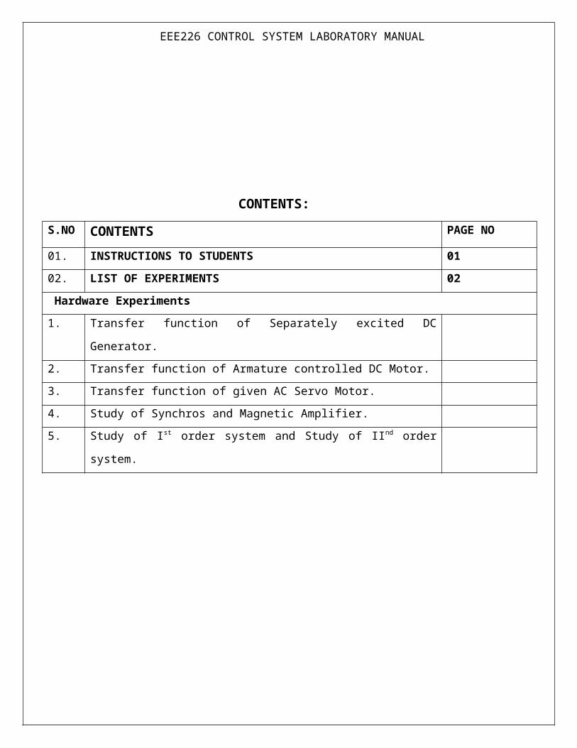
CONTENTS:
S.NO CONTENTS PAGE NO
01. INSTRUCTIONS TO STUDENTS 01
02. LIST OF EXPERIMENTS 02
Hardware Experiments
1. Transfer function of Separately excited DC Generator.
2. Transfer function of Armature controlled DC Motor.
3. Transfer function of given AC Servo Motor.
4. Study of Synchros and Magnetic Amplifier.
5. Study of Ist order system and Study of IInd order system.

EEE226 CONTROL SYSTEM LABORATORY MANUAL
INSTRUCTIONS TO STUDENTS
Control System lab experiments are designed with both software simulation and hardware
experiments.
For each and every lab session, before the class the student would be expected to write down the
Aim, Theory of the experiment, Flow chart associated with the power system study in the
observation.
A basic outline about the necessary algorithm for developing the required program would be
given in the lab class. The students after clarifying the necessary doubts should proceed with the
execution of the program.
For the Hardware experiments, the students should write the Aim, Theory of the experiment and
the procedure for completing the study.
Follow the rules and regulations of the laboratory.
Wear closed shoes while entering the laboratory.
Maintain discipline inside the laboratory.
Prepare the observation / record note book neatly. Draw the required diagrams with the aid of
scale and pencil.
Use procircles for drawing measuring instruments.
Prepare well for answering viva questions.
Don’t switch on the power supply in the absence of Faculty / Staff.
Get the readings verified by the Faculty before disconnecting the circuit components.
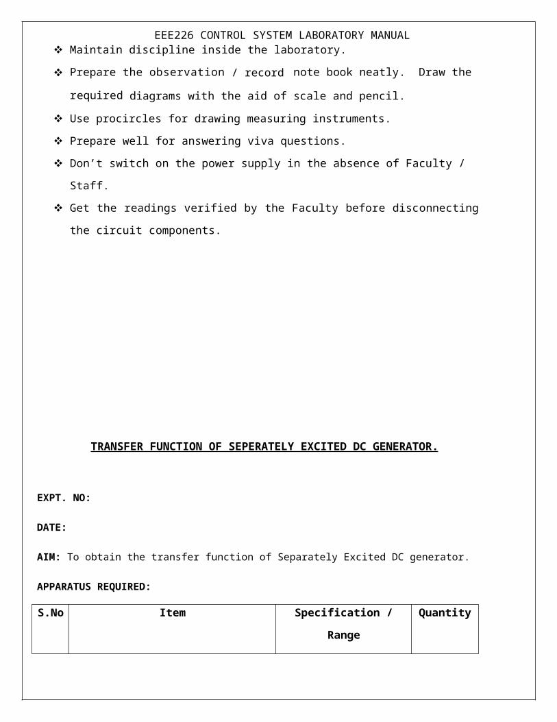
TRANSFER FUNCTION OF SEPERATELY EXCITED DC GENERATOR.
EEE226 CONTROL SYSTEM LABORATORY MANUAL
EXPT. NO:
DATE:
AIM: To obtain the transfer function of Separately Excited DC generator.
APPARATUS REQUIRED:
S.No Item Specification / Range Quantity
1. DC generator trainer kit
2. DC motor – Generator set 0.5HP/180V/1500 rpm.
3. Patch cords
THEORY:
A DC generator can be used, as a power amplifier in which the power required to excite the field circuit is lower than the power output rating of the armature circuit. The voltage induced e g the armature
circuit is directly proportional to the product of the magnetic flux,φ , setup by the field and the speed of rotation,ω , of the armature which is expressed as
eg = k1φω ……….. (1.1)
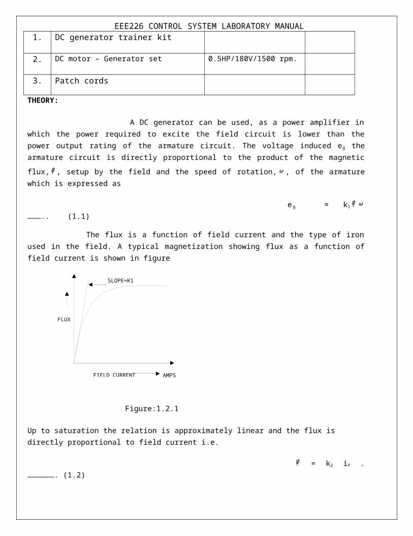
The flux is a function of field current and the type of iron used in the field. A typical magnetization showing flux as a function of field current is shown in figure
Figure:1.2.1
Up to saturation the relation is approximately linear and the flux is directly proportional to field current i.e.
SLOPE=K1
AMPSFIELD CURRENT
FLUX
EEE226 CONTROL SYSTEM LABORATORY MANUAL
φ = k2 if . ………………. (1.2)
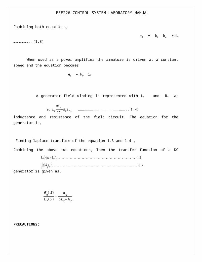
Combining both equations,
eg = k1 k2 ω if ………………...(1.3)
When used as a power amplifier the armature is driven at a constant speed and the equation becomes
eg = kg if
A generator field winding is represented with L f and Rf as inductance and resistance of the field circuit. The equation for the generator is,
Finding laplace transform of the equation 1.3 and 1.4 ,
Combining the above two equations, Then the transfer function of a DC generator is given as,
PRECAUTIONS:
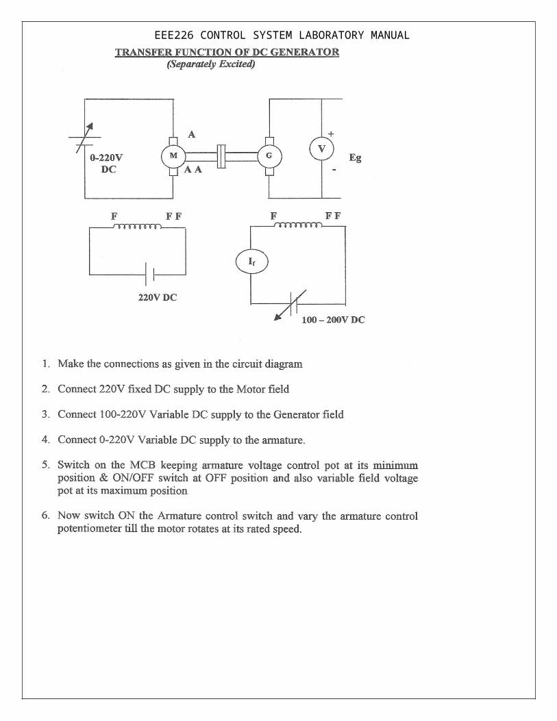
1. At the time of starting the motor field rheostat should be in minimum resistance position and generator
field rheostat should be in maximum resistance position.
2. There should not be any load connected to the generator terminals.
e f=L fdifdt
+R f if .. . …………………………………………. .(1 .4 )
E f ( s)=(sLf +R f ) I f s . . .. .. . .. .. . .. .. .. . .. .. . .. .. . .. .. . .. .. . .. .. . .. .. .. . .. .. . .. .(1.5 )
Eg ( s)=k g I f ( s ) . .. .. . .. .. . .. .. . .. .. .. . .. .. . .. .. . .. .. . .. .. . .. .. . .. .. .. . .. .. . .. .. . .. .. . .(1. 6 )
Eg ( S )E f (S )
=k g
SLf +Rf
EEE226 CONTROL SYSTEM LABORATORY MANUAL
(0-20) A
(0- 300) V

EEE226 CONTROL SYSTEM LABORATORY MANUAL
(0-20) A
(0- 300) V
EEE226 CONTROL SYSTEM LABORATORY MANUAL
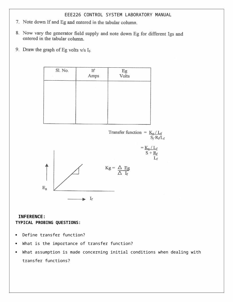
EEE226 CONTROL SYSTEM LABORATORY MANUAL
INFERENCE: TYPICAL PROBING QUESTIONS:
Define transfer function?
What is the importance of transfer function?
What assumption is made concerning initial conditions when dealing with transfer functions?
Why do transfer functions for mechanical networks look identical to transfer functions for electrical
networks?
To what classifications of systems can be transfer function be best applied?
EEE226 CONTROL SYSTEM LABORATORY MANUAL Do the zeros of a system change with a change in gain?
Where are the zeros of the closed loop transfer function?
EEE226 CONTROL SYSTEM LABORATORY MANUAL
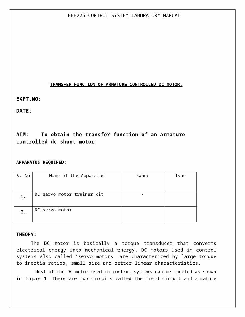
TRANSFER FUNCTION OF ARMATURE CONTROLLED DC MOTOR.
EXPT.NO:
DATE:
AIM: To obtain the transfer function of an armature controlled dc shunt motor.
APPARATUS REQUIRED:
S. No Name of the Apparatus Range Type
1. DC servo motor trainer kit -
2. DC servo motor
THEORY:
The DC motor is basically a torque transducer that converts electrical energy into mechanical energy. DC motors used in control systems also called “servo motors” are characterized by large torque to inertia ratios, small size and better linear characteristics.
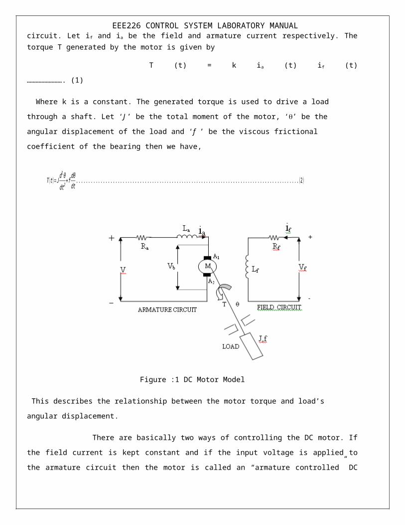
Most of the DC motor used in control systems can be modeled as shown in figure 1. There are two circuits called the field circuit and armature circuit. Let i f and ia be the field and armature current respectively. The torque T generated by the motor is given by
T (t) = k ia (t) if (t) ……………………. (1)
Where k is a constant. The generated torque is used to drive a load through a shaft. Let ‘J ’ be the total
moment of the motor, ‘’ be the angular displacement of the load and ‘f ’ be the viscous frictional coefficient of
the bearing then we have,
T ( t )=J d2θdt 2
+ f dθdt
. .. .. . .. .. .. . .. .. . .. .. . .. .. . .. .. . .. .. . .. .. .. . .. .. . .. .. . .. .. . .. .. . .. .. . .. .. .. . .. .. . .. .. . .. ..(2 )

EEE226 CONTROL SYSTEM LABORATORY MANUAL
Figure :1 DC Motor Model
This describes the relationship between the motor torque and load’s angular displacement.
There are basically two ways of controlling the DC motor. If the field current is kept constant and if the
input voltage is applied to the armature circuit then the motor is called an “armature controlled” DC motor. If
the armature current is kept constant and the input voltage is applied to the field circuit, the motor is called a
“field controlled” DC motor
Consider the dc motor shown in figure 1. If the field current i f is kept constant and the input
voltage is applied to the armature circuit then the motor is an armature controlled dc motor. If i f is constant
equation (1) can be written as,
T (t) = kt ia(t). ------------------------------- (3)
Where kt = kif(t) is a constant. When the motor is driving a load, a back electromotive force
(back emf) voltage Vb, will develop in the armature circuit to resist the applied voltage. The voltage V b (t) is
linearly proportional to the angular velocity (t) of the motor shaft
Vb (t) = kb (t) ----------------------------------- (4)
=kbdθ( t )dt
.. .. . .. .. . .. .. .. . .. .. . .. .. . .. .. . .. .. . .. .. .. . .(5)
EEE226 CONTROL SYSTEM LABORATORY MANUAL
ktRa+Las
1 f+Js
1 s
kb
MOTORLOAD
d/dtT
V +
-
Thus the armature circuit in the figure 1 is described by substitution of equation (3) in (2) and the application
of laplace transform to(2) and (6) give, assuming zero initial conditions,
Eliminating ia, we get the transfer function,
Block diagram of armature controlled dc motor is shown in figure 2
Figure 2 Block diagram of armature controlled dc motor
The equation (9) can be rewritten as,
k t ia ( s)=Js2 θ (s )+fs θ (s ) .. .. . .. .. . .. .. .. . .. .. . .. .. . .. .. . .. .. . .. .. . .. .. .. . .. .. . .. .. . .. .. . .. .. . .. .. . .. .(7)
Ra ia( t )+Ladia ( t )dt
+V b( t )=V a( t )=u( t ). . .. .. . .. .. .. . .. .. . .. .. . .. .. . .. .. . .. .. . .. .. .. . .. .. . .. .. . .. .. .(6 )
G( s )=θ (s )V a( s )
=kt
s [ (Js+ f ) (Ra+ia s)+k t kb ]. .. . .. .. . .. .. . .. .. . .. .. . .. .. . .. .. .. . .. .. . .. .. . .. .. .(9 )
Ra ia( s )+ Lasia( s )+kb sθ (s )=V a( s ). . .. .. . .. .. .. . .. .. . .. .. . .. .. . .. .. . .. .. . .. .. .. . .. .. . .. .. . .. .. .(8 )
θ (s )V a (s )
= K
s [(1+sτ a) (1+sτm)+k tk bRa f ]
. . .. .. . .. .. . .. .. .. . .. .. . .. .. . .. .. . .. .. . .. .. . .. .. .. . .. .. . .. .. . .. .. . .. .. . ..(10 )
EEE226 CONTROL SYSTEM LABORATORY MANUALWhere
PRECAUTIONS:
1. Initially keep all switches in OFF Position.
2. Initially keep voltage adjustment POT (VARIAC) in minimum position.
3. Initially keep Armature and field voltage adjustment POT in minimum position.
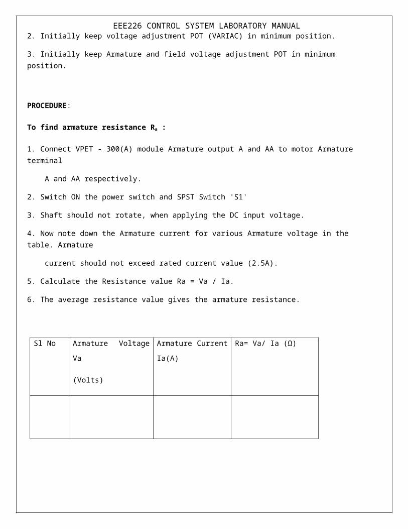
PROCEDURE:
To find armature resistance Ra :
1. Connect VPET - 300(A) module Armature output A and AA to motor Armature terminal
A and AA respectively.
2. Switch ON the power switch and SPST Switch 'S1'
3. Shaft should not rotate, when applying the DC input voltage.
4. Now note down the Armature current for various Armature voltage in the table. Armature
current should not exceed rated current value (2.5A).
5. Calculate the Resistance value Ra = Va / Ia.
6. The average resistance value gives the armature resistance.
Sl No Armature Voltage Va
(Volts)
Armature Current Ia(A) Ra= Va/ Ia (Ω)
K=K tRa f
τm=Jf
τ a=LaRa

EEE226 CONTROL SYSTEM LABORATORY MANUAL
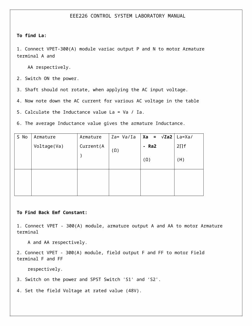
To find La:
1. Connect VPET-300(A) module variac output P and N to motor Armature terminal A and
AA respectively.
2. Switch ON the power.
3. Shaft should not rotate, when applying the AC input voltage.
4. Now note down the AC current for various AC voltage in the table
5. Calculate the Inductance value La = Va / Ia.
6. The average Inductance value gives the armature Inductance.
S No Armature Voltage(Va) Armature
Current(A)
Za= Va/Ia
(Ω)
Xa = √Za2 - Ra2
(Ω)
La=Xa/2∏f
(H)
To Find Back Emf Constant:
1. Connect VPET - 300(A) module, armature output A and AA to motor Armature terminal
A and AA respectively.
2. Connect VPET - 300(A) module, field output F and FF to motor Field terminal F and FF
respectively.
3. Switch on the power and SPST Switch 'S1' and ‘S2'.
4. Set the field Voltage at rated value (48V).
5. Adjust the Armature voltage by using Armature POT. Now note down the Armature

EEE226 CONTROL SYSTEM LABORATORY MANUAL current and speed for various Armature Voltage (up to Motor rated Speed) in the table-5.
6. Plot the graph Eb versus T, model graph is as shown in Fig.1 and calculate the back emf.
S No Armature Voltage(Va) Armature
Current(A)
Eb= V – IaRa (V) Speed N
RPM
ω =
Rad/sec.
Figure 1
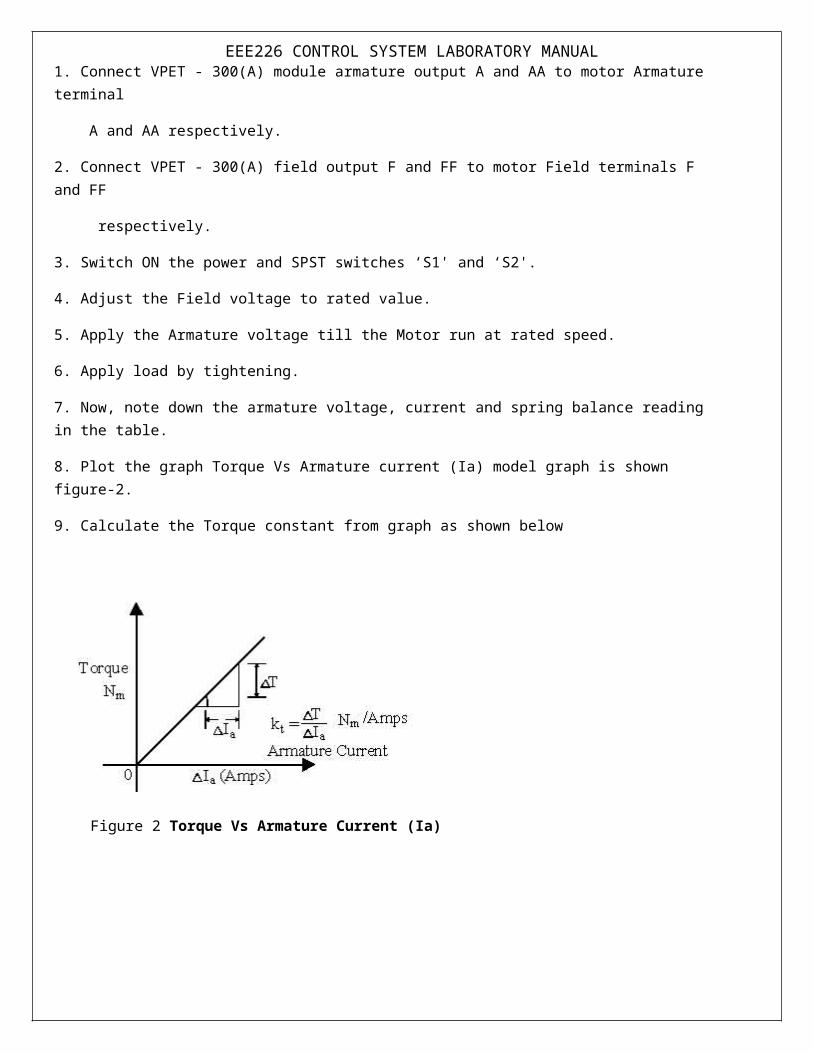
To Find Armature torque constant:
1. Connect VPET - 300(A) module armature output A and AA to motor Armature terminal
A and AA respectively.
2. Connect VPET - 300(A) field output F and FF to motor Field terminals F and FF
respectively.
3. Switch ON the power and SPST switches ‘S1' and ‘S2'.
EEE226 CONTROL SYSTEM LABORATORY MANUAL4. Adjust the Field voltage to rated value.
5. Apply the Armature voltage till the Motor run at rated speed.
6. Apply load by tightening.
7. Now, note down the armature voltage, current and spring balance reading in the table.
8. Plot the graph Torque Vs Armature current (Ia) model graph is shown figure-2.
9. Calculate the Torque constant from graph as shown below
Figure 2 Torque Vs Armature Current (Ia)
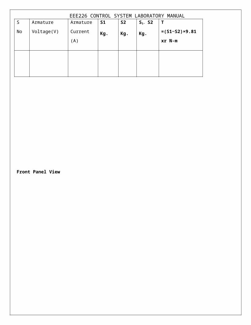
S No Armature
Voltage(V)
Armature
Current (A)
S1
Kg.
S2
Kg.
S1~ S2
Kg.
T =(S1~S2)×9.81 xr
N-m
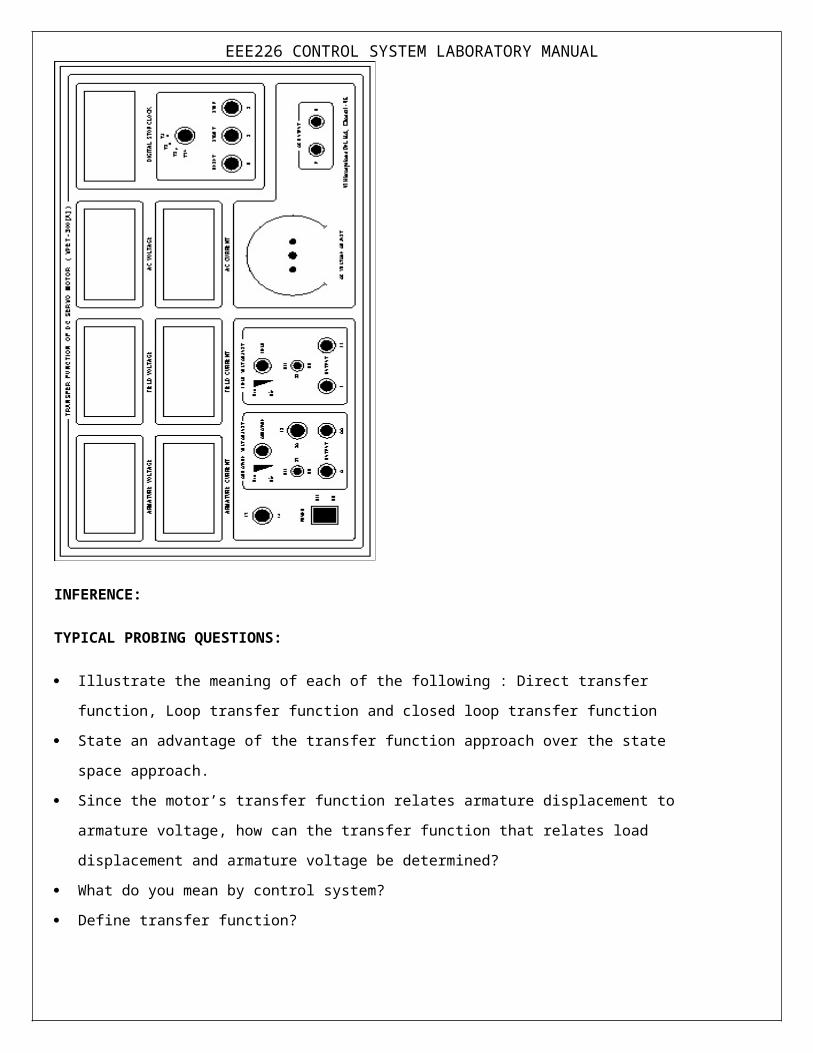
EEE226 CONTROL SYSTEM LABORATORY MANUAL
Front Panel View
INFERENCE:
TYPICAL PROBING QUESTIONS:
Illustrate the meaning of each of the following : Direct transfer function, Loop transfer function and closed
loop transfer function
State an advantage of the transfer function approach over the state space approach.

EEE226 CONTROL SYSTEM LABORATORY MANUAL Since the motor’s transfer function relates armature displacement to armature voltage, how can the
transfer function that relates load displacement and armature voltage be determined?
What do you mean by control system?
Define transfer function?
What is DC servo motor? What are the main parts?
What is servo mechanism?
Is this a closed loop or open loop system .Explain?
What is back EMF?
EEE226 CONTROL SYSTEM LABORATORY MANUAL
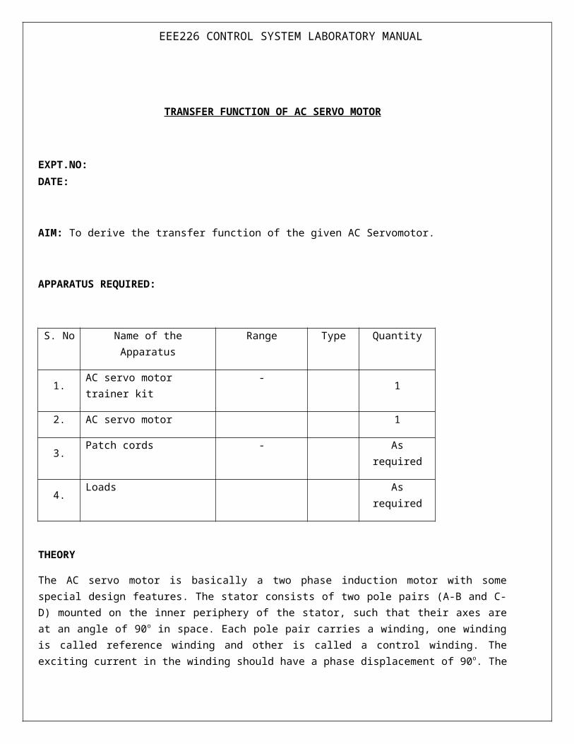
TRANSFER FUNCTION OF AC SERVO MOTOR
EXPT.NO:DATE:
AIM: To derive the transfer function of the given AC Servomotor.
APPARATUS REQUIRED:
S. No Name of the Apparatus Range Type Quantity
1. AC servo motor trainer kit - 1
2. AC servo motor 1
3. Patch cords - As required
4. Loads As required
THEORY
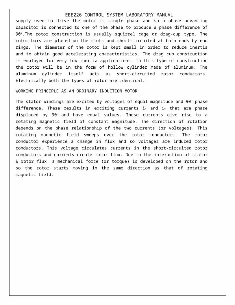
The AC servo motor is basically a two phase induction motor with some special design features. The stator consists of two pole pairs (A-B and C-D) mounted on the inner periphery of the stator, such that their axes are at an angle of 90o in space. Each pole pair carries a winding, one winding is called reference winding and other is called a control winding. The exciting current in the winding should have a phase displacement of 90 o. The supply used to drive the motor is single phase and so a phase advancing capacitor is connected to one of the phase to produce a phase difference of 90o.The rotor construction is usually squirrel cage or drag-cup type. The rotor bars are placed on the slots and short-circuited at both ends by end rings. The diameter of the rotor is kept small in order to reduce inertia and to obtain good accelerating characteristics. The drag cup construction is employed for very low inertia applications. In this type of construction the rotor will be in the form of hollow cylinder made of aluminum. The aluminum cylinder itself acts as short-circuited rotor conductors. Electrically both the types of rotor are identical.
EEE226 CONTROL SYSTEM LABORATORY MANUALWORKING PRINCIPLE AS AN ORDINARY INDUCTION MOTOR
The stator windings are excited by voltages of equal magnitude and 90o phase difference. These results in exciting currents i1 and i2 that are phase displaced by 90o and have equal values. These currents give rise to a rotating magnetic field of constant magnitude. The direction of rotation depends on the phase relationship of the two currents (or voltages). This rotating magnetic field sweeps over the rotor conductors. The rotor conductor experience a change in flux and so voltages are induced rotor conductors. This voltage circulates currents in the short-circuited rotor conductors and currents create rotor flux. Due to the interaction of stator & rotor flux, a mechanical force (or torque) is developed on the rotor and so the rotor starts moving in the same direction as that of rotating magnetic field.
EEE226 CONTROL SYSTEM LABORATORY MANUALFront Panel diagram:
EEE226 CONTROL SYSTEM LABORATORY MANUAL
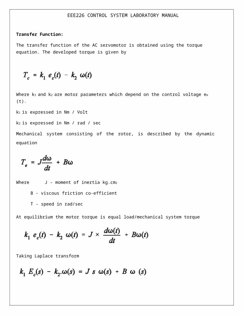
Transfer Function:
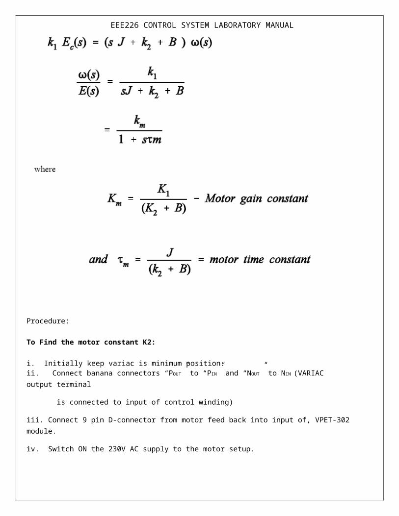
The transfer function of the AC servomotor is obtained using the torque equation. The developed torque is given by
Where k1 and k2 are motor parameters which depend on the control voltage ee (t).
k1 is expressed in Nm / Volt
k2 is expressed in Nm / rad / sec
Mechanical system consisting of the rotor, is described by the dynamic equation
Where J - moment of inertia kg.cm2
B - viscous friction co-efficient
T - speed in rad/sec
At equilibrium the motor torque is equal load/mechanical system torque
Taking Laplace transform
EEE226 CONTROL SYSTEM LABORATORY MANUAL
Procedure:
To Find the motor constant K2:
i. Initially keep variac is minimum position.ii. Connect banana connectors “POUT” to “PIN” and “NOUT” to NIN (VARIAC output terminal
is connected to input of control winding)
iii. Connect 9 pin D-connector from motor feed back into input of, VPET-302 module.
iv. Switch ON the 230V AC supply to the motor setup.
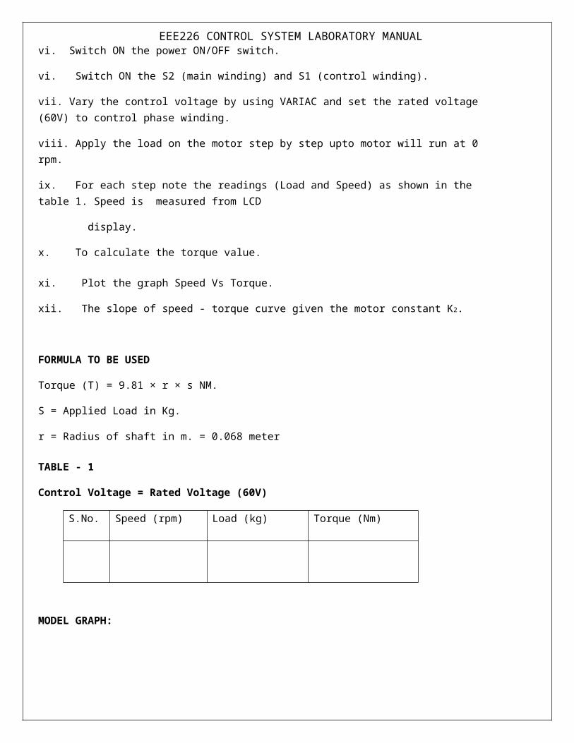
vi. Switch ON the power ON/OFF switch.
vi. Switch ON the S2 (main winding) and S1 (control winding).
EEE226 CONTROL SYSTEM LABORATORY MANUALvii. Vary the control voltage by using VARIAC and set the rated voltage (60V) to control phase winding.
viii. Apply the load on the motor step by step upto motor will run at 0 rpm.
ix. For each step note the readings (Load and Speed) as shown in the table 1. Speed is measured from LCD
display.
x. To calculate the torque value.
xi. Plot the graph Speed Vs Torque.
xii. The slope of speed - torque curve given the motor constant K2.
FORMULA TO BE USED
Torque (T) = 9.81 × r × s NM.
S = Applied Load in Kg.
r = Radius of shaft in m. = 0.068 meter
TABLE - 1
Control Voltage = Rated Voltage (60V)
S.No. Speed (rpm) Load (kg) Torque (Nm)
MODEL GRAPH:

EEE226 CONTROL SYSTEM LABORATORY MANUALii) To determine the motor constant K1:
i. Initially keep variac is minimum position of VPET - 302 module.
ii. Connect banana connectors “POUT” to “PIN” and “NOUT” to NIN (VARIAC output terminal is connected to input of control winding).
iii. Connect 9 pin D-connector from motor feed back into input of VPET-302 module.
iv. Switch ON the 230V AC supply to the motor setup.
v. Switch ON the power ON/OFF switch.
vi. Switch ON the S2 (main winding) and S1 (control windings).
vii. Vary the control voltage by using VARIAC and set the rated voltage (230V) to control phase winding.
viii. Apply the load on the motor step by step up to motor will run at 0 rpm
ix. For each step note the load and control winding voltage is shown in the table 2.
x. To calculate the torque value.
xi. Plot the graph Torque Vs Control voltage.
xii. The slope of torque - control voltage curve gives the motor constant K1
Table 2 Rated speed 200rpm
SNo Load (kg) Control voltage Ec Torque (Nm)

EEE226 CONTROL SYSTEM LABORATORY MANUALMODEL GRAPH
INFERENCE:
TYPICAL PROBING QUESTIONS:
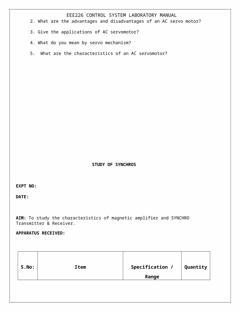
1. What are the main parts of an AC servomotor?
2. What are the advantages and disadvantages of an AC servo motor?
3. Give the applications of AC servomotor?
4. What do you mean by servo mechanism?
5. What are the characteristics of an AC servomotor?
EEE226 CONTROL SYSTEM LABORATORY MANUALSTUDY OF SYNCHROS
EXPT NO:
DATE:
AIM: To study the characteristics of magnetic amplifier and SYNCHRO Transmitter & Receiver.
APPARATUS RECEIVED:
S.No: Item Specification / Range Quantity
1. Synchro transmitter and receiver kit ----- 1
2. Patch chords ----- 1
THEORY:
Synchro is an electromagnetic transducer commonly to convert an angular position of a shaft into electric signal.
Basic synchro is usually called as synchro transmitter. Its construction is similar to that of a three phase alternator. (Refer figure 13.2.1) The stator is of laminated silicon steel and is slotted to accommodate a balanced three phase winding. The rotor is of dump-bell construction and wound with a concentric coil. An a. c. voltage is applied to the rotor winding through slip rings.
Let the a. c. voltage applied be
Vr(t) = Vm sin t
This voltage applied to the rotor of the synchro transmitter cause a flow of magnetizing current in the rotor coil which produces a sinusoidal time varying flux directed along its axis and distributed nearly sinusoidal in the air-gap along stator periphery. Due to transformer action voltages are induced in each of the stator coils. The flux linking with the stator coil is proportional to the cosine of the angle between rotor and stator coil axis and so is the voltage induced in each stator coil.
The induced voltages in the stator coils s1,s2 and s3 with respect to neutral are given as,
EEE226 CONTROL SYSTEM LABORATORY MANUAL
Vs1N=KVm cos ( +120)
Vs2N=KVm sin t cos
Vs3N=KVm sin t cos ( +240)
Where is the angle between the rotor coil axis and stator coil s2 axis.
The terminal voltages of the stator are,
Vs1s2=3KVm sin ( +240) sin t
Vs2s3=3KVm sin ( +120) sin t
Vs3s1=3KVmsin sin t
Thus the input angular position to the synchro transmitter results in a output of three single phase voltages and the magnitude of the voltages are functions of shaft position.
A synchro system consists of two units namely,
1) Synchro transmitter
2) Synchro receiver.
Synchro receiver has almost the same constructional features as transmitter. Initially the winding s2 of the stator of transmitter is positioned for maximum coupling with rotor winding. If V is the voltage in the coil s 2, the coupling between s1 and s3 of the stator and rotor winding is a cosine function. Therefore the effective voltages in these windings are proportional to cos 60 or they are v/2 each. so long as the rotor of the transmitter and receivers remain in this position no current will flow between windings because of the voltage balance.
When the rotor of the transmitter is moved to a new position, the voltage balance is disturbed. This voltage imbalance between the stator winding of transmitter and receiver causes currents to flow producing torque that tends to rotate the rotor of the receiver to a new position. Where the voltage balance is again restored. This balance is restored only if the receiver turns through the same angle as the transmitter and also the direction of the rotation is same as that of the transmitter is same as that of the transmitter.
EEE226 CONTROL SYSTEM LABORATORY MANUAL
R1 R2 R1 R2
S1
S1 S2 S3S1 S2 S3
OFF
ON
PL
MAINS
SW1 SW2
SYNCHROTRANSIMTTTER
SYNCHRORECEIVER
FRONT PANEL VIEW:
PROCEDURE:
To Find the Stator output voltage with respect to the rotor position:
i. Connect Digital Voltmeter across the any two Stator output of Synchro transmitter.
ii. Connect Synchro transmitter stator outputs to corresponding Stator terminals of Synchro
receiver.
iii. Power ‘ON’ the all ON/OFF Switches
iv. Verify the Stator output voltage of 0V at 0 degree, if it is not make 0V at 0 degree to
adjust the pointer of both transmitter and Receiver.
v. Adjust the transmitter rotor position Step by Step.
vi. Now note down the output voltage for various rotor position in the table 1.
vii. Repeat the Same procedure for other pair of Synchro transmitter coils.

EEE226 CONTROL SYSTEM LABORATORY MANUAL
Table-1
Sl No Synchro transmitter
Rotor Position (degree) Stator Output
(1-2)(V)
Stator Output
(2-3)(V)
Stator Output
(1-3)(V)
Model Graph:

EEE226 CONTROL SYSTEM LABORATORY MANUAL
To Study the Rotor position of Synchro transmitter and Receiver:
i. Connect Digital Voltmeter across to the any two Stator output of Synchro transmitter.
ii. Connect Synchro transmitter stator outputs to corresponding Stator terminals of
Synchro receiver.
iii. Power ‘ON’ the all ON/OFF Switches
iv. Verify the Stator output voltage 0V at 0 degree, if it is not make 0V at 0 degree to
adjust the pointer of both transmitter and Receiver.
v. Adjust the transmitter rotor position step by step by using knob
vi. Now note down the rotor position of transmitter and receiver in the table-2.
Table 2
Model Graph:
Output
angular
Position in
degrees
Input angular position in degrees
SL.No Synchro Transmitter Rotor Position(degree)
Synchro Receiver Rotor position (degree)
Error=Rotor position (Transmitter-Receiver)
EEE226 CONTROL SYSTEM LABORATORY MANUALINFERENCE:
TYPICAL PROBING QUESTIONS:
What are the advantages of synchros?
Define angular displacement?
For what purpose synchros are used?
On what principle synchros work?
What is synchro transmitter?
What is synchro control transformer?
Synchro, what type of transducer?