Connection Design Solutions For Wood -Frame Structures...the use of steel connectors in wood -frame...
98
2 Presented by: Jared S. Hensley, P.E. Connection Design Solutions For Wood - Frame Structures Disclaimer: This presentation was developed by a third party and is not funded by WoodWorks or the Softwood Lumber Board.
Transcript of Connection Design Solutions For Wood -Frame Structures...the use of steel connectors in wood -frame...

2
Presented by: Jared S. Hensley, P.E.
Connection Design SolutionsFor Wood-Frame Structures
Disclaimer: This presentation was developed by a third party and is not funded by WoodWorks or the Softwood Lumber Board.

3
Connection Design SolutionsFor Wood-Frame Structures

4
Course DescriptionThis session will feature a discussion of wood connection design and specification, including
common fastener types and where design values can be found for each. Other topics will include the
orthotropic nature of wood and its role in connection design, commodity and specialty connectors, and
the use of steel connectors in wood-frame construction. Discussion will also include
techniques for designing efficient, durable and code-compliant connections, examples of best practice
connection details, and additional resources.
Connection Design SolutionsFor Wood-Frame Structures

5
Learning Objectives1. Discuss code-compliant connection design in the
context of wood and fastener properties.2. Review design processes for dowel bearing
connections in wood structures.3. Demonstrate effective wood connection design,
considering the effects of expansion and shrinkage.
4. Highlight proper specification and detailing of steel connectors used in wood-frame construction.
Connection Design SolutionsFor Wood-Frame Structures

6
Agenda
Key to Connections1. Wood Basics & Connection Philosophy2. Serviceability3. Connection Types
§ Direct Bearing Connections§ Multi-Ply Beam Connections§ Pre-Engineered Connectors
4. Dowel Bearing Connections5. Wood Structural Panel Connections6. Corrosion Resistant Connections

7
Agenda
Key to Connections1. Wood Basics & Connection Philosophy2. Serviceability3. Connection Types
§ Direct Bearing Connections§ Multi-Ply Beam Connections§ Pre-Engineered Connectors
4. Dowel Bearing Connections5. Wood Structural Panel Connections6. Corrosion Resistant Connections

8
Wood Basics & Connection Philosophy
Loads Parallel to Grain vs. Loads Perpendicular to Grain

9
Wood Basics & Connection Philosophy
Compression Parallel To Grain

10
Tension Perpendicular to Grain § Weakest connection in wood
Initiators:§ Notches§ Large diameter
fasteners§ Hanging loads
Wood Basics & Connection Philosophy

11
§ Concentrated loads vs. Group loading§ Large diameter bolts vs. Multiple small fasteners§ Keep scale of fastener small relative to wood
member
Wood Basics & Connection Philosophy

12
Agenda
Key to Connections1. Wood Basics & Connection Philosophy2. Serviceability3. Connection Types
§ Direct Bearing Connections§ Multi-Ply Beam Connections§ Pre-Engineered Connectors
4. Dowel Bearing Connections5. Wood Structural Panel Connections6. Corrosion Resistant Connections

13
Serviceability
USDAFPL-GTR-190
Referenced Publications
APA Publication T300

14
Serviceability
Moisture Changes in Wood § Start as soon as a tree is cut§ Wood shrinks perpendicular to grain
Figure 4-3 :FPL-GTR-190

15
Serviceability
Wood Moves in Varying Environments § Temperature§ Humidity and Moisture

16
Serviceability
§Ambient conditions and Wood Equilibrium Moisture Content (EMC)
§Relative Humidity ≠ EMCEMC of Wood
Figure 4-1 & Table 4-2: FPL-GTR-190

17
Serviceability
§ Ambient conditions and wood EMC
Figure 10-5 & Table 13-1: FPL-GTR-190

18
Serviceability
§Wood EMC at installation is important
Table 13-2: FPL-GTR-190

19
Serviceability
Column Connections to Concrete§ Prevent contact with concrete§ Allow drainage
Figures 15 & 16: APA T300

20
Serviceability
Detailing Considerations: § End grain moisture uptake§ Potential for decay

21
Serviceability
Detailing Considerations: § Avoid tension
perpendicular to grain§ Provide drainage

22
Serviceability
Detailing Considerations: § Allows water collection§ Saturated wood decays

23
Serviceability
Detailing Considerations: § Elevated plates§ Hidden connectors
24
Serviceability
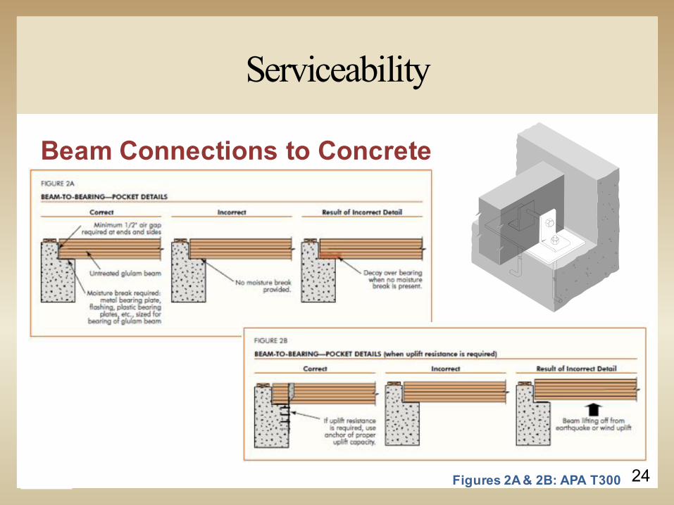
Beam Connections to Concrete
Figures 2A & 2B: APA T300

25
Detailing Considerations:§ Masonry and Grout also contain moisture§ Need 1/2” air gap between wood and masonry
Serviceability

26
Agenda
Key to Connections1. Wood Basics & Connection Philosophy2. Serviceability3. Connection Types
§ Direct Bearing Connections§ Multi-Ply Beam Connections§ Pre-Engineered Connectors
4. Dowel Bearing Connections5. Wood Structural Panel Connections6. Corrosion Resistant Connections

27
Direct Bearing Connections
Its ALL in the Details

28
Direct Bearing Connections
Do Not Bear Directly On Concrete
Most Popular ConnectionsBeam HangerBeam Pocket

29
Direct Bearing Connections
§ Unnecessary Notching§ Creates shear load
concentrations
Detailing Errors to Avoid
§ Exposed End Grain§ Reduces shear strength
Figures 1A & 1B: APA T300

30
Direct Bearing Connections
§ Notch should not exceed 1/10 of beam depth or 3 inches§ Reduced capacity of a 14” beam is 28%
Bottom Notches and Over-Cuts Create Cross Grained Tension Stresses
Figure 1C: APA T300

31
Direct Bearing Connections
Heavy Concentrated Loads§Attach above neutral access§Engages more
Figure 6: APA T300

32
Direct Bearing Connections
Beam to Wall ConnectionsWhat’s easier than setting the beam on something?

33
Beam to Wall Connections§Slotted Hardware§Allows for wood shrinkage
Direct Bearing Connections

34
Direct Bearing Connections
Beam to Beam Connections§ Avoid angles§ Keep bolts low
Figures 3A & 1C: APA T300

35

36
Hybrid Bearing Connections
Direct Bearing Connections
Figure 3E: APA T300

37
Concealed Connections§ Kerf must accommodate steel and weld§ Dowel hole plugged
Direct Bearing Connections

38
Lateral Stability for Deep Beams§ Allows for wood shrinkage§ Restricts lateral movement
Direct Bearing Connections

39
Beam to Column Connections§Side Plates and Caps
§ Allow for shrinkage
Direct Bearing Connections
Figure 10A: APA T300

40
Smaller side plates§ Slotted holes§ Allow wood movement
Direct Bearing Connections
Figure 10B: APA T300

41
Embedded or “Shoed” Column Base
Direct Bearing Connections

42
Bearing plate§ Anchor bolts in bearing plate§ Slotted column end
Angle brackets§ Anchor bolts in brackets
Simple steel dowel§ Bearing plate§ Shear transfer
Direct Bearing Connections

43
Where’s the plate?§ Contractor substituted
grout§ Moisture will wick into
wood§ Potential for decay
Direct Bearing Connections

44
Agenda
Key to Connections1. Wood Basics & Connection Philosophy2. Serviceability3. Connection Types
§ Direct Bearing Connections§ Multi-Ply Beam Connections§ Pre-Engineered Connectors
4. Dowel Bearing Connections5. Wood Structural Panel Connections6. Corrosion Resistant Connections

45
Connection TechniquesMulti-ply Connections

46
Connection TechniquesMulti-ply Connections
Figure 1: APA TT-011C

47
Connection TechniquesMulti-ply Connections
Figure 2: APA TT-011C

48
Connection TechniquesMulti-ply Connections

49
Agenda
Key to Connections1. Wood Basics & Connection Philosophy2. Serviceability3. Connection Types
§ Direct Bearing Connections§ Multi-Ply Beam Connections§ Pre-Engineered Connectors
4. Dowel Bearing Connections5. Wood Structural Panel Connections6. Corrosion Resistant Connections

50
Pre-Engineered Connectors
Joist and Beam Hangers§ Top-Flange and
Face-Mount§ Product specific§ Use correct fastener
(nails or screws)§ Fill all holes§ Ensure proper fastener
penetration

51
Pre-Engineered Connectors

52

53Figure 1h: APA Z725
Pre-Engineered Connectors

54
Pre-Engineered Connectors
Figure 1p: APA Z725

55
Agenda
Key to Connections1. Wood Basics & Connection Philosophy2. Serviceability3. Connection Types
§ Direct Bearing Connections§ Multi-Ply Beam Connections§ Pre-Engineered Connectors
4. Dowel Bearing Connections5. Wood Structural Panel Connections6. Corrosion Resistant Connections

56
Dowel Bearing Connections

57
Power Driven FastenersFour important considerations:§ Nail nomenclature§ Contact§ Thin galvanizing§ Overdriving
Dowel Bearing Connections

58
Nail Nomenclature:§ There is no control over nail nomenclature!
Manufacturers can and will call fasteners anything that they want.
§ 10d does not equal 10d!! § 10d common = .148” diameter§ 10d box = 0.128” diameter§ 10d sinker = .120” diameter
Dowel Bearing Connections

59
Nail Nomenclature:§ Common § Box§ Bring Shank§ Smooth Shank
Nail Specification§ Include pennyweight,
type, diameter and length§ Ex: 10d common
(0.148” shank dia. x 3” shank length)
Dowel Bearing Connections
Figures 5.2 & 5.3: CWC Wood Reference Handbook

60
Power Driven Fastener Considerations§ Contact:
§ Power driven fasteners rely on velocity to drive fasteners and not mass. They do not have the “clamping” action that the last swing of a hammer provides.
§ Thin Galvanizing:§ Power driven fasteners that are “galvanized” are thinly coated to
prevent rusting in the box. The protection is scraped off of the fastener during driving.
§ Overdriving:§ If the “gun” is improperly adjusted, overdriven fasteners can be
expected. Adjusting air pressure is NOT the correct way to prevent over-driven fasteners.
Dowel Bearing Connections

61
Fastener Interchangeability§ International Staple, Nail and Tool Assoc. - ESR-
1539§ Has values for engineered designs for staples and a variety
of other power-driven fasteners§ Available from international staple, nail and tool association
(ISANTA) www.isanta.org708-482-8138
Dowel Bearing Connections

62
Design approach:§Engineered“do the calculations”All variables are accounted for in calculations
Dowel Bearing Connections

63
4 Yield Limit Modes For Wood DesignI - Bearing, II – Pivoting,
III – Fastener Yield, IV – Fastener Yield at two hinge points.
Dowel Bearing Connections
Table 12.3.1A: 2015 NDS

64
§Six Yield Limit equations for single shear
§Four Yield Limit equations for double shear
Dowel Bearing Connections
Figure 11: 2015 NDS

65
Dowel Bearing Connections
2015 NDS Equations

66
Reduction Factors, Rd
Dowel Bearing Connections
Table 12.3.1B: 2015 NDS

67
Yield Limit Equations: Im (12.3-1) and Is (12.3-2)Assuming: DF-G=0.50, D=1.0”, lm=3.5”, ls=1.5”
Table 12.3.32015 NDS
Dowel Bearing Connections

68
Im = 4900 lbs
Is = 2100 lbs
II = 1827 – Governs Design
IIIm = 2664 lbs
IIIs = 2016 lbs
IV = 2846 lbs
Dowel Bearing ConnectionsYield Limit Equations: Im (12.3-1) and Is (12.3-2)
Assuming: DF-G=0.50, D=1.0”, lm=3.5”, ls=1.5”
Values table 12.3.3: 2015 NDS

69
Angle to Grain Adjustment
Hankinson Formula§ Used to resolve wood bearing
strength at any angle to grain§ Assume in previous example that the side member was at
a 45 degree angle. The allowable stress Fes would be calculated using the Hankinson formula to 3210 psi, as opposed to the 5600 psi used in the example.
!"#$ = '())*+,×..')*+,('())*+,)+,1. 2' 3(..')*+,)45+.(2') = 3210:$;
2015 NDSTable 12.3.3

70
NDS Tables 12A to 12T provide a reference for Lateral Design Values in both Single and Double Shear with Wood or Steel Side Plates.
Dowel Bearing Connections

71
Table 12A2015 NDS
Dowel Bearing Connections
Same Assumptions: DF-G=0.50, D=1.0”, lm=3.5”, ls=1.5”

72
Dowel Bearing Connections
Dowel Connection Adjustment Factors
Table 11.3.1: 2015 NDS

73
Dowel Bearing Connections
CD – Load Duration FactorWood capacity is greater for short term loading
Table 2.3.2: 2015 NDS

74
CM - Wet Service Factor for connection Z values
Saturated
19% MC
DryCM 1.0 0.7 0.4 Lateral LoadCM 1.0 0.7 1.0 Withdrawal Load (screws)
§ Bolts§ Lag screws§ Wood screws
fabrication MCin-service MC
Dowel Bearing Connections
Table 11.3.3: 2015 NDS

75
Ct - Temperature FactorUsed for Structural Members that will be exposed to
sustained temperatures up to 150°F
Dowel Bearing Connections
Table 2.3.3: 2015 NDS

76
Cg - Group Action Factor§ Accounts for load distribution within the connection§ Tabulated values in NDS Section 11.3.6§ Can calculate your own group factor if outside the
tabulated table range
Dowel Bearing Connections
Sect. 11.3.6: 2015 NDS

77
Rows are established in direction of load§ 2 or more bolts of same diameter § 2 or more lag screws of same type and size§ 2 or more aligned split ring/shear plate connectors
Dowel Bearing Connections
Figure 11B: 2015 NDS

78
Group Action Factor Equation Method
Where:
Dowel Bearing Connections
EQ 11.3-1: 2015 NDS

79
CD- Geometry Factor
Dowel Bearing Connections
Tables 12.5.1A & 12.5.1B: 2015 NDS

80
CD- Geometry Factor
Dowel Bearing Connections
Tables 12.5.1C & 12.5.1D: 2015 NDS

81
Dowel Bearing Connections

82
Local Fastener Stresses
Net tension:
Row tear-out:
Group tear-out:
nettNT AFZ '' =
∑=
=
=
row
i
i
n
iRTRT
viRT
ZZ
tsFnZ
1
''
min''
netgrouptGT AFZZ
ZnRTRT
−++=−− ''
2'
2' 1
2015 NDS Appendix E
Dowel Bearing Connections

83
End Grain Factor
Diaphragm Factor
Dowel Bearing Connections
Sections 12.5.2 & 12.5.3: 2015 NDS

84
Ctn – Toe-Nail Factor§ Installation per Figure 12A§ 0.83 adjustment for lateral§ 0.67 adjustment for
withdrawal
Dowel Bearing Connections
Figure 12A & Section 12.5.4: 2015 NDS

85
Agenda
Key to Connections1. Wood Basics & Connection Philosophy2. Serviceability3. Connection Types
§ Direct Bearing Connections§ Multi-Ply Beam Connections§ Pre-Engineered Connectors
4. Dowel Bearing Connections5. Wood Structural Panel Connections6. Corrosion Resistant Connections

86
Wood Structural Panel Connections
Nail installation§Overdriving reduces performance
APA TT-012

87
Staggered Nailing§ Code nailing is typically 6” o.c. for edges and 12” o.c. in the
field§ Shear Walls can require tighter nail spacing so staggered
nailing is critical
Wood Structural Panel Connections
Figure F: APA M310

88Nailing not staggered Nailing staggered
Framing
Wood StructuralPanel
Nail
1/8" GapBetween Panels
Nailing not staggered Nailing staggered
Framing
Wood Structural Panel
Nail
1/8″ Gap Between Panels
Wood Structural Panel Connections
Staggered Nailing

89
v
Splitting will not occur perpendicular to grain, no matter how close nails are
Splitting occurs parallel to grain
Staggering
Staggering a line of nails parallel to wood grain minimizes splitting
Wood Structural Panel Connections

90
Shear wall or diaphragm applications with panels applied parallel to supports and/or edge nailed 4" o.c. or closer…
…high risk because the conditions may reduce the standard panel edge gap’s effectiveness in absorbing the panel expansion.
Wood Structural Panel Connections

91
Wood Structural Panel Connections

92
F
B C
G
Shearwall Overturning
Wood Structural Panel Connections

93
Large plate washers (3”x3”x0.229”) prevent splitting of sill plate –
Required for SDC D, E or F (IBC 2305.3.11)
Plate washer
Sill plate
Wood structural panel
Wood Structural Panel Connections
PLAN VIEW

94
Glued Floor System§ Decrease vibration§ Minimize squeaks§ Increase stiffness
Wood Structural Panel Connections

95
Gluing is Not Recommended for bonding wall or roof sheathing to framing
Wood Structural Panel Connections

96
Agenda
Key to Connections1. Wood Basics & Connection Philosophy2. Serviceability3. Connection Types
§ Direct Bearing Connections§ Multi-Ply Beam Connections§ Pre-Engineered Connectors
4. Dowel Bearing Connections5. Wood Structural Panel Connections6. Corrosion Resistant Connections

97
Corrosion Resistant Connections
2015 IBC Requirements
Chapter2304.10
2015 IBC
Figure 1: APA TT-011C
98
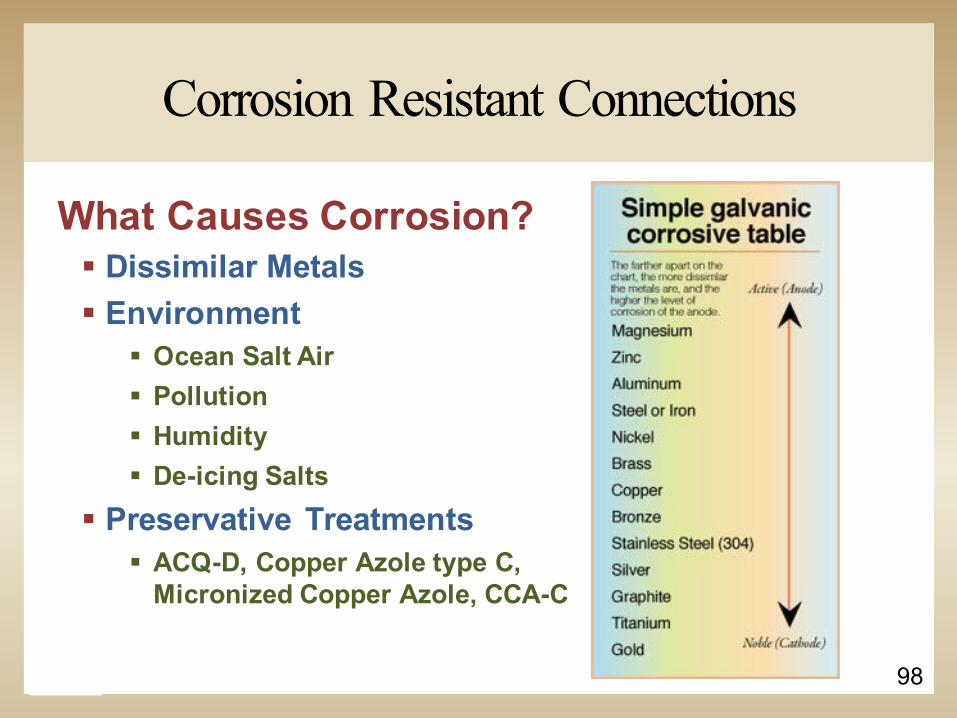
What Causes Corrosion?§ Dissimilar Metals§ Environment
§ Ocean Salt Air§ Pollution§ Humidity§ De-icing Salts
§ Preservative Treatments§ ACQ-D, Copper Azole type C,
Micronized Copper Azole, CCA-C
Corrosion Resistant Connections
99
Questions?
Jared S. Hensley, P.E.APA – The Engineered Wood Association
[email protected] concludes The American Institute of Architects
Continuing Education Systems Course
Can you crack the code?


![Premier Marine Q-Portal · 2017-03-30 · Concrete Block I Masonry Wood Siding - Wood Frame [l Stone Veneer - Wood Frame C] Foundation: Concrete [X Year Built: 1960 Stucco Wood Frame](https://static.fdocuments.in/doc/165x107/5f9385ea1c2ce46d26753432/premier-marine-q-portal-2017-03-30-concrete-block-i-masonry-wood-siding-wood.jpg)