Moisture and Wood-Frame Buildings
20
Building Performance Series No. 1 Moisture and Wood-Frame Buildings Moisture and Wood-Frame Buildings Canadian Wood Council Conseil canadien du bois
Transcript of Moisture and Wood-Frame Buildings
Building Performance Series No. 1
Moisture andWood-Frame
Buildings
Moisture andWood-Frame
Buildings
CanadianWoodCouncil
Conseilcanadiendu bois
Building Performance Bulletin
For more information and links to helpful and relatedinformation sources, visit the Wood Durability website at www.durable-wood.com. A downloadablePDF version of this publication is also available fromthe site.
© 2000 CopyrightCanadian Wood CouncilOttawa, Ontario, Canada
40M1200
Compiled by:Michael Steffen, Walsh Construction Company
Design and production by:Accurate Design & Communication Inc.
Printed by:Lomor Printers Ltd.
Introduction
Throughout history, wherever wood has
been available as a resource, it has found
favor as a building material for its strength,
economy, workability and beauty, and its ability to
last has been demonstrated again and again. From
the ancient temples of Japan and the great stave
churches of Norway to the countless North American
buildings built in the 1800s, wood construction has
proven it can stand the test of time. The art and
technology of wood building, however, has been
changing through time. Can modern wood-frame
buildings perform as well?
Protection of buildings from moisture is an impor-tant design criterion, as important as protection from fire or structural collapse. Designers, buildersand owners are gaining a deeper appreciation for thefunction of the building envelope (exterior walls androof). This includes the performance of windows,doors, siding, sheathing membranes, air and vapourbarriers, sheathing, and framing. The capabilities andcharacteristics of wood and other construction mate-rials must be understood, and then articulated in thedesign of buildings, if proper and durable construc-tion is to be assured.
This guide will help design and construction profes-sionals, and building owners understand moistureissues related to the design and construction ofwood-frame buildings.
The primary objective is to provide ideas and solu-tions to ensure wood-frame buildings perform asexpected. The primary focus of the guide will be on the control of rainwater penetration in exteriorwalls, particularly for climates subject to high mois-ture exposure.
Moisture and Wood-Frame Buildings3
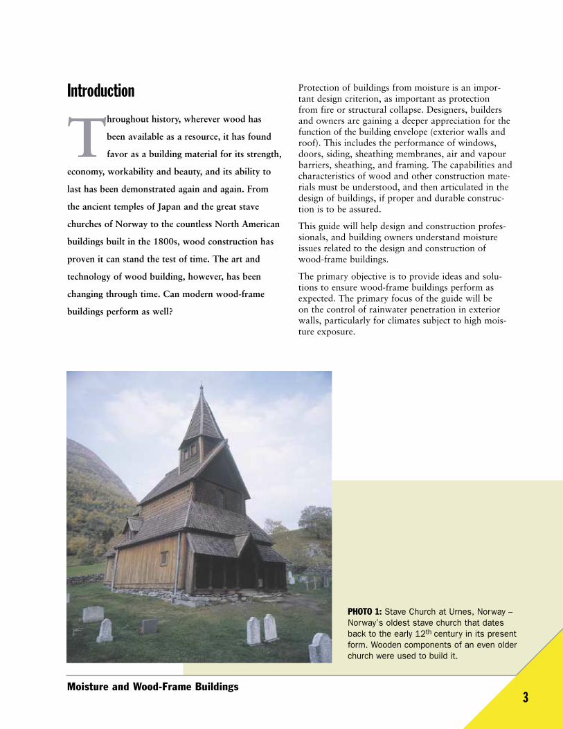
PHOTO 1: Stave Church at Urnes, Norway –Norway’s oldest stave church that datesback to the early 12th century in its presentform. Wooden components of an even olderchurch were used to build it.
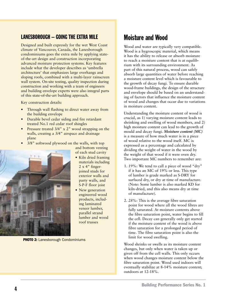
LANESBOROUGH – GOING THE EXTRA MILEDesigned and built expressly for the wet West Coastclimate of Vancouver, Canada, the Lanesboroughcondominiums goes the extra mile by applying state-of-the-art design and construction incorporatingadvanced moisture protection systems. Key featuresinclude what the developer describes as ‘umbrellaarchitecture’ that emphasizes large overhangs andsloping roofs, combined with a multi-layer rainscreenwall system. On-site testing, quality inspection duringconstruction and working with a team of engineersand building envelope experts were also integral partsof this state-of-the-art building approach.
Key construction details:
• Through wall flashing to direct water away fromthe building envelope
• Durable bevel cedar siding and fire retardanttreated No.1 red cedar roof shingles
• Pressure treated 3/4” x 2” wood strapping on thewalls, creating a 3/4” airspace and drainageplane
• 3/8” softwood plywood on the walls, with topand bottom ventingof each stud cavity• Kiln dried framing
materials including2 x 4” finger-joined studs forexterior walls andparty walls, andS-P-F floor joist
• New generationengineered woodproducts, includ-ing laminatedveneer lumber,parallel strandlumber and woodroof trusses
Moisture and WoodWood and water are typically very compatible.Wood is a hygroscopic material, which means it has the ability to release or absorb moisture to reach a moisture content that is at equilib-rium with its surrounding environment. As part of this natural process, wood can safelyabsorb large quantities of water before reachinga moisture content level which is favourable tothe growth of decay fungi. To ensure durablewood-frame buildings, the design of the structureand envelope should be based on an understand-ing of factors that influence the moisture contentof wood and changes that occur due to variationsin moisture content.
Understanding the moisture content of wood iscrucial, as 1) varying moisture content leads toshrinking and swelling of wood members, and 2)high moisture content can lead to the growth ofmould and decay fungi. Moisture content (MC)is a measure of how much water is in a piece of wood relative to the wood itself. MC isexpressed as a percentage and calculated bydividing the weight of water in the wood by the weight of that wood if it were oven dry. Two important MC numbers to remember are:
1. 19%: We tend to call a piece of wood “dry”if it has an MC of 19% or less. This type of lumber is grade marked as S-DRY for surfaced dry, or dry at time of manufacture.(Note: Some lumber is also marked KD forkiln-dried, and this also means dry at time of manufacture).
2. 28%: This is the average fibre saturationpoint for wood where all the wood fibres arefully saturated. At moisture contents abovethe fibre saturation point, water begins to fillthe cell. Decay can generally only get startedif the moisture content of the wood is abovefibre saturation for a prolonged period oftime. The fibre saturation point is also thelimit for wood swelling.
Wood shrinks or swells as its moisture contentchanges, but only when water is taken up orgiven off from the cell walls. This only occurswhen wood changes moisture content below thefibre saturation point. Wood used indoors willeventually stabilize at 8-14% moisture content;outdoors at 12-18%.
Building Performance Series No. 14
PHOTO 2: Lanesborough Condominiums
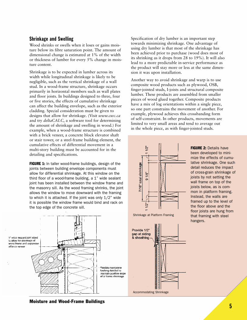
Shrinkage and SwellingWood shrinks or swells when it loses or gains mois-ture below its fibre saturation point. The amount ofdimensional change is estimated at 1% of the widthor thickness of lumber for every 5% change in mois-ture content.
Shrinkage is to be expected in lumber across itswidth while longitudinal shrinkage is likely to benegligible, such as the vertical shrinkage of a wallstud. In a wood-frame structure, shrinkage occursprimarily in horizontal members such as wall platesand floor joists. In buildings designed to three, fouror five stories, the effects of cumulative shrinkagecan affect the building envelope, such as the exteriorcladding. Special consideration must be given todesigns that allow for shrinkage. (Visit www.cwc.caand try deltaCALC, a software tool for determiningthe amount of shrinkage and swelling in wood.) Forexample, when a wood-frame structure is combinedwith a brick veneer, a concrete block elevator shaftor stair tower, or a steel-frame building element, thecumulative effects of differential movement in amulti-story building must be accounted for in thedetailing and specifications.
FIGURE 1: In taller wood-frame buildings, design of thejoints between building envelope components mustallow for differential shrinkage. At this window on thethird floor of a wood-frame building, a 1” wide sealantjoint has been installed between the window frame andthe masonry sill. As the wood framing shrinks, the jointallows the window to move downward with the framingto which it is attached. If the joint was only 1/2” wideit is possible the window frame would bind and rack onthe top edge of the concrete sill.
Specification of dry lumber is an important steptowards minimizing shrinkage. One advantage ofusing dry lumber is that most of the shrinkage hasbeen achieved prior to purchase (wood does most ofits shrinking as it drops from 28 to 19%). It will alsolead to a more predictable in-service performance asthe product will stay more or less at the same dimen-sion it was upon installation.
Another way to avoid shrinkage and warp is to usecomposite wood products such as plywood, OSB,finger-jointed studs, I-joists and structural compositelumber. These products are assembled from smallerpieces of wood glued together. Composite productshave a mix of log orientations within a single piece,so one part constrains the movement of another. Forexample, plywood achieves this crossbanding form of self-constraint. In other products, movements arelimited to very small areas and tend to average out in the whole piece, as with finger-jointed studs.
Moisture and Wood-Frame Buildings5
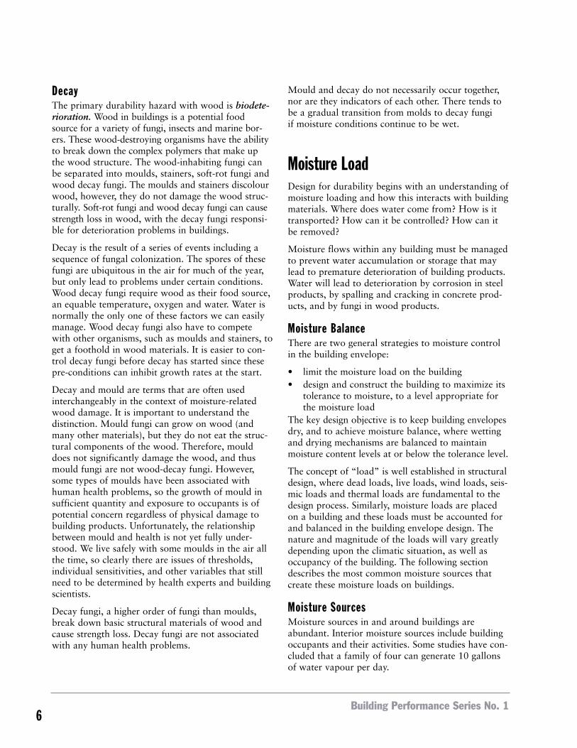
Shrinkage at Platform Framing
FIGURE 2: Details havebeen developed to mini-mize the effects of cumu-lative shrinkage. One suchdetail reduces the impactof cross-grain shrinkage ofjoists by not setting thewall frame on top of thejoists below, as is com-mon in platform framing.Instead, the walls areframed up to the level ofthe floor above and thefloor joists are hung fromthat framing with steelhangers.
Accommodating Shrinkage
Building Performance Series No. 16
DecayThe primary durability hazard with wood is biodete-rioration. Wood in buildings is a potential foodsource for a variety of fungi, insects and marine bor-ers. These wood-destroying organisms have the abilityto break down the complex polymers that make upthe wood structure. The wood-inhabiting fungi canbe separated into moulds, stainers, soft-rot fungi andwood decay fungi. The moulds and stainers discolourwood, however, they do not damage the wood struc-turally. Soft-rot fungi and wood decay fungi can causestrength loss in wood, with the decay fungi responsi-ble for deterioration problems in buildings.
Decay is the result of a series of events including asequence of fungal colonization. The spores of thesefungi are ubiquitous in the air for much of the year,but only lead to problems under certain conditions.Wood decay fungi require wood as their food source,an equable temperature, oxygen and water. Water isnormally the only one of these factors we can easilymanage. Wood decay fungi also have to competewith other organisms, such as moulds and stainers, toget a foothold in wood materials. It is easier to con-trol decay fungi before decay has started since thesepre-conditions can inhibit growth rates at the start.
Decay and mould are terms that are often used interchangeably in the context of moisture-relatedwood damage. It is important to understand the distinction. Mould fungi can grow on wood (andmany other materials), but they do not eat the struc-tural components of the wood. Therefore, moulddoes not significantly damage the wood, and thusmould fungi are not wood-decay fungi. However,some types of moulds have been associated withhuman health problems, so the growth of mould insufficient quantity and exposure to occupants is ofpotential concern regardless of physical damage tobuilding products. Unfortunately, the relationshipbetween mould and health is not yet fully under-stood. We live safely with some moulds in the air allthe time, so clearly there are issues of thresholds,individual sensitivities, and other variables that stillneed to be determined by health experts and buildingscientists.
Decay fungi, a higher order of fungi than moulds,break down basic structural materials of wood andcause strength loss. Decay fungi are not associatedwith any human health problems.
Mould and decay do not necessarily occur together,nor are they indicators of each other. There tends tobe a gradual transition from molds to decay fungi if moisture conditions continue to be wet.
Moisture LoadDesign for durability begins with an understanding ofmoisture loading and how this interacts with buildingmaterials. Where does water come from? How is ittransported? How can it be controlled? How can itbe removed?
Moisture flows within any building must be managedto prevent water accumulation or storage that maylead to premature deterioration of building products.Water will lead to deterioration by corrosion in steelproducts, by spalling and cracking in concrete prod-ucts, and by fungi in wood products.
Moisture BalanceThere are two general strategies to moisture controlin the building envelope:
• limit the moisture load on the building• design and construct the building to maximize its
tolerance to moisture, to a level appropriate forthe moisture load
The key design objective is to keep building envelopesdry, and to achieve moisture balance, where wettingand drying mechanisms are balanced to maintainmoisture content levels at or below the tolerance level.
The concept of “load” is well established in structuraldesign, where dead loads, live loads, wind loads, seis-mic loads and thermal loads are fundamental to thedesign process. Similarly, moisture loads are placedon a building and these loads must be accounted forand balanced in the building envelope design. Thenature and magnitude of the loads will vary greatlydepending upon the climatic situation, as well asoccupancy of the building. The following sectiondescribes the most common moisture sources thatcreate these moisture loads on buildings.
Moisture SourcesMoisture sources in and around buildings are abundant. Interior moisture sources include buildingoccupants and their activities. Some studies have con-cluded that a family of four can generate 10 gallonsof water vapour per day.
Moisture and Wood-Frame Buildings7
Exterior moisture sources include precipitation, irrigation systems and groundwater. Water vapour is also present in the exterior environment and may significantly affect the building envelope insome climates.
An additional source of moisture is often called construction moisture. This is water contained inconcrete, grout, wood and other building materialsduring the time of construction. This amount ofmoisture can be substantial and allowance must bemade for drying before or after the building envelopeis enclosed.
Rainwater, especially wind driven, is the moisturesource that impacts the performance of the envelopemost, and is the focus of this guide.
Moisture Transport Mechanisms The migration of moisture into and through buildingassemblies generally takes place by any of four mois-ture transport mechanisms: liquid flow, capillarity,convection or diffusion. Liquid flow and capillarityinto the building envelope occur primarily with exterior source moisture such as rainwater andgroundwater, whereas movement of moisture intothe building envelope by diffusion or air movementcan occur with interior or exterior source moisture.
Liquid flow is the movement of water under the influence of a driving force (such as gravity, or suction caused by air pressure differences).
Capillarity is the movement of liquid water inporous materials resulting from surface tensionforces. Capillarity, or capillary suction, can also occurin the small space created between two materials.
Air movement refers to the movement of watervapour resulting from air flow through spaces and materials.
Diffusion is the movement of water vapour resultingfrom a vapour pressure difference.
Of the four transport mechanisms, liquid flow andcapillarity are the most significant. Thus, it is notsurprising that rain penetration and groundwatercontrol has been the primary focus of builders anddesigners for generations. Air movement and vapourdiffusion are important, though less significant andobvious contributors to moisture problems.
ExposureThe design of building envelope assemblies must bebased on an evaluation of the probable exposure tomoisture. For exterior walls, design exposure, mois-ture load, is primarily a function of three conditions:
• Macro-climate: regional climatic norms• Micro-climate: site-specific factors such as siting,
solar exposure, wind exposure, and relationshipto surrounding buildings, vegetation and terrain
• Building design: protective features such as overhangs & cornices
The levels of exposure can vary significantly on asingle building, and the design of exterior wallassemblies can reflect these differences. There is significant research underway to characterize thedegree of exposure in different climates.
As an example of climate classification, building scientist Joseph Lstiburek has developed the conceptof limit states as applied to building durability.Furthering the notion that concepts of load and loadresistance are as applicable to moisture design asthey are to structural design, Lstiburek writes: “Weshould consider rain, temperature, humidity and theinterior climate as environmental loads, and limitstates as decay, mould and corrosion.”
Lstiburek proposes that building envelopes andmechanical systems should be designed relative to a set of hazard classes that, taken together, definethe environmental load:
• Hygro-Thermal Regions- Severe-Cold- Cold- Mixed-Humid- Hot-Humid- Hot-Dry/Mixed-Dry
• Rain Exposure Zones- Extreme: over 60 inches annual precipitation- High: 40 to 60 inches annual precipitation- Moderate: 20 to 40 inches annual precipitation- Low: under 20 inches annual precipitation
• Interior Climate Classes- Uncontrolled (warehouses, garages, storage
rooms)- Moderated (houses, apartments, offices,
schools, commercial and retail spaces)- Controlled (hospitals, museums, swimming
pool enclosures and computer facilities)
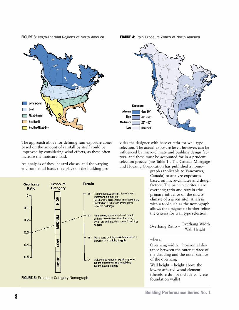
The approach above for defining rain exposure zonesbased on the amount of rainfall by itself could beimproved by considering wind effects, as these oftenincrease the moisture load.
An analysis of these hazard classes and the varyingenvironmental loads they place on the building pro-
vides the designer with base criteria for wall typeselection. The actual exposure level, however, can beinfluenced by micro-climate and building design fac-tors, and these must be accounted for in a prudentselection process (see Table 1). The Canada Mortgageand Housing Corporation has published a nomo-
graph (applicable to Vancouver,Canada) to analyze exposuresbased on micro-climates and designfactors. The principle criteria areoverhang ratio and terrain (the primary influence on the micro-climate of a given site). Analysiswith a tool such as the nomographallows the designer to further refinethe criteria for wall type selection.
where,
Overhang width = horizontal dis-tance between the outer surface ofthe cladding and the outer surfaceof the overhang
Wall height = height above thelowest affected wood element(therefore do not include concretefoundation walls)
Building Performance Series No. 18
Severe-Cold
Cold
Mixed-Humid
Hot-Humid
Hot-Dry/Mixed-Dry
Over 60”
40” - 60”
20” - 40”
Under 20”
Extreme
High
Moderate
Low
Exposure
FIGURE 3: Hygro-Thermal Regions of North America FIGURE 4: Rain Exposure Zones of North America
FIGURE 5: Exposure Category Nomograph
Overhang Ratio = Overhang Width
Wall Height
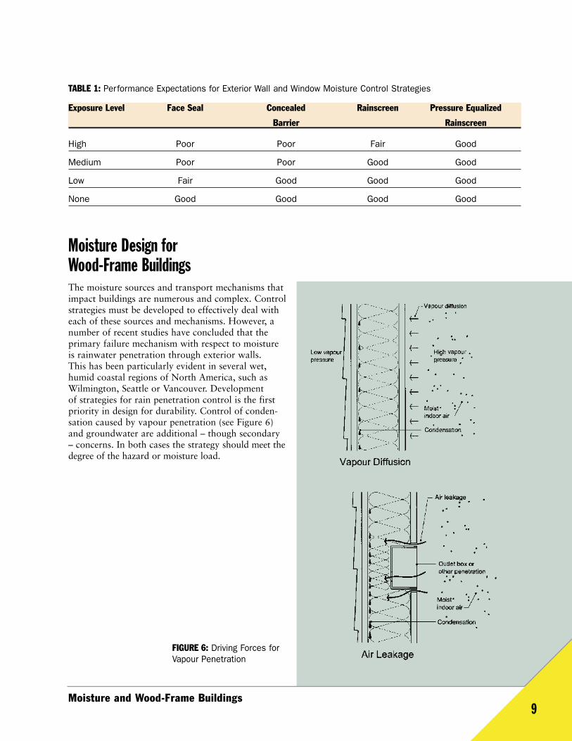
Moisture Design for Wood-Frame BuildingsThe moisture sources and transport mechanisms thatimpact buildings are numerous and complex. Controlstrategies must be developed to effectively deal witheach of these sources and mechanisms. However, anumber of recent studies have concluded that the primary failure mechanism with respect to moistureis rainwater penetration through exterior walls. This has been particularly evident in several wet,humid coastal regions of North America, such asWilmington, Seattle or Vancouver. Development of strategies for rain penetration control is the firstpriority in design for durability. Control of conden-sation caused by vapour penetration (see Figure 6)and groundwater are additional – though secondary– concerns. In both cases the strategy should meet thedegree of the hazard or moisture load.
Moisture and Wood-Frame Buildings9
TABLE 1: Performance Expectations for Exterior Wall and Window Moisture Control Strategies
Exposure Level Face Seal Concealed Rainscreen Pressure Equalized
Barrier Rainscreen
High Poor Poor Fair Good
Medium Poor Poor Good Good
Low Fair Good Good Good
None Good Good Good Good
FIGURE 6: Driving Forces forVapour Penetration
Rain Penetration ControlThere are two general strategies for rain penetrationcontrol:
• minimize the amount of rainwater contacting the building surfaces and assemblies
• manage the rainwater deposited on or withinassemblies
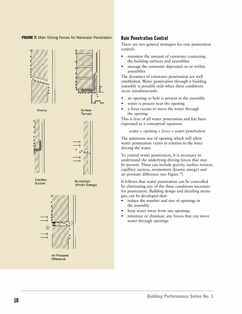
The dynamics of rainwater penetration are wellestablished. Water penetration through a buildingassembly is possible only when three conditionsoccur simultaneously:
• an opening or hole is present in the assembly • water is present near the opening• a force occurs to move the water through
the opening This is true of all water penetration and has beenexpressed as a conceptual equation:
water + opening + force = water penetration
The minimum size of opening which will allow water penetration varies in relation to the force driving the water.
To control water penetration, it is necessary tounderstand the underlying driving forces that may be present. These can include gravity, surface tension,capillary suction, momentum (kinetic energy) andair pressure difference (see Figure 7)
It follows that water penetration can be controlledby eliminating any of the three conditions necessaryfor penetration. Building design and detailing strate-gies can be developed that:• reduce the number and size of openings in
the assembly• keep water away from any openings• minimize or eliminate any forces that can move
water through openings
Building Performance Series No. 110
FIGURE 7: Main Driving Forces for Rainwater Penetration
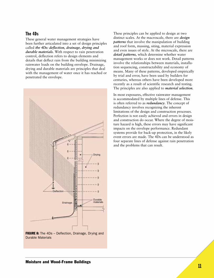
The 4DsThese general water management strategies havebeen further articulated into a set of design principlescalled the 4Ds: deflection, drainage, drying anddurable materials. With respect to rain penetrationcontrol, deflection refers to design elements anddetails that deflect rain from the building minimizingrainwater loads on the building envelope. Drainage,drying and durable materials are principles that dealwith the management of water once it has reached orpenetrated the envelope.
These principles can be applied to design at two distinct scales. At the macroscale, there are designpatterns that involve the manipulation of buildingand roof form, massing, siting, material expressionand even issues of style. At the microscale, there aredetail patterns, which determine whether water management works or does not work. Detail patternsinvolve the relationships between materials, installa-tion sequencing, constructability and economy ofmeans. Many of these patterns, developed empiricallyby trial and error, have been used by builders forcenturies, whereas others have been developed morerecently as a result of scientific research and testing.The principles are also applied to material selection.
In most exposures, effective rainwater management is accommodated by multiple lines of defense. This is often referred to as redundancy. The concept ofredundancy involves recognizing the inherent limitations of the design and construction processes.Perfection is not easily achieved and errors in designand construction do occur. Where the degree of mois-ture hazard is high, these errors may have significantimpacts on the envelope performance. Redundant systems provide for back-up protection, in the likelyevent errors are made. The 4Ds can be understood asfour separate lines of defense against rain penetrationand the problems that can result.
Moisture and Wood-Frame Buildings11
FIGURE 8: The 4Ds – Deflection, Drainage, Drying andDurable Materials
0
102030405060708090
100
0 1-300 301-600 over 600
Perc
ent o
f All W
alls W
hich
Have
Pro
blem
s
Width of Overhang Above Wall, mm
FIGURE 9: Four Lines of Defense – Redundancy isdesigned into exterior wall systems by providing multiple lines of defense. Imagine a hundred raindropsfalling on a building (on a windy day). Approximately 92 drops will be deflected by the pitched roof, over-hangs, projecting sills, and the face of the cladding; 7 drops will be drained behind the cladding over themoisture barrier, then returned to the exterior; and 1 drop will be dried by vapour diffusion and air movement. Where it is anticipated that moisture may accumulate on wood materials in the assembly,that moisture will be “held” safely by durable materials –in this case a pressure-treated sill plate – until it isremoved by drying.
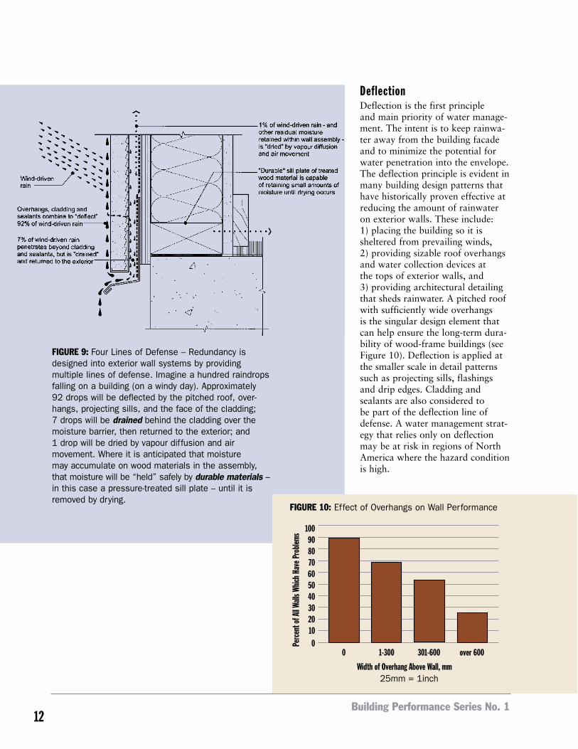
DeflectionDeflection is the first principle and main priority of water manage-ment. The intent is to keep rainwa-ter away from the building facadeand to minimize the potential forwater penetration into the envelope.The deflection principle is evident inmany building design patterns thathave historically proven effective atreducing the amount of rainwateron exterior walls. These include: 1) placing the building so it is sheltered from prevailing winds, 2) providing sizable roof overhangsand water collection devices at the tops of exterior walls, and 3) providing architectural detailingthat sheds rainwater. A pitched roofwith sufficiently wide overhangs is the singular design element thatcan help ensure the long-term dura-bility of wood-frame buildings (seeFigure 10). Deflection is applied atthe smaller scale in detail patternssuch as projecting sills, flashingsand drip edges. Cladding andsealants are also considered to be part of the deflection line ofdefense. A water management strat-egy that relies only on deflectionmay be at risk in regions of NorthAmerica where the hazard conditionis high.
Building Performance Series No. 112
FIGURE 10: Effect of Overhangs on Wall Performance
25mm = 1inch
Moisture and Wood-Frame Buildings13
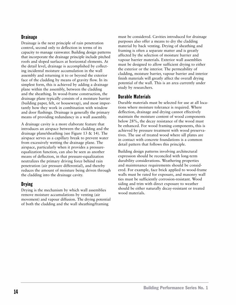
PHOTO 3: Girvin Cabin – This wood-frame studio and house located onDecatur Island, Washington uses pronounced overhangs that are bothfunctional by deflecting rainwater froma window wall and architectural to suitthe surrounding environment.
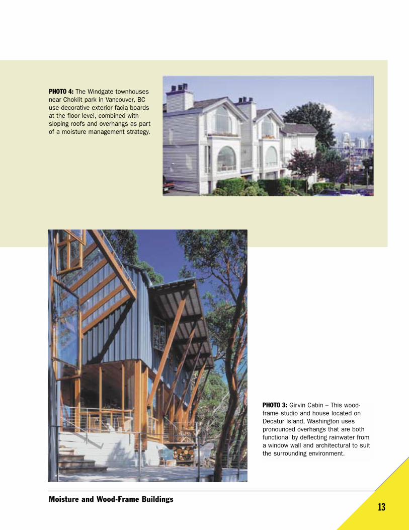
PHOTO 4: The Windgate townhousesnear Choklit park in Vancouver, BCuse decorative exterior facia boardsat the floor level, combined withsloping roofs and overhangs as partof a moisture management strategy.
DrainageDrainage is the next principle of rain penetrationcontrol, second only to deflection in terms of itscapacity to manage rainwater. Building design patternsthat incorporate the drainage principle include pitchedroofs and sloped surfaces at horizontal elements. Atthe detail level, drainage is accomplished by collect-ing incidental moisture accumulation in the wallassembly and returning it to or beyond the exteriorface of the cladding by means of gravity flow. In itssimplest form, this is achieved by adding a drainageplane within the assembly, between the cladding and the sheathing. In wood-frame construction, thedrainage plane typically consists of a moisture barrier(building paper, felt, or housewrap), and most impor-tantly how they work in combination with windowand door flashings. Drainage is generally the primarymeans of providing redundancy in a wall assembly.
A drainage cavity is a more elaborate feature thatintroduces an airspace between the cladding and thedrainage plane/sheathing (see Figure 13 & 14). Theairspace serves as a capillary break to prevent waterfrom excessively wetting the drainage plane. The airspace, particularly when it provides a pressure-equalization function, can also be seen as anothermeans of deflection, in that pressure-equalizationneutralizes the primary driving force behind rainpenetration (air pressure differential), and therebyreduces the amount of moisture being driven throughthe cladding into the drainage cavity.
DryingDrying is the mechanism by which wall assembliesremove moisture accumulations by venting (airmovement) and vapour diffusion. The drying potentialof both the cladding and the wall sheathing/framing
must be considered. Cavities introduced for drainagepurposes also offer a means to dry the claddingmaterial by back venting. Drying of sheathing andframing is often a separate matter and is greatlyaffected by the selection of moisture barrier andvapour barrier materials. Exterior wall assembliesmust be designed to allow sufficient drying to eitherthe exterior or the interior. The permeability ofcladding, moisture barrier, vapour barrier and interiorfinish materials will greatly affect the overall dryingpotential of the wall. This is an area currently understudy by researchers.
Durable MaterialsDurable materials must be selected for use at all loca-tions where moisture tolerance is required. Wheredeflection, drainage and drying cannot effectivelymaintain the moisture content of wood componentsbelow 28%, the decay resistance of the wood mustbe enhanced. For wood framing components, this isachieved by pressure treatment with wood preserva-tives. The use of treated wood where sill plates are in contact with concrete foundations is a commondetail pattern that follows this principle.
Building design patterns involving architecturalexpression should be reconciled with long-term durability considerations. Weathering properties and maintenance requirements should be consid-ered. For example, face brick applied to wood-framewalls must be rated for exposure, and masonry wallties must be sufficiently corrosion-resistant. Woodsiding and trim with direct exposure to weathershould be either naturally decay-resistant or treatedwood materials.
Building Performance Series No. 114
RAINWATER MANAGEMENT STRATEGIES FOREXTERIOR WALLS – PUTTING IT ALL TOGETHERThere are three basic exterior wall type options forwood-frame buildings, each based on a distinct con-ceptual strategy for rainwater management: face seal,concealed barrier and rainscreen. When designingexterior walls for a given building, there is a need to select an appropriate system and be consistentthrough the design and detailing phase and to clearly communicate the details of the system to the construction team.
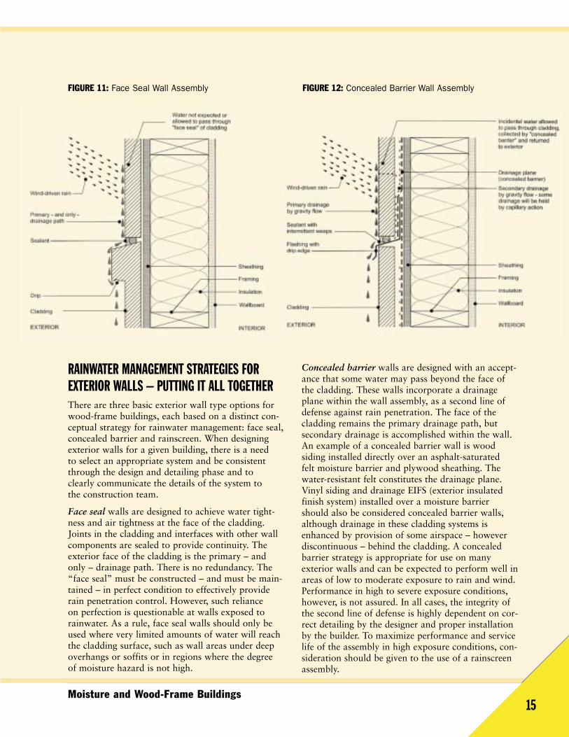
Face seal walls are designed to achieve water tight-ness and air tightness at the face of the cladding.Joints in the cladding and interfaces with other wallcomponents are sealed to provide continuity. Theexterior face of the cladding is the primary – andonly – drainage path. There is no redundancy. The“face seal” must be constructed – and must be main-tained – in perfect condition to effectively providerain penetration control. However, such reliance on perfection is questionable at walls exposed torainwater. As a rule, face seal walls should only beused where very limited amounts of water will reachthe cladding surface, such as wall areas under deepoverhangs or soffits or in regions where the degree of moisture hazard is not high.
Concealed barrier walls are designed with an accept-ance that some water may pass beyond the face ofthe cladding. These walls incorporate a drainageplane within the wall assembly, as a second line ofdefense against rain penetration. The face of thecladding remains the primary drainage path, but secondary drainage is accomplished within the wall.An example of a concealed barrier wall is wood siding installed directly over an asphalt-saturated felt moisture barrier and plywood sheathing. Thewater-resistant felt constitutes the drainage plane.Vinyl siding and drainage EIFS (exterior insulatedfinish system) installed over a moisture barriershould also be considered concealed barrier walls,although drainage in these cladding systems isenhanced by provision of some airspace – howeverdiscontinuous – behind the cladding. A concealedbarrier strategy is appropriate for use on many exterior walls and can be expected to perform well inareas of low to moderate exposure to rain and wind.Performance in high to severe exposure conditions,however, is not assured. In all cases, the integrity ofthe second line of defense is highly dependent on cor-rect detailing by the designer and proper installationby the builder. To maximize performance and servicelife of the assembly in high exposure conditions, con-sideration should be given to the use of a rainscreenassembly.
Moisture and Wood-Frame Buildings
FIGURE 12: Concealed Barrier Wall AssemblyFIGURE 11: Face Seal Wall Assembly
15
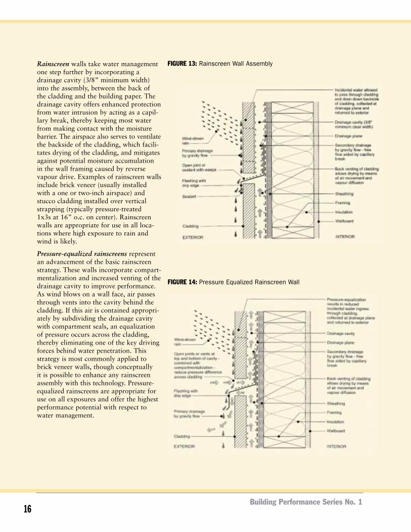
Rainscreen walls take water managementone step further by incorporating adrainage cavity (3/8” minimum width)into the assembly, between the back of the cladding and the building paper. Thedrainage cavity offers enhanced protectionfrom water intrusion by acting as a capil-lary break, thereby keeping most waterfrom making contact with the moisturebarrier. The airspace also serves to ventilatethe backside of the cladding, which facili-tates drying of the cladding, and mitigatesagainst potential moisture accumulation in the wall framing caused by reversevapour drive. Examples of rainscreen wallsinclude brick veneer (usually installedwith a one or two-inch airspace) and stucco cladding installed over verticalstrapping (typically pressure-treated 1x3s at 16” o.c. on center). Rainscreenwalls are appropriate for use in all loca-tions where high exposure to rain andwind is likely.
Pressure-equalized rainscreens representan advancement of the basic rainscreenstrategy. These walls incorporate compart-mentalization and increased venting of thedrainage cavity to improve performance.As wind blows on a wall face, air passesthrough vents into the cavity behind thecladding. If this air is contained appropri-ately by subdividing the drainage cavitywith compartment seals, an equalizationof pressure occurs across the cladding,thereby eliminating one of the key drivingforces behind water penetration. Thisstrategy is most commonly applied tobrick veneer walls, though conceptually it is possible to enhance any rainscreenassembly with this technology. Pressure-equalized rainscreens are appropriate foruse on all exposures and offer the highestperformance potential with respect towater management.
Building Performance Series No. 116
FIGURE 13: Rainscreen Wall Assembly
FIGURE 14: Pressure Equalized Rainscreen Wall
Moisture and Wood-Frame Buildings17
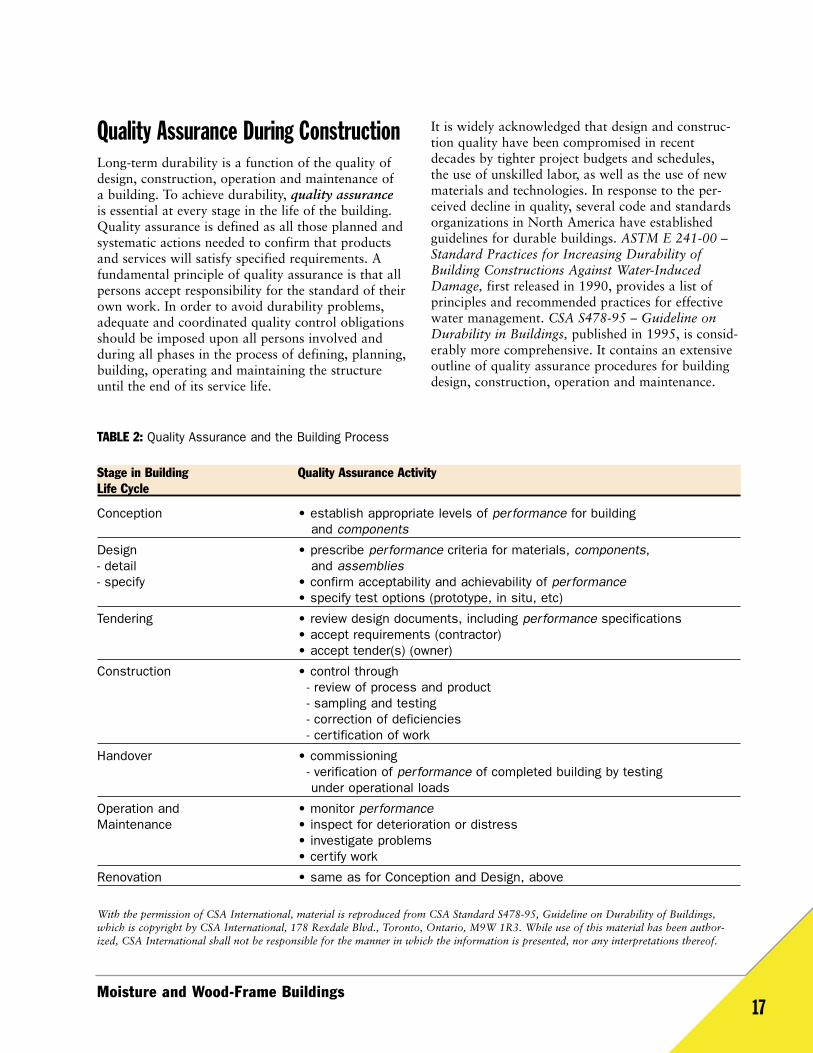
Quality Assurance During ConstructionLong-term durability is a function of the quality ofdesign, construction, operation and maintenance of a building. To achieve durability, quality assuranceis essential at every stage in the life of the building.Quality assurance is defined as all those planned andsystematic actions needed to confirm that productsand services will satisfy specified requirements. Afundamental principle of quality assurance is that allpersons accept responsibility for the standard of theirown work. In order to avoid durability problems,adequate and coordinated quality control obligationsshould be imposed upon all persons involved andduring all phases in the process of defining, planning,building, operating and maintaining the structureuntil the end of its service life.
It is widely acknowledged that design and construc-tion quality have been compromised in recentdecades by tighter project budgets and schedules, the use of unskilled labor, as well as the use of newmaterials and technologies. In response to the per-ceived decline in quality, several code and standardsorganizations in North America have establishedguidelines for durable buildings. ASTM E 241-00 –Standard Practices for Increasing Durability ofBuilding Constructions Against Water-InducedDamage, first released in 1990, provides a list ofprinciples and recommended practices for effectivewater management. CSA S478-95 – Guideline onDurability in Buildings, published in 1995, is consid-erably more comprehensive. It contains an extensiveoutline of quality assurance procedures for buildingdesign, construction, operation and maintenance.
TABLE 2: Quality Assurance and the Building Process
Stage in Building Quality Assurance ActivityLife Cycle
Conception • establish appropriate levels of performance for building and components
Design • prescribe performance criteria for materials, components, - detail and assemblies- specify • confirm acceptability and achievability of performance
• specify test options (prototype, in situ, etc)
Tendering • review design documents, including performance specifications• accept requirements (contractor)• accept tender(s) (owner)
Construction • control through- review of process and product- sampling and testing- correction of deficiencies- certification of work
Handover • commissioning- verification of performance of completed building by testingunder operational loads
Operation and • monitor performanceMaintenance • inspect for deterioration or distress
• investigate problems• certify work
Renovation • same as for Conception and Design, above
With the permission of CSA International, material is reproduced from CSA Standard S478-95, Guideline on Durability of Buildings,which is copyright by CSA International, 178 Rexdale Blvd., Toronto, Ontario, M9W 1R3. While use of this material has been author-ized, CSA International shall not be responsible for the manner in which the information is presented, nor any interpretations thereof.
Construction Quality ControlProper design alone will not ensure the delivery of a durable building to the owner. The constructionprocess must follow through with the design intent.This begins in the design phase with constructiondocumentation. The design of the building envelopeshould be clearly communicated to the entire con-struction team. The various moisture control strategiesshould be communicated, perhaps as a narrativedescription and concept drawing on the cover sheetof the drawings. Critical details, including both typi-cal and non-typical conditions, should be provided to installers. Details should be adequately consideredwith respect to constructability and the overall watermanagement strategy of the wall. Large-scale draw-ings, and in some cases three-dimensional drawings,are needed to visibly indicate the relationships of various components in the assembly. In particular,the drainage plane (moisture barrier and flashings)must be clearly articulated in the detailing. If thedesign intent and assumptions are not clearly articulated, it is quite possible that installers will misinterpret the details during construction.
The builder should develop a rigorous set of proceduresfor quality control during construction. Coordinationof the work is essential to ensure long-term perform-ance, particularly with the building envelope, wheremany different trades must interface. Submittals,shop drawings and pre-installation meetings are alltools that should be used during the constructionphase to clarify, refine and verify the design. Mock-ups are another useful tool, allowing the designerand builder to work with the various trades involvedin the building envelope construction and resolveissues related to constructability and sequencing.Once tested and approved, mock-ups can be used toestablish a visible and tangible standard for the workthat follows.
Material HandlingControl of moisture during construction is also important. Even when dry lumber is purchased and delivered to the jobsite, it can be wetted prior to or during construction. Procedures should be developed to:
• keep wood-based materials dry while in storageonsite,
• minimize wetting of installed materials, and• promote drying of materials with venting, heating
or dehumidification. Wood materials that are exposed to wetting shouldbe dried to 19% moisture content or less prior toenclosure within assemblies. On buildings that areexposed to significant wetting during construction,schedules should provide an allowance for properdrying to framing and sheathing materials. Moisturebarriers, installed soon after assemblies are framed,can be used to minimize exposure to weather.Mechanical measures, such as provision of artificialheat and/or dehumidification, can be utilized tospeed the drying process.
Building Performance Series No. 118
ConclusionWood-frame buildings have an established record oflong-term durability. Wood will continue to be thematerial of choice due to its environmental advan-tages, ease of use and cost competitiveness. With thecorrect application of building envelope design prin-ciples, all materials can perform well with regards todurability.
The imperative for durable construction goes beyondcreating healthy buildings as we must build durablyto minimize the environmental impacts of our society.In fact, wood buildings perform well against othermaterials when considered from a life cycle cost perspective that factors things like greenhouse gasemissions, water pollution index, energy use, solidwaste and ecological resource use. However, theenvironmental advantages of wood can only beachieved if the building is designed and constructedfor long-term durability.
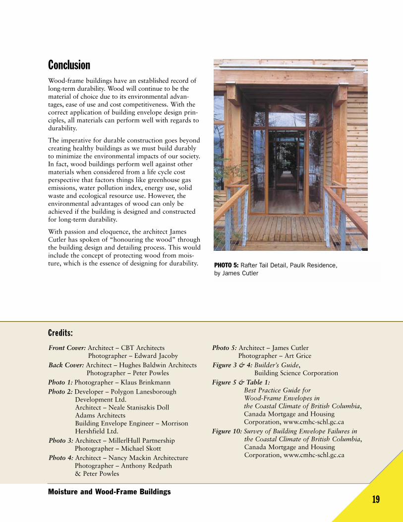
With passion and eloquence, the architect JamesCutler has spoken of “honouring the wood” throughthe building design and detailing process. This wouldinclude the concept of protecting wood from mois-ture, which is the essence of designing for durability.
Moisture and Wood-Frame Buildings19
PHOTO 5: Rafter Tail Detail, Paulk Residence, by James Cutler
Front Cover: Architect – CBT ArchitectsPhotographer – Edward Jacoby
Back Cover: Architect – Hughes Baldwin ArchitectsPhotographer – Peter Powles
Photo 1: Photographer – Klaus BrinkmannPhoto 2: Developer – Polygon Lanesborough
Development Ltd.Architect – Neale Staniszkis Doll Adams ArchitectsBuilding Envelope Engineer – MorrisonHershfield Ltd.
Photo 3: Architect – Miller|Hull PartnershipPhotographer – Michael Skott
Photo 4: Architect – Nancy Mackin ArchitecturePhotographer – Anthony Redpath & Peter Powles
Photo 5: Architect – James CutlerPhotographer – Art Grice
Figure 3 & 4: Builder’s Guide, Building Science Corporation
Figure 5 & Table 1:Best Practice Guide for Wood-Frame Envelopes in the Coastal Climate of British Columbia,Canada Mortgage and HousingCorporation, www.cmhc-schl.gc.ca
Figure 10: Survey of Building Envelope Failures inthe Coastal Climate of British Columbia,Canada Mortgage and HousingCorporation, www.cmhc-schl.gc.ca
Credits:
Canadian Wood Council
1400 Blair Place, Suite 210
Ottawa, ON K1J 9B8
Tel: 1-800-463-5091
Fax: 1-613-747-6264
e-mail: [email protected]
Our Web Sites:
Wood Durability:www.durable-wood.com
Canadian Wood Council:www.cwc.ca
Canada’s Forest Networkwww.cfn.ca
Wood Design & Building Magazine:www.wood.ca
WoodWorks® Design Office Software:www.woodworks-software.com
WoodWORKS! Project:www.wood-works.org
CanadianWoodCouncil
Conseilcanadiendu bois