Section 9.23. Wood-Frame Construction
28
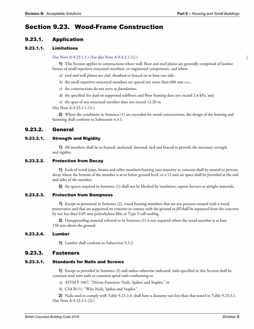
Division B: Acceptable Solutions Part 9 – Housing and Small Buildings British Columbia Building Code 2018 Division B Section 9.23. Wood-Frame Construction 9.23.1. Application 9.23.1.1. Limitations (See Note A-9.23.1.1.) (See also Note A-9.4.2.1.(1).) 1) This Section applies to constructions where wall, floor and roof planes are generally comprised of lumber frames of small repetitive structural members, or engineered components, and where a) roof and wall planes are clad, sheathed or braced on at least one side, b) the small repetitive structural members are spaced not more than 600 mm o.c., c) the constructions do not serve as foundations, d) the specified live load on supported subfloors and floor framing does not exceed 2.4 kPa, and e) the span of any structural member does not exceed 12.20 m. (See Note A-9.23.1.1.(1).) 2) Where the conditions in Sentence (1) are exceeded for wood constructions, the design of the framing and fastening shall conform to Subsection 4.3.1. 9.23.2. General 9.23.2.1. Strength and Rigidity 1) All members shall be so framed, anchored, fastened, tied and braced to provide the necessary strength and rigidity. 9.23.2.2. Protection from Decay 1) Ends of wood joists, beams and other members framing into masonry or concrete shall be treated to prevent decay where the bottom of the member is at or below ground level, or a 12 mm air space shall be provided at the end and sides of the member. 2) Air spaces required in Sentence (1) shall not be blocked by insulation, vapour barriers or airtight materials. 9.23.2.3. Protection from Dampness 1) Except as permitted in Sentence (2), wood framing members that are not pressure-treated with a wood preservative and that are supported on concrete in contact with the ground or fill shall be separated from the concrete by not less than 0.05 mm polyethylene film or Type S roll roofing. 2) Dampproofing material referred to in Sentence (1) is not required where the wood member is at least 150 mm above the ground. 9.23.2.4. Lumber 1) Lumber shall conform to Subsection 9.3.2. 9.23.3. Fasteners 9.23.3.1. Standards for Nails and Screws 1) Except as provided in Sentence (2) and unless otherwise indicated, nails specified in this Section shall be common steel wire nails or common spiral nails conforming to a) ASTM F 1667, “Driven Fasteners: Nails, Spikes, and Staples,” or b) CSA B111, “Wire Nails, Spikes and Staples.” 2) Nails used to comply with Table 9.23.3.4. shall have a diameter not less than that stated in Table 9.23.3.1. (See Note A-9.23.3.1.(2).)
Transcript of Section 9.23. Wood-Frame Construction
Division B: Acceptable Solutions Part 9 – Housing and Small Buildings
British Columbia Building Code 2018 Division B
Section 9.23. Wood-Frame Construction
9.23.1. Application9.23.1.1. Limitations
(See Note A-9.23.1.1.) (See also Note A-9.4.2.1.(1).)
1) This Section applies to constructions where wall, floor and roof planes are generally comprised of lumber frames of small repetitive structural members, or engineered components, and where
a) roof and wall planes are clad, sheathed or braced on at least one side,
b) the small repetitive structural members are spaced not more than 600 mm o.c.,
c) the constructions do not serve as foundations,
d) the specified live load on supported subfloors and floor framing does not exceed 2.4 kPa, and
e) the span of any structural member does not exceed 12.20 m.(See Note A-9.23.1.1.(1).)
2) Where the conditions in Sentence (1) are exceeded for wood constructions, the design of the framing and fastening shall conform to Subsection 4.3.1.
9.23.2. General9.23.2.1. Strength and Rigidity
1) All members shall be so framed, anchored, fastened, tied and braced to provide the necessary strength and rigidity.
9.23.2.2. Protection from Decay
1) Ends of wood joists, beams and other members framing into masonry or concrete shall be treated to prevent decay where the bottom of the member is at or below ground level, or a 12 mm air space shall be provided at the end and sides of the member.
2) Air spaces required in Sentence (1) shall not be blocked by insulation, vapour barriers or airtight materials.
9.23.2.3. Protection from Dampness
1) Except as permitted in Sentence (2), wood framing members that are not pressure-treated with a wood preservative and that are supported on concrete in contact with the ground or fill shall be separated from the concrete by not less than 0.05 mm polyethylene film or Type S roll roofing.
2) Dampproofing material referred to in Sentence (1) is not required where the wood member is at least 150 mm above the ground.
9.23.2.4. Lumber
1) Lumber shall conform to Subsection 9.3.2.
9.23.3. Fasteners9.23.3.1. Standards for Nails and Screws
1) Except as provided in Sentence (2) and unless otherwise indicated, nails specified in this Section shall be common steel wire nails or common spiral nails conforming to
a) ASTM F 1667, “Driven Fasteners: Nails, Spikes, and Staples,” or
b) CSA B111, “Wire Nails, Spikes and Staples.”
2) Nails used to comply with Table 9.23.3.4. shall have a diameter not less than that stated in Table 9.23.3.1. (See Note A-9.23.3.1.(2).)
Part 9 – Housing and Small Buildings Division B: Acceptable Solutions
Division B
3) Wood screws specified in this Section shall conform to ASME B18.6.1, “Wood Screws (Inch Series).” (See Note A-9.23.3.1.(3).)
9.23.3.2. Length of Nails
1) All nails shall be long enough so that not less than half their required length penetrates into the second member.
9.23.3.3. Prevention of Splitting
1) Splitting of wood members shall be minimized by staggering the nails in the direction of the grain and by keeping nails well in from the edges. (See Note A-9.23.3.3.(1).)
9.23.3.4. Nailing of Framing
1) Except as provided in Sentence (2), nailing of framing shall conform to Table 9.23.3.4.
2) Where the bottom wall plate or sole plate of an exterior wall is not nailed to floor joists, rim joists or blocking in conformance with Table 9.23.3.4., the exterior wall is permitted to be fastened to the floor framing by
a) having plywood, OSB or waferboard sheathing extend down over floor framing and fastened to the floor framing by nails or staples conforming to Article 9.23.3.5., or
b) tying the wall framing to the floor framing by galvanized-metal strips
i) 50 mm wide,ii) not less than 0.41 mm thick,
iii) spaced not more than 1.2 m apart, andiv) fastened at each end with at least two 63 mm nails.
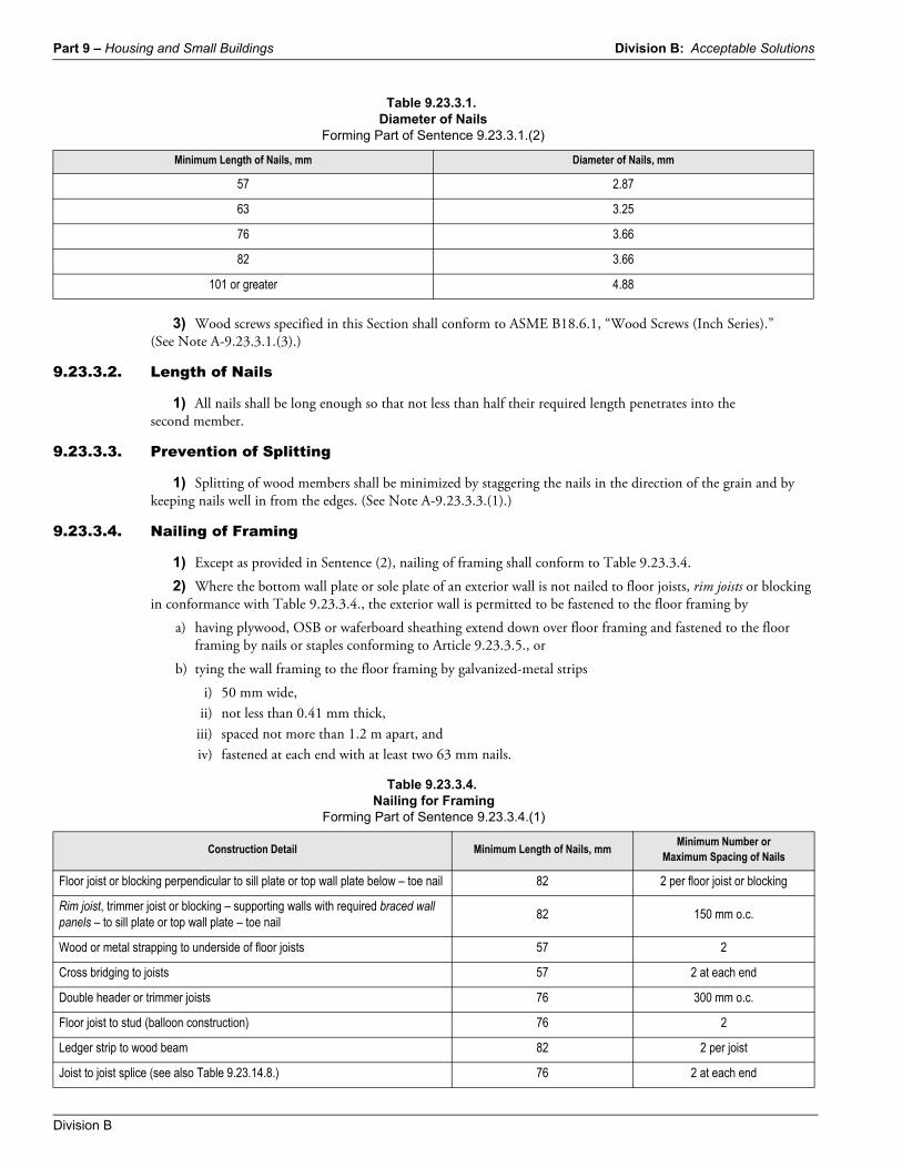
Table 9.23.3.1.Diameter of Nails
Forming Part of Sentence 9.23.3.1.(2)
Minimum Length of Nails, mm Diameter of Nails, mm
57 2.87
63 3.25
76 3.66
82 3.66
101 or greater 4.88
Table 9.23.3.4.Nailing for Framing
Forming Part of Sentence 9.23.3.4.(1)
Construction Detail Minimum Length of Nails, mmMinimum Number or
Maximum Spacing of Nails
Floor joist or blocking perpendicular to sill plate or top wall plate below – toe nail 82 2 per floor joist or blocking
Rim joist, trimmer joist or blocking – supporting walls with required braced wall panels – to sill plate or top wall plate – toe nail
82 150 mm o.c.
Wood or metal strapping to underside of floor joists 57 2
Cross bridging to joists 57 2 at each end
Double header or trimmer joists 76 300 mm o.c.
Floor joist to stud (balloon construction) 76 2
Ledger strip to wood beam 82 2 per joist
Joist to joist splice (see also Table 9.23.14.8.) 76 2 at each end
Division B: Acceptable Solutions Part 9 – Housing and Small Buildings
British Columbia Building Code 2018 Division B
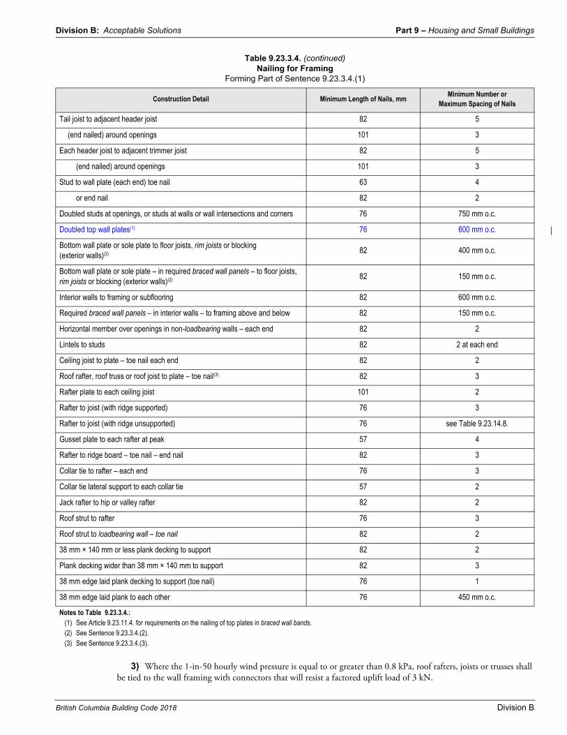
3) Where the 1-in-50 hourly wind pressure is equal to or greater than 0.8 kPa, roof rafters, joists or trusses shall be tied to the wall framing with connectors that will resist a factored uplift load of 3 kN.
Tail joist to adjacent header joist 82 5
(end nailed) around openings 101 3
Each header joist to adjacent trimmer joist 82 5
(end nailed) around openings 101 3
Stud to wall plate (each end) toe nail 63 4
or end nail 82 2
Doubled studs at openings, or studs at walls or wall intersections and corners 76 750 mm o.c.
Doubled top wall plates(1) 76 600 mm o.c.
Bottom wall plate or sole plate to floor joists, rim joists or blocking (exterior walls)(2) 82 400 mm o.c.
Bottom wall plate or sole plate – in required braced wall panels – to floor joists, rim joists or blocking (exterior walls)(2) 82 150 mm o.c.
Interior walls to framing or subflooring 82 600 mm o.c.
Required braced wall panels – in interior walls – to framing above and below 82 150 mm o.c.
Horizontal member over openings in non-loadbearing walls – each end 82 2
Lintels to studs 82 2 at each end
Ceiling joist to plate – toe nail each end 82 2
Roof rafter, roof truss or roof joist to plate – toe nail(3) 82 3
Rafter plate to each ceiling joist 101 2
Rafter to joist (with ridge supported) 76 3
Rafter to joist (with ridge unsupported) 76 see Table 9.23.14.8.
Gusset plate to each rafter at peak 57 4
Rafter to ridge board – toe nail – end nail 82 3
Collar tie to rafter – each end 76 3
Collar tie lateral support to each collar tie 57 2
Jack rafter to hip or valley rafter 82 2
Roof strut to rafter 76 3
Roof strut to loadbearing wall – toe nail 82 2
38 mm × 140 mm or less plank decking to support 82 2
Plank decking wider than 38 mm × 140 mm to support 82 3
38 mm edge laid plank decking to support (toe nail) 76 1
38 mm edge laid plank to each other 76 450 mm o.c.
Notes to Table 9.23.3.4.:(1) See Article 9.23.11.4. for requirements on the nailing of top plates in braced wall bands.(2) See Sentence 9.23.3.4.(2).(3) See Sentence 9.23.3.4.(3).
Table 9.23.3.4. (continued)Nailing for Framing
Forming Part of Sentence 9.23.3.4.(1)
Construction Detail Minimum Length of Nails, mmMinimum Number or
Maximum Spacing of Nails
Part 9 – Housing and Small Buildings Division B: Acceptable Solutions
Division B
4) Galvanized-steel straps are deemed to comply with Sentence (3), provided they are
a) 50 mm wide,
b) not less than 0.91 mm thick, and
c) fastened at each end with at least four 63 mm nails.
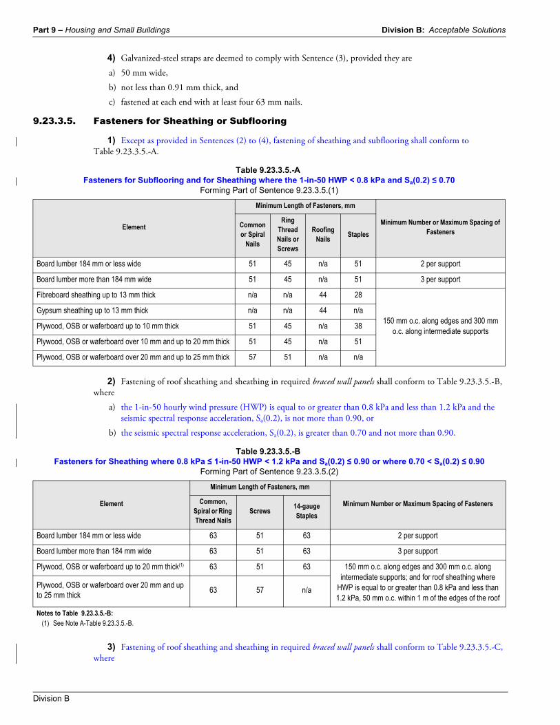
9.23.3.5. Fasteners for Sheathing or Subflooring
1) Except as provided in Sentences (2) to (4), fastening of sheathing and subflooring shall conform to Table 9.23.3.5.-A.
2) Fastening of roof sheathing and sheathing in required braced wall panels shall conform to Table 9.23.3.5.-B, where
a) the 1-in-50 hourly wind pressure (HWP) is equal to or greater than 0.8 kPa and less than 1.2 kPa and the seismic spectral response acceleration, Sa(0.2), is not more than 0.90, or
b) the seismic spectral response acceleration, Sa(0.2), is greater than 0.70 and not more than 0.90.
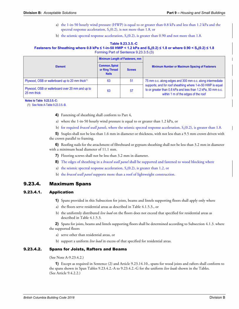
3) Fastening of roof sheathing and sheathing in required braced wall panels shall conform to Table 9.23.3.5.-C, where
Table 9.23.3.5.-AFasteners for Subflooring and for Sheathing where the 1-in-50 HWP < 0.8 kPa and Sa(0.2) ≤ 0.70
Forming Part of Sentence 9.23.3.5.(1)
Element
Minimum Length of Fasteners, mm
Minimum Number or Maximum Spacing of Fasteners
Common or Spiral
Nails
Ring Thread Nails or Screws
Roofing Nails
Staples
Board lumber 184 mm or less wide 51 45 n/a 51 2 per support
Board lumber more than 184 mm wide 51 45 n/a 51 3 per support
Fibreboard sheathing up to 13 mm thick n/a n/a 44 28
150 mm o.c. along edges and 300 mm o.c. along intermediate supports
Gypsum sheathing up to 13 mm thick n/a n/a 44 n/a
Plywood, OSB or waferboard up to 10 mm thick 51 45 n/a 38
Plywood, OSB or waferboard over 10 mm and up to 20 mm thick 51 45 n/a 51
Plywood, OSB or waferboard over 20 mm and up to 25 mm thick 57 51 n/a n/a
Table 9.23.3.5.-BFasteners for Sheathing where 0.8 kPa ≤ 1-in-50 HWP < 1.2 kPa and Sa(0.2) ≤ 0.90 or where 0.70 < Sa(0.2) ≤ 0.90
Forming Part of Sentence 9.23.3.5.(2)
Element
Minimum Length of Fasteners, mm
Minimum Number or Maximum Spacing of FastenersCommon, Spiral or Ring Thread Nails
Screws14-gauge Staples
Board lumber 184 mm or less wide 63 51 63 2 per support
Board lumber more than 184 mm wide 63 51 63 3 per support
Plywood, OSB or waferboard up to 20 mm thick(1) 63 51 63 150 mm o.c. along edges and 300 mm o.c. along intermediate supports; and for roof sheathing where
HWP is equal to or greater than 0.8 kPa and less than 1.2 kPa, 50 mm o.c. within 1 m of the edges of the roof
Plywood, OSB or waferboard over 20 mm and up to 25 mm thick
63 57 n/a
Notes to Table 9.23.3.5.-B:(1) See Note A-Table 9.23.3.5.-B.
Division B: Acceptable Solutions Part 9 – Housing and Small Buildings
British Columbia Building Code 2018 Division B
a) the 1-in-50 hourly wind pressure (HWP) is equal to or greater than 0.8 kPa and less than 1.2 kPa and the spectral response acceleration, Sa(0.2), is not more than 1.8, or
b) the seismic spectral response acceleration, Sa(0.2), is greater than 0.90 and not more than 1.8.
4) Fastening of sheathing shall conform to Part 4,
a) where the 1-in-50 hourly wind pressure is equal to or greater than 1.2 kPa, or
b) for required braced wall panels, where the seismic spectral response acceleration, Sa(0.2), is greater than 1.8.
5) Staples shall not be less than 1.6 mm in diameter or thickness, with not less than a 9.5 mm crown driven with the crown parallel to framing.
6) Roofing nails for the attachment of fibreboard or gypsum sheathing shall not be less than 3.2 mm in diameter with a minimum head diameter of 11.1 mm.
7) Flooring screws shall not be less than 3.2 mm in diameter.
8) The edges of sheathing in a braced wall panel shall be supported and fastened to wood blocking where
a) the seismic spectral response acceleration, Sa(0.2), is greater than 1.2, or
b) the braced wall panel supports more than a roof of lightweight construction.
9.23.4. Maximum Spans9.23.4.1. Application
1) Spans provided in this Subsection for joists, beams and lintels supporting floors shall apply only where
a) the floors serve residential areas as described in Table 4.1.5.3., or
b) the uniformly distributed live load on the floors does not exceed that specified for residential areas as described in Table 4.1.5.3.
2) Spans for joists, beams and lintels supporting floors shall be determined according to Subsection 4.1.3. where the supported floors
a) serve other than residential areas, or
b) support a uniform live load in excess of that specified for residential areas.
9.23.4.2. Spans for Joists, Rafters and Beams
(See Note A-9.23.4.2.)
1) Except as required in Sentence (2) and Article 9.23.14.10., spans for wood joists and rafters shall conform to the spans shown in Span Tables 9.23.4.2.-A to 9.23.4.2.-G for the uniform live loads shown in the Tables. (See Article 9.4.2.2.)
Table 9.23.3.5.-CFasteners for Sheathing where 0.8 kPa ≤ 1-in-50 HWP < 1.2 kPa and Sa(0.2) ≤ 1.8 or where 0.90 < Sa(0.2) ≤ 1.8
Forming Part of Sentence 9.23.3.5.(3)
Element
Minimum Length of Fasteners, mm
Minimum Number or Maximum Spacing of FastenersCommon, Spiral or Ring Thread
NailsScrews
Plywood, OSB or waferboard up to 20 mm thick(1) 63 51 75 mm o.c. along edges and 300 mm o.c. along intermediate supports; and for roof sheathing where 1-in-50 HWP is equal to or greater than 0.8 kPa and less than 1.2 kPa, 50 mm o.c.
within 1 m of the edges of the roof
Plywood, OSB or waferboard over 20 mm and up to 25 mm thick
63 57
Notes to Table 9.23.3.5.-C:(1) See Note A-Table 9.23.3.5.-B.
Part 9 – Housing and Small Buildings Division B: Acceptable Solutions
Division B
2) Spans for floor joists that are not selected from Span Tables 9.23.4.2.-A and 9.23.4.2.-B and that are required to be designed for the same loading conditions, shall not exceed the design requirements for uniform loading and vibration criteria. (See Note A-9.23.4.2.(2).)
3) Spans for built-up wood and glued-laminated timber floor beams shall conform to the spans in Span Tables 9.23.4.2.-H to 9.23.4.2.-K. (See Article 9.4.2.2.)
4) Spans for roof ridge beams shall conform to the spans in Span Table 9.23.4.2.-L for the uniform snow load shown. (See Articles 9.4.2.2. and 9.23.14.8.)
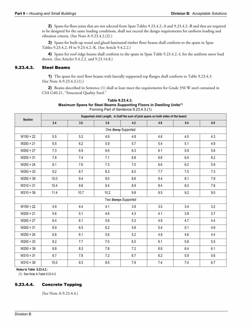
9.23.4.3. Steel Beams
1) The spans for steel floor beams with laterally supported top flanges shall conform to Table 9.23.4.3. (See Note A-9.23.4.3.(1).)
2) Beams described in Sentence (1) shall at least meet the requirements for Grade 350 W steel contained in CSA G40.21, “Structural Quality Steel.”
9.23.4.4. Concrete Topping
(See Note A-9.23.4.4.)
Table 9.23.4.3.Maximum Spans for Steel Beams Supporting Floors in Dwelling Units(1)
Forming Part of Sentence 9.23.4.3.(1)
Section Supported Joist Length, m (half the sum of joist spans on both sides of the beam)
2.4 3.0 3.6 4.2 4.8 5.4 6.0
One Storey Supported
W150 × 22 5.5 5.2 4.9 4.8 4.6 4.5 4.3
W200 × 21 6.5 6.2 5.9 5.7 5.4 5.1 4.9
W200 × 27 7.3 6.9 6.6 6.3 6.1 5.9 5.8
W200 × 31 7.8 7.4 7.1 6.8 6.6 6.4 6.2
W250 × 24 8.1 7.6 7.3 7.0 6.6 6.2 5.9
W250 × 33 9.2 8.7 8.3 8.0 7.7 7.5 7.3
W250 × 39 10.0 9.4 9.0 8.6 8.4 8.1 7.9
W310 × 31 10.4 9.8 9.4 8.9 8.4 8.0 7.6
W310 × 39 11.4 10.7 10.2 9.8 9.5 9.2 9.0
Two Storeys Supported
W150 × 22 4.9 4.4 4.1 3.8 3.5 3.4 3.2
W200 × 21 5.6 5.1 4.6 4.3 4.1 3.8 3.7
W200 × 27 6.4 6.1 5.6 5.3 4.9 4.7 4.4
W200 × 31 6.9 6.5 6.2 5.8 5.4 5.1 4.9
W250 × 24 6.8 6.1 5.6 5.2 4.9 4.6 4.4
W250 × 33 8.2 7.7 7.0 6.5 6.1 5.8 5.5
W250 × 39 8.8 8.3 7.8 7.2 6.8 6.4 6.1
W310 × 31 8.7 7.8 7.2 6.7 6.2 5.9 5.6
W310 × 39 10.0 9.3 8.5 7.9 7.4 7.0 6.7
Notes to Table 9.23.4.3.:(1) See Note A-Table 9.23.4.3.
Division B: Acceptable Solutions Part 9 – Housing and Small Buildings
British Columbia Building Code 2018 Division B
1) Except as permitted in Sentence (2), where a floor is required to support a concrete topping, the joist spans shown in Span Table 9.23.4.2.-A or the spacing of the members shall be reduced to allow for the loads due to the topping.
2) Where a floor is required to support a concrete topping, joist spans are permitted to be selected from Span Table 9.23.4.2.-B provided the concrete
a) is 38 to 51 mm thick,
b) is normal weight,
c) is placed directly on the subflooring, and
d) has not less than 20 MPa compressive strength after 28 days.
3) Where a floor is required to support a concrete topping not more than 51 mm thick, the allowable beam spans shown in Span Tables 9.23.4.2.-H to 9.23.4.2.-K shall be multiplied by 0.8 or the supported length of the floor joists shall be reduced to allow for the loads due to the topping.
9.23.4.5. Heavy Roofing Materials
1) Where a roof is required to support an additional uniform dead load from roofing materials such as concrete roofing tile, or materials other than as specified in Section 9.27., such as clay roofing tiles, the additional load shall be allowed for by reducing
a) the spans for roof joists and rafters in Span Tables 9.23.4.2.-D to 9.23.4.2.-G, or the spacing of the members, and
b) the spans for ridge beams and lintels in Span Tables 9.23.4.2.-L and 9.23.12.3.-A to 9.23.12.3.-D.(See Note A-9.23.4.2.)
9.23.5. Notching and Drilling9.23.5.1. Holes Drilled in Framing Members
1) Holes drilled in roof, floor or ceiling framing members shall be not larger than one-quarter the depth of the member and shall be located not less than 50 mm from the edges, unless the depth of the member is increased by the size of the hole.
9.23.5.2. Notching of Framing Members
1) Floor, roof and ceiling framing members are permitted to be notched provided the notch is located on the top of the member within half the joist depth from the edge of bearing and is not deeper than one-third the joist depth, unless the depth of the member is increased by the size of the notch.
9.23.5.3. Wall Studs
1) Wall studs shall not be notched, drilled or otherwise damaged so that the undamaged portion of the stud is less than two-thirds the depth of the stud if the stud is loadbearing or 40 mm if the stud is non-loadbearing, unless the weakened studs are suitably reinforced.
9.23.5.4. Top Plates
1) Top plates in walls shall not be notched, drilled or otherwise weakened to reduce the undamaged width to less than 50 mm unless the weakened plates are suitably reinforced.
9.23.5.5. Roof Trusses
1) Roof truss members shall not be notched, drilled or otherwise weakened unless such notching or drilling is allowed for in the design of the truss.
Part 9 – Housing and Small Buildings Division B: Acceptable Solutions
Division B
9.23.6. Anchorage9.23.6.1. Anchorage of Building Frames
1) Except as required by Sentence 9.23.6.3.(1), building frames shall be anchored to the foundation unless a structural analysis of wind and earthquake pressures shows anchorage is not required.
2) Except as provided in Sentences (3) to (6), anchorage shall be provided by
a) embedding the ends of the first floor joists in concrete, or
b) fastening the sill plate to the foundation with not less than 12.7 mm diam anchor bolts spaced not more than 2.4 m o.c.
3) For buildings with 2 or more floors supported by frame walls that are in areas where the seismic spectral response acceleration, Sa(0.2), is not greater than 0.70 or the 1-in-50 hourly wind pressure (HWP) is equal to or greater than 0.80 kPa but not greater than 1.20 kPa, anchorage shall be provided by fastening the sill plate to the foundation with not less than two anchor bolts per braced wall panel, where all anchor bolts used are
a) not less than 15.9 mm in diameter, located within 0.5 m of the end of the foundation, and spaced not more than 2.4 m o.c, or
b) not less than 12.7 mm in diameter, located within 0.5 m of the end of the foundation, and spaced not more than 1.7 m o.c.
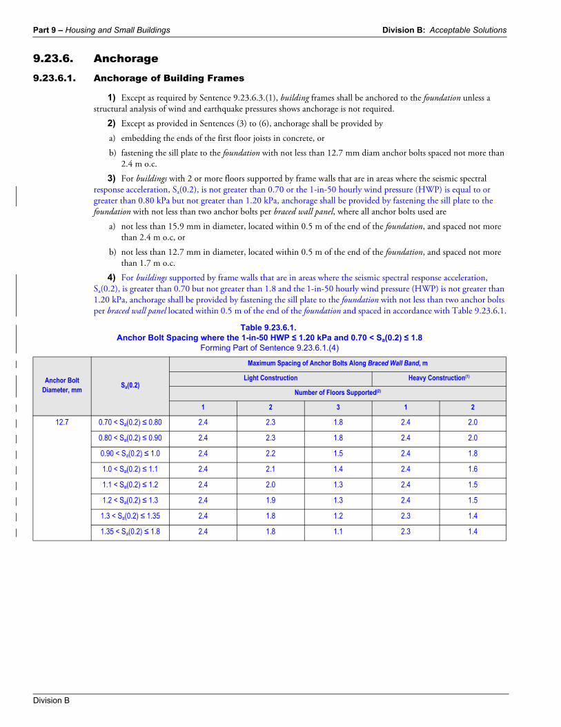
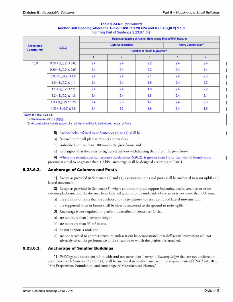
4) For buildings supported by frame walls that are in areas where the seismic spectral response acceleration, Sa(0.2), is greater than 0.70 but not greater than 1.8 and the 1-in-50 hourly wind pressure (HWP) is not greater than 1.20 kPa, anchorage shall be provided by fastening the sill plate to the foundation with not less than two anchor bolts per braced wall panel located within 0.5 m of the end of the foundation and spaced in accordance with Table 9.23.6.1.
Table 9.23.6.1.Anchor Bolt Spacing where the 1-in-50 HWP ≤ 1.20 kPa and 0.70 < Sa(0.2) ≤ 1.8
Forming Part of Sentence 9.23.6.1.(4)
Anchor Bolt Diameter, mm
Sa(0.2)
Maximum Spacing of Anchor Bolts Along Braced Wall Band, m
Light Construction Heavy Construction(1)
Number of Floors Supported(2)
1 2 3 1 2
12.7 0.70 < Sa(0.2) ≤ 0.80 2.4 2.3 1.8 2.4 2.0
0.80 < Sa(0.2) ≤ 0.90 2.4 2.3 1.8 2.4 2.0
0.90 < Sa(0.2) ≤ 1.0 2.4 2.2 1.5 2.4 1.8
1.0 < Sa(0.2) ≤ 1.1 2.4 2.1 1.4 2.4 1.6
1.1 < Sa(0.2) ≤ 1.2 2.4 2.0 1.3 2.4 1.5
1.2 < Sa(0.2) ≤ 1.3 2.4 1.9 1.3 2.4 1.5
1.3 < Sa(0.2) ≤ 1.35 2.4 1.8 1.2 2.3 1.4
1.35 < Sa(0.2) ≤ 1.8 2.4 1.8 1.1 2.3 1.4
Division B: Acceptable Solutions Part 9 – Housing and Small Buildings
British Columbia Building Code 2018 Division B
5) Anchor bolts referred to in Sentences (2) to (4) shall be
a) fastened to the sill plate with nuts and washers,
b) embedded not less than 100 mm in the foundation, and
c) so designed that they may be tightened without withdrawing them from the foundation.
6) Where the seismic spectral response acceleration, Sa(0.2), is greater than 1.8 or the 1-in-50 hourly wind pressure is equal to or greater than 1.2 kPa, anchorage shall be designed according to Part 4.
9.23.6.2. Anchorage of Columns and Posts
1) Except as provided in Sentences (2) and (3), exterior columns and posts shall be anchored to resist uplift and lateral movement.
2) Except as provided in Sentence (3), where columns or posts support balconies, decks, verandas or other exterior platforms, and the distance from finished ground to the underside of the joists is not more than 600 mm,
a) the columns or posts shall be anchored to the foundation to resist uplift and lateral movement, or
b) the supported joists or beams shall be directly anchored to the ground to resist uplift.
3) Anchorage is not required for platforms described in Sentence (2) that
a) are not more than 1 storey in height,
b) are not more than 55 m2 in area,
c) do not support a roof, and
d) are not attached to another structure, unless it can be demonstrated that differential movement will not adversely affect the performance of the structure to which the platform is attached.
9.23.6.3. Anchorage of Smaller Buildings
1) Buildings not more than 4.3 m wide and not more than 1 storey in building height that are not anchored in accordance with Sentence 9.23.6.1.(1) shall be anchored in conformance with the requirements of CSA Z240.10.1, “Site Preparation, Foundation, and Anchorage of Manufactured Homes.”
15.9 0.70 < Sa(0.2) ≤ 0.80 2.4 2.4 2.2 2.4 2.4
0.80 < Sa(0.2) ≤ 0.90 2.4 2.4 2.2 2.4 2.4
0.90 < Sa(0.2) ≤ 1.0 2.4 2.4 2.1 2.4 2.3
1.0 < Sa(0.2) ≤ 1.1 2.4 2.4 1.9 2.4 2.3
1.1 < Sa(0.2) ≤ 1.2 2.4 2.4 1.9 2.4 2.2
1.2 < Sa(0.2) ≤ 1.3 2.4 2.4 1.8 2.4 2.1
1.3 < Sa(0.2) ≤ 1.35 2.4 2.3 1.7 2.4 2.0
1.35 < Sa(0.2) ≤ 1.8 2.4 2.2 1.6 2.4 1.9
Notes to Table 9.23.6.1.:(1) See Note A-9.23.13.2.(1)(a)(i).(2) All constructions include support of a roof load in addition to the indicated number of floors.
Table 9.23.6.1. (continued)Anchor Bolt Spacing where the 1-in-50 HWP ≤ 1.20 kPa and 0.70 < Sa(0.2) ≤ 1.8
Forming Part of Sentence 9.23.6.1.(4)
Anchor Bolt Diameter, mm
Sa(0.2)
Maximum Spacing of Anchor Bolts Along Braced Wall Band, m
Light Construction Heavy Construction(1)
Number of Floors Supported(2)
1 2 3 1 2
Part 9 – Housing and Small Buildings Division B: Acceptable Solutions
Division B
9.23.7. Sill Plates9.23.7.1. Size of Sill Plates
1) Where sill plates provide bearing for the floor system, they shall be not less than 38 mm by 89 mm material.
9.23.7.2. Levelling and Sealing of Sill Plates
1) Sill plates shall be
a) levelled by setting them on a full bed of mortar, or
b) laid directly on the foundation if the top of the foundation is level.(See also Article 9.23.2.3.)
2) The joint between the sill plate for exterior walls and the foundation shall be sealed in accordance with Subsection 9.25.3.
9.23.8. Beams to Support Floors9.23.8.1. Bearing for Beams
1) Beams shall have even and level bearing and the bearing at end supports shall be not less than 89 mm long, except as stated in the notes to Span Tables 9.23.4.2.-H to 9.23.4.2.-K.
9.23.8.2. Priming of Steel Beams
1) Exterior steel beams shall be shop primed.
9.23.8.3. Built-up Wood Beams
(See Note A-9.23.8.3.)
1) Where a beam is made up of individual pieces of lumber that are nailed together, the individual members shall be 38 mm or greater in thickness and installed on edge.
2) Except as permitted in Sentence (3), where individual members of a built-up beam are butted together to form a joint, the joint shall occur over a support.
3) Where a beam is continuous over more than one span, individual members are permitted to be butted together to form a joint at or within 150 mm of the end quarter points of the clear spans, provided the quarter points are not those closest to the ends of the beam.
4) Members joined at quarter points shall be continuous over adjacent supports.
5) Joints in individual members of a beam that are located at or near the end quarter points shall not occur in adjacent members at the same quarter point and shall not reduce the effective beam width by more than half.
6) Not more than one butt joint shall occur in any individual member of a built-up beam within any one span.
7) Except as provided in Sentence (8), where 38 mm members are laid on edge to form a built-up beam, individual members shall be nailed together with a double row of nails not less than 89 mm in length, spaced not more than 450 mm apart in each row with the end nails located 100 mm to 150 mm from the end of each piece.
8) Where 38 mm members in built-up wood beams are not nailed together as provided in Sentence (7), they shall be bolted together with not less than 12.7 mm diam bolts equipped with washers and spaced not more than 1.2 m o.c., with the end bolts located not more than 600 mm from the ends of the members.
9.23.9. Floor Joists9.23.9.1. End Bearing for Joists
1) Except when supported on ribbon boards, floor joists shall have not less than 38 mm length of end bearing.
2) Ribbon boards referred to in Sentence (1) shall be not less than 19 mm by 89 mm lumber let into the studs.
Division B: Acceptable Solutions Part 9 – Housing and Small Buildings
British Columbia Building Code 2018 Division B
9.23.9.2. Joists Supported by Beams
1) Floor joists may be supported on the tops of beams or may be framed into the sides of beams.
2) When framed into the side of a wood beam, joists referred to in Sentence (1) shall be supported on
a) joist hangers or other acceptable mechanical connectors, or
b) not less than 38 mm by 64 mm ledger strips nailed to the side of the beam, except that 38 mm by 38 mm ledger strips may be used provided each joist is nailed to the beam by not less than four 89 mm nails, in addition to the nailing for the ledger strip required in Table 9.23.3.4.
3) When framed into the side of a steel beam, joists referred to in Sentence (1) shall be supported on the bottom flange of the beam or on not less than 38 mm by 38 mm lumber bolted to the web with not less than 6.3 mm diam bolts spaced not more than 600 mm apart.
4) Joists referred to in Sentence (3) shall be spliced above the beam with not less than 38 mm by 38 mm lumber at least 600 mm long to support the flooring.
5) Not less than a 12 mm space shall be provided between the splice required in Sentence (4) and the beam to allow for shrinkage of the wood joists.
9.23.9.3. Restraint of Joist Bottoms
1) Except as provided in Sentence 9.23.9.4.(1), bottoms of floor joists shall be restrained from twisting at each end by toe-nailing to the supports, end-nailing to the header joists or by providing continuous strapping, blocking between the joists or cross-bridging near the supports.
9.23.9.4. Strapping, Bridging, Furring and Ceilings in Span Tables 9.23.4.2.-A and -B
(See Note A-9.23.4.2.(2).)
1) Except as permitted by Sentence (5), where strapping is specified in Span Table 9.23.4.2.-A, it shall be
a) not less than 19 mm by 64 mm, nailed to the underside of floor joists,
b) located not more than 2 100 mm from each support or other rows of strapping, and
c) fastened at each end to a sill or header.
2) Where bridging is specified in Span Table 9.23.4.2.-A, it shall consist of not less than 19 mm by 64 mm or 38 mm by 38 mm cross bridging located not more than 2 100 mm from each support or other rows of bridging.
3) Where bridging and strapping are specified in Span Table 9.23.4.2.-A,
a) bridging shall
i) comply with Sentence (2), orii) consist of 38 mm solid blocking located not more than 2 100 mm from each support or other rows of
bridging and securely fastened between the joists, and
b) except as provided in Sentence (5), strapping shall comply with Sentence (1) and be installed under the bridging.
4) Bridging specified in Span Table 9.23.4.2.-B shall consist of
a) bridging as described in Sentence (2), or
b) 38 mm solid blocking located not more than 2 100 mm from each support or other rows of bridging and securely fastened between the joists.
5) Strapping described in Sentence (1) and Clause (3)(b) is not required where
a) furring strips complying with Table 9.29.3.1. are fastened directly to the joists, or
b) a panel-type ceiling finish complying with Subsection 9.29.5., 9.29.6., 9.29.7., 9.29.8., or 9.29.9. is attached directly to the joists.
6) Where a ceiling attached to wood furring is specified in Span Table 9.23.4.2.-B,
a) the ceiling finish shall consist of gypsum board, plywood or OSB not less than 12.7 mm thick, and
b) the furring shall be
Part 9 – Housing and Small Buildings Division B: Acceptable Solutions
Division B
i) 19 mm by 89 mm wood furring spaced at not more than 600 mm o.c., orii) 19 mm by 64 mm wood furring spaced at not more than 400 mm o.c.
9.23.9.5. Header Joists
1) Header joists around floor openings shall be doubled when they exceed 1.2 m in length.
2) The size of header joists exceeding 3.2 m in length shall be determined by calculations.
9.23.9.6. Trimmer Joists
1) Trimmer joists around floor openings shall be doubled when the length of the header joist exceeds 800 mm.
2) When the header joist exceeds 2 m in length the size of the trimmer joists shall be determined by calculations.
9.23.9.7. Support of Tail and Header Joists
1) When tail joists and header joists are supported by the floor framing, they shall be supported by suitable joist hangers or nailing in accordance with Table 9.23.3.4.
9.23.9.8. Support of Walls
1) Non-loadbearing walls parallel to the floor joists shall be supported by joists beneath the wall or on blocking between the joists.
2) Blocking referred to in Sentence (1) for the support of non-loadbearing walls shall be
a) not less than 38 mm by 89 mm lumber, and
b) except as required for the fastening of walls constructed with required braced wall panels, spaced not more than 1.2 m apart.
3) Except as provided in Sentence (6), non-loadbearing interior walls at right angles to the floor joists are not restricted as to location.
4) Loadbearing interior walls parallel to floor joists shall be supported by beams or walls of sufficient strength to safely transfer the specified live loads to the vertical supports.
5) Unless the joist size is designed to support such loads, loadbearing interior walls at right angles to floor joists shall be located
a) not more than 900 mm from the joist support where the wall does not support a floor, and
b) not more than 600 mm from the joist support where the wall supports one or more floors.
6) Loadbearing and non-loadbearing walls constructed with required braced wall panels shall be continuously supported by floor joists, blocking or rim joists to allow for the required fastening (see Table 9.23.3.4.).
9.23.9.9. Cantilevered Floor Joists
1) Floor joists supporting roof loads shall not be cantilevered more than 400 mm beyond their supports where 38 mm by 184 mm joists are used and not more than 600 mm beyond their supports where 38 mm by 235 mm or larger joists are used.
2) The cantilevered portions referred to in Sentence (1) shall not support floor loads from other storeys unless calculations are provided to show that the design resistances of the cantilevered joists are not exceeded.
3) Where cantilevered floor joists described in Sentences (1) and (2) are at right angles to the main floor joists, the tail joists in the cantilevered portion shall extend inward away from the cantilever support a distance equal to not less than 6 times the length of the cantilever, and shall be end nailed to an interior doubled header joist in conformance with Table 9.23.3.4.
9.23.10. Wall Studs9.23.10.1. Stud Size and Spacing
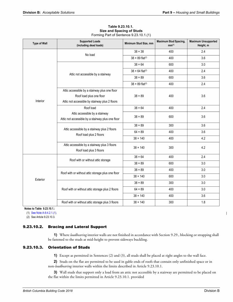
1) The size and spacing of studs shall conform to Table 9.23.10.1.
Division B: Acceptable Solutions Part 9 – Housing and Small Buildings
British Columbia Building Code 2018 Division B
9.23.10.2. Bracing and Lateral Support
1) Where loadbearing interior walls are not finished in accordance with Section 9.29., blocking or strapping shall be fastened to the studs at mid-height to prevent sideways buckling.
9.23.10.3. Orientation of Studs
1) Except as permitted in Sentences (2) and (3), all studs shall be placed at right angles to the wall face.
2) Studs on the flat are permitted to be used in gable ends of roofs that contain only unfinished space or in non-loadbearing interior walls within the limits described in Article 9.23.10.1.
3) Wall studs that support only a load from an attic not accessible by a stairway are permitted to be placed on the flat within the limits permitted in Article 9.23.10.1. provided
Table 9.23.10.1.Size and Spacing of Studs
Forming Part of Sentence 9.23.10.1.(1)
Type of WallSupported Loads
(including dead loads)Minimum Stud Size, mm
Maximum Stud Spacing, mm(1)
Maximum Unsupported Height, m
Interior
No load38 × 38 400 2.4
38 × 89 flat(2) 400 3.6
Attic not accessible by a stairway
38 × 64 600 3.0
38 × 64 flat(2) 400 2.4
38 × 89 600 3.6
38 × 89 flat(2) 400 2.4
Attic accessible by a stairway plus one floor
Roof load plus one floor
Attic not accessible by stairway plus 2 floors
38 × 89 400 3.6
Roof load
Attic accessible by a stairway
Attic not accessible by a stairway plus one floor
38 × 64 400 2.4
38 × 89 600 3.6
Attic accessible by a stairway plus 2 floors
Roof load plus 2 floors
38 × 89 300 3.6
64 × 89 400 3.6
38 × 140 400 4.2
Attic accessible by a stairway plus 3 floors
Roof load plus 3 floors38 × 140 300 4.2
Exterior
Roof with or without attic storage38 × 64 400 2.4
38 × 89 600 3.0
Roof with or without attic storage plus one floor38 × 89 400 3.0
38 × 140 600 3.0
Roof with or without attic storage plus 2 floors
38 × 89 300 3.0
64 × 89 400 3.0
38 × 140 400 3.6
Roof with or without attic storage plus 3 floors 38 × 140 300 1.8
Notes to Table 9.23.10.1.:(1) See Note A-9.4.2.1.(1).(2) See Article 9.23.10.3.
Part 9 – Housing and Small Buildings Division B: Acceptable Solutions
Division B
a) the studs are clad on not less than one side with plywood, OSB or waferboard sheathing fastened to the face of the studs with a structural adhesive, and
b) the portion of the roof supported by the studs does not exceed 2.1 m in width.
9.23.10.4. Continuity of Studs
1) Wall studs shall be continuous for the full storey height except at openings and shall not be spliced except by fingerjoining with a structural adhesive. (See Note A-9.23.10.4.(1).)
9.23.10.5. Support for Cladding, Sheathing and Finishing Materials
1) Corners and intersections shall be designed to provide adequate support for the vertical edges of interior finishes, sheathing and cladding materials, and in no instance shall exterior corners be framed with less than the equivalent of 2 studs.
2) Where the vertical edges of interior finishes at wall intersections are supported at vertical intervals by blocking or furring, the vertical distance between such supports shall not exceed the maximum distance between supports specified in Section 9.29.
9.23.10.6. Studs at Sides of Openings
1) Where the lintel spanning the opening is more than 3 m long, studs shall be tripled on each side of the opening so that
a) the two inner studs on each side extend from the bottom of the supported lintel to the top of the bottom wall plate, and
b) the outer stud on each side extends from the bottom of the top wall plate to the bottom wall plate.
2) Except as provided in Sentence (3), where the lintel spanning the opening is not more than 3 m long, studs shall be doubled on each side of the opening so that
a) the inner studs on each side extend from the bottom of the supported lintel to the top of the bottom wall plate, and
b) the outer stud on each side extends from the bottom of the top wall plate to the bottom wall plate.
3) Single studs are permitted to be used on either side of openings
a) in non-loadbearing interior walls not required to have fire-resistance ratings, provided the studs extend from the top wall plate to the bottom wall plate, or
b) in loadbearing or non-loadbearing interior or exterior walls, provided
i) the opening is less than and within the required stud spacing, andii) no 2 such openings of full stud-space width are located in adjacent stud spaces.
(See Note A-9.23.10.6.(3).)
9.23.11. Wall Plates9.23.11.1. Size of Wall Plates
1) Except as provided in Sentence (2), wall plates shall be
a) not less than 38 mm thick, and
b) not less than the required width of the wall studs.
2) In non-loadbearing walls and in loadbearing walls where the studs are located directly over framing members, the bottom wall plate is permitted to be 19 mm thick.
9.23.11.2. Bottom Wall Plates
1) A bottom wall plate shall be provided in all cases.
2) The bottom plate in exterior walls shall not project more than one-third the plate width over the support.
Division B: Acceptable Solutions Part 9 – Housing and Small Buildings
British Columbia Building Code 2018 Division B
9.23.11.3. Top Plates
1) Except as permitted in Sentences (2) to (4), at least 2 top plates shall be provided in loadbearing walls.
2) A single top plate is permitted to be used in a section of a loadbearing wall containing a lintel provided the top plate forms a tie across the lintel.
3) A single top plate is permitted to be used in loadbearing walls where the concentrated loads from ceilings, floors and roofs are not more than 50 mm to one side of the supporting studs and in all non-loadbearing walls.
4) The top plates need not be provided in a section of loadbearing wall containing a lintel provided the lintel is tied to the adjacent wall section with not less than
a) 75 mm by 150 mm by 0.91 mm thick galvanized steel, or
b) 19 mm by 89 mm by 300 mm wood splice nailed to each wall section with at least three 63 mm nails.
9.23.11.4. Joints in Top Plates
1) Joints in the top plates of loadbearing walls shall be staggered not less than one stud spacing.
2) The top plates in loadbearing walls shall be lapped or otherwise tied at corners and intersecting walls in accordance with Sentence (4).
3) Joints in single top plates used with loadbearing walls shall be tied in accordance with Sentence (4).
4) Ties referred to in Sentences (2) and (3) shall be the equivalent of not less than 75 mm by 150 mm by 0.91 mm thick galvanized steel nailed to each wall with at least three 63 mm nails.
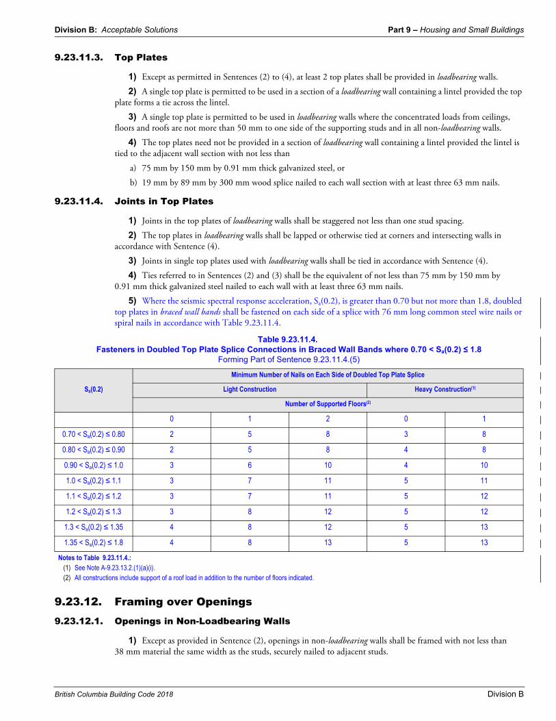
5) Where the seismic spectral response acceleration, Sa(0.2), is greater than 0.70 but not more than 1.8, doubled top plates in braced wall bands shall be fastened on each side of a splice with 76 mm long common steel wire nails or spiral nails in accordance with Table 9.23.11.4.
9.23.12. Framing over Openings9.23.12.1. Openings in Non-Loadbearing Walls
1) Except as provided in Sentence (2), openings in non-loadbearing walls shall be framed with not less than 38 mm material the same width as the studs, securely nailed to adjacent studs.
Table 9.23.11.4.Fasteners in Doubled Top Plate Splice Connections in Braced Wall Bands where 0.70 < Sa(0.2) ≤ 1.8
Forming Part of Sentence 9.23.11.4.(5)
Sa(0.2)
Minimum Number of Nails on Each Side of Doubled Top Plate Splice
Light Construction Heavy Construction(1)
Number of Supported Floors(2)
0 1 2 0 1
0.70 < Sa(0.2) ≤ 0.80 2 5 8 3 8
0.80 < Sa(0.2) ≤ 0.90 2 5 8 4 8
0.90 < Sa(0.2) ≤ 1.0 3 6 10 4 10
1.0 < Sa(0.2) ≤ 1.1 3 7 11 5 11
1.1 < Sa(0.2) ≤ 1.2 3 7 11 5 12
1.2 < Sa(0.2) ≤ 1.3 3 8 12 5 12
1.3 < Sa(0.2) ≤ 1.35 4 8 12 5 13
1.35 < Sa(0.2) ≤ 1.8 4 8 13 5 13
Notes to Table 9.23.11.4.:(1) See Note A-9.23.13.2.(1)(a)(i).(2) All constructions include support of a roof load in addition to the number of floors indicated.
Part 9 – Housing and Small Buildings Division B: Acceptable Solutions
Division B
2) Openings for doors in non-loadbearing walls required to be fire separations with a fire-resistance rating shall be framed with the equivalent of at least two 38 mm thick members that are the same width as the wall plates.
9.23.12.2. Openings in Loadbearing Walls
1) Openings in loadbearing walls greater than the required stud spacing shall be framed with lintels designed to carry the superimposed loads to adjacent studs. (See Note A-9.23.10.6.(3).)
2) Except as provided in Sentence 9.23.12.3.(2), where 2 or more members are used in lintels, they shall be fastened together with not less than 82 mm nails in a double row, with nails not more than 450 mm apart in each row.
3) Lintel members are permitted to be separated by filler pieces.
9.23.12.3. Lintel Spans and Sizes
1) Spans and sizes of wood lintels shall conform to the spans shown in Span Tables 9.23.4.2.-L and 9.23.12.3.-A to 9.23.12.3.-D
a) for buildings of residential occupancy,
b) where the wall studs exceed 38 mm by 64 mm in size,
c) where the spans of supported joists do not exceed 4.9 m, and
d) where the spans of trusses do not exceed 9.8 m.
2) In loadbearing exterior and interior walls of 38 mm by 64 mm framing members, lintels shall consist of
a) 64 mm thick members on edge, or
b) 38 mm thick and 19 mm thick members fastened together with a double row of nails not less than 63 mm long and spaced not more than 450 mm apart.
3) Lintels referred to in Sentence (2)
a) shall be not less than 50 mm greater in depth than those shown in Span Tables 9.23.4.2.-L and 9.23.12.3.-A to 9.23.12.3.-D for the maximum spans shown, and
b) shall not exceed 2.24 m in length.
9.23.13. Bracing to Resist Lateral Loads Due to Wind and Earthquake(See Note A-9.23.13.)
9.23.13.1. Requirements for Low to Moderate Wind and Seismic Forces
(See Note A-9.23.13.1.)
1) This Article applies in locations where the seismic spectral response acceleration, Sa(0.2), is not more than 0.70 and the 1-in-50 hourly wind pressure is less than 0.80 kPa.
2) Bracing to resist lateral loads shall be designed and constructed as follows:
a) exterior walls shall be
i) clad with panel-type cladding in accordance with Section 9.27.,ii) sheathed with plywood, OSB, waferboard, fibreboard, gypsum board or diagonal lumber sheathing
complying with Subsection 9.23.17. and fastened in accordance with Table 9.23.3.5.-A, oriii) finished on the interior with a panel-type material in accordance with the requirements of
Section 9.29., or
b) in accordance with
i) Articles 9.23.13.4. to 9.23.13.7.,ii) Part 4, or
iii) good engineering practice such as that provided in CWC 2014, “Engineering Guide for Wood Frame Construction.”
Division B: Acceptable Solutions Part 9 – Housing and Small Buildings
British Columbia Building Code 2018 Division B
9.23.13.2. Requirements for High Wind and Seismic Forces
1) Except as provided in Article 9.23.13.1., this Article applies in locations where
a) the seismic spectral response acceleration, Sa(0.2), is greater than 0.70 but not more than 1.8 and
i) the lowest exterior frame wall supports not more than 1 floor in buildings of heavy construction (see Note A-9.23.13.2.(1)(a)(i)), or
ii) the lowest exterior frame wall supports not more than 2 floors in other types of construction, and
b) the 1-in-50 hourly wind pressure is less than 1.20 kPa.
2) Bracing to resist lateral loads shall be designed and constructed in accordance with
a) Articles 9.23.13.4. to 9.23.13.7.,
b) Part 4, or
c) good engineering practice such as that provided in CWC 2014, “Engineering Guide for Wood Frame Construction.”
9.23.13.3. Requirements for Extreme Wind and Seismic Forces
1) Except as provided in Articles 9.23.13.1. and 9.23.13.2., this Article applies in locations where
a) the seismic spectral response acceleration, Sa(0.2), is
i) greater than 1.8,ii) greater than 0.70 and the lowest exterior frame wall supports more than 2 floors in buildings of light
construction, oriii) greater than 0.70 and the lowest exterior frame wall supports more than 1 floor in buildings of heavy
construction, or
b) the 1-in-50 hourly wind pressure is equal to or greater than 1.20 kPa.
2) Bracing to resist lateral loads shall be designed and constructed in accordance with
a) Part 4, or
b) good engineering practice such as that provided in CWC 2014, “Engineering Guide for Wood Frame Construction.”
9.23.13.4. Braced Wall Bands
(See Note A-9.23.13.4.)
1) Braced wall bands shall
a) be full storey height,
b) be not more than 1.2 m wide,
c) lap at both ends with another braced wall band,
d) be aligned with braced wall bands on storeys above and below, and
e) conform to the spacing and dimensions given in Table 9.23.13.5.
2) The perimeter of the building shall be located within braced wall bands.
3) For split-level buildings, a braced wall band shall be located where there is a change in floor level greater than the depth of one floor joist.
9.23.13.5. Braced Wall Panels in Braced Wall Bands
1) Except as provided in Sentences (2) to (5) and Article 9.23.13.7., braced wall panels shall
a) be located within braced wall bands,
b) extend, as applicable, from the top of the supporting footing, slab or subfloor to the underside of the floor, ceiling or roof framing above, and
c) conform to the spacing and dimensions given in Table 9.23.13.5.
Part 9 – Housing and Small Buildings Division B: Acceptable Solutions
Division B
2) In basements or crawl spaces where the perimeter foundation walls extend from the footings to the underside of the supported floor, braced wall bands constructed with braced wall panels shall be spaced not more than
a) 15 m from the perimeter foundation walls,
b) 15 m from interior foundation walls, and
c) 15 m from adjacent braced wall bands constructed with braced wall panels.(See Note A-9.23.13.5.(2).)
3) Portions of the perimeter of a single open or enclosed space need not comply with Sentence (1), where
a) the roof of the space projects not more than
i) 3.5 m from the face of the framing of the nearest parallel braced wall band, andii) half the perpendicular plan dimension,
b) that portion of the perimeter structure does not support a floor, and
c) the roof of the space is
i) integral with the roof of the rest of the building with framing members not more than 400 mm o.c., or
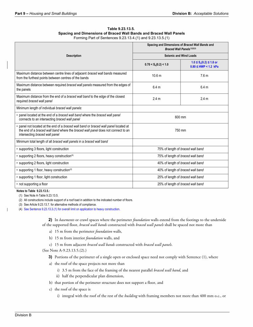
Table 9.23.13.5.Spacing and Dimensions of Braced Wall Bands and Braced Wall Panels
Forming Part of Sentences 9.23.13.4.(1) and 9.23.13.5.(1)
Description
Spacing and Dimensions of Braced Wall Bands and Braced Wall Panels(1)(2)(3)
Seismic and Wind Loads
0.70 < Sa(0.2) < 1.01.0 ≤ Sa(0.2) ≤ 1.8 or
0.80 ≤ HWP < 1.2 kPa
Maximum distance between centre lines of adjacent braced wall bands measured from the furthest points between centres of the bands
10.6 m 7.6 m
Maximum distance between required braced wall panels measured from the edges of the panels
6.4 m 6.4 m
Maximum distance from the end of a braced wall band to the edge of the closest required braced wall panel
2.4 m 2.4 m
Minimum length of individual braced wall panels:
• panel located at the end of a braced wall band where the braced wall panel connects to an intersecting braced wall panel 600 mm
• panel not located at the end of a braced wall band or braced wall panel located at the end of a braced wall band where the braced wall panel does not connect to an intersecting braced wall panel
750 mm
Minimum total length of all braced wall panels in a braced wall band
• supporting 3 floors, light construction 75% of length of braced wall band
• supporting 2 floors, heavy construction(4) 75% of length of braced wall band
• supporting 2 floors, light construction 40% of length of braced wall band
• supporting 1 floor, heavy construction(4) 40% of length of braced wall band
• supporting 1 floor, light construction 25% of length of braced wall band
• not supporting a floor 25% of length of braced wall band
Notes to Table 9.23.13.5.:(1) See Note A-Table 9.23.13.5.(2) All constructions include support of a roof load in addition to the indicated number of floors.(3) See Article 9.23.13.7. for alternative methods of compliance.(4) See Sentence 9.23.13.3.(1) for overall limit on application to heavy construction.
Division B: Acceptable Solutions Part 9 – Housing and Small Buildings
British Columbia Building Code 2018 Division B
ii) constructed with roof framing not more than 400 mm o.c. fastened to the wall framing (see Table 9.23.3.4. and Article 9.23.9.1. for balloon framing).
(See Note A-9.23.13.5.(3).)
4) Walls in detached garages and in accessory buildings serving a single dwelling unit, and the front wall of attached garages serving a single dwelling unit need not comply with Sentence (1) where these walls do not support a floor.
5) Braced wall panels in the braced wall band at the front of an attached garage serving a single dwelling unit need not comply with Sentence (1), provided
a) the maximum spacing between the front of the garage and the back wall of the garage does not exceed 7.6 m,
b) there is not more than one floor above the garage,
c) not less than 50% of the length of the back wall of the garage is constructed of braced wall panels, and
d) not less than 25% of the length of the side walls is constructed of braced wall panels.
9.23.13.6. Materials in Braced Wall Panels
1) Required braced wall panels shall be
a) clad with panel-type cladding complying with Section 9.27. and Table 9.23.3.4.,
b) sheathed with plywood, OSB, waferboard or diagonal lumber sheathing complying with Subsection 9.23.17. and Table 9.23.13.6., and fastened in accordance with Article 9.23.3.5., or
c) finished on the interior with a panel-type material in accordance with the requirements of Section 9.29. and Table 9.23.13.6.
2) Except as provided in Sentence (3), required interior braced wall panels shall be
a) sheathed or finished on both sides with a wood-based material, or
b) finished on both sides with gypsum board.
3) Required interior braced wall panels of wood-based material may be sheathed on one side only, provided
a) the sheathing material is plywood, OSB or waferboard, and
b) the maximum spacing of fasteners along the edge is half of the maximum spacing shown in Table 9.23.3.5.-B.
4) For stacked braced wall bands, where the construction of any one braced wall panel is required to be of a wood-based material, a wood-based material shall be installed in all the required braced wall panels in that braced wall band.
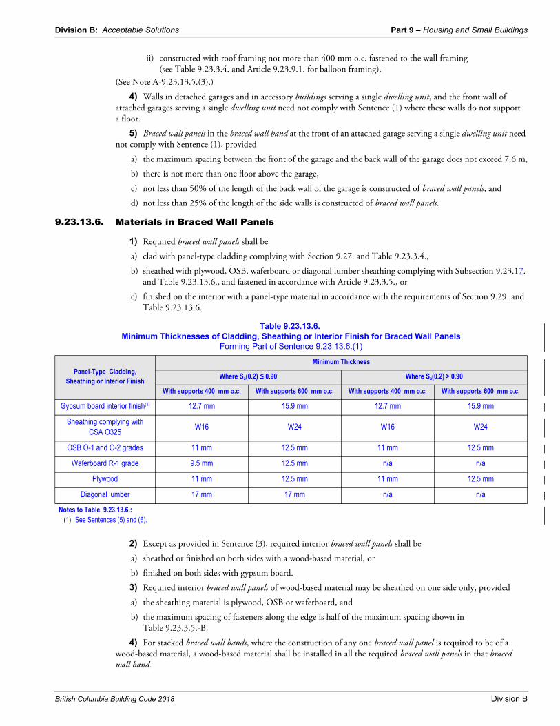
Table 9.23.13.6.Minimum Thicknesses of Cladding, Sheathing or Interior Finish for Braced Wall Panels
Forming Part of Sentence 9.23.13.6.(1)
Panel-Type Cladding, Sheathing or Interior Finish
Minimum Thickness
Where Sa(0.2) ≤ 0.90 Where Sa(0.2) > 0.90
With supports 400 mm o.c. With supports 600 mm o.c. With supports 400 mm o.c. With supports 600 mm o.c.
Gypsum board interior finish(1) 12.7 mm 15.9 mm 12.7 mm 15.9 mm
Sheathing complying with CSA O325
W16 W24 W16 W24
OSB O-1 and O-2 grades 11 mm 12.5 mm 11 mm 12.5 mm
Waferboard R-1 grade 9.5 mm 12.5 mm n/a n/a
Plywood 11 mm 12.5 mm 11 mm 12.5 mm
Diagonal lumber 17 mm 17 mm n/a n/a
Notes to Table 9.23.13.6.:(1) See Sentences (5) and (6).
Part 9 – Housing and Small Buildings Division B: Acceptable Solutions
Division B
5) Gypsum board interior finish shall not be considered as an acceptable sheathing material to provide the required bracing in exterior walls. (See Note A-9.23.13.6.(5) and (6).)
6) At braced wall band spacing intervals of not more than 15 m, braced wall panels shall be constructed with OSB, plywood or diagonal lumber. (See Note A-9.23.13.6.(5) and (6).)
9.23.13.7. Additional System Considerations
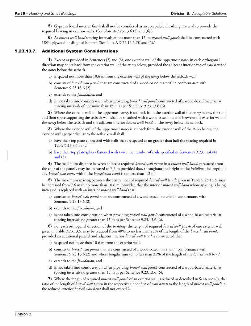
1) Except as provided in Sentences (2) and (3), one exterior wall of the uppermost storey in each orthogonal direction may be set back from the exterior wall of the storey below, provided the adjacent interior braced wall band of the storey below the setback
a) is spaced not more than 10.6 m from the exterior wall of the storey below the setback wall,
b) consists of braced wall panels that are constructed of a wood-based material in conformance with Sentence 9.23.13.6.(2),
c) extends to the foundation, and
d) is not taken into consideration when providing braced wall panels constructed of a wood-based material at spacing intervals of not more than 15 m as per Sentence 9.23.13.6.(6).
2) Where the exterior wall of the uppermost storey is set back from the exterior wall of the storey below, the roof and floor space supporting the setback wall shall be sheathed with a wood-based material between the exterior wall of the storey below the setback and the adjacent interior braced wall bands of the storey below the setback.
3) Where the exterior wall of the uppermost storey is set back from the exterior wall of the storey below, the exterior walls perpendicular to the setback wall shall
a) have their top plate connected with nails that are spaced at no greater than half the spacing required in Table 9.23.3.4., and
b) have their top plate splices fastened with twice the number of nails specified in Sentences 9.23.11.4.(4) and (5).
4) The maximum distance between adjacent required braced wall panels in a braced wall band, measured from the edge of the panels, may be increased to 7.3 m provided that, throughout the height of the building, the length of any braced wall panel within the braced wall band is not less than 1.2 m.
5) The maximum spacing between the centre lines of required braced wall bands given in Table 9.23.13.5. may be increased from 7.6 m to no more than 10.6 m, provided that the interior braced wall band whose spacing is being increased is replaced with an interior braced wall band that
a) consists of braced wall panels that are constructed of a wood-based material in conformance with Sentence 9.23.13.6.(2),
b) extends to the foundation, and
c) is not taken into consideration when providing braced wall panels constructed of a wood-based material at spacing intervals no greater than 15 m as per Sentence 9.23.13.6.(6).
6) For each orthogonal direction of the building, the length of required braced wall panels of one exterior wall given in Table 9.23.13.5. may be reduced from 40% to no less than 25% of the length of the braced wall band, provided an additional parallel and adjacent interior braced wall band is constructed that
a) is spaced not more than 10.6 m from the exterior wall,
b) consists of braced wall panels that are constructed of a wood-based material in conformance with Sentence 9.23.13.6.(2) and whose lengths sum to no less than 25% of the length of the braced wall band,
c) extends to the foundation, and
d) is not taken into consideration when providing braced wall panels constructed of a wood-based material at spacing intervals no greater than 15 m as per Sentence 9.23.13.6.(6).
7) Where the length of required braced wall panels of an exterior wall is reduced as described in Sentence (6), the ratio of the length of braced wall panels in the respective upper braced wall bands to the length of braced wall panels in the reduced exterior braced wall band shall not exceed 2.
Division B: Acceptable Solutions Part 9 – Housing and Small Buildings
British Columbia Building Code 2018 Division B
9.23.14. Roof and Ceiling Framing9.23.14.1. Continuity of Rafters and Joists
1) Roof rafters and joists and ceiling joists shall be continuous or shall be spliced over vertical supports that extend to suitable bearing.
9.23.14.2. Framing around Openings
1) Roof and ceiling framing members shall be doubled on each side of openings greater than 2 rafter or joist spacings wide.
9.23.14.3. End Bearing Length
1) The length of end bearing of joists and rafters shall be not less than 38 mm.
9.23.14.4. Location and Attachment of Rafters
1) Rafters shall be located directly opposite each other and tied together at the peak, or may be offset by their own thickness if nailed to a ridge board not less than 17.5 mm thick.
2) Except as permitted in Sentence (3), framing members shall be connected by gusset plates or nailing at the peak in conformance with Table 9.23.3.4.
3) Where the roof framing on opposite sides of the peak is assembled separately, such as in the case of factory-built houses, the roof framing on opposite sides is permitted to be fastened together with galvanized-steel strips not less than 200 mm by 75 mm by 0.41 mm thick spaced not more than 1.2 m apart and nailed at each end to the framing by at least two 63 mm nails.
9.23.14.5. Shaping of Rafters
1) Rafters shall be shaped at supports to provide even bearing surfaces and supported directly above the exterior walls.
9.23.14.6. Hip and Valley Rafters
1) Hip and valley rafters shall be not less than 50 mm greater in depth than the common rafters and not less than 38 mm thick, actual dimension.
9.23.14.7. Intermediate Support for Rafters and Joists
1) Ceiling joists and collar ties of not less than 38 mm by 89 mm lumber are permitted to be assumed to provide intermediate support to reduce the span for rafters and joists where the roof slope is 1 in 3 or greater.
2) Collar ties referred to in Sentence (1) more than 2.4 m long shall be laterally supported near their centres by not less than 19 mm by 89 mm continuous members at right angles to the collar ties.
3) Dwarf walls and struts are permitted to be used to provide intermediate support to reduce the span for rafters and joists.
4) When struts are used to provide intermediate support they shall be not less than 38 mm by 89 mm material extending from each rafter to a loadbearing wall at an angle of not less than 45° to the horizontal.
5) When dwarf walls are used for rafter support, they shall be framed in the same manner as loadbearing walls and securely fastened top and bottom to the roof and ceiling framing to prevent over-all movement.
6) Solid blocking shall be installed between floor joists beneath dwarf walls referred to in Sentence (5) that enclose finished rooms.
9.23.14.8. Ridge Support
1) Except as provided in Sentence (4), roof rafters and joists shall be supported at the ridge of the roof by
a) a loadbearing wall extending from the ridge to suitable bearing, or
b) a ridge beam supported by not less than 89 mm length of bearing.
Part 9 – Housing and Small Buildings Division B: Acceptable Solutions
Division B
2) Except as provided in Sentence (3), the ridge beam referred to in Sentence (1) shall conform to the sizes and spans shown in Span Table 9.23.4.2.-L, provided
a) the supported rafter or joist length does not exceed 4.9 m, and
b) the roof does not support any concentrated loads.
3) The ridge beam referred to in Sentence (1) need not comply with Sentence (2) where
a) the beam is of not less than 38 mm by 140 mm material, and
b) the beam is supported at intervals not exceeding 1.2 m by not less than 38 mm by 89 mm members extending vertically from the ridge to suitable bearing.
4) When the roof slope is 1 in 3 or more, ridge support need not be provided when the lower ends of the rafters are adequately tied to prevent outward movement.
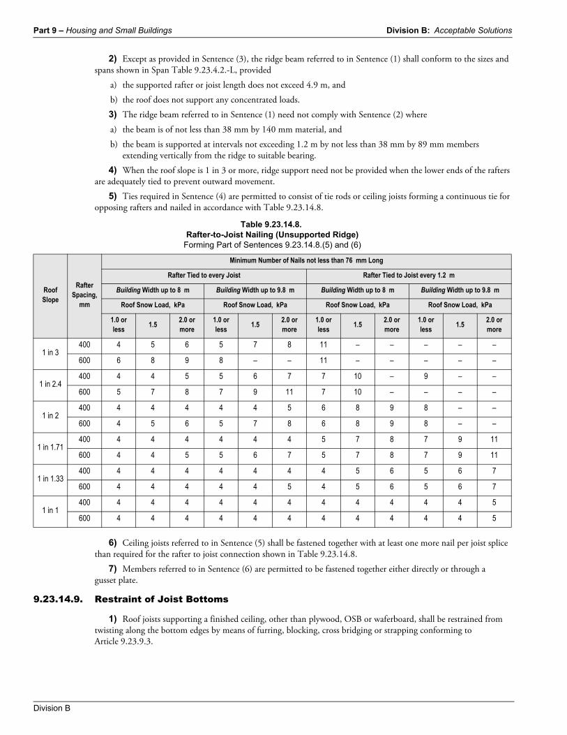
5) Ties required in Sentence (4) are permitted to consist of tie rods or ceiling joists forming a continuous tie for opposing rafters and nailed in accordance with Table 9.23.14.8.
6) Ceiling joists referred to in Sentence (5) shall be fastened together with at least one more nail per joist splice than required for the rafter to joist connection shown in Table 9.23.14.8.
7) Members referred to in Sentence (6) are permitted to be fastened together either directly or through a gusset plate.
9.23.14.9. Restraint of Joist Bottoms
1) Roof joists supporting a finished ceiling, other than plywood, OSB or waferboard, shall be restrained from twisting along the bottom edges by means of furring, blocking, cross bridging or strapping conforming to Article 9.23.9.3.
Table 9.23.14.8.Rafter-to-Joist Nailing (Unsupported Ridge)
Forming Part of Sentences 9.23.14.8.(5) and (6)
Roof Slope
Rafter Spacing,
mm
Minimum Number of Nails not less than 76 mm Long
Rafter Tied to every Joist Rafter Tied to Joist every 1.2 m
Building Width up to 8 m Building Width up to 9.8 m Building Width up to 8 m Building Width up to 9.8 m
Roof Snow Load, kPa Roof Snow Load, kPa Roof Snow Load, kPa Roof Snow Load, kPa
1.0 or less
1.52.0 or more
1.0 or less
1.52.0 or more
1.0 or less
1.52.0 or more
1.0 or less
1.52.0 or more
1 in 3400 4 5 6 5 7 8 11 – – – – –
600 6 8 9 8 – – 11 – – – – –
1 in 2.4400 4 4 5 5 6 7 7 10 – 9 – –
600 5 7 8 7 9 11 7 10 – – – –
1 in 2400 4 4 4 4 4 5 6 8 9 8 – –
600 4 5 6 5 7 8 6 8 9 8 – –
1 in 1.71400 4 4 4 4 4 4 5 7 8 7 9 11
600 4 4 5 5 6 7 5 7 8 7 9 11
1 in 1.33400 4 4 4 4 4 4 4 5 6 5 6 7
600 4 4 4 4 4 5 4 5 6 5 6 7
1 in 1400 4 4 4 4 4 4 4 4 4 4 4 5
600 4 4 4 4 4 4 4 4 4 4 4 5
Division B: Acceptable Solutions Part 9 – Housing and Small Buildings
British Columbia Building Code 2018 Division B
9.23.14.10. Ceiling Joists Supporting Roof Load
1) Except as permitted in Sentence (2), ceiling joists supporting part of the roof load from the rafters shall be not less than 25 mm greater in depth than required for ceiling joists not supporting part of the roof load.
2) When the roof slope is 1 in 4 or less, the ceiling joist sizes referred to in Sentence (1) shall be determined from Span Tables 9.23.4.2.-C to 9.23.4.2.-F and 9.23.4.2.-L for roof joists.
9.23.14.11. Roof Trusses
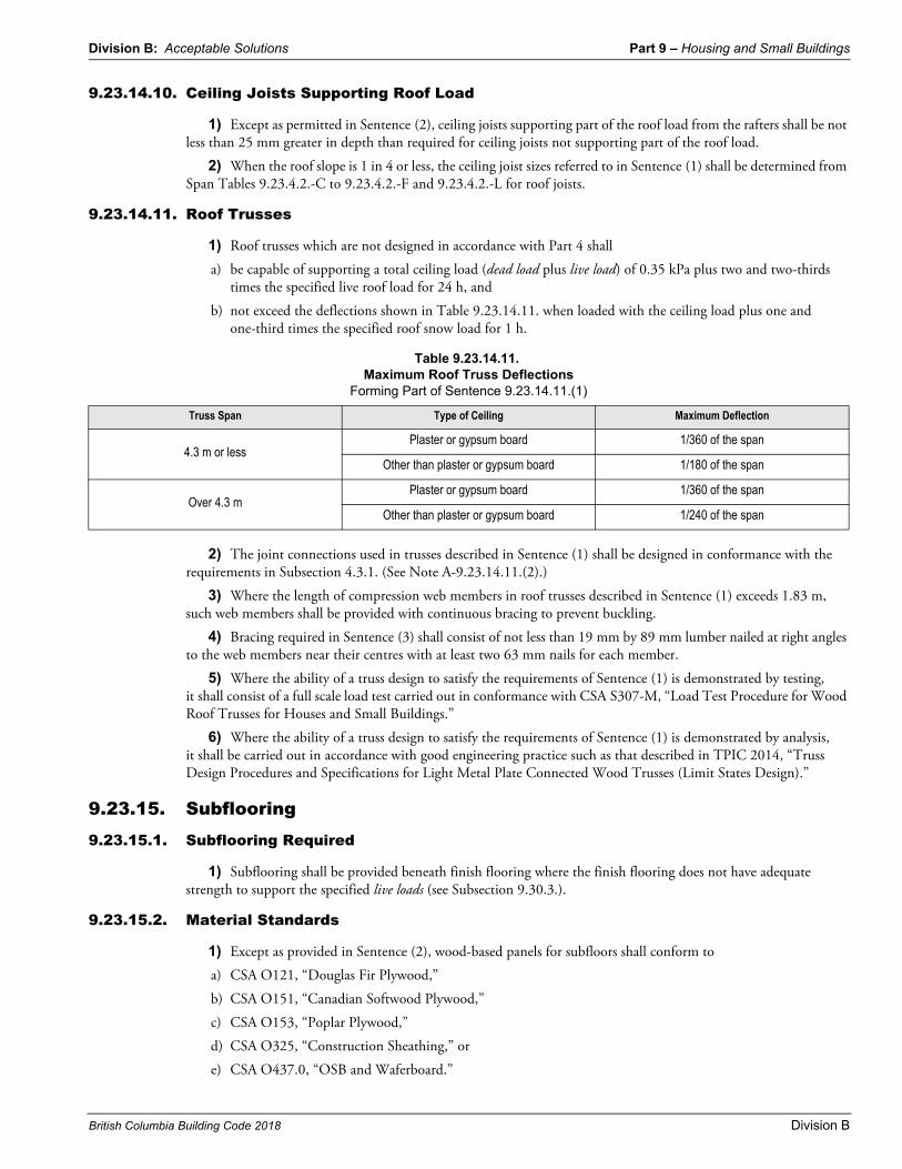
1) Roof trusses which are not designed in accordance with Part 4 shall
a) be capable of supporting a total ceiling load (dead load plus live load) of 0.35 kPa plus two and two-thirds times the specified live roof load for 24 h, and
b) not exceed the deflections shown in Table 9.23.14.11. when loaded with the ceiling load plus one and one-third times the specified roof snow load for 1 h.
2) The joint connections used in trusses described in Sentence (1) shall be designed in conformance with the requirements in Subsection 4.3.1. (See Note A-9.23.14.11.(2).)
3) Where the length of compression web members in roof trusses described in Sentence (1) exceeds 1.83 m, such web members shall be provided with continuous bracing to prevent buckling.
4) Bracing required in Sentence (3) shall consist of not less than 19 mm by 89 mm lumber nailed at right angles to the web members near their centres with at least two 63 mm nails for each member.
5) Where the ability of a truss design to satisfy the requirements of Sentence (1) is demonstrated by testing, it shall consist of a full scale load test carried out in conformance with CSA S307-M, “Load Test Procedure for Wood Roof Trusses for Houses and Small Buildings.”
6) Where the ability of a truss design to satisfy the requirements of Sentence (1) is demonstrated by analysis, it shall be carried out in accordance with good engineering practice such as that described in TPIC 2014, “Truss Design Procedures and Specifications for Light Metal Plate Connected Wood Trusses (Limit States Design).”
9.23.15. Subflooring9.23.15.1. Subflooring Required
1) Subflooring shall be provided beneath finish flooring where the finish flooring does not have adequate strength to support the specified live loads (see Subsection 9.30.3.).
9.23.15.2. Material Standards
1) Except as provided in Sentence (2), wood-based panels for subfloors shall conform to
a) CSA O121, “Douglas Fir Plywood,”
b) CSA O151, “Canadian Softwood Plywood,”
c) CSA O153, “Poplar Plywood,”
d) CSA O325, “Construction Sheathing,” or
e) CSA O437.0, “OSB and Waferboard.”
Table 9.23.14.11.Maximum Roof Truss Deflections
Forming Part of Sentence 9.23.14.11.(1)
Truss Span Type of Ceiling Maximum Deflection
4.3 m or lessPlaster or gypsum board 1/360 of the span
Other than plaster or gypsum board 1/180 of the span
Over 4.3 mPlaster or gypsum board 1/360 of the span
Other than plaster or gypsum board 1/240 of the span
Part 9 – Housing and Small Buildings Division B: Acceptable Solutions
Division B
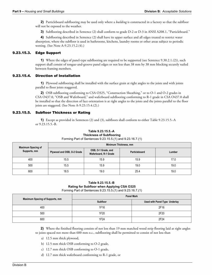
2) Particleboard subflooring may be used only where a building is constructed in a factory so that the subfloor will not be exposed to the weather.
3) Subflooring described in Sentence (2) shall conform to grade D-2 or D-3 in ANSI A208.1, “Particleboard.”
4) Subflooring described in Sentence (2) shall have its upper surface and all edges treated to restrict water absorption, where the subfloor is used in bathrooms, kitchens, laundry rooms or other areas subject to periodic wetting. (See Note A-9.23.15.2.(4).)
9.23.15.3. Edge Support
1) Where the edges of panel-type subflooring are required to be supported (see Sentence 9.30.2.1.(2)), such support shall consist of tongue-and-groove panel edges or not less than 38 mm by 38 mm blocking securely nailed between framing members.
9.23.15.4. Direction of Installation
1) Plywood subflooring shall be installed with the surface grain at right angles to the joists and with joints parallel to floor joists staggered.
2) OSB subflooring conforming to CSA O325, “Construction Sheathing,” or to O-1 and O-2 grades in CSA O437.0, “OSB and Waferboard,” and waferboard subflooring conforming to R-1 grade in CSA O437.0 shall be installed so that the direction of face orientation is at right angles to the joists and the joints parallel to the floor joists are staggered. (See Note A-9.23.15.4.(2).)
9.23.15.5. Subfloor Thickness or Rating
1) Except as provided in Sentences (2) and (3), subfloors shall conform to either Table 9.23.15.5.-A or 9.23.15.5.-B.
2) Where the finished flooring consists of not less than 19 mm matched wood strip flooring laid at right angles to joists spaced not more than 600 mm o.c., subflooring shall be permitted to consist of not less than
a) 12.5 mm thick plywood,
b) 12.5 mm thick OSB conforming to O-2 grade,
c) 12.7 mm thick OSB conforming to O-1 grade,
d) 12.7 mm thick waferboard conforming to R-1 grade, or
Table 9.23.15.5.-AThickness of Subflooring
Forming Part of Sentences 9.23.15.5.(1) and 9.23.16.7.(1)
Maximum Spacing of Supports, mm
Minimum Thickness, mm
Plywood and OSB, O-2 GradeOSB, O-1 Grade, and
Waferboard, R-1 GradeParticleboard Lumber
400 15.5 15.9 15.9 17.0
500 15.5 15.9 19.0 19.0
600 18.5 19.0 25.4 19.0
Table 9.23.15.5.-BRating for Subfloor when Applying CSA O325
Forming Part of Sentences 9.23.15.5.(1) and 9.23.16.7.(1)
Maximum Spacing of Supports, mmPanel Mark
Subfloor Used with Panel-Type Underlay
400 1F16 2F16
500 1F20 2F20
600 1F24 2F24

Division B: Acceptable Solutions Part 9 – Housing and Small Buildings
British Columbia Building Code 2018 Division B
e) OSB conforming to 2R32/2F16 grade.
3) Except where the flooring consists of ceramic tiles applied with adhesive, where a separate panel-type underlay or concrete topping is applied to a subfloor on joists spaced not more than 400 mm o.c., the subfloor is permitted to consist of not less than
a) 12.5 mm thick plywood,
b) 12.5 mm thick OSB conforming to O-2 grade,
c) 12.7 mm thick OSB conforming to O-1 grade,
d) 12.7 mm thick waferboard conforming to R-1 grade, or
e) OSB conforming to 2R32/2F16 grade.
9.23.15.6. Annular Grooved Nails
1) When resilient flooring is applied directly to an OSB, waferboard, particleboard or plywood subfloor, the subfloor shall be fastened to the supports with annular grooved nails.
9.23.15.7. Lumber Subflooring
1) Lumber subflooring shall be laid at an angle of not less than 45° to the joists.
2) Lumber subflooring shall be fully supported at the ends on solid bearing.
3) Lumber for subflooring shall be of uniform thickness and not more than 184 mm wide.
9.23.16. Roof Sheathing9.23.16.1. Required Roof Sheathing
1) Except where the 1-in-50 hourly wind pressure is less than 0.8 kPa and the seismic spectral response acceleration, Sa(0.2), is less than or equal to 0.70, continuous lumber or panel-type roof sheathing shall be installed to support the roofing.
9.23.16.2. Material Standards
1) Wood-based panels used for roof sheathing shall conform to the requirements of
a) CSA O121, “Douglas Fir Plywood,”
b) CSA O151, “Canadian Softwood Plywood,”
c) CSA O153, “Poplar Plywood,”
d) CSA O325, “Construction Sheathing,” or
e) CSA O437.0, “OSB and Waferboard.”
9.23.16.3. Direction of Installation
1) Plywood roof sheathing shall be installed with the surface grain at right angles to the roof framing.
2) OSB roof sheathing conforming to CSA O325, “Construction Sheathing,” or to O-1 and O-2 grades as specified in CSA O437.0, “OSB and Waferboard,” shall be installed with the direction of face orientation at right angles to the roof framing members. (See Note A-9.23.15.4.(2).)
9.23.16.4. Joints in Panel-Type Sheathing
1) Panel-type sheathing board shall be applied so that joints perpendicular to the roof ridge are staggered where
a) the sheathing is applied with the surface grain parallel to the roof ridge, and
b) the thickness of the sheathing is such that the edges are required to be supported.
2) A gap of not less than 2 mm shall be left between sheets of plywood, OSB or waferboard.
Part 9 – Housing and Small Buildings Division B: Acceptable Solutions
Division B
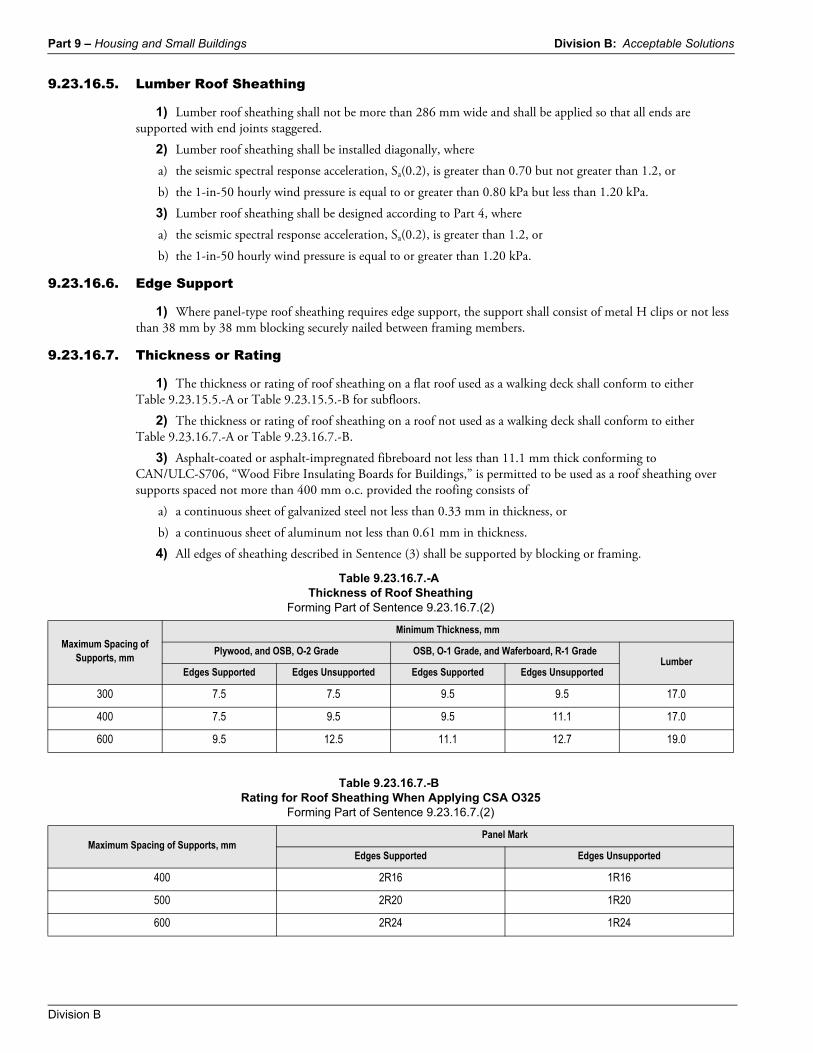
9.23.16.5. Lumber Roof Sheathing
1) Lumber roof sheathing shall not be more than 286 mm wide and shall be applied so that all ends are supported with end joints staggered.
2) Lumber roof sheathing shall be installed diagonally, where
a) the seismic spectral response acceleration, Sa(0.2), is greater than 0.70 but not greater than 1.2, or
b) the 1-in-50 hourly wind pressure is equal to or greater than 0.80 kPa but less than 1.20 kPa.
3) Lumber roof sheathing shall be designed according to Part 4, where
a) the seismic spectral response acceleration, Sa(0.2), is greater than 1.2, or
b) the 1-in-50 hourly wind pressure is equal to or greater than 1.20 kPa.
9.23.16.6. Edge Support
1) Where panel-type roof sheathing requires edge support, the support shall consist of metal H clips or not less than 38 mm by 38 mm blocking securely nailed between framing members.
9.23.16.7. Thickness or Rating
1) The thickness or rating of roof sheathing on a flat roof used as a walking deck shall conform to either Table 9.23.15.5.-A or Table 9.23.15.5.-B for subfloors.
2) The thickness or rating of roof sheathing on a roof not used as a walking deck shall conform to either Table 9.23.16.7.-A or Table 9.23.16.7.-B.
3) Asphalt-coated or asphalt-impregnated fibreboard not less than 11.1 mm thick conforming to CAN/ULC-S706, “Wood Fibre Insulating Boards for Buildings,” is permitted to be used as a roof sheathing over supports spaced not more than 400 mm o.c. provided the roofing consists of
a) a continuous sheet of galvanized steel not less than 0.33 mm in thickness, or
b) a continuous sheet of aluminum not less than 0.61 mm in thickness.
4) All edges of sheathing described in Sentence (3) shall be supported by blocking or framing.
Table 9.23.16.7.-AThickness of Roof Sheathing
Forming Part of Sentence 9.23.16.7.(2)
Maximum Spacing of Supports, mm
Minimum Thickness, mm
Plywood, and OSB, O-2 Grade OSB, O-1 Grade, and Waferboard, R-1 GradeLumber
Edges Supported Edges Unsupported Edges Supported Edges Unsupported
300 7.5 7.5 9.5 9.5 17.0
400 7.5 9.5 9.5 11.1 17.0
600 9.5 12.5 11.1 12.7 19.0
Table 9.23.16.7.-BRating for Roof Sheathing When Applying CSA O325
Forming Part of Sentence 9.23.16.7.(2)
Maximum Spacing of Supports, mmPanel Mark
Edges Supported Edges Unsupported
400 2R16 1R16
500 2R20 1R20
600 2R24 1R24
Division B: Acceptable Solutions Part 9 – Housing and Small Buildings
British Columbia Building Code 2018 Division B
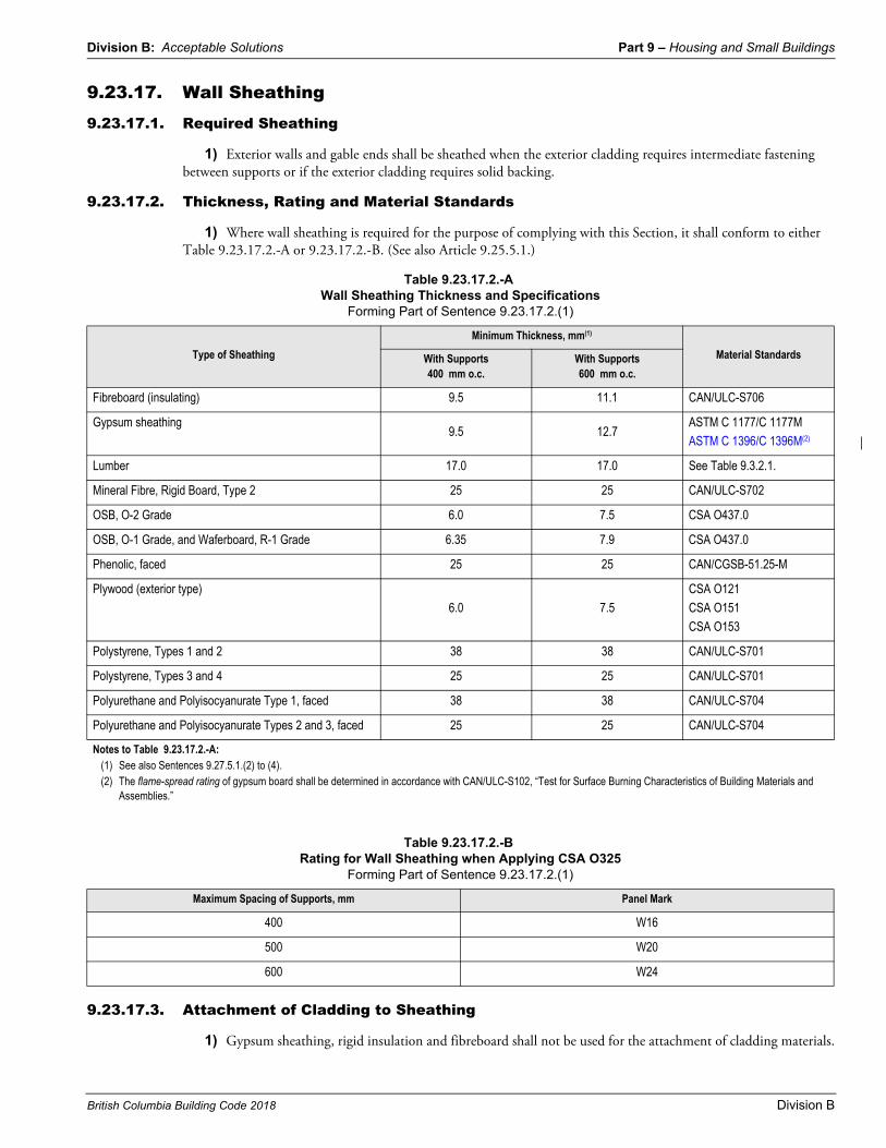
9.23.17. Wall Sheathing9.23.17.1. Required Sheathing
1) Exterior walls and gable ends shall be sheathed when the exterior cladding requires intermediate fastening between supports or if the exterior cladding requires solid backing.
9.23.17.2. Thickness, Rating and Material Standards
1) Where wall sheathing is required for the purpose of complying with this Section, it shall conform to either Table 9.23.17.2.-A or 9.23.17.2.-B. (See also Article 9.25.5.1.)
9.23.17.3. Attachment of Cladding to Sheathing
1) Gypsum sheathing, rigid insulation and fibreboard shall not be used for the attachment of cladding materials.
Table 9.23.17.2.-AWall Sheathing Thickness and Specifications
Forming Part of Sentence 9.23.17.2.(1)
Type of Sheathing
Minimum Thickness, mm(1)
Material StandardsWith Supports 400 mm o.c.
With Supports 600 mm o.c.
Fibreboard (insulating) 9.5 11.1 CAN/ULC-S706
Gypsum sheathing9.5 12.7
ASTM C 1177/C 1177M
ASTM C 1396/C 1396M(2)
Lumber 17.0 17.0 See Table 9.3.2.1.
Mineral Fibre, Rigid Board, Type 2 25 25 CAN/ULC-S702
OSB, O-2 Grade 6.0 7.5 CSA O437.0
OSB, O-1 Grade, and Waferboard, R-1 Grade 6.35 7.9 CSA O437.0
Phenolic, faced 25 25 CAN/CGSB-51.25-M
Plywood (exterior type)
6.0 7.5
CSA O121
CSA O151
CSA O153
Polystyrene, Types 1 and 2 38 38 CAN/ULC-S701
Polystyrene, Types 3 and 4 25 25 CAN/ULC-S701
Polyurethane and Polyisocyanurate Type 1, faced 38 38 CAN/ULC-S704
Polyurethane and Polyisocyanurate Types 2 and 3, faced 25 25 CAN/ULC-S704
Notes to Table 9.23.17.2.-A:(1) See also Sentences 9.27.5.1.(2) to (4).(2) The flame-spread rating of gypsum board shall be determined in accordance with CAN/ULC-S102, “Test for Surface Burning Characteristics of Building Materials and
Assemblies.”
Table 9.23.17.2.-BRating for Wall Sheathing when Applying CSA O325
Forming Part of Sentence 9.23.17.2.(1)
Maximum Spacing of Supports, mm Panel Mark
400 W16
500 W20
600 W24
Part 9 – Housing and Small Buildings Division B: Acceptable Solutions
Division B
9.23.17.4. Lumber Sheathing
1) Lumber wall sheathing shall be applied so that all ends are supported.
2) Where lumber wall sheathing is required to provide bracing according to Article 9.23.10.2., it shall be applied with end joints staggered.
9.23.17.5. Joints in Panel-Type Sheathing
1) A gap of not less than 2 mm shall be left between sheets of plywood, OSB, waferboard or fibreboard.
9.23.17.6. Mansard Style Roofs
1) Where the bottom portions of mansard style roofs are vented, the vertical framing members behind the sloping portions shall be considered on the same basis as exterior wall studs and shall conform to Articles 9.27.3.2. to 9.27.3.6.