Computer Modelling of Materials for Optical and Energy Applications Robert A Jackson Lennard-Jones...
46
Computer Modelling of Materials for Optical and Energy Applications Robert A Jackson Lennard-Jones Laboratories, School of Physical & Geographical Sciences, Keele University, Keele, Staffs ST5 5BG http://www.robajackson.com [email protected] inar to be given at the Institute of Mineralogy, University of Hann 7 February 2014
-
Upload
magnus-parks -
Category
Documents
-
view
214 -
download
1
Transcript of Computer Modelling of Materials for Optical and Energy Applications Robert A Jackson Lennard-Jones...

Computer Modelling of Materials for Optical and Energy Applications
Robert A JacksonLennard-Jones Laboratories,
School of Physical & Geographical Sciences, Keele University, Keele, Staffs ST5 5BG
http://www.robajackson.com
Seminar to be given at the Institute of Mineralogy, University of Hannover7 February 2014

Hannover seminar 7 February 2014 2
Acknowledgements
Tom Littleford, Scott Walker (Keele)Mark Read (Birmingham)
Mário Valerio, Jomar Amaral, Marcos Rezende (UFS, Brazil)Thorsten Schumm (TUWien)
Eric Hudson (UCLA)

Hannover seminar 7 February 2014 3
Talk contents
1. Introduction & motivation2. Methodology3. Modelling dopants in mixed metal fluorides & oxides4. Modelling nuclear fuels5. Modelling zircon & related materials including
radioactive decay products6. Modelling concentration dependence of dopants7. New projects8. Future work

Hannover seminar 7 February 2014 4
Introduction and motivation
• We are interested in using computer modelling to assist in the understanding, design and optimisation of new materials for specific applications.
• Applications of current interest are in optical devices, and materials relevant to nuclear energy generation.
• We have also applied our methods to some geologically important materials.

Hannover seminar 7 February 2014 5
Methodology
• The calculations described today are all based on the use of empirically derived potentials to describe interactions between ions, and methods based on energy minimisation to determine structures and lattice properties.
• We have a long term aim to use quantum mechanics for some specific problems, which will be mentioned at the end of the talk.

Hannover seminar 7 February 2014 6
Interatomic potentials
• Interatomic potentials are simple mathematical functions that describe the interactions between atoms.
• For ionic materials we are describing interionic interactions, and the Buckingham potential is usually used, supplemented by an electrostatic term:V(r) =q1q2/r + A exp (-r/) – Cr-6

Hannover seminar 7 February 2014 7
Empirical fitting
• In the Buckingham potential, the parameters A, and C must be provided, and they are normally obtained by empirical fitting. The q1 and q2 are charges of the interacting ions.
• Empirical fitting involves varying the parameters until the minimum energy structure and properties they predict corresponds to the experimental values.

Hannover seminar 7 February 2014 8
Empirical fitting case study
• An example of detailed potential fitting is available:– M S D Read, R A Jackson, Journal of Nuclear
Materials, 406 (2010) 293–303• In this paper, the potential is fitted to the
structure and lattice properties of UO2.

Hannover seminar 7 February 2014 9

Hannover seminar 7 February 2014
UO2 Experimental Data
S. A. Barrett, A. J. Jacobson, B. C. Tofield, B. E. F. Fender, The Preparation and Structure of Barium Uranium Oxide BaUO3+x, Acta Cryst. 38 (Nov) (1982) 2775–2781.
Elastic Constants / GPa
Reference C11 C12 C44
Dolling et al. [1] 401 ± 9 108 ± 20 67 ± 6
Wachtman et al. [2] 396 ± 1.8 121 ± 1.9 64.1 ± 0.17
Fritz [3] 389.3 ± 1.7 118.7 ± 1.7 59.7 ± 0.3
Dielectric Constants
ReferenceStatic
e0
High Frequency
e∞
Dolling et al. [1] 24 5.3
[1] G. Dolling, R. A. Cowley, A. D. B. Woods, Crystal Dynamics of Uranium Dioxide, Canad. J. Phys. 43 (8) (1965) 1397–1413.
[2] J. B. Wachtman, M. L. Wheat, H. J. Anderson, J. L. Bates, Elastic Constants of Single Crystal UO2 at 25°C, J. Nucl. Mater. 16 (1) (1965) 39–41.
[3] I. J. Fritz, Elastic Properties of UO2 at High-Pressure, J. Appl. Phys. 47 (10) (1976) 4353–4358.
10

Hannover seminar 7 February 2014 11
How good is the final fit?(More details in paper)
Parameter Calc. Obs. D% Parameter Calc. Obs. D%
Lattice Constant [Å] 5.4682 5.4682 0.0 C11 [GPa] 391.4 389.3 0.5
U4+ – U4+
Separation [Å] 3.8666 3.8666 0.0 C12 [GPa] 116.7 118.7 -1.7
U4+ – O2-
Separation [Å] 2.3678 2.3678 0.0 C44 [GPa] 58.1 59.7 -2.7
O2- – O2-
Separation [Å] 2.7341 2.7341 0.0 Bulk Modulus [GPa] 208.3 204.0 2.1
Static Dielectric Constant 24.8 24.0 3.3 High Frequency
Dielectric Constant 5.0 5.3 -5.7
Note that it is unusual to have this amount of data to fit to!

Hannover seminar 7 February 2014 12
Defects in materials
• Most interesting properties are due to the presence of defects!
• The picture shows a sample of amethyst, which is quartz, SiO2 doped with Fe3+ ions from Fe2O3.
• The value of the quartz is drastically increased by the presence of a very small number of Fe3+ ions!

Hannover seminar 7 February 2014 13
Defect calculations
• We are mainly interested in:Calculation of energies of formation of defectsModelling ion migrationModelling doping in crystals
Calculating substitution and solution energies Determining location of dopantsDetermining dopant concentrations (new)
• Point defect calculations generally use the Mott-Littleton approximation:

14
Mott-Littleton approximation
Region IIons are strongly perturbed by the defect and are relaxed explicitly with respect to their Cartesian coordinates.
Region IIIons are weakly perturbed and therefore their displacements, with the associated energy of relaxation, can be approximated.
Region IIa
DefectRegion I
© Mark Read
Hannover seminar 7 February 2014

Substitution and solution energies
• Substitution energies are the energies involved in substituting an ion into the material, but they do not take into account all the energetic terms involved in the solution process.
• Solution energies include all these terms, so they can be used to determine where the ion will substitute, and what form of charge compensation will occur (if it is needed).
Hannover seminar 7 February 2014 15

Hannover seminar 7 February 2014 16
Application: nuclear clocks
• 229Th is being investigated for use in ‘nuclear clocks’; its first nuclear excited state is (unusually) only ~ 8 eV above the ground state, and can be probed by VUV radiation.
• Nuclear clocks promise up to 6 orders of magnitude improvement in precision over next generation atomic clocks, as well as enhanced stability.
• Th has to be doped into a suitable crystal.

Hannover seminar 7 February 2014 17
Candidate crystals for Th doping
• LiCaAlF6 and LiSrAlF6 are being investigated, as is CaF2.
• This is a collaboration with two groups, in UCLA and Vienna, where crystal growth is being carried out.
• 229Th costs $50k/mg, so the cheaper 232 isotope is being used initially!

Hannover seminar 7 February 2014 18
Case study: modelling Th4+ in LiCaAlF6
• Aim: to illustrate all the steps involved in a study of doping a material.1. Derive and test a potential for LiCaAlF6.
2. Derive and test a potential for ThF4.
3. From defect calculations, determine preferred location of Th4+, and the charge compensation involved.

Hannover seminar 7 February 2014 19
Journal of Physics: Condensed Matter 21 (2009) 325403
Hannover seminar 7 February 2014 20
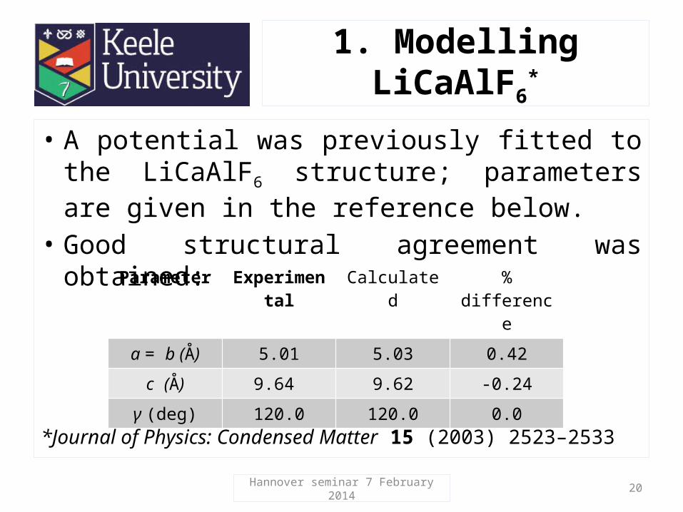
1. Modelling LiCaAlF6*
• A potential was previously fitted to the LiCaAlF6 structure; parameters are given in the reference below.
• Good structural agreement was obtained:
*Journal of Physics: Condensed Matter 15 (2003) 2523–2533
Parameter Experimental Calculated % difference
a = b (Å) 5.01 5.03 0.42
c (Å) 9.64 9.62 -0.24
γ (deg) 120.0 120.0 0.0

Hannover seminar 7 February 2014 21
2. Modelling ThF4
• A potential was fitted to the ThF4 structure, giving agreement as shown below:
[1] G Benner and B G Mueller, Zeitschrift für Anorganische und Allgemeine Chemie 588 (1990) 33-42
• Potential parameters are given in the 2009 JPCM reference (slide 19).
Experimental [1]
Simulated % difference
A (Å) 13.049 13.089 0.31 B (Å) 11.120 10.993 -1.15 C (Å) 8.538 8.546 0.09 ( ) 126.31 125.80 -0.41

Hannover seminar 7 February 2014 22
3. Where does Th substitute in LiCaAlF6?
• Whichever cation site Th4+ substitutes at in this material, charge compensation will be needed.
• 10 possible reaction schemes were considered, and solution energies were calculated for each one.
• The lowest energy scheme involves substitution at the Ca2+ site, with charge compensation by 2 fluorine interstitial ions:ThF4 + CaCa → ThCa
+ 2Fi’ + CaF2

Hannover seminar 7 February 2014 23
Solution energies (eV) for different solution schemes
1.95 1.96 2.84 2.15 1.20 1.47 1.95
... '''
Li AlTh V ... '''3Li Li
Th V ... ' ''
Li CaLiTh V V .. '''
Ca CaTh V .. '2Ca LiTh V .. '''3 2
Ca AlTh V. '
Al LiTh V
Charge compensation by vacancies
½ ½ 0 ½ 0 0 ¼ ¼ 0 ¾ ½ 0½ ½ 0½ 0 0
½ ½ 0¼ ¼ 0
½ ½ 0¾ ½ 0
½ 0 0¼ ¼ 0
½ 0 0¾ ½ 0
¼ ¼ 0¾ ½ 0
2.36 2.43 2.46 2.24 0.97 1.00 0.83 1.08 0.98 0.96
. '
Al iTh F .. '2Ca iTh F
Charge compensation by interstitials

Hannover seminar 7 February 2014 24
Conclusions on case study
• From solution energy calculations, Th4+ is predicted to substitute at the Ca2+ site, with charge compensation by F- interstitials.
• This is an important result because of the possible effects of charge compensating defects on the optical properties of the doped material.
• Crystal growth is in progress, using 232Th initially.

25
232Th doped CaF2: see http://www.thorium.at/?p=481229Thorium-doped calcium fluoride for nuclear laser spectroscopy:P Dessovic, P Mohn, R A Jackson, G Winkler, M Schreitl, G Kazakov and T Schumm, JPCM 2014 in press
Hannover seminar 7 February 2014
Green because of the colour of the laser pointer!
Th-CaF2 project*

Hannover seminar 7 February 2014 26
Modelling pure & defective surfaces of mixed metal fluorides(Tom Littleford’s PhD)
• Surfaces and crystal morphologies may be modelled using the METADISE code written by Steve Parker.
• Morphologies can be calculated based on surface or attachment energies, giving equilibrium or growth morphologies.
• Dopants can then be added at surfaces and their effect on morphology assessed.

YLF Morphology
Hannover seminar 7 February 2014 27

28
YLF morphology as affected by Ce dopants
Hannover seminar 7 February 2014
Ce-YLF

29
Relative effect on surfaces
Hannover seminar 7 February 2014
The presence of Ce modifies the morphology as shown. The (011) surface becomes less prominent with the (111) surface disappearing altogether. The 021 surface is stabilised by Ce dopants and therefore appears in the defective morphology.

Hannover seminar 7 February 2014 30
Modelling nuclear fuels(Scott Walker’s PhD)
• The derivation of a potential for UO2 has already been discussed.
• Having previously worked on nuclear materials in the 1980s, interest in nuclear power has returned (at least in some countries!), and there is new motivation for research.
• We are studying UO2 and PuO2, and the mixed oxide MOX.
• A paper describing the derivation of a potential for PuO2 has just been accepted for publication.

Hannover seminar 7 February 2014 31
History!

Hannover seminar 7 February 2014 32
Approaches to modelling MOX (& doped materials)
• We use two approaches to model materials with a finite dopant concentrations:– the Mean Field method, which assumes an
average occupancy of the dopant ion– the Supercell method, in which the dopant ions
are substituted for host ions in a supercell• The second method is more flexible, allowing
different configurations of dopants, and might be expected to give more reliable results.

The MOX system UO2/PuO2 was modelled for a range of Pu concentrations allowing the variation of lattice parameter with Pu concentration to be predicted. As expected, lattice parameter decreases linearly with increasing Pu concentration
Two methods were employed in this particular study. The first a Mean Field method which considers an average Pu occupancy at each U site; the second a Supercell method, where Pu ions are explicitly substituted for U ions in the cell. Both produce the same result.
Mean Field vs. Supercell Approach
Hannover seminar 7 February 2014 33

Hannover seminar 7 February 2014 34
• Zircon, ZrSiO4, readily accommodates U at the Zr site, and the fully substituted compound, USiO4, is the mineral coffinite.
• Starting with zircon and progressively substituting U at the Zr site allows the structure of coffinite to be predicted, and the result can be compared with the experimental structure:
Modelling zircon and related materials

Hannover seminar 7 February 2014 35
Structure prediction of coffinite
• The structure is predicted to better than -2%
• Structures for the full range of solid solutions can be calculated.
Predicted coffinite structure
Exp (Å) Calc (Å) %
a=b 6.995 6.874 -1.8
c 6.262 6.371 -1.7
Black, interstitial coffinite cementing a sub-angular quartzose sandstone. Schumacher Coll.(Temple Mountain, San Rafael District (San Rafael Swell), Emery Co., Utah, USA)

36
Coffinite and radioactive decay
• 238U decays radioactively to 206Pb (see next slide).
• Due to the long t1/2 of U (& subsequent nuclides), oldest samples of coffinite have ~ 3% Pb.
• However, the structure of the end member, PbSiO4, can be predicted, as can the full Pb-U solid solution.
PbSiO4
Exp (Å) Calc (Å) %a=b ? 6.489
c ? 6.102
Experimental data may take a while to obtain (:
Attempted synthesis of PbSiO4 (Keelite) is being attempted!
Hannover seminar 7 February 2014

37
238U decay series
Hannover seminar 7 February 2014

Hannover seminar 7 February 2014 38
Modelling concentration dependence of doping
• Motivation – for optical materials, dopants are responsible for their important properties
• We can predict where they substitute in the lattice, and what form of charge compensation will be preferred.
• We would like to be able to predict how much dopant can be added!
• We are developing a method to do this …

Hannover seminar 7 February 2014 39
Explanation of method(i)
• Consider doping YLiF4 (YLF) with M3+ dopants:
(1-x) YF3 + xMF3 + LiF → Y1-xMxLiF4
• The procedure is to calculate the energy of this reaction as a function of the dopant concentration x. This gives:
Esol = E (Y1-xMxLiF4) – [(1-x) Elatt(YF3)+ xElatt(MF3)+ Elatt(LiF)]
• The correct way to calculate the first term in this equation has taken a lot of thought!

Hannover seminar 7 February 2014 40
Explanation of method(ii)
• The term is calculated using this expression:ED(x) = x ED
ML + Ep(1)• This splits the energy into defective and
perfect terms (and assumes they don’t interact).
• The final expression is then:Esol = E (xED
ML + Elatt(YLiF4) – [(1-x) Elatt(YF3)+ xElatt(MF3)+ Elatt(LiF)]
• The method has been tested:

Hannover seminar 7 February 2014 41
Defect concentration results*
RE Max % MF3
RE Max % MF3
La 0.69 Tb 1.41
Ce 0.76 Dy 1.28
Pr 0.85 Ho 1.40
Nd 0.93 Er 1.52
Sm 1.23 Tm 1.33
Eu 1.15 Yb 1.51
Gd 1.22 Lu 1.49
• The results show a general increase in max. defect concentration with atomic number.
• We are looking for experimental results to test this method on…
• Supercell methods can also be used to calculate the RHS term.
* Tom Littleford: unpublished results

Hannover seminar 7 February 2014 42
Recently started projects
• Modelling of Na(B(OH)4) – deriving a potential to model the structure and properties of the material.– Z Assi, C Rüscher (Hannover)
• Modelling of laser cooling in TM-doped YLiF4.– M P Hehlen (Los Alamos NL)
• Modelling of finite dopant concentrations in LiNbO3
– M E G Valerio (UFS), G Borchardt, P Fielitz (Clausthal)

Hannover seminar 7 February 2014 43
Future work
• Further development of the dopant concentration work.
• We are interested in calculating the electronic structure of dopants in optical materials, with a view to predicting energy transitions.
• This has already been done with crystal field methods, but the ultimate aim is to use embedded cluster quantum mechanical approaches.

Hannover seminar 7 February 2014 44
Some information about a future conference of possible interest!

Hannover seminar 7 February 2014 45
Some of the team

Hannover seminar 7 February 2014 46
Thank you!
28/11/12