CNC Precision Automatic Lathe - remsales.com · Optimized tooling with the help of a BH automatic...
12
CNC Precision Automatic Lathe Sliding headstock type automatic lathe that encompasses the entire process 12-station turret + Gang type tool post + Back spindle
Transcript of CNC Precision Automatic Lathe - remsales.com · Optimized tooling with the help of a BH automatic...
External View
CAT.NO.E112524.JUN.3T(H)
External View
12-20, TOMIZAWA-CHO, NIHONBASHI, CHUO-KU, TOKYO 103-0006, JAPANPhone : 03-3808-1172Facsimile : 03-3808-1175
1,733
1,000 (Center height)
1,910(560)
570
3,040
520
(160)
700
185
425
(20)
1,585
2,480
1,405
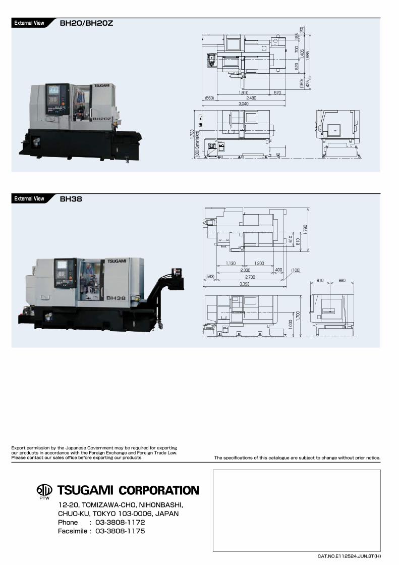
CNC Precision Automatic Lathe
Sliding headstock type automatic lathe that encompasses the entire process12-station turret + Gang type tool post + Back spindle
BH20/BH20Z
BH38
Export permission by the Japanese Government may be required for exportingour products in accordance with the Foreign Exchange and Foreign Trade Law.Please contact our sales office before exporting our products. The specifications of this catalogue are subject to change without prior notice.
980810
1,000 1,700
1,130 1,2002,330 400
2,730
610
810
1,790
3,393
(100)(563)
32
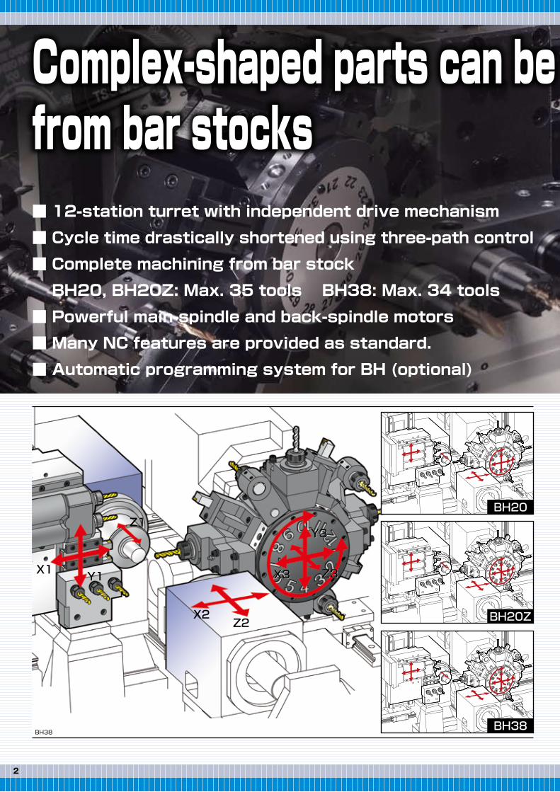
■ 12-station turret with independent drive mechanism
■ Cycle time drastically shortened using three-path control
■ Complete machining from bar stock
BH20, BH20Z: Max. 35 tools BH38: Max. 34 tools
■ Powerful main-spindle and back-spindle motors
■ Many NC features are provided as standard.
■ Automatic programming system for BH (optional)
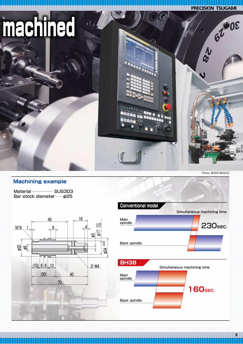
Machining example
Material SUS303Bar stock diameter φ25
Complex-shaped parts can be machinedfrom bar stocks
BH20
BH20Z
BH38
Conventional model
230sec.
Simultaneous machining time
Mainspindle
Back spindle
Mainspindle
BH38
160sec.
Simultaneous machining time
Back spindle
BH38
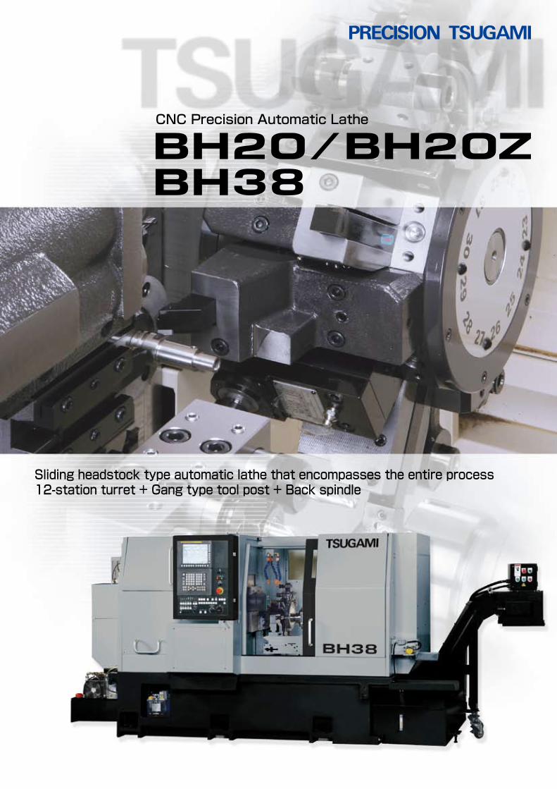
Photo: BH20/BH20Z
X3
Y3
Z3X1
X2
X3
Y3
Z3X3
Y3
Z3
Z2
Y1
Z1
70
18
φ17
-0.01
-0.03
φ24
±0.03
40(30)
105(10)
φ3
1
2-M4
6
φ8
45
φ22
M16 4
5
32
■ 12-station turret with independent drive mechanism
■ Cycle time drastically shortened using three-path control
■ Complete machining from bar stock
BH20, BH20Z: Max. 35 tools BH38: Max. 34 tools
■ Powerful main-spindle and back-spindle motors
■ Many NC features are provided as standard.
■ Automatic programming system for BH (optional)
Machining example
Material SUS303Bar stock diameter φ25
Complex-shaped parts can be machinedfrom bar stocks
BH20
BH20Z
BH38
Conventional model
230sec.
Simultaneous machining time
Mainspindle
Back spindle
Mainspindle
BH38
160sec.
Simultaneous machining time
Back spindle
BH38
Photo: BH20/BH20Z
X3
Y3
Z3X1
X2
X3
Y3
Z3X3
Y3
Z3
Z2
Y1
Z1
70
18
φ17
-0.01
-0.03
φ24
±0.03
40(30)
105(10)
φ3
1
2-M4
6
φ8
45
φ22
M16 4
5
"Double Spindle" structure
54
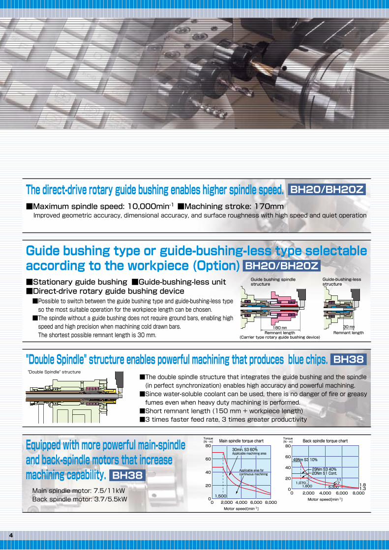
The direct-drive rotary guide bushing enables higher spindle speed.■Maximum spindle speed: 10,000min-1 ■Machining stroke: 170mm Improved geometric accuracy, dimensional accuracy, and surface roughness with high speed and quiet operation
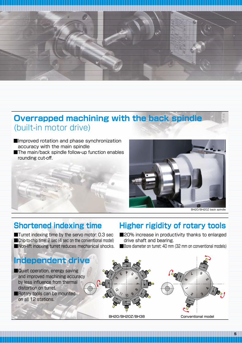
Overrapped machining with the back spindle (built-in motor drive)■Improved rotation and phase synchronization accuracy with the main spindle■The main/back spindle follow-up function enables rounding cut-off.
■Possible to switch between the guide bushing type and guide-bushing-less type so the most suitable operation for the workpiece length can be chosen.■The spindle without a guide bushing does not require ground bars, enabling high speed and high precision when machining cold drawn bars. The shortest possible remnant length is 30 mm.
Guide bushing spindle structure
Remnant length(Carrier type rotary guide bushing device)
■Stationary guide bushing■Direct-drive rotary guide bushing device
■Guide-bushing-less unit
Guide bushing type or guide-bushing-less type selectable according to the workpiece (Option)
"Double Spindle" structure enables powerful machining that produces blue chips.
Equipped with more powerful main-spindle and back-spindle motors that increase machining capability.
■The double spindle structure that integrates the guide bushing and the spindle (in perfect synchronization) enables high accuracy and powerful machining. ■Since water-soluble coolant can be used, there is no danger of fire or greasy fumes even when heavy duty machining is performed.■Short remnant length (150 mm + workpiece length)■3 times faster feed rate, 3 times greater productivity
Guide-bushing-less structure
Remnant length
BH20/BH20Z/BH38
543
21
12
11 9
87
6
10
Conventional model
1
2 3
45
67
8
■Turret indexing time by the servo motor: 0.3 sec■Chip-to-chip time: 2 sec (4 sec on the conventional model)■Non-lift indexing turret reduces mechanical shocks.
■Quiet operation, energy saving and improved machining accuracy by less influence from thermal distortion on turret.■Rotary tools can be mounted on all 12 stations.
■20% increase in productivity thanks to enlarged drive shaft and bearing.■Bore diameter on turret: 40 mm (32 mm on conventional models)
Independent drive
Shortened indexing time Higher rigidity of rotary toolsBH38
BH38
BH20/BH20Z back spindle
Main spindle motor: 7.5/11kWBack spindle motor: 3.7/5.5kW
BH20/BH20Z
BH20/BH20Z
180 mm 30 mm
Back spindle torque chartTorque[N・m]
Motor speed[min-1]
Motor speed[min-1]
80
60
40
20
00
80
60
40
20
00
2,000 4,000 6,000 8,000
2,000 4,000 6,000 8,000
Main spindle torque chartTorque[N・m]
30min. S3 60%Applicable machining area
Applicable area forcontinuous machining
1,500
1,0701,800 5,000
117 1.8
1.3
49Nm S3 10%
29Nm S3 40%20Nm S1 Cont.
"Double Spindle" structure
54
The direct-drive rotary guide bushing enables higher spindle speed.■Maximum spindle speed: 10,000min-1 ■Machining stroke: 170mm Improved geometric accuracy, dimensional accuracy, and surface roughness with high speed and quiet operation
Overrapped machining with the back spindle (built-in motor drive)■Improved rotation and phase synchronization accuracy with the main spindle■The main/back spindle follow-up function enables rounding cut-off.
■Possible to switch between the guide bushing type and guide-bushing-less type so the most suitable operation for the workpiece length can be chosen.■The spindle without a guide bushing does not require ground bars, enabling high speed and high precision when machining cold drawn bars. The shortest possible remnant length is 30 mm.
Guide bushing spindle structure
Remnant length(Carrier type rotary guide bushing device)
■Stationary guide bushing■Direct-drive rotary guide bushing device
■Guide-bushing-less unit
Guide bushing type or guide-bushing-less type selectable according to the workpiece (Option)
"Double Spindle" structure enables powerful machining that produces blue chips.
Equipped with more powerful main-spindle and back-spindle motors that increase machining capability.
■The double spindle structure that integrates the guide bushing and the spindle (in perfect synchronization) enables high accuracy and powerful machining. ■Since water-soluble coolant can be used, there is no danger of fire or greasy fumes even when heavy duty machining is performed.■Short remnant length (150 mm + workpiece length)■3 times faster feed rate, 3 times greater productivity
Guide-bushing-less structure
Remnant length
BH20/BH20Z/BH38
543
21
12
11 9
87
6
10
Conventional model
1
2 3
45
67
8
■Turret indexing time by the servo motor: 0.3 sec■Chip-to-chip time: 2 sec (4 sec on the conventional model)■Non-lift indexing turret reduces mechanical shocks.
■Quiet operation, energy saving and improved machining accuracy by less influence from thermal distortion on turret.■Rotary tools can be mounted on all 12 stations.
■20% increase in productivity thanks to enlarged drive shaft and bearing.■Bore diameter on turret: 40 mm (32 mm on conventional models)
Independent drive
Shortened indexing time Higher rigidity of rotary toolsBH38
BH38
BH20/BH20Z back spindle
Main spindle motor: 7.5/11kWBack spindle motor: 3.7/5.5kW
BH20/BH20Z
BH20/BH20Z
180 mm 30 mm
Back spindle torque chartTorque[N・m]
Motor speed[min-1]
Motor speed[min-1]
80
60
40
20
00
80
60
40
20
00
2,000 4,000 6,000 8,000
2,000 4,000 6,000 8,000
Main spindle torque chartTorque[N・m]
30min. S3 60%Applicable machining area
Applicable area forcontinuous machining
1,500
1,0701,800 5,000
117 1.8
1.3
49Nm S3 10%
29Nm S3 40%20Nm S1 Cont.
76
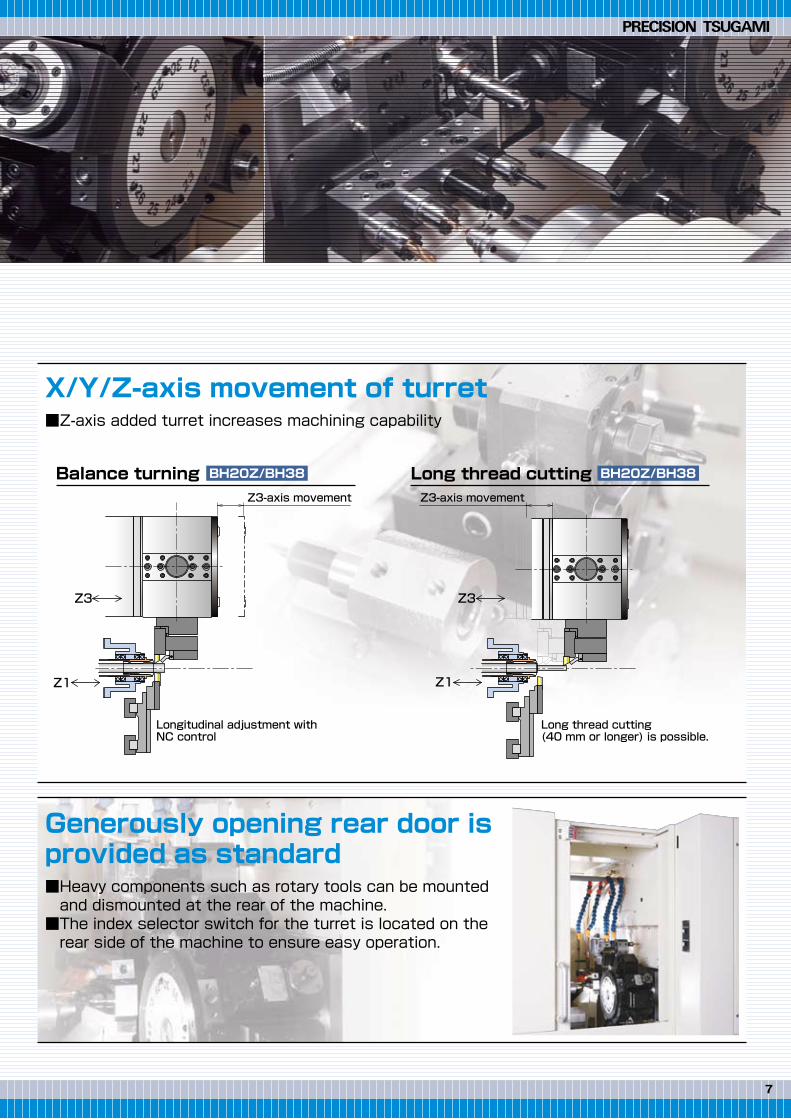
Long thread cutting
Long thread cutting (40 mm or longer) is possible.
Z3
Z1
Balance turning
Longitudinal adjustment with NC control
Z3
Z1
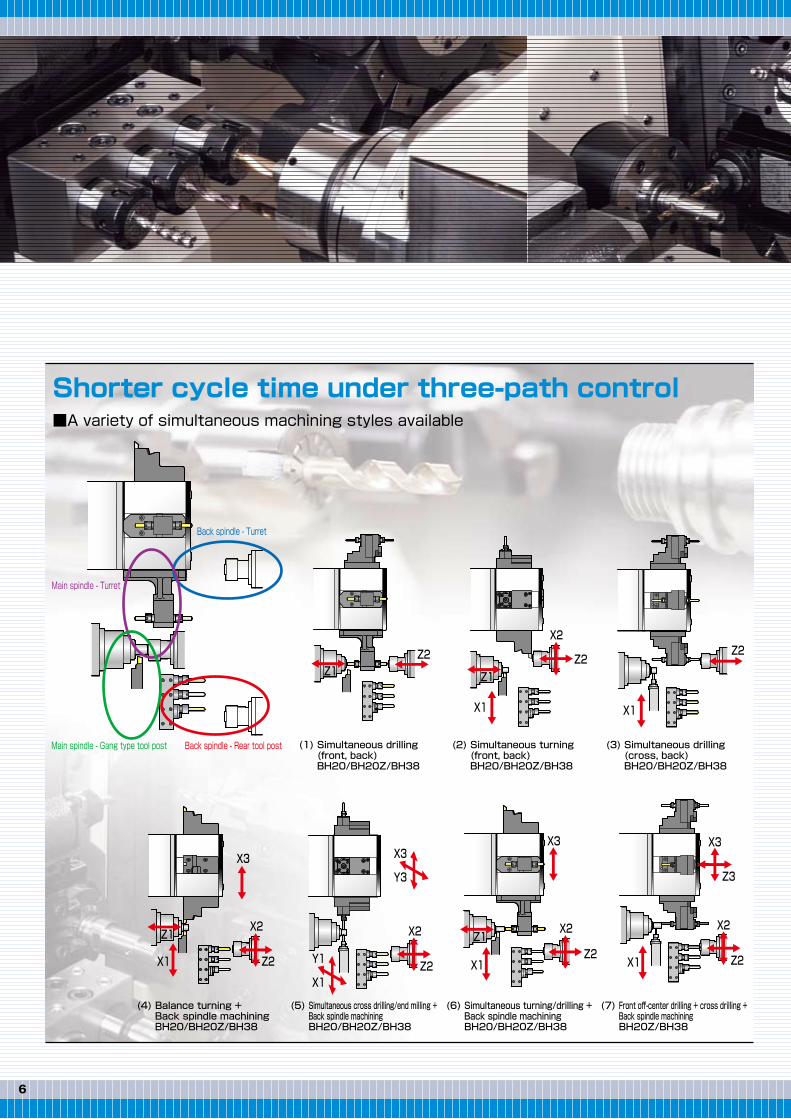
(1) Simultaneous drilling (front, back) BH20/BH20Z/BH38
(2) Simultaneous turning (front, back) BH20/BH20Z/BH38
(3) Simultaneous drilling (cross, back) BH20/BH20Z/BH38
(5) Simultaneous cross drilling/end milling + Back spindle machining BH20/BH20Z/BH38
(4) Balance turning + Back spindle machining BH20/BH20Z/BH38
(6) Simultaneous turning/drilling + Back spindle machining BH20/BH20Z/BH38
(7) Front off-center drilling + cross drilling + Back spindle machining BH20Z/BH38
Back spindle - Rear tool postMain spindle - Gang type tool post
Shorter cycle time under three-path control■A variety of simultaneous machining styles available
X/Y/Z-axis movement of turret■Z-axis added turret increases machining capability
Generously opening rear door is provided as standard■Heavy components such as rotary tools can be mounted and dismounted at the rear of the machine. ■The index selector switch for the turret is located on the rear side of the machine to ensure easy operation.
Z3-axis movement Z3-axis movement
Z1Z2
X1
Z2
Main spindle - Turret
Back spindle - Turret
X1
Z2
X2
X1 Z2
X2
Z3
X3
X1Z2
X2
X3
X1
X3
Z2
X2
X1
Y1
Y3
X3
X2
Z2
BH20Z/BH38 BH20Z/BH38
Z1
Z1Z1
76
Long thread cutting
Long thread cutting (40 mm or longer) is possible.
Z3
Z1
Balance turning
Longitudinal adjustment with NC control
Z3
Z1
(1) Simultaneous drilling (front, back) BH20/BH20Z/BH38
(2) Simultaneous turning (front, back) BH20/BH20Z/BH38
(3) Simultaneous drilling (cross, back) BH20/BH20Z/BH38
(5) Simultaneous cross drilling/end milling + Back spindle machining BH20/BH20Z/BH38
(4) Balance turning + Back spindle machining BH20/BH20Z/BH38
(6) Simultaneous turning/drilling + Back spindle machining BH20/BH20Z/BH38
(7) Front off-center drilling + cross drilling + Back spindle machining BH20Z/BH38
Back spindle - Rear tool postMain spindle - Gang type tool post
Shorter cycle time under three-path control■A variety of simultaneous machining styles available
X/Y/Z-axis movement of turret■Z-axis added turret increases machining capability
Generously opening rear door is provided as standard■Heavy components such as rotary tools can be mounted and dismounted at the rear of the machine. ■The index selector switch for the turret is located on the rear side of the machine to ensure easy operation.
Z3-axis movement Z3-axis movement
Z1Z2
X1
Z2
Main spindle - Turret
Back spindle - Turret
X1
Z2
X2
X1 Z2
X2
Z3
X3
X1Z2
X2
X3
X1
X3
Z2
X2
X1
Y1
Y3
X3
X2
Z2
BH20Z/BH38 BH20Z/BH38
Z1
Z1Z1
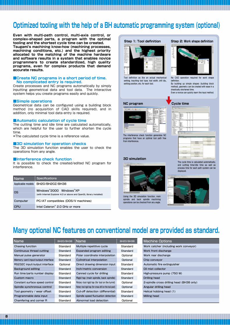
Even with multi-path control, multi-axis control, or complex-shaped parts, a program with the optimal tooling and the shortest cycle time can be created.Tsugami's machining know-how (machining processes, machining conditions, etc.) and the highest priority allocated to the matching of the machine hardware and software results in a system that enables novice programmers to create standardized, high quality programs, even for complex products that demand accurate results.
Optimized tooling with the help of a BH automatic programming system (optional)
■Create NC programs in a short period of time. No complicated entry is required.Create processes and NC programs automatically by simply inputting geometrical data and tool data. The interactive system helps you create programs easily and quickly.
■Simple operationsGeometrical data can be configured using a building block method (no acquisition of CAD skills required), and in addition, only minimal tool data entry is required.
■Automatic calculation of cycle timeThe cutting time and idle time are calculated automatically, which are helpful for the user to further shorten the cycle time.*The calculated cycle time is a reference value.
■3D simulation for operation checksThe 3D simulation function enables the user to check the operations from any angle.
■Interference check functionIt is possible to check the created/edited NC program for interference.
Many optional NC features on conventional model are provided as standard.
Name Specifications
The cycle time is calculated automatically, and cutting time/idle time as well as process time for each path system can be displayed.
The interference check function generates NC programs that have an optimal tool path free from interference.
Using the 3D simulation function, main spindle and back spindle machining operations can be checked from any angle.
Tool definition as like an actual mechanical setting, inputting tool type, tool width, drill dia., setting position, etc. for each tool.
No CAD operation required for work shape definition.By building up simple shapes (building block method), geometry can be created with ease in a drastically shortened time.Even a novice can quickly learn the input method.
Step 1: Tool definition Step 2: Work shape definition
NC program Cycle time
3D simulation
98
Applicable models
OS
Computer
BH20/BH20Z/BH38
WindowsⓇ2000 WindowsⓇXP(with Internet Explorer 4.0 or above and OpenGL library installed)
PC/AT compatibles (DOS/V machines)
CPU Intel CeleronⓇ 2.0 GHz or more
Chasing function
Continuous thread cutting
Manual pulse generator
Memory card input/output interface
RS232C input/output interface
Background editing
Run time/parts number display
Custom macro
Constant surface speed control
Spindle synchronous control
Tool geometry / wear offset
Programmable data input
Chamfering and corner R
Standard
Standard
Standard
Standard
Optional
Standard
Standard
Standard
Standard
Standard
Standard
Standard
Standard
Standard
Standard
Optional
Optional
Standard
Standard
Standard
Standard
Optional
Optional
Standard
Standard
Optional
Multiple repetitive cycle
Expanded program editing
Polar coordinate interpolation
Cylindrical interpolation
Direct drawing dimension input
Inch/metric conversion
Canned cycle for drilling
Rigid tap (main spindle, back spindle)
Rotary tool rigid tap (for tool on the turret)
Rotary tool rigid tap (for cross drill on the tool post)
Cut-off detection (differential)
Spindle speed fluctuation detection
Abnormal load detection
Name NameBH20/BH38 BH20/BH38
Work catcher (including work conveyor)
Work front discharge
Work rear discharge
Chip conveyor
Automatic fire extinguisher
Oil mist collector
High-pressure pump (750 W)
Drilling head
2-spindle cross drilling head (BH38 only)
Angular drilling head
Helical hobbing head (1)
Milling head
Machine Options
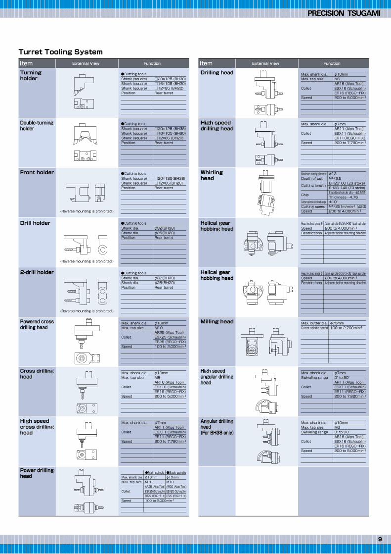
Turning holder
Double-turningholder
Front holder
Drill holder
2-drill holder
Powered crossdrilling head
Cross drillinghead
High speed cross drillinghead
Power drillinghead
Drilling head
High speed drilling head
Whirling head
Helical gear hobbing head
Helical gear hobbing head
Milling head
High speed angular drilling head
Angular drillinghead(For BH38 only)
Item External View Function Item External View Function
外 観
(Reverse mounting is prohibited.)
(Reverse mounting is prohibited.)
(Reverse mounting is prohibited.)
Turret Tooling System
□20×125 (BH38)□16×105 (BH20)□12×85 (BH20)Rear turret
Shank (square)Shank (square)Shank (square)Position
●Cutting tools
□20×125 (BH38)□16×105 (BH20)□12×85 (BH20)Rear turret
Shank (square)Shank (square)Shank (square)Position
●Cutting tools
□20×125(BH38)□12×85(BH20)Rear turret
Shank (square)Shank (square)Position
●Cutting tools
φ32(BH38)φ25(BH20)Rear turret
Shank dia.Shank dia.Position
●Cutting tools
φ32(BH38)φ25(BH20)Rear turret
Shank dia.Shank dia.Position
φ16mmM10AR25 (Alps Tool)ESX25 (Schaublin)ER25 (REGO-FIX)100 to 2,000min-1
Max. shank dia.Max. tap size
Collet
Speed
φ10mmM8AR16 (Alps Tool)ESX16 (Schaublin)ER16 (REGO-FIX)200 to 5,000min-1
Max. shank dia.Max. tap size
Collet
Speed
φ10mmM6AR16 (Alps Tool)ESX16 (Schaublin)ER16 (REGO-FIX)200 to 6,000min-1
Max. shank dia.Max. tap size
Collet
Speed
φ7mm0° to 90°AR11 (Alps Tool)ESX11 (Schaublin)ER11 (REGO-FIX)200 to 7,820min-1
Max. shank dia.Swiveling range
Collet
Speed
φ10mmM60° to 90°AR16 (Alps Tool)ESX16 (Schaublin)ER16 (REGO-FIX)200 to 5,000min-1
Max. shank dia.Max. tap sizeSwiveling range
Collet
Speed
φ7mmAR11 (Alps Tool)ESX11 (Schaublin)ER11(REGO-FIX)200 to 7,790min-1
Max. shank dia.
Collet
Speed
φ13MAX2.5BH20: 60 (Z3 stoke)BH38: 140 (Z3 stoke)Inscribed circle dia.…φ9.525Thickness…4.76±10°MAX251m/min-1 (φ20)200 to 4,000min-1
Maximum turning diameterDepth of cut
Cutting length
Chip
Cutter spindle inclined angleCutting speedSpeed
(Main spindle) 5°≦ θ ≦-30° (back spindle)200 to 4,000min-1Adjacent holder mounting disabled
Head inclined angle θSpeedRestrictions
(Main spindle) 5°≦ θ ≦-30° (back spindle)200 to 4,000min-1Adjacent holder mounting disabled
Head inclined angle θSpeedRestrictions
φ75mm100 to 2,700min-1
Max. cutter dia.Cutter spindle speed
φ7mmAR11 (Alps Tool)ESX11 (Schaublin)ER11 (REGO-FIX)200 to 7,790min-1
Max. shank dia.
Collet
Speed
●Main spindleφ16mmM10AR25 (Alps Tool)ESX25 (Schaublin)ER25 (REGO-F1X)100 to 2,000min-1
●Back spindleφ13mmM10AR20 (Alps Tool)ESX20 (Schaublin)ER20 (REGO-F1X)
Max. shank dia.Max. tap size
Collet
Speed
●Cutting tools
Even with multi-path control, multi-axis control, or complex-shaped parts, a program with the optimal tooling and the shortest cycle time can be created.Tsugami's machining know-how (machining processes, machining conditions, etc.) and the highest priority allocated to the matching of the machine hardware and software results in a system that enables novice programmers to create standardized, high quality programs, even for complex products that demand accurate results.
Optimized tooling with the help of a BH automatic programming system (optional)
■Create NC programs in a short period of time. No complicated entry is required.Create processes and NC programs automatically by simply inputting geometrical data and tool data. The interactive system helps you create programs easily and quickly.
■Simple operationsGeometrical data can be configured using a building block method (no acquisition of CAD skills required), and in addition, only minimal tool data entry is required.
■Automatic calculation of cycle timeThe cutting time and idle time are calculated automatically, which are helpful for the user to further shorten the cycle time.*The calculated cycle time is a reference value.
■3D simulation for operation checksThe 3D simulation function enables the user to check the operations from any angle.
■Interference check functionIt is possible to check the created/edited NC program for interference.
Many optional NC features on conventional model are provided as standard.
Name Specifications
The cycle time is calculated automatically, and cutting time/idle time as well as process time for each path system can be displayed.
The interference check function generates NC programs that have an optimal tool path free from interference.
Using the 3D simulation function, main spindle and back spindle machining operations can be checked from any angle.
Tool definition as like an actual mechanical setting, inputting tool type, tool width, drill dia., setting position, etc. for each tool.
No CAD operation required for work shape definition.By building up simple shapes (building block method), geometry can be created with ease in a drastically shortened time.Even a novice can quickly learn the input method.
Step 1: Tool definition Step 2: Work shape definition
NC program Cycle time
3D simulation
98
Applicable models
OS
Computer
BH20/BH20Z/BH38
WindowsⓇ2000 WindowsⓇXP(with Internet Explorer 4.0 or above and OpenGL library installed)
PC/AT compatibles (DOS/V machines)
CPU Intel CeleronⓇ 2.0 GHz or more
Chasing function
Continuous thread cutting
Manual pulse generator
Memory card input/output interface
RS232C input/output interface
Background editing
Run time/parts number display
Custom macro
Constant surface speed control
Spindle synchronous control
Tool geometry / wear offset
Programmable data input
Chamfering and corner R
Standard
Standard
Standard
Standard
Optional
Standard
Standard
Standard
Standard
Standard
Standard
Standard
Standard
Standard
Standard
Optional
Optional
Standard
Standard
Standard
Standard
Optional
Optional
Standard
Standard
Optional
Multiple repetitive cycle
Expanded program editing
Polar coordinate interpolation
Cylindrical interpolation
Direct drawing dimension input
Inch/metric conversion
Canned cycle for drilling
Rigid tap (main spindle, back spindle)
Rotary tool rigid tap (for tool on the turret)
Rotary tool rigid tap (for cross drill on the tool post)
Cut-off detection (differential)
Spindle speed fluctuation detection
Abnormal load detection
Name NameBH20/BH38 BH20/BH38
Work catcher (including work conveyor)
Work front discharge
Work rear discharge
Chip conveyor
Automatic fire extinguisher
Oil mist collector
High-pressure pump (750 W)
Drilling head
2-spindle cross drilling head (BH38 only)
Angular drilling head
Helical hobbing head (1)
Milling head
Machine Options
Turning holder
Double-turningholder
Front holder
Drill holder
2-drill holder
Powered crossdrilling head
Cross drillinghead
High speed cross drillinghead
Power drillinghead
Drilling head
High speed drilling head
Whirling head
Helical gear hobbing head
Helical gear hobbing head
Milling head
High speed angular drilling head
Angular drillinghead(For BH38 only)
Item External View Function Item External View Function
外 観
(Reverse mounting is prohibited.)
(Reverse mounting is prohibited.)
(Reverse mounting is prohibited.)
Turret Tooling System
□20×125 (BH38)□16×105 (BH20)□12×85 (BH20)Rear turret
Shank (square)Shank (square)Shank (square)Position
●Cutting tools
□20×125 (BH38)□16×105 (BH20)□12×85 (BH20)Rear turret
Shank (square)Shank (square)Shank (square)Position
●Cutting tools
□20×125(BH38)□12×85(BH20)Rear turret
Shank (square)Shank (square)Position
●Cutting tools
φ32(BH38)φ25(BH20)Rear turret
Shank dia.Shank dia.Position
●Cutting tools
φ32(BH38)φ25(BH20)Rear turret
Shank dia.Shank dia.Position
φ16mmM10AR25 (Alps Tool)ESX25 (Schaublin)ER25 (REGO-FIX)100 to 2,000min-1
Max. shank dia.Max. tap size
Collet
Speed
φ10mmM8AR16 (Alps Tool)ESX16 (Schaublin)ER16 (REGO-FIX)200 to 5,000min-1
Max. shank dia.Max. tap size
Collet
Speed
φ10mmM6AR16 (Alps Tool)ESX16 (Schaublin)ER16 (REGO-FIX)200 to 6,000min-1
Max. shank dia.Max. tap size
Collet
Speed
φ7mm0° to 90°AR11 (Alps Tool)ESX11 (Schaublin)ER11 (REGO-FIX)200 to 7,820min-1
Max. shank dia.Swiveling range
Collet
Speed
φ10mmM60° to 90°AR16 (Alps Tool)ESX16 (Schaublin)ER16 (REGO-FIX)200 to 5,000min-1
Max. shank dia.Max. tap sizeSwiveling range
Collet
Speed
φ7mmAR11 (Alps Tool)ESX11 (Schaublin)ER11(REGO-FIX)200 to 7,790min-1
Max. shank dia.
Collet
Speed
φ13MAX2.5BH20: 60 (Z3 stoke)BH38: 140 (Z3 stoke)Inscribed circle dia.…φ9.525Thickness…4.76±10°MAX251m/min-1 (φ20)200 to 4,000min-1
Maximum turning diameterDepth of cut
Cutting length
Chip
Cutter spindle inclined angleCutting speedSpeed
(Main spindle) 5°≦ θ ≦-30° (back spindle)200 to 4,000min-1Adjacent holder mounting disabled
Head inclined angle θSpeedRestrictions
(Main spindle) 5°≦ θ ≦-30° (back spindle)200 to 4,000min-1Adjacent holder mounting disabled
Head inclined angle θSpeedRestrictions
φ75mm100 to 2,700min-1
Max. cutter dia.Cutter spindle speed
φ7mmAR11 (Alps Tool)ESX11 (Schaublin)ER11 (REGO-FIX)200 to 7,790min-1
Max. shank dia.
Collet
Speed
●Main spindleφ16mmM10AR25 (Alps Tool)ESX25 (Schaublin)ER25 (REGO-F1X)100 to 2,000min-1
●Back spindleφ13mmM10AR20 (Alps Tool)ESX20 (Schaublin)ER20 (REGO-F1X)
Max. shank dia.Max. tap size
Collet
Speed
●Cutting tools

1110
Machine specifications (Standard)
Item Specification
NC Specifications (Standard)
FANUC 31i-BX1, Y1, Z1, X2, Z2, X3, Y3, Z3
0.001 mm (X1, X2, X3 axes in diameter)X1, X2, X3 axes: 0.0005 mm, other: 0.001 mm
±8 digitsLinear/Circular
1 to 6,000 mm/min0 to 150% in 10% increments
G04 0 to 99999.999X, Y, Z: absolute, U, V, W: incremental
±6 digitsSum of all paths: 200 pairs
10.4" color LCDSum of all paths: 256 kbytes (equivalent to 640 m tape length)
500M5 digitsS5 digitsT4 digits
NC unitAxis namesLeast input incrementLeast command incrementMaximum programmable dimensionInterpolation methodCutting feedrateFeedrate overrideDwellABS/INC commandTool offset valueTool offsets pairsLCD/MDITape storage sizeNumber of registerable programsAuxiliary functionsSpindle functionTool function
BH20/BH20Z
BH38
Tooling zone
54□
200 to 335
(Stroke=135)
φ38
50 50
Stroke=100
20 Stroke=300
12
94Max. machining length=250
220
230
20 50
3 16
21
68 (50 to 185)Stroke=13521
135
250
113
4747 29 to 84
(Stroke=55) 30
φ10
453636
Stroke=385
φ10
MAX150
85
57
Stroke=264
φ82
3636 5
□12
44
35.16
46.84 30
30
30
10 216
Stroke=226
35 35
Stroke=70
29
-2 to 29
(Stroke=31)
2
230230
193
198 to 308(Stroke=110)
164(Direct-drive rotary GB)
220
65
Stroke=285
81.5
37.5
37.5
146
113
※51 to 111Stroke=60
4-φ25
180
(81.5)
(standard GB type)
2Max. machining length 45
Collet chuck end face
332
13 to 273Stroke=260
334
Reference tool positionDirect-drive rotary GB (optional)
Guide-bushing-less unit (optional) ※ Z3 axis (BH20Z only)
Max. main spindle standby position
Max. machining length 170
Max. machining length 80
Reference tool position
Item BH20 BH20Z BH38
Machining range,machining capacity
Machine
Motors
Power sourceand other
Working barstock diameter
Max. machining length
Main spindle
Back spindle
Front tool post
Turret
φ3 to φ20 mm80 mm (Carrier type rotary GB)
170 mm (Direct-drive rotary GB) OP45 mm (GB-less type) OP
φ10 mmM8
φ20 mmφ10 mmM8
φ8 mmM6
φ10 mmM8
200 to 10,000 min-1
200 to 12,000 min-1
200 to 8,000 min-1
C axis
434
12 mm × 12 mm × 85 mm12 mm × 12 mm × 85 mm
12 m/min
20 m/min24 m/min
2.2/3.7 kW2.2/3.7 kW
4,500 kg30 KVA
2,480 x 1,585 x 1,733
200 to 8,000 min-1
C axis (optional)12 stations
-
7 axes
18 m/min
8 axes
Y3X1, Y1, X2, X3
Z1, Z2, Z3
12 m/min20 m/min
24 m/min
1.0 kW1.4 kW
0.39/0.62 kW (50/60Hz)3 W
0.5 MPa or more100 NL/min
φ8 to φ38.1 mm
250 mm
φ16 mmM14
φ38 mmφ16 mmM12
φ10 mmM6
φ16 mmM10
200 to 5,000 min-1
200 to 7,000 min-1
200 to 5,000 min-1 (Optional)
5°
52 (Optional)
320 mm × 20 mm × 125 mm16 mm × 16 mm × 125 mm
8 axes7.5/11 kW3.7/5.5 kW
5,800 kg45 KVA
2,730 x 1,790 x 1,700
Max. drilling diameterMax. tapping sizeMax. barstock diameterMax. drilling diameterMax. tapping size
Turret
Front tool post
Back tool postTurretFront tool postX1, Y3Z3X3Y1, Z1, X2, Z2
TurningCross drill
Max. cross drilling diameterMax. cross tapping sizeMax. rotary tool drilling diameterMax. rotary tool tapping size
Main spindle speedBack spindle speedCross drill speed on front tool postRotary tool speed on turretMain spindle indexingBack spindle indexing
Total toolstoragecapacity
Tool size
Rapidtraverserate
Controlled axesMain spindleBack spindleCross drill on front tool postRotary tool speed on turretCoolant pumpLubricating oil pumpNet weightPower source requirementCompressed air requirementAir discharge rateWidth x depth x height
3-spindle crossdrilling head (Standard)
2-spindle cross drilling head (AR16×2) (Optional)3-spindle cross drilling head (AR11×3) (Optional)
External View
CAT.NO.E112524.JUN.3T(H)
External View
12-20, TOMIZAWA-CHO, NIHONBASHI, CHUO-KU, TOKYO 103-0006, JAPANPhone : 03-3808-1172Facsimile : 03-3808-1175
1,733
1,000 (Center height)
1,910(560)
570
3,040
520
(160)
700
185
425
(20)
1,585
2,480
1,405
CNC Precision Automatic Lathe
Sliding headstock type automatic lathe that encompasses the entire process12-station turret + Gang type tool post + Back spindle
BH20/BH20Z
BH38
Export permission by the Japanese Government may be required for exportingour products in accordance with the Foreign Exchange and Foreign Trade Law.Please contact our sales office before exporting our products. The specifications of this catalogue are subject to change without prior notice.
980810
1,000 1,700
1,130 1,2002,330 400
2,730
610
810
1,790
3,393
(100)(563)