TRAUB TNL20 - Sliding / fixed headstock automatic lathe // EN · 2017-09-15 · 2 Sliding/fixed...
20
TNL20 Sliding / fixed headstock automatic lathe for precise and economical machining better.parts.faster.
Transcript of TRAUB TNL20 - Sliding / fixed headstock automatic lathe // EN · 2017-09-15 · 2 Sliding/fixed...
TNL20Sliding / fixed headstock automatic lathe for precise and economical machining
better.parts.faster.
2
Sliding/fixed headstock automatic lathe TNL20
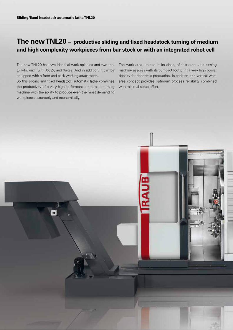
The new TNL20 – productive sliding and fixed headstock turning of medium and high complexity workpieces from bar stock or with an integrated robot cell
The new TNL20 has two identical work spindles and two tool
turrets, each with X-, Z-, and Y-axes. And in addition, it can be
equipped with a front and back working attachment.
So this sliding and fixed headstock automatic lathe combines
the productivity of a very high-performance automatic turning
machine with the ability to produce even the most demanding
workpieces accurately and economically.
The work area, unique in its class, of this automatic turning
machine assures with its compact foot print a very high power
density for economic production. In addition, the vertical work
area concept provides optimum process reliability combined
with minimal setup effort.
3
• Very fast and energy-
efficient dog clamping
on the main spindle and
counter spindle
• Generous and process-
reliable work area
• Hydraulic-free machine:
No heat input caused by a
hydraulic system – energy
saving inclusive
The machine design
• Bar capacity up to ø 20 mm
• Up to three tool carriers
and one back working
attachment, each with Y-axis
• Simultaneous machining
with two, three or four tools
• High tool pool for set-
up-friendly production
• Short tool changing times
by means of CNC indexing
axis in the tool turrets
and in the front working
attachment
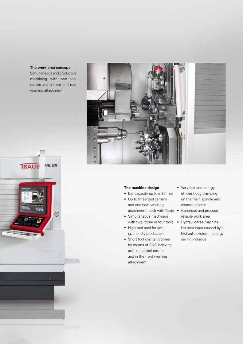
The work area concept
Simultaneous and productive
machining with two tool
turrets and a front and rear
working attachment.

4
Sliding/fixed headstock automatic lathe TNL20
TNL20-9 / TNL20-9B – simultaneous and precise manufacturing with up to three tools
The machine’s crucial productivity advantage is the result of its
extraordinarily high dynamics. The newly developed machine
bed from gray cast iron forms the basis for utmost vibration
dampening properties. And the high rigidity and thermal
stability ensure optimum workpiece quality.
The machine concept of the TNL20 has been systematically
matched to the daily requirements of the user.
So the kinematics of the machine allows effective and simulta-
neous machining with two or three tools.
The generous and vertically arranged work area provides for the
necessary degrees of freedom, as well as for very high process
reliability.
Kinematics TNL20-9
Kinematics TNL20-9B
Spindle / shaft
Dimensions, mm Ø14 x 100
Material 1.4305
Cycle time 93 s
Implantat
Dimensions, mm Ø4 x 15
Material Titan
Cycle time 241 s
Anchoring sleeve
Dimensions, mm Ø16 x 30
Material 1.4305
Cycle time 230 s

5

6
Sliding/fixed headstock automatic lathe TNL20
TNL20-11 with additional front working attachment – precise and even more efficient production with four tools simultaneously
Control slide valve
Dimensions, mm Ø18 x 120
Material 1.4305
Cycle time 163 s
Aluminum housing
Dimensions, mm Ø18 x 26
Material Al
Cycle time 227 s
Drive shaft
Dimensions, mm Ø14 x 100
Material 1.4305
Cycle time 196 s
7
8
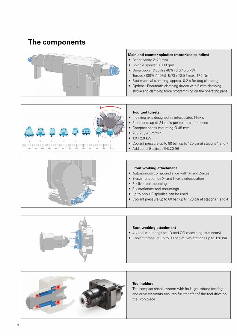
Main and counter spindles (motorized spindles)• Bar capacity Ø 20 mm• Spindle speed 10,000 rpm • Drive power (100% / 40%) 3.0 / 5.5 kW
Torque (100% / 40%) 5.73 / 10.5 / max. 17.2 Nm • Fast material clamping, approx. 0.2 s for dog clamping• Optional: Pneumatic clamping device with 6 mm clamping
stroke and clamping force programming on the operating panel
Tool holders The compact shank system with its large, robust bearings and drive elements ensures full transfer of the tool drive on the workpiece
Back working attachment• 4 x tool mountings for ID and OD machining (stationary) • Coolant pressure up to 80 bar, at two stations up to 120 bar
Front working attachment• Autonomous compound slide with X- and Z-axes• Y-axis function by X- and H-axis interpolation• 3 x live tool mountings• 3 x stationary tool mountings• up to two HF spindles can be used• Coolant pressure up to 80 bar, up to 120 bar at stations 1 and 4
The components
Two tool turrets• Indexing axis designed as interpolated H-axis• 8 stations, up to 24 tools per turret can be used• Compact shank mounting Ø 45 mm• 20 / 20 / 40 m/min• 1.0 / 2.0 kW• Coolant pressure up to 80 bar, up to 120 bar at stations 1 and 7• Additional B axis at TNL20-9B1200 1100 1000 900 800 700 600 500 400 300 200 100 0 mm
7 6 5 4 3 2 18

9
10
Sliding/fixed headstock automatic lathe TNL20
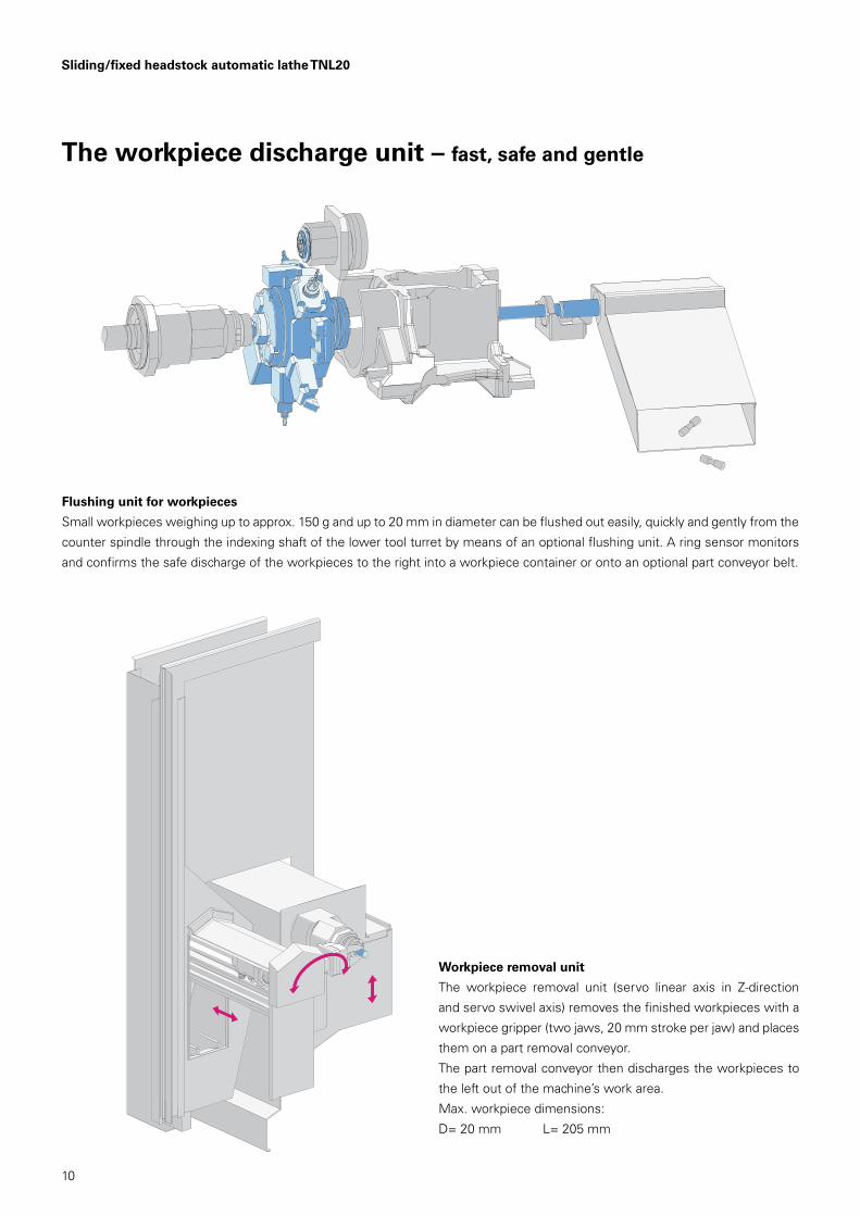
The workpiece discharge unit – fast, safe and gentle
Flushing unit for workpieces
Small workpieces weighing up to approx. 150 g and up to 20 mm in diameter can be flushed out easily, quickly and gently from the
counter spindle through the indexing shaft of the lower tool turret by means of an optional flushing unit. A ring sensor monitors
and confirms the safe discharge of the workpieces to the right into a workpiece container or onto an optional part conveyor belt.
Workpiece removal unit
The workpiece removal unit (servo linear axis in Z-direction
and servo swivel axis) removes the finished workpieces with a
workpiece gripper (two jaws, 20 mm stroke per jaw) and places
them on a part removal conveyor.
The part removal conveyor then discharges the workpieces to
the left out of the machine’s work area.
Max. workpiece dimensions:
D= 20 mm L= 205 mm
11

12
Integrated robot cellIntelligent automation – even more flexibility and efficiency
Simply good handling of blanks and finished parts
• Space-saving vertical storage with up to 14 pallets stacked up
• Pallet size 400x300 mm
• Minimal pallet height 25.4 mm
• Pallets with blanks are loaded at the top, pallets with
finished parts are removed at the bottom – at any time
without interrupting production
• The pallet is pulled in and out by the robot
• Easy macro-programming
Using more potentials
The space above the vertical storage can be used easily for sub-
sequent processes such as cleaning, measuring, deburring, etc.
The preparation for incorporating a fully automatic 3D
measuring cell is already provided as standard
• Closed-loop process control is possible
• SPC parts output and NOK parts output is provided
Ready to Go
• 6-axis robot for 6 kg payload with integrated gripper control
• Double gripper included in the standard
• 14 pallets (without workpiece-specific inlays) are included in
the standard
• No separate installation and setup required
• Easy, in-house relocation
With the optional robotic cell, blanks and/or finished parts can be supplied and discharged quickly, safely and flexibly. The robot cell
is integrated ergonomically into the machine. It can be moved easily to the left during the setup process, allowing unobstructed
access to the work area of the machine. During production, the robot cell is fixed in front of the machine’s work area. The robot
then accesses the work area via the sliding guard of the machine, which opens automatically behind the robot cell.

13
14
index-traub.com/ixpanel
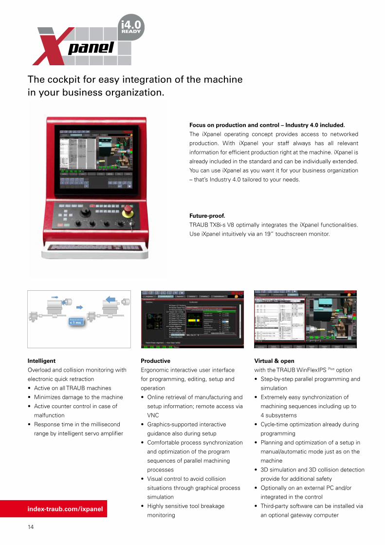
Focus on production and control – Industry 4.0 included.
The iXpanel operating concept provides access to networked
production. With iXpanel your staff always has all relevant
information for efficient production right at the machine. iXpanel is
already included in the standard and can be individually extended.
You can use iXpanel as you want it for your business organization
– that’s Industry 4.0 tailored to your needs.
Future-proof.
TRAUB TX8i-s V8 optimally integrates the iXpanel functionalities.
Use iXpanel intuitively via an 19” touchscreen monitor.
Productive
Ergonomic interactive user interface
for programming, editing, setup and
operation
• Online retrieval of manufacturing and
setup information; remote access via
VNC
• Graphics-supported interactive
guidance also during setup
• Comfortable process synchronization
and optimization of the program
sequences of parallel machining
processes
• Visual control to avoid collision
situations through graphical process
simulation
• Highly sensitive tool breakage
monitoring
Virtual & open
with the TRAUB WinFlexIPS Plus option
• Step-by-step parallel programming and
simulation
• Extremely easy synchronization of
machining sequences including up to
4 subsystems
• Cycle-time optimization already during
programming
• Planning and optimization of a setup in
manual/automatic mode just as on the
machine
• 3D simulation and 3D collision detection
provide for additional safety
• Optionally on an external PC and/or
integrated in the control
• Third-party software can be installed via
an optional gateway computer
The cockpit for easy integration of the machine in your business organization.
Intelligent
Overload and collision monitoring with
electronic quick retraction
• Active on all TRAUB machines
• Minimizes damage to the machine
• Active counter control in case of
malfunction
• Response time in the millisecond
range by intelligent servo amplifier
Response time
< 1 ms

15
NE
TW
OR
K
SE
RV
ER
AP
PLI
CA
TIO
N
CUSTOMER
STANDARD included as standard
Order documents
Customer data Drawings Setup sheet
Notes Information center
Ind
ust
ry 4
.0 fe
atu
res
Technology computer
Programming help
User management
+ many more standard features
Browser
Remote access
OPTION
• WinFlexIPS• WinFlexIPS Plus
• Custom applications
19" TOUCHSCREEN

16
Sliding/fixed headstock automatic lathe TNL20
Work area TNL20-9
205
80
Turning with guide bush
Turning without guide bush
Tool turret 2 Revolver 2
Revolver 1
Tool turret 1
HSP
Rear end machining unit
Rückapparat
CSP
CSP
155
120
120
254
16
525
258235.5
MSP
66
90°
25.4
25.4120
25.4
25.4120
105°
10°
205
567,5
max. 249
155
80
165
120
Tool turret 1
Turning with guide bush
Turning without guide bush
Work area TNL20-9B
* Dimension without robot cell** Dimension with robot cell
Installation Chart
2954183
2247
**
2185
**15
23*
2200
*
1242 2280

17
Technical data TNL20-9 TNL20-9B
Headstock
Max. bar capacity mm 20
Max. Z-travel Sliding headstock machine/fixed headstock machine mm 1) 205 / 80
Max. speed rpm 10,000
Power at 100%/40% kW 3.0 / 5.5
Torque at 100%/40% Nm 5.73 / 10.5 / max. 17.2
C-axis resolution Deg. 0.001
Max. rapid traverse rate Z m/min 20
Upper tool turret
Tool mountings Number 8
Live tools Number 8
Max. speed rpm 12,000 8,000
Mounting ø mm 45
Power at 100%/40% kW 1.0 / 2.0
Turning tool cross-section mm 16x16 / 20x20
Slide travel X mm 120 165
Slide travel Y mm ±25.4
Slide travel Z mm 254 567.5
Rapid traverse rate X / Y / Z m/min 20 / 20 / 40
Swivel angle B axis Deg. 105
Lower tool turret
Tool mountings Number 8
Live tools Number 8
Max. speed rpm 12,000
Mounting ø mm 45
Power at 100%/40% kW 1.0 / 2.0
Turning tool cross-section mm 16x16 / 20x20
Slide travel X mm 120
Slide travel Y mm ±25.4
Slide travel Z mm 155
Rapid traverse rate X / Y / Z m/min 20 / 20 / 40
Back working attachment
Tool mountings Number 4
Slide travel X / Y / Z mm 120 / ±25.4 / 155
Mounting ø mm 25
Counter spindle
Max. spindle capacity mm 20
Max. speed rpm 10,000
Power at 100%/40% kW 3.0 / 5.5
Torque at 100%/40% Nm 5.73 / 10.5 / max. 17.2
Slide travel X mm 235.5
Slide travel Z mm 258
C-axis resolution Deg. 0.001
Rapid traverse rate X / Z m/min 20 / 40
Cooling lubricant unit (basic unit)Pump pressure bar 3 / 8
Tank capacity l 250
Pump capacity 3 / 8 bar l/min 80 / 120
Filter fineness µm 200
Machine dimensions
Length x width x height mm see installation chart *
Weight kg 5,000 *
Connected power kW 40 (47 kVA)
*depending on equipment
1) The headstock stroke depends on the clamping device being used

18
Work area TNL20-11
Sliding/fixed headstock automatic lathe TNL20
300
140
108,49°
2,91°
250
205
80
Turning with guide bush
Turning without guide bush
205
80
Turning with guide bush
Turning without guide bush258
210,5
Tool turret 2 Tool turret 2
Tool turret 1Tool turret 1
Rear end machining unit Rear end machining unit
CSP
GSP
Front working attachment Front working attachment
525
155120
120
205
205 105
51MSP MSP
205
80
Turning with guide bush
Turning without guide bush258
210.5
Tool turret 2 Revolver 2
Revolver 1Tool turret 1
HSP
Rear end machining unitRückapparat
GSP
CSPFHGB
Front working attachment
Frontapparat
525
155120
120
205
205 105
51MSP
66
90°
25.4
25.4120
25.4
25.4120
19
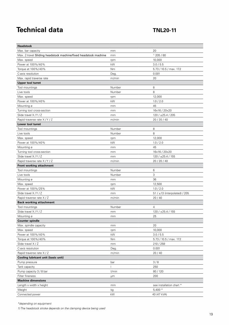
Technical data TNL20-11
Headstock
Max. bar capacity mm 20
Max. Z-travel Sliding headstock machine/fixed headstock machine mm 1) 205 / 80
Max. speed rpm 10,000
Power at 100%/40% kW 3.0 / 5.5
Torque at 100%/40% Nm 5.73 / 10.5 / max. 17.2
C-axis resolution Deg. 0.001
Max. rapid traverse rate m/min 20
Upper tool turret
Tool mountings Number 8
Live tools Number 8
Max. speed rpm 12,000
Power at 100%/40% kW 1.0 / 2.0
Mounting ø mm 45
Turning tool cross-section mm 16x16 / 20x20
Slide travel X / Y / Z mm 120 / ±25.4 / 205
Rapid traverse rate X / Y / Z m/min 20 / 20 / 40
Lower tool turret
Tool mountings Number 8
Live tools Number 8
Max. speed rpm 12,000
Power at 100%/40% kW 1.0 / 2.0
Mounting ø mm 45
Turning tool cross-section mm 16x16 / 20x20
Slide travel X / Y / Z mm 120 / ±25.4 / 155
Rapid traverse rate X / Y / Z m/min 20 / 20 / 40
Front working attachment
Tool mountings Number 6
Live tools Number 3
Mounting ø mm 36
Max. speed rpm 12,500
Power at 100%/ 25% kW 1.0 / 2.0
Slide travel X / Y / Z mm 51 / ±13 (interpolated) / 205
Rapid traverse rate X / Z m/min 20 / 40
Back working attachment
Tool mountings Number 4
Slide travel X / Y / Z mm 120 / ±25.4 / 155
Mounting ø mm 25
Counter spindle
Max. spindle capacity mm 20
Max. speed rpm 10,000
Power at 100%/40% kW 3.0 / 5.5
Torque at 100%/40% Nm 5.73 / 10.5 / max. 17.2
Slide travel X / Z mm 210 / 258
C-axis resolution Deg. 0.001
Rapid traverse rate X / Z m/min 20 / 40
Cooling lubricant unit (basic unit)
Pump pressure bar 3 / 8
Tank capacity l 250
Pump capacity 3 / 8 bar l/min 80 / 120
Filter fineness µm 200
Machine dimensions
Length x width x height mm see installation chart *
Weight kg 5,400 *
Connected power kW 40 (47 kVA)
*depending on equipment
1) The headstock stroke depends on the clamping device being used
09.1
7 –
862/
1 P
rinte
d in
Ger
man
y Te
chni
cal d
ata
subj
ect
to c
hang
e
better.parts.faster.
INDEX-Werke GmbH & Co. KGHahn & Tessky Plochinger Straße 9273730 Esslingen
Phone +49 711 3191-0 Fax +49 711 3191-587 [email protected]
BRAZIL // SorocabaINDEX Tornos Automaticos Ind. e Com. Ltda.Rua Joaquim Machado 250 18087-280 Sorocaba - SPPhone +55 15 2102 6017 [email protected] br.index-traub.com
CHINA // ShanghaiINDEX Trading (Shanghai) Co., Ltd. No.526, Fute East 3rd RoadShanghai 200131 Phone +86 21 54176637 [email protected] www.index-traub.cn
CHINA // DalianINDEX DALIAN Machine Tool Ltd. 17 Changxin RoadDalian 116600 Phone +86 411 8761 9788 [email protected]
DENMARK // LangeskovINDEX TRAUB DanmarkHavretoften 15550 LangeskovPhone +45 30681790 [email protected]
GERMANY // EsslingenINDEX-Werke GmbH & Co. KG Hahn & Tessky Plochinger Straße 9273730 Esslingen Phone +49 711 3191-0 [email protected]
GERMANY // DeizisauINDEX-Werke GmbH & Co. KG Hahn & Tessky Plochinger Straße 4473779 Deizisau Phone +49 711 3191-0 [email protected]
GERMANY // ReichenbachINDEX-Werke GmbH & Co. KG Hahn & Tessky Hauffstraße 4 73262 Reichenbach Phone +49 7153 502-0 [email protected]
FINLAND // HelsinkiINDEX TRAUB FinlandHernepellontie 2700710 HelsinkiPhone +35 8 [email protected]
FRANCE // ParisINDEX France Sarl1A, Avenue du Québec / Z.A. de Courtabœuf91941 Les Ulis CedexPhone +33 1 69187676 [email protected] www.index-france.fr
FRANCE // BonnevilleINDEX France Sarl399, Av. de La Roche Parnale74130 Bonneville CedexPhone +33 4 50256534 [email protected]
NORWAY // OsloINDEX TRAUB NorgePostbox 28420204 OsloPhone +46 8 505 979 00 [email protected]
SWEDEN // StockholmINDEX TRAUB Nordic ABFagerstagatan 216308 SpångaPhone +46 8 505 979 00 [email protected] www.index-traub.se
SLOVAKIA // MalackyGematech s.r.o. Vinohrádok 5359 Malacky 901 01Phone +34 654 [email protected] www.index-traub.com
UNITED STATES // NoblesvilleINDEX Corporation14700 North Point BoulevardNoblesville, IN 46060Phone +1 317 770 6300 [email protected]