Fixed Headstock Type CNC Automatic Lathe - Yamazen
12
Fixed Headstock Type CNC Automatic Lathe
Transcript of Fixed Headstock Type CNC Automatic Lathe - Yamazen
Fixed Headstock Type CNC Automatic Lathe

The BNA series packs sophisticated functions and high accuracy into a space-saving compact body. The BNA series aims to set the new standard for machines for cutting bar stock, based on the concept of “space savings and sophisticated functions”. The BNA42S enables back machining with its 2 spindles and 1 turret and combines a high level of basic performance with convenience of use. The BNA42DHY achieves further shortening of cycle times by adding a compact sub-turret to provide superimposition machining and other forms of simultaneous machining. The BNA series offers high performance in compact space, round-the-clock stability and accuracy; and ease of use for fast set-ups and quick changeovers.


4
DHY

5
In addition to its 5-inch power chuck on the front spindle, the back spindle can also mount a 4-inch power chuck for flexible accommodation of forged parts.
Simultaneous front/back machining
X1Y1
Turret HD2
X2
Z2
Turret HD1
SP2
SP1
Power Chuck on Back Spindle
Basic Construction and Axis ConfigurationZ1
Y-axis Function and Sub-turret
The combination of the Y-axis function incorporated in the main turret (HD1) and the compact 6 -station sub-turret (HD2) can achieve further reductions in machining t ime through over lap processing and other forms of machining performed simultaneously on the main and sub spindles.
High-rigidity Scraped Slideways Support Powerful CuttingHigh-rigidity scraped slideways are used on all axes except for X axis of SP2. These slideways with face contacts have exceptional rigidity and damping characteristics, achieve powerful cutting, and help to prolong the lives of cutting tools.
6
S

7
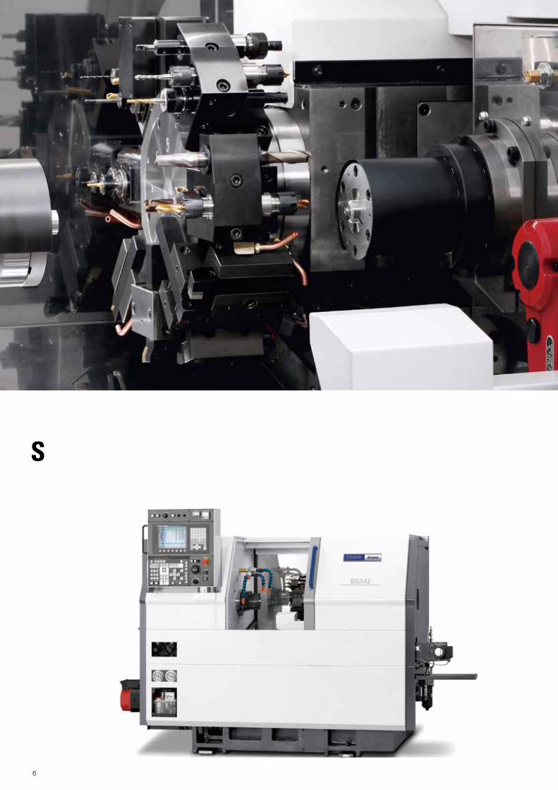
The S model delivers increased versatility with the provision of a sub-spindle for pick-off and back machining. Multiple tool holders enable the use of many tools for unrivalled flexibility in a bar turning machine of this compact size.All BNA models incorporate the latest control technology for reduced non-cutting time and improved productivity.
Back machining using tools installed in a triple sleeve holder
Sub-spindle Enables Complete Machining
X
B
Turret HD1
SP2
SP1
Z
The 8 station turret with half indexing in combination with multi tool holders helps to standardize set-ups and enable fast changeover to a different workpiece.With double, triple and even quad tool holders you are assured of sufficient tool positions even for complex workpieces.
Extensive Tool Range
Basic Construction and Axis Configuration
Stable, accurate and strong The machine bed has a platform structure with traditional square, hand-scraped slidways for assured accuracy and long tool life.The unit mounting faces are not distorted by the effects of heat, and even if the units are subject to thermal expansion they are al l d isplaced in the same direction (perpendicular to their mounting faces), minimizing relative deviations between the workpiece and cutting tools.

8
Substantial Reduction in Non-cutting Time
Miyano’s unique control system cuts non-cutting time by 27% (compared to previous model), achieving a 13% reduction in terms of total cycle time.
Workpiece used for data measurement
Options
Part catcherCatches workpieces without damaging them and transfers them to the part conveyor.
Part conveyorTranspor ts workpieces received from the par t catcher to outside the machine.
Program handwheel (DHY)
Easy prove-out is assured using the handwheel for program prove-out.
Cutting time Non-cutting timeConventional
machine
BNA-S
147 sec.
127.5 sec.
75.5 sec. 71.5 sec.
27% reduction (non-cutting time)
13% reduction (Total cycle time)
75.5 sec. 52 sec.
Chip conveyorEjects chips smoothly. Various types are available to suit the application.
Bar feederA range of barfeeders is available for short or long bars.
9
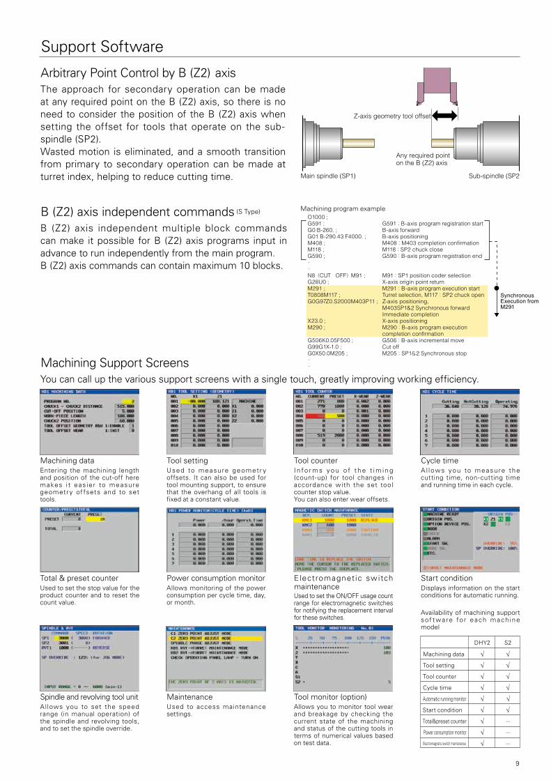
Support Software
Arbitrary Point Control by B (Z2) axisThe approach for secondary operation can be made at any required point on the B (Z2) axis, so there is no need to consider the position of the B (Z2) axis when setting the offset for tools that operate on the sub-spindle (SP2).Wasted motion is eliminated, and a smooth transition from primary to secondary operation can be made at turret index, helping to reduce cutting time.
Machining Support ScreensYou can call up the various support screens with a single touch, greatly improving working efficiency.
Machining dataEntering the machining length and position of the cut-off here makes i t eas ier to measure geometry of fsets and to set tools.
Tool settingUsed to measure geometr y offsets. It can also be used for tool mounting support, to ensure that the overhang of all tools is fixed at a constant value.
Tool counterI n fo r m s y o u o f t h e t i m i n g (count-up) for tool changes in accordance with the set tool counter stop value.You can also enter wear offsets.
Cycle timeA l lows you to measure the cutting time, non-cutting time and running time in each cycle.
Start conditionDisplays information on the start conditions for automatic running.
Spindle and revolving tool unitAllows you to set the speed range (in manual operation) of the spindle and revolving tools, and to set the spindle override.
MaintenanceUsed to access maintenance settings.
Tool monitor (option)Allows you to monitor tool wear and breakage by checking the current state of the machining and status of the cutting tools in terms of numerical values based on test data.
Total & preset counterUsed to set the stop value for the product counter and to reset the count value.
Power consumption monitorAllows monitoring of the power consumption per cycle time, day, or month.
Electromagnetic switch maintenanceUsed to set the ON/OFF usage count range for electromagnetic switches for notifying the replacement interval for these switches.
DHY2 S2
Machining data √ √
Tool setting √ √
Tool counter √ √
Cycle time √ √
Automatic running monitor √ √
Start condition √ √
Total&preset counter √ - - -
Power consumption monitor √ - - -
Electromagnetic switch maintenance √ - - -
Availability of machining support sof t ware fo r each mach ine model
Z-axis geometry tool offset
Sub-spindle (SP2)Main spindle (SP1)
Any required point on the B (Z2) axis
B (Z2) axis independent commands (S Type)
B (Z2) axis independent multiple block commands can make it possible for B (Z2) axis programs input in advance to run independently from the main program.B (Z2) axis commands can contain maximum 10 blocks.
O1000 ; G591 ; G591:B-axis program registration startG0 B-260. ; B-axis forwardG01 B-290.43 F4000. ; B-axis positioningM408 ; M408:M403 completion confirmationM118 ; M118:SP2 chuck closeG590 ; G590:B-axis program registration end・ ・ N8(CUT OFF)M91 ; M91:SP1 position coder selectionG28U0 ; X-axis origin point returnM291 ; M291:B-axis program execution startT0808M117 ; Turret selection, M117:SP2 chuck openG0G97Z0.S2000M403P11 ; Z-axis positioning, M403SP1&2 Synchronous forward Immediate completionX23.0 ; X-axis positioningM290 ; M290:B-axis program execution completion confirmationG506K0.05F500 ; G506:B-axis incremental moveG99G1X-1.0 ; Cut offG0X50.0M205 ; M205:SP1&2 Synchronous stop・ ・
SynchronousExecution fromM291
Machining program example

10
Triple sleeve holder25 mm Dia. (1”)
Double sleeve holder25 mm Dia. (1”)
Drill bush 20Max. Ø12
Drill holder
Round hole bush
Collet holder
Tapping colletCollet holder
Center drill
Center drill
Straight drill
Straight shank drill
Boring tool
Tap
Straight shank raemer
Doble turning holder20 mm Sq. (3/4”)
Turning holder‘S’20 mm Sq. (3/4”)
Cut off tool holder20×12 mm Sq.(3/4”×1/2”)
Turning tool
Z double spindle unit
Nut
Center drillChuck collet
Tapping collet Tap
End mill
Straight shank drill
Chuck collet
Tapping collet
X spindle unit
Z spindle unit
Nut
Tap
Center drill
End mill
Straight shank drill
Tap collet
Knee tool holder20 mm Sq. (3/4”)
Stopper plate
ZS spindle unit
Chuck collet
Doble turning holder‘S’20 mm Sq. (3/4”)
Turning holder20 mm Sq. (3/4”)
Stopper plate‘S’
Double sleeve holder‘A’25 mm Dia. (1”)
Combination holder20 mm Sq.(3/4”) 25 mm Dia.(1”)
Double sleeve holder‘D’25 mm Dia. (1”)
Cap A
8 Station turret
Pull out finger
Tooling system
DHY
S
Triple sleeve holder25 mm Dia. (1”)
Double sleeve holder25 mm Dia. (1”)
Drill bush 20Max. Ø12
Drill holder
Round hole bush
Collet holder
Tapping colletCollet holder
Center drill
Center drill
Straight drill
Straight shank drill
Boring tool
Tap
Straight shank reamer
Turning holder20 mm Sq. (3/4”)
Turning holder‘S’20 mm Sq. (3/4”)
Cut off tool holder20×12 mm Sq. (3/4”×1/2”)
Turning tool
Z Double Spindle unit
Nut
Center drillChuck collet
Tapping collet Tap
End mill
Straight shank drill
Chuck collet
Tapping collet
X Spindle unit
Z Spindle unit
Nut
Tap
Center drill
End mill
Straight shank drill
Tapping collet
Knee tool holder20 mm Sq. (3/4”)
Stopper plate
ZS Spindle unit
Chuck collet
Double turning holder‘S’20 mm Sq. (3/4”)
Turning holder20 mm Sq. (3/4”)
Stopper plate‘S’
Double sleeve holder‘A’25 mm Dia. (1”)
Plain holder & turning20 mm Sq. (3/4”)25 mm Dia. (1”)
HD18 Station turret
HD26 Station turret
Double sleeve holder‘D’25 mm Dia. (1”)
Cap A
Quad sleeve holder 25 mm Dia. (1”)
Double turning tool holder20 mm Sq. (3/4”)
Triple turning tool holder20 mm Sq. (3/4”)
X Double Spindle unit
Z Double Spindle unit
X Four Spindle unit
Z Four Spindle unit
Z Double Spindle unit
X Four Spindle unit
Pull out finger
Round hole bush Boring tool

11
External view
DHY
S
B Stroke 310
69
20
37 35
25 mm Dia.
35
44
44X
Str
oke
135
X1
stro
ke14
0
X2
stro
ke14
0
8st.
H20
0
8st.
H20
0
135
78
71.5
390 mm Dia. 59
Z stroke 235
Z1 Stroke
Z2 stroke 360
Y1 stroke 70
154
115
mm
Dia
.
135
mm
Dia
.
Collet chuck
5" Power chuck
417 148.5
52
85
56
12 mm Dia.
M8×1.25
zero
poi
nt
zero point
zero point
2nd zero point
Collet chuck
Collet chuck(H-S20)
Collet chuck(JPN34)
4-inch power chuck
Collet chuck
Collet chuck(H-S20)
Collet chuck(JPN34)
4-inch power chuck
zero point
zero
poi
nt
Tooling area
DHY
S
1,353493
1,454
1,12
0
1,60
0
1,69
5
570 1,200 235
2,350 185
1,900
1,02
0 1,48
0
1,66
0
2,150 1,290
400 430250
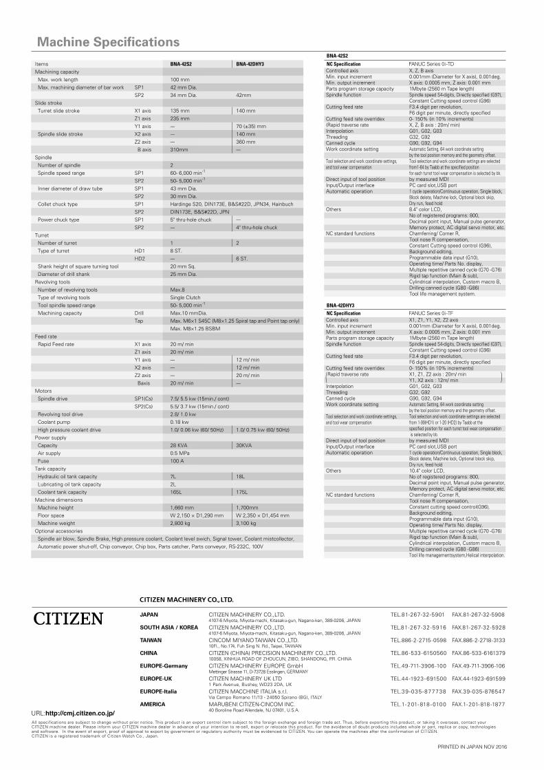
Machine SpecificationsNC Specification FANUC Series 0i-TDControlled axis X, Z, B axis Min. input increment 0.001mm (Diameter for X axis), 0.001deg.Min. output increment X axis: 0.0005 mm, Z axis: 0.001 mmParts program storage capacity 1Mbyte (2560 m Tape length) Spindle function Spindle speed S4-digits, Directly specified (G97), Constant Cutting speed control (G96)Cutting feed rate F3.4 digit per revolution, F6 digit per minute, directly specifiedCutting feed rate overridex 0- 150% (in 10% increments)(Rapid traverse rate X, Z, B axis : 20m/ min)Interpolation G01, G02, G03Threading G32, G92Canned cycle G90, G92, G94Work coordinate setting Automatic Setting, 64 work coordinate setting by the tool position memory and the geometry offset.Tool selection and work coordinate settings, Tool selection and work coordinate settings are selected and tool wear compensation from1-64 by Taabb at the specified position for each turret tool wear compensation is selected by bb.Direct input of tool position by measured MDIInput/Output interface PC card slot,USB portAutomatic operation 1 cycle operation/Continuous operation, Single block, Block delete, Machine lock, Optional block skip, Dry run, feed holdOthers 8.4" color LCD, No of registered programs: 800, Decimal point input, Manual pulse generator, Memory protect, AC digital servo motor, etc.NC standard functions Chamferring/ Corner R, Tool nose R compensation, Constant Cutting speed control (G96), Background editing, Programmable data input (G10), Operating time/ Parts No. display, Multiple repetitive canned cycle (G70 -G76) Rigid tap function (Main & sub), Cylindrical interpolation, Custom macro B, Drilling canned cycle (G80 -G86) Tool life management system.
NC Specification FANUC Series 0i-TFControlled axis X1, Z1, Y1, X2, Z2 axisMin. input increment 0.001mm (Diameter for X axis), 0.001deg.Min. output increment X axis: 0.0005 mm, Z axis: 0.001 mmParts program storage capacity 1Mbyte (2560 m Tape length) Spindle function Spindle speed S4-digits, Directly specified (G97), Constant Cutting speed control (G96)Cutting feed rate F3.4 digit per revolution, F6 digit per minute, directly specifiedCutting feed rate overridex 0- 150% (in 10% increments) Rapid traverse rate X1, Z1, Z2 axis : 20m/ min Y1, X2 axis : 12m/ minInterpolation G01, G02, G03Threading G32, G92Canned cycle G90, G92, G94Work coordinate setting Automatic Setting, 64 work coordinate setting by the tool position memory and the geometry offset.Tool selection and work coordinate settings, Tool selection and work coordinate settings are selected and tool wear compensation from 1-99(HD1) or 1-20 (HD2) by Taabb at the specified position for each turret tool wear compensation is selected by bb.Direct input of tool position by measured MDIInput/Output interface PC card slot,USB portAutomatic operation 1 cycle operation/Continuous operation, Single block, Block delete, Machine lock, Optional block skip, Dry run, feed holdOthers 10.4" color LCD, No of registered programs: 800, Decimal point input, Manual pulse generator, Memory protect, AC digital servo motor, etc.NC standard functions Chamferring/ Corner R, Tool nose R compensation, Constant cutting speed control(G96), Background editing, Programmable data input (G10), Operating time/ Parts No. display, Multiple repetitive canned cycle (G70 -G76) Rigid tap function (Main & sub), Cylindrical interpolation, Custom macro B, Drilling canned cycle (G80 -G86) Tool life managementsystem,Helical interpolation.
Items BNA-42S2 BNA-42DHY3Machining capacity Max. work length 100 mm Max. machining diameter of bar work SP1 42 mm Dia. SP2 34 mm Dia. 42mm Slide stroke Turret slide stroke X1 axis 135 mm 140 mm Z1 axis 235 mm Y1 axis --- 70 (±35) mm Spindle slide stroke X2 axis --- 140 mm Z2 axis --- 360 mm B axis 310mm ---Spindle Number of spindle 2 Spindle speed range SP1 60- 6,000 min-1
SP2 50- 5,000 min-1
Inner diameter of draw tube SP1 43 mm Dia. SP2 30 mm Dia. Collet chuck type SP1 Hardinge S20, DIN173E, B&S#22D, JPN34, Hainbuch SP2 DIN173E, B&S#22D, JPN Power chuck type SP1 5" thru-hole chuck --- SP2 --- 4" thru-hole chuckTurret Number of turret 1 2 Type of turret HD1 8 ST. HD2 --- 6 ST. Shank height of square turning tool 20 mm Sq. Diameter of drill shank 25 mm Dia.Revolving tools Number of revolving tools Max.8 Type of revolving tools Single Clutch Tool spindle speed range 50- 5,000 min-1
Machining capacity Drill Max.10 mmDia. Tap Max. M6×1 S45C (M8×1.25 Spiral tap and Point tap only) Max. M8×1.25 BSBMFeed rate Rapid Feed rate X1 axis 20 m/ min Z1 axis 20 m/ min Y1 axis --- 12 m/ min X2 axis --- 12 m/ min Z2 axis --- 20 m/ min Baxis 20 m/ min ---Motors Spindle drive SP1(Cs) 7.5/ 5.5 kw (15min./ cont) SP2(Cs) 5.5/ 3.7 kw (15min./ cont) Revolving tool drive 2.8/ 1.0 kw Coolant pump 0.18 kw High pressure coolant drive 1.0/ 0.06 kw (60/ 50Hz) 1.0/ 0.75 kw (60/ 50Hz)Power supply Capacity 28 KVA 30KVA Air supply 0.5 MPa Fuse 100 ATank capacity Hydraulic oil tank capacity 7L 18L Lubricating oil tank capacity 2L Coolant tank capacity 165L 175LMachine dimensions Machine height 1,660 mm 1,700mm Floor space W 2,150 × D1,290 mm W 2,350 × D1,454 mm Machine weight 2,800 kg 3,100 kgOptional accessories Spindle air blow, Spindle Brake, High pressure coolant, Coolant level swich, Signal tower, Coolant mistcollector, Automatic power shut-off, Chip conveyor, Chip box, Parts catcher, Parts conveyor, RS-232C, 100V
BNA-42S2
BNA-42DHY3
( (