Chapter 8 Deflection
34
Chapter 8 Deflection Structural Mechanics 2 Dept of Architecture
Transcript of Chapter 8 Deflection

Chapter 8 Deflection
Structural Mechanics 2Dept of Architecture

Outline
• Deflection diagrams and the elastic curve• Elastic-beam theory• The double integration method• Moment-area theorems• Conjugate-beam method

8-1 Deflection diagrams and the elastic curve
• Deflections occur due to– Loads– Temperature– Fabrication errors– Settlement
• Deflections and vibrations must be limited (controlled) for the comfort of occupants → Serviceability requirement

8-1 Deflection diagrams and the elastic curve
• We concern only linear elastic material response at present
• This means a structure will return to its original undeformed position after the load is removed
• It is useful to sketch the deformed shape of the structure when it is loaded

8-1 Deflection diagrams and the elastic curve
Deflection at some typical supports and joints
0
0

8-1 Deflection diagrams and the elastic curve

8-2 Elastic Beam theory
• Consider an initially straight beam• Due to loading, the beam deforms under
shear and bending• If beam L >> d, greatest deformation will
be caused by bending• When moment deforms the element of a
beam, the angle between the cross sections becomes d

d
8-2 Elastic Beam Theory
dsdsds /)'( strain in arc ds located at position y from the neutral axis:
ydddy
dydsddxds
1)(
)(' and
For linear elastic material, Hooke's Law holds true
E/
From elasticityIMy /
initially straight beam
dxEIMd
EIM
1
Substituting, the governing equation is obtained
in which = curvature of the elastic deformation curve1
View in axial direction
Side view
N.A.
※ Neutral axis (N.A.) is the imaginary axis whose length does not change before and after bending.

8-2 Elastic Beam theory
232
21
212
22222
1
2
2
1
1
11
tan
1
1
tan1
tan
tan
v
vv
vvdxd
vdxds
vdxdvdxds
dsdx
dxvd
dsddx
vddxd
dxdv
dxdvv

8-2 Elastic Beam theory
2/32
22
2/32
22
])/(1[/
])/(1[/1
dxdvdxvd
EIM
dxdvdxvd
Mathematically, the curvature is expressed as
For small deflection, the expression for curvature becomes
2
22
01dx
vdEIM
dxdv
dxdv
dxdxdvdxdvdxds 222 1
This implies that points on the elastic curve will only be displaced vertically but not horizontally.

8-3 The Double Integration Method
dxdxEI
xMv
dxEI
xMdxdv
EIxM
dxvd
)(
)(
)(12
2
※ Integral constants are determined by boundary conditions.

Example 8-3 Determine the equation of the elastic curve
oMM
21
2
1
2
2
2 CxCxMvEI
CxMdxdvEI
Mdx
vdEI
o
o
o
ntdisplaceme : 2
0,0
slope :
0,0
22
1
EIxMv
CvxatEI
xM
Cdxdvxat
o
o
x

8-4 Moment-Area theorems• Theorem 1
– The change in slope between any 2 points on the elastic curve equals the area of the M/EI diagram between the 2 points
dxEIMd
dxEIMB
AAB /
Curvature:
Change in slope between two points:

8-4 Moment-Area theorems• Theorem 2
– The vertical deviation tA/B of the tangent at a point A on the elastic curve with respect to the tangent extended from another point B equals the “moment” of the area about point A under the M/EI diagram between the 2 points
dxEIMxt
B
ABA /
dxEIMxt
xdAdAx
B
ABA /

8-4 Moment-Area theorems
• It is important to realize that the moment-area theorems can only be used to determine the angles and deviations between 2 tangents on the beam’s elastic curve
• In general, they do not give a direct solution for the slope or displacement at a point
• However, the moment-area theorems are a powerful tool giving us a significant insight and a shortcut in determination of deformation

Example 8-5 Determine the slope at points B and C of the beam where E = 200 GPa and I = 360106 mm4

ABB /
rad00521.010360200000
1075.3
1075.3
21025.1105.2
25000105050001050
6
11
11
1111
66
EI
EI
EIEIB
Moment-Area theorems
Unit: N, mm
EIM
EI50
EI100
A B5 m 5 m

ACC /
rad00694.010360200000
105
105
100001010021
6
11
11
6
EI
EIC
Moment-Area theorems
Unit: N, mm
EIM
EI50
EI100
A B5 m 5 m

Example 8-6 Deflection at points B and C
mm
mmEI
mN
mmmEI
mNt
mm
mmEI
mNt
BC
AB
ACC
AB
ABB
06.981.225.6
21041020010310500
1081020010510410500
233500
32
44500
5.2210810200
104105002
44500
63
623
63
333
63
623

EI60
EI30
Example 8-7 Slope at point C
0DUse
※ Refer to “animation” in CD Rom attached in the textbook.

Example 8-8 Slope at point C
rad
rad
mEI
mkN
mm
mmmmmEI
mkNt
Lt
C
AC
AB
ACAB
ACAC
0011.0000278.0108
1.11
000278.01036010200
1020
22021
1.111036010200
10800
23222
316660
21
3
63
9
63
12
A
EI20
EI60

Example 8-9 Deflection at point C
mm
mm
mmEI
mkNt
mm
mmEI
mkNt
tt
t
C
BC
BA
BCBA
BCC
1.147.425.37
7.410410200
1075.3
33135.2
21
5.3710410200
1030
63165
21
2
63
12
63
12
EI5 EI
5.2

Example 8-10 Deflection at point C
mm
mm
mmEI
mkNt
mm
dxxxxxEI
mmmEI
mkNt
tt
C
AB
AC
ABACC
3.1434123.225
411025010200
102048
8318192
21
3.22510250102001030728192
83728241
88318192
21
2
63
12
63
12
118
02111
211 372192 xx
x1

Example 8-11 Slope at point B
BCt BC
B
A B C D
A B C D
30 kN-m
20 kN-m
A B C D
20 kN-m30 kN-m
+=

8-5 Conjugate-Beam Method
wdxdV
wdx
Md2
2
EIM
dxd
EIM
dxvd2
2
wdxV wdxdxM
dx
EIM dxdx
EIMv

8-5 Conjugate-Beam Method
• Here the shear V compares with the slope , the moment M compares with the displacement v and the external load w compares with the M/EI diagram
• To make use of this comparison we will now consider a beam having the same length as the real beam but referred to as the “conjugate beam”
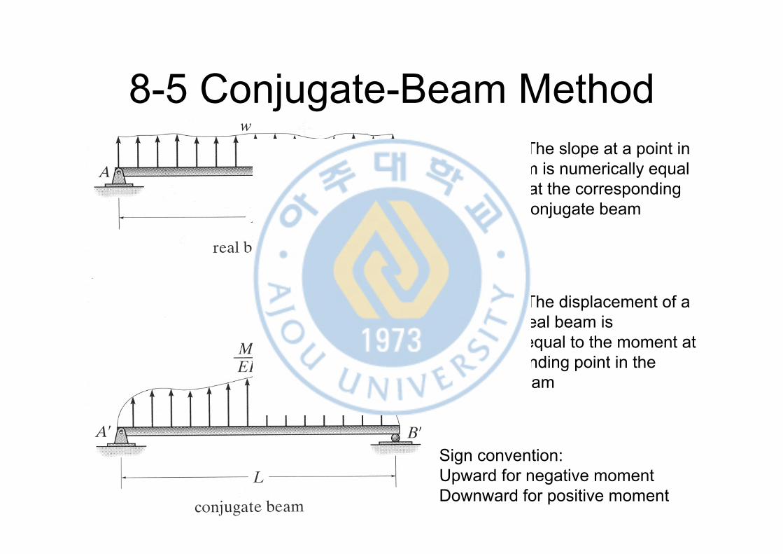
8-5 Conjugate-Beam MethodTheorem 1: The slope at a point in the real beam is numerically equal to the shear at the corresponding point in the conjugate beam
Theorem 2: The displacement of a point in the real beam is numerically equal to the moment at the corresponding point in the conjugate beam
Sign convention:Upward for negative momentDownward for positive moment
8-5 Conjugate-Beam Method
• A pin or roller support at the end of the real beam provides zero displacement but the beam has a non-zero slope
• Consequently from Theorem 1 and 2, the conjugate beam must be supported by a pin or roller since this support has zero moment but has a shear or end reaction
• When the real beam is fixed supported, the conjugate beam has a free end since at this end there is zero shear and moment

8-5 Conjugate-Beam Method

Example 8-12 Determine the slope & deflection at point B of the steel beam where E = 200 GPa and I = 475106 mm4

rad00263.010475200000
105.2
50001010021
6
11
6
'
EI
VBB
mmM BB
9.21325000500000263.0'
EI100
EI250
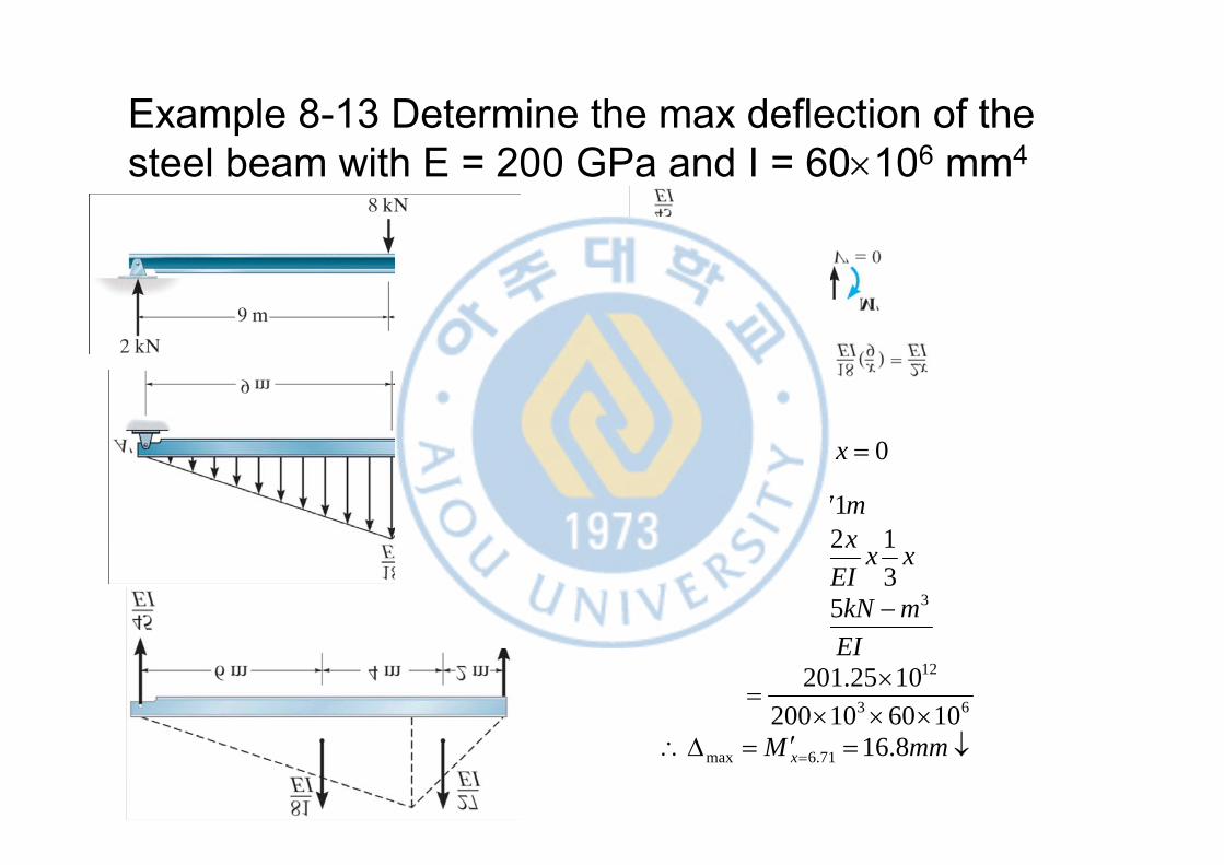
Example 8-13 Determine the max deflection of the steel beam with E = 200 GPa and I = 60106 mm4
mmM
EImkNM
xxEI
xxEI
M
mx
xEI
xEI
V
x
x
x
x
8.16106010200
1025.201
25.201312
214571.653
022145
71.6max
63
12
3
71.6

Example 8-14 Deflection at center C

Example 8-15 Displacement at pin B and slope of each beam segment about the pin