Chapter 4site.iugaza.edu.ps/mhaiba/files/2012/01/Ch-4-Deflection-and... · Chapter Outline Dr....
82
Chapter 4 Deflection and Stiffness March 24, 2014 Dr. Mohammad Suliman Abuhaiba, PE 1
Transcript of Chapter 4site.iugaza.edu.ps/mhaiba/files/2012/01/Ch-4-Deflection-and... · Chapter Outline Dr....

Chapter 4 Deflection and Stiffness
March 24, 2014
Dr. Mohammad Suliman Abuhaiba, PE 1
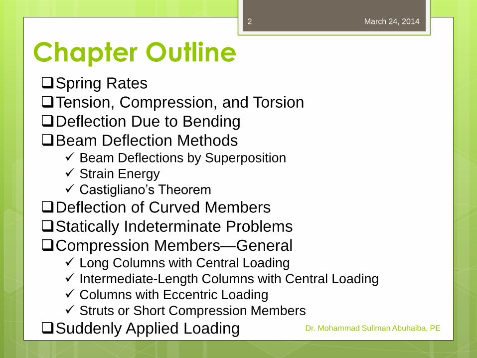
Chapter Outline
Dr. Mohammad Suliman Abuhaiba, PE
Spring Rates
Tension, Compression, and Torsion
Deflection Due to Bending
Beam Deflection Methods Beam Deflections by Superposition
Strain Energy
Castigliano’s Theorem
Deflection of Curved Members
Statically Indeterminate Problems
Compression Members—General Long Columns with Central Loading
Intermediate-Length Columns with Central Loading
Columns with Eccentric Loading
Struts or Short Compression Members
Suddenly Applied Loading
March 24, 2014 2

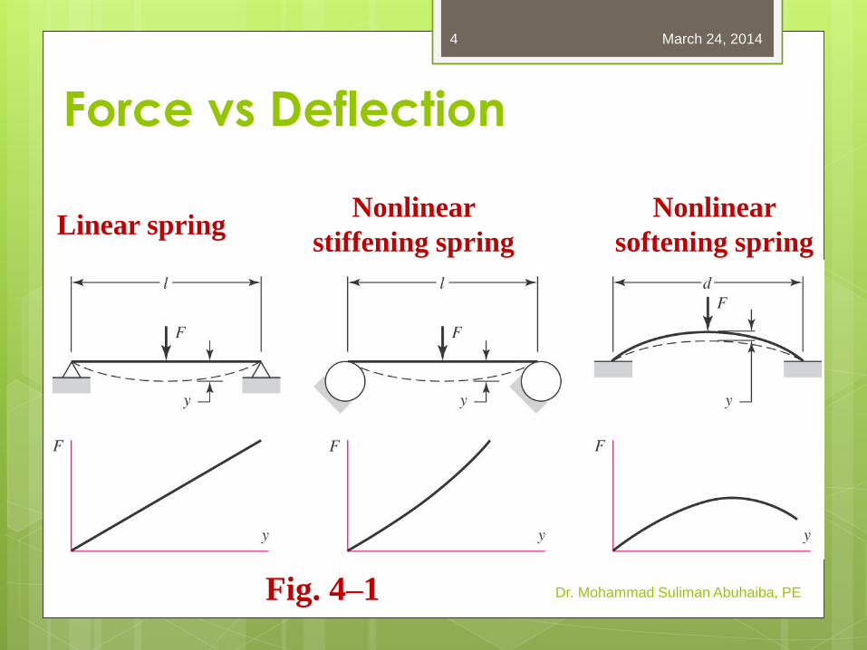
Force vs Deflection
Elasticity:property of a material that
enables it to regain its original configuration
after deformation
Spring: a mechanical element that exerts a force when deformed
Dr. Mohammad Suliman Abuhaiba, PE
March 24, 2014 3
Force vs Deflection
Dr. Mohammad Suliman Abuhaiba, PE
Linear spring Nonlinear
stiffening spring
Nonlinear
softening spring
Fig. 4–1
March 24, 2014 4
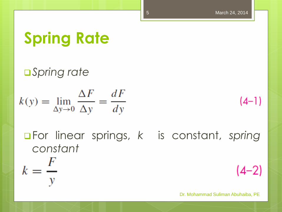
Spring Rate
Spring rate
For linear springs, k is constant, spring
constant
Dr. Mohammad Suliman Abuhaiba, PE
March 24, 2014 5
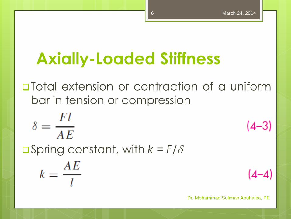
Axially-Loaded Stiffness
Total extension or contraction of a uniform
bar in tension or compression
Spring constant, with k = F/d
Dr. Mohammad Suliman Abuhaiba, PE
March 24, 2014 6
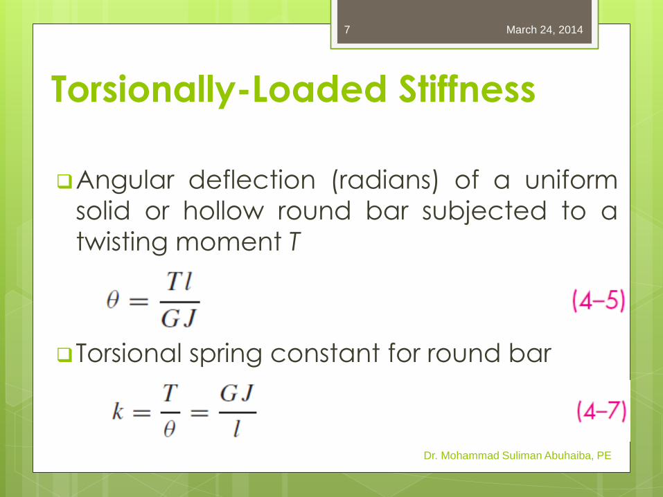
Torsionally-Loaded Stiffness
Angular deflection (radians) of a uniform
solid or hollow round bar subjected to a
twisting moment T
Torsional spring constant for round bar
Dr. Mohammad Suliman Abuhaiba, PE
March 24, 2014 7
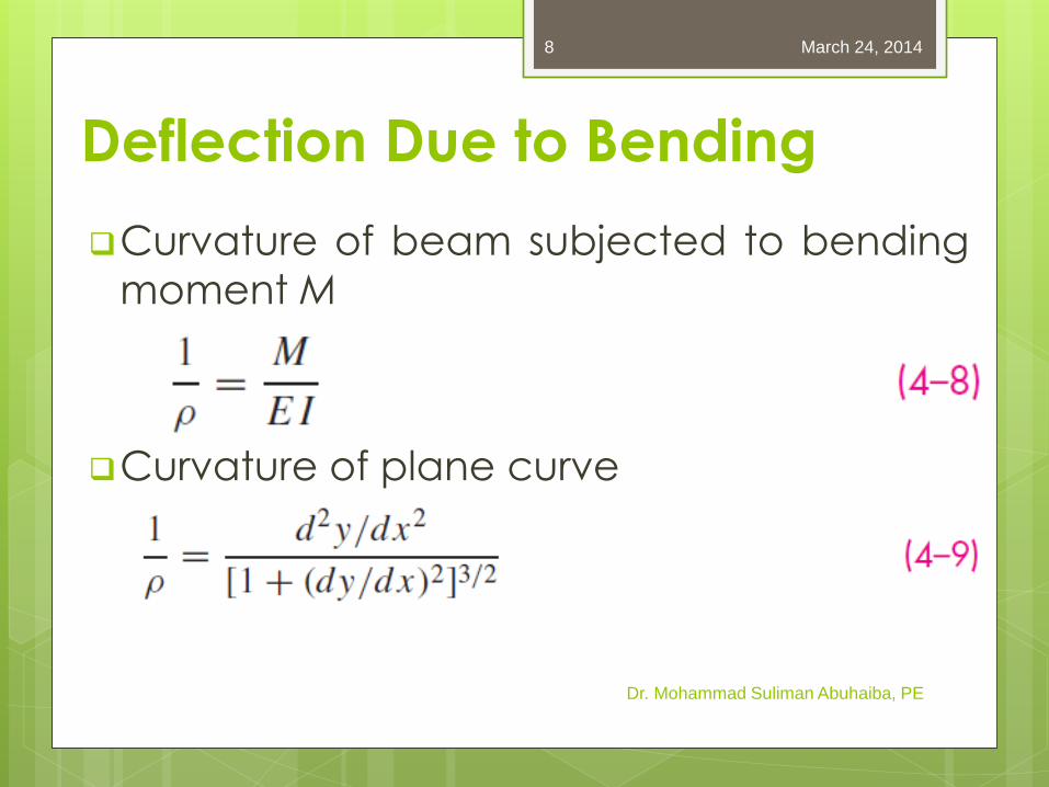
Deflection Due to Bending
Curvature of beam subjected to bending
moment M
Curvature of plane curve
Dr. Mohammad Suliman Abuhaiba, PE
March 24, 2014 8
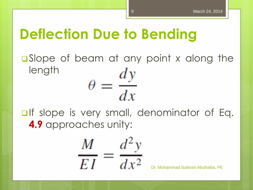
Deflection Due to Bending
Slope of beam at any point x along the
length
If slope is very small, denominator of Eq.
4.9 approaches unity:
Dr. Mohammad Suliman Abuhaiba, PE
March 24, 2014 9
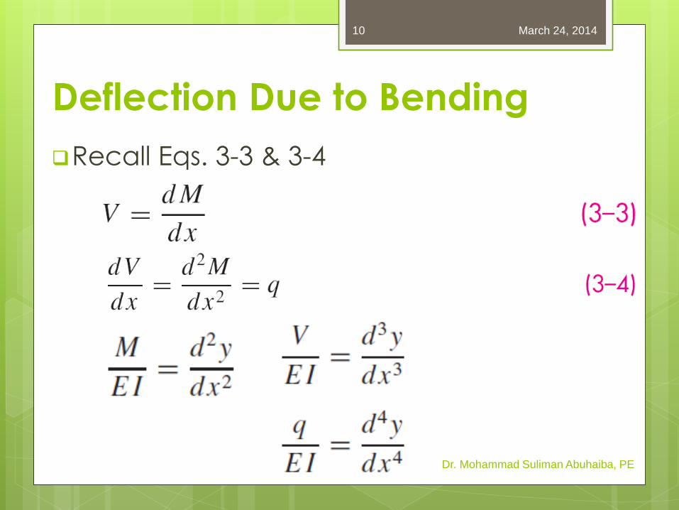
Deflection Due to Bending
Recall Eqs. 3-3 & 3-4
Dr. Mohammad Suliman Abuhaiba, PE
March 24, 2014 10
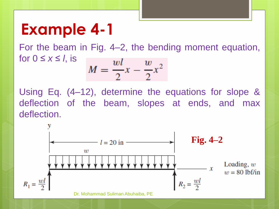
Example 4-1
Dr. Mohammad Suliman Abuhaiba, PE
Fig. 4–2
For the beam in Fig. 4–2, the bending moment equation,
for 0 ≤ x ≤ l, is
Using Eq. (4–12), determine the equations for slope &
deflection of the beam, slopes at ends, and max
deflection.

HW Assignment #4-1
Problem 4-1
Due Monday 17/3/2014
March 24, 2014
Dr. Mohammad Suliman Abuhaiba, PE
12
Beam Deflection Methods
1. Superposition
2. Moment-area method
3. Numerical integration
4. Castigliano energy method
5. Finite element software
Dr. Mohammad Suliman Abuhaiba, PE
March 24, 2014 13
Beam Deflection by Superposition
Table A-9
Roark’s Formulas for Stress & Strain
Dr. Mohammad Suliman Abuhaiba, PE
March 24, 2014 14
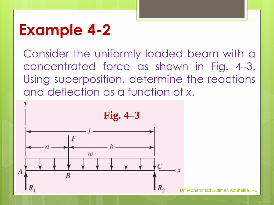
Example 4-2
Consider the uniformly loaded beam with a
concentrated force as shown in Fig. 4–3.
Using superposition, determine the reactions
and deflection as a function of x.
Dr. Mohammad Suliman Abuhaiba, PE
Fig. 4–3
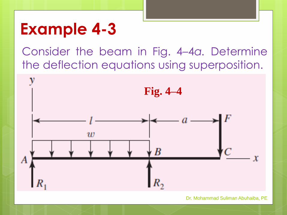
Example 4-3
Consider the beam in Fig. 4–4a. Determine
the deflection equations using superposition.
Dr. Mohammad Suliman Abuhaiba, PE
Fig. 4–4
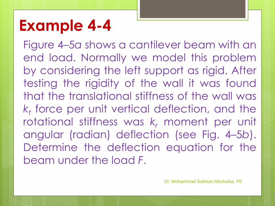
Example 4-4 Figure 4–5a shows a cantilever beam with an
end load. Normally we model this problem
by considering the left support as rigid. After
testing the rigidity of the wall it was found
that the translational stiffness of the wall was
kt force per unit vertical deflection, and the
rotational stiffness was kr moment per unit
angular (radian) deflection (see Fig. 4–5b).
Determine the deflection equation for the
beam under the load F.
Dr. Mohammad Suliman Abuhaiba, PE
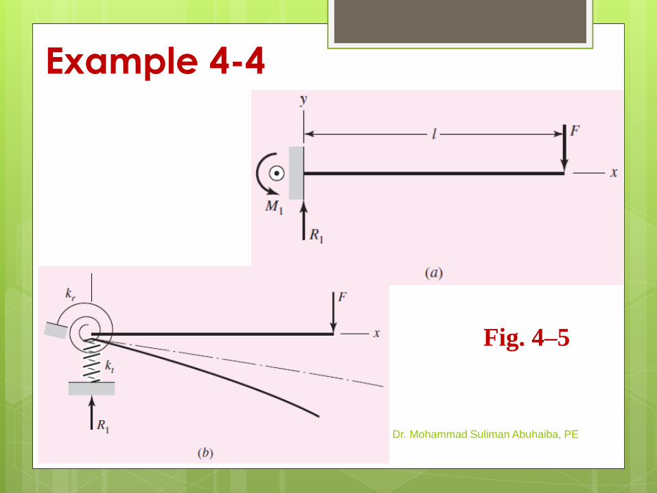
Example 4-4
Dr. Mohammad Suliman Abuhaiba, PE
Fig. 4–5

HW Assignment #4-2
Problems: 4.10, 4.14, 4.41
Due Wednesday
19/3/2014
March 24, 2014
Dr. Mohammad Suliman Abuhaiba, PE
19
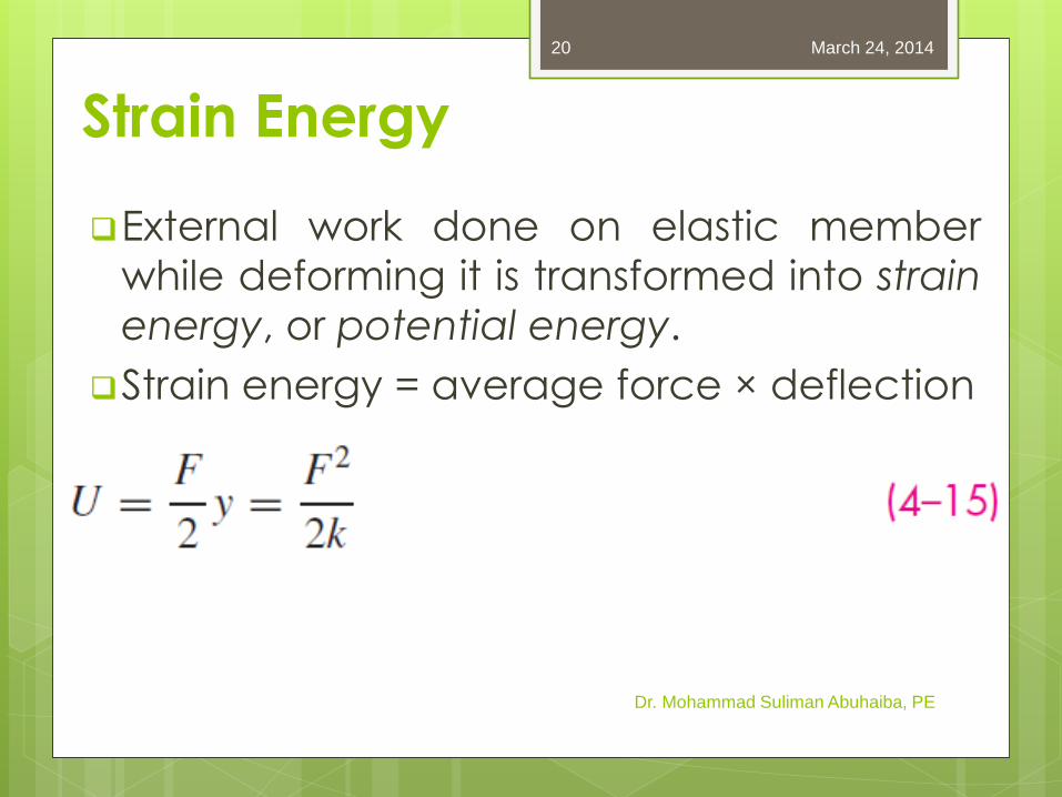
Strain Energy
External work done on elastic member
while deforming it is transformed into strain
energy, or potential energy.
Strain energy = average force × deflection
Dr. Mohammad Suliman Abuhaiba, PE
March 24, 2014 20
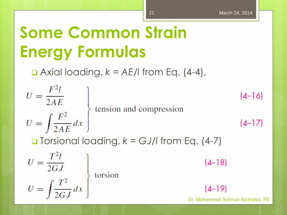
Axial loading, k = AE/l from Eq. (4-4),
Torsional loading, k = GJ/l from Eq. (4-7)
Some Common Strain
Energy Formulas
Dr. Mohammad Suliman Abuhaiba, PE
March 24, 2014 21
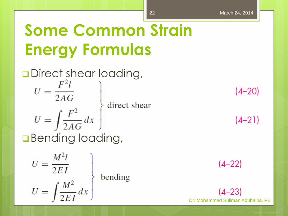
Some Common Strain
Energy Formulas
Direct shear loading,
Bending loading,
Dr. Mohammad Suliman Abuhaiba, PE
March 24, 2014 22
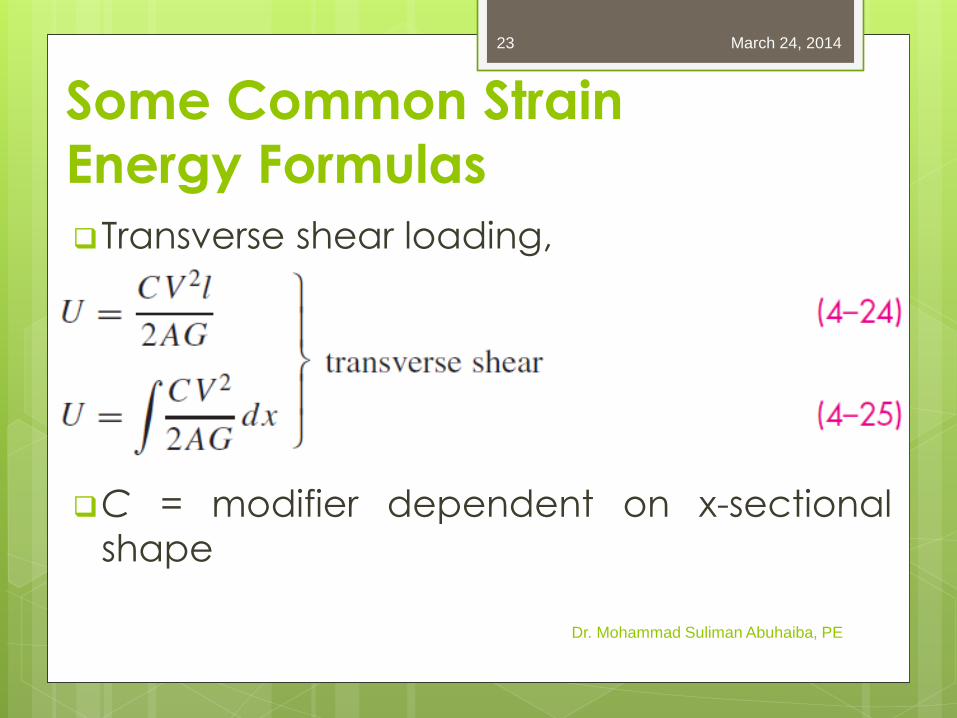
Some Common Strain
Energy Formulas
Transverse shear loading,
C = modifier dependent on x-sectional
shape
Dr. Mohammad Suliman Abuhaiba, PE
March 24, 2014 23
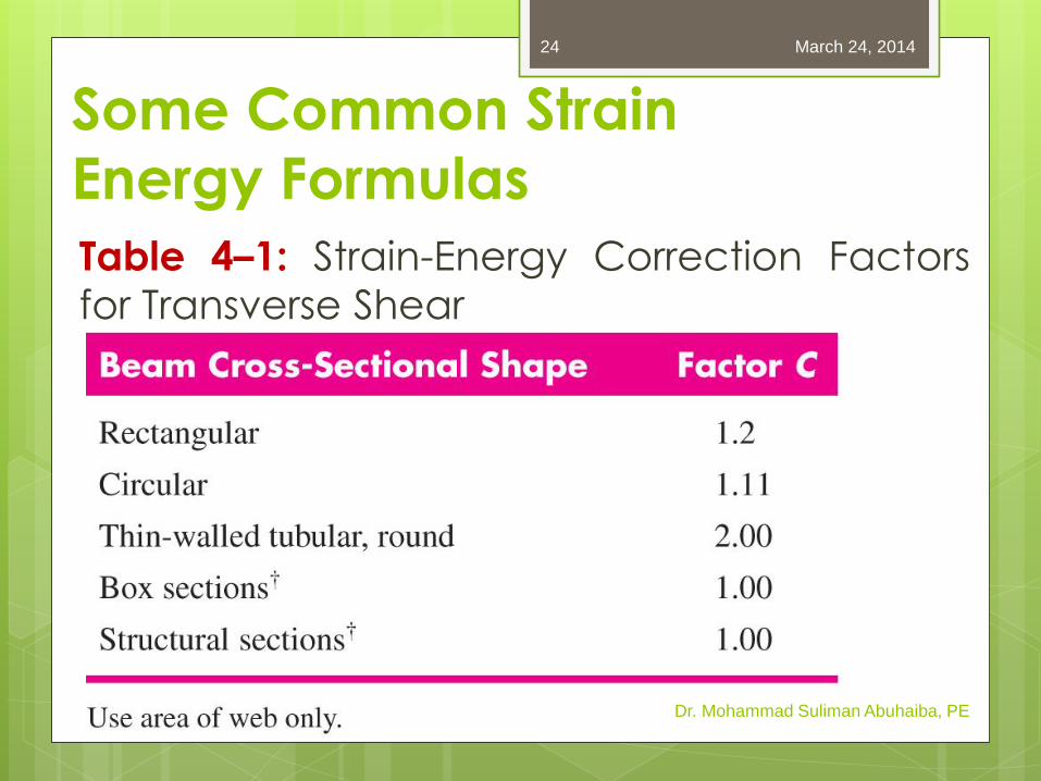
Some Common Strain
Energy Formulas
Table 4–1: Strain-Energy Correction Factors
for Transverse Shear
Dr. Mohammad Suliman Abuhaiba, PE
March 24, 2014 24
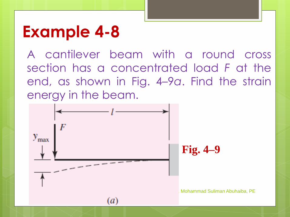
Example 4-8
A cantilever beam with a round cross
section has a concentrated load F at the
end, as shown in Fig. 4–9a. Find the strain
energy in the beam.
Dr. Mohammad Suliman Abuhaiba, PE
Fig. 4–9
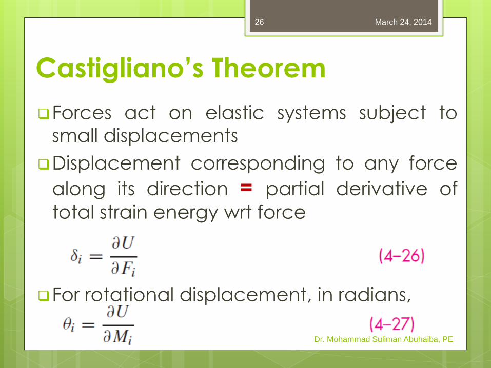
Forces act on elastic systems subject to
small displacements
Displacement corresponding to any force
along its direction = partial derivative of
total strain energy wrt force
For rotational displacement, in radians,
Castigliano’s Theorem
Dr. Mohammad Suliman Abuhaiba, PE
March 24, 2014 26

Example 4-9 The cantilever of Ex. 4–8 is a carbon steel bar 10 in
long with a 1-in diameter and is loaded by a force F
= 100 lbf.
a. Find max deflection using Castigliano’s theorem,
including that due to shear.
b. What error is introduced if shear is neglected?
Dr. Mohammad Suliman Abuhaiba, PE
Fig. 4–9
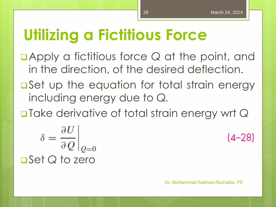
Utilizing a Fictitious Force
Apply a fictitious force Q at the point, and
in the direction, of the desired deflection.
Set up the equation for total strain energy
including energy due to Q.
Take derivative of total strain energy wrt Q
Set Q to zero
Dr. Mohammad Suliman Abuhaiba, PE
March 24, 2014 28
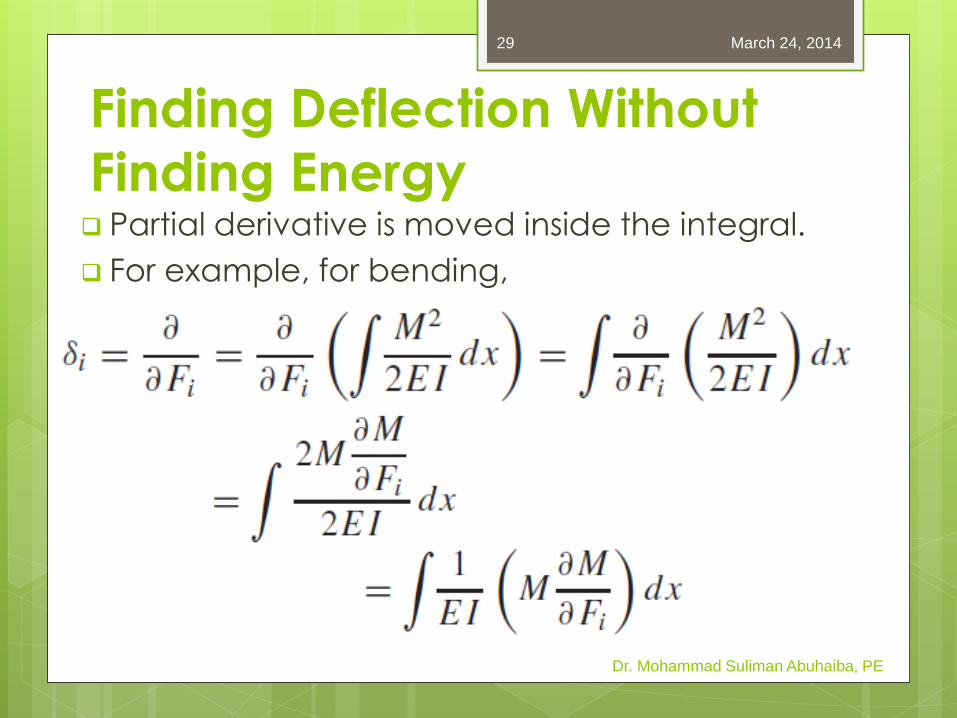
Finding Deflection Without
Finding Energy Partial derivative is moved inside the integral.
For example, for bending,
Dr. Mohammad Suliman Abuhaiba, PE
March 24, 2014 29
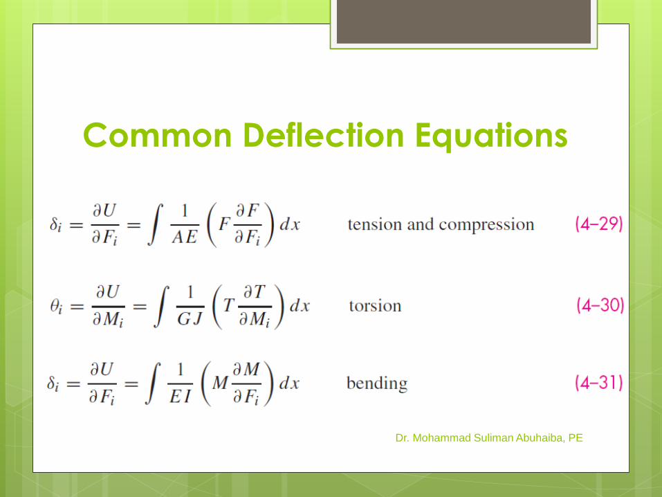
Common Deflection Equations
Dr. Mohammad Suliman Abuhaiba, PE
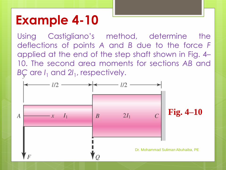
Example 4-10 Using Castigliano’s method, determine the
deflections of points A and B due to the force F
applied at the end of the step shaft shown in Fig. 4–
10. The second area moments for sections AB and
BC are I1 and 2I1, respectively.
Dr. Mohammad Suliman Abuhaiba, PE
Fig. 4–10
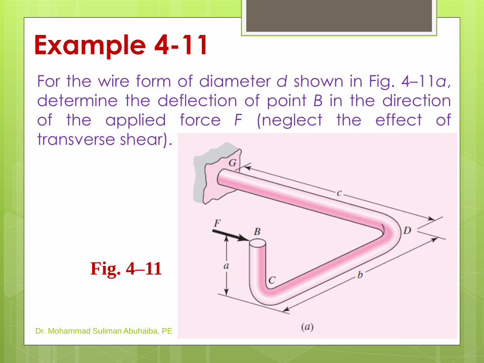
Example 4-11
For the wire form of diameter d shown in Fig. 4–11a,
determine the deflection of point B in the direction
of the applied force F (neglect the effect of
transverse shear).
Dr. Mohammad Suliman Abuhaiba, PE
Fig. 4–11
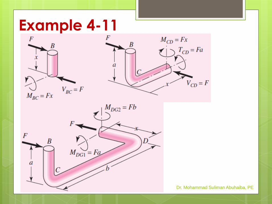
Example 4-11
Dr. Mohammad Suliman Abuhaiba, PE

HW Assignment #4-3
Problems: 4.67, 4.70
Due Saturday 22/3/2014
March 24, 2014
Dr. Mohammad Suliman Abuhaiba, PE
34
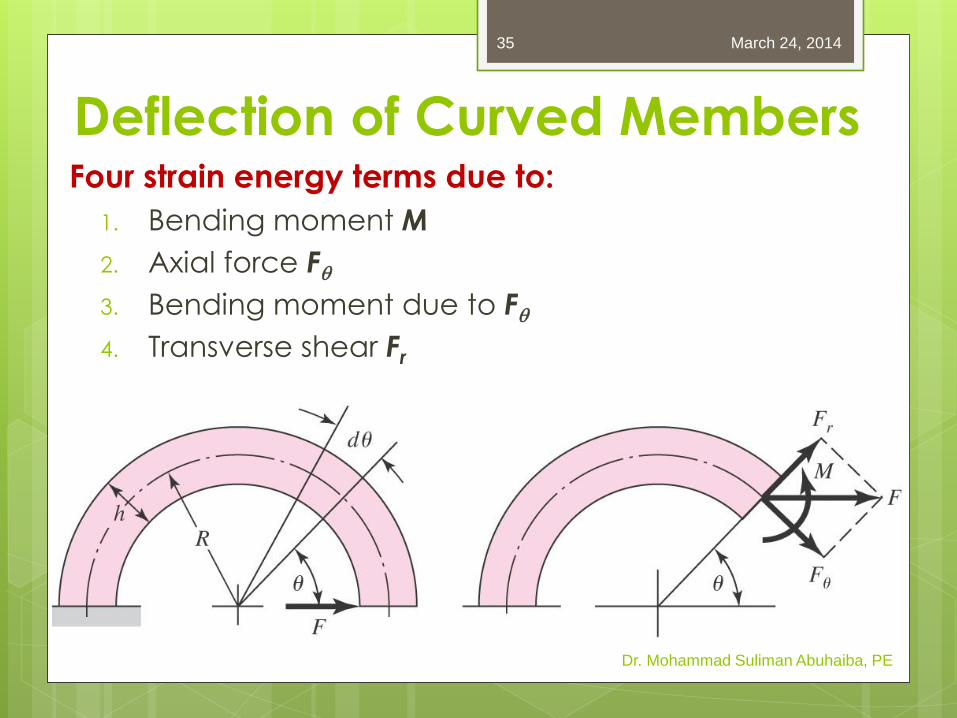
Deflection of Curved Members Four strain energy terms due to:
1. Bending moment M
2. Axial force Fq
3. Bending moment due to Fq
4. Transverse shear Fr
Dr. Mohammad Suliman Abuhaiba, PE
March 24, 2014 35
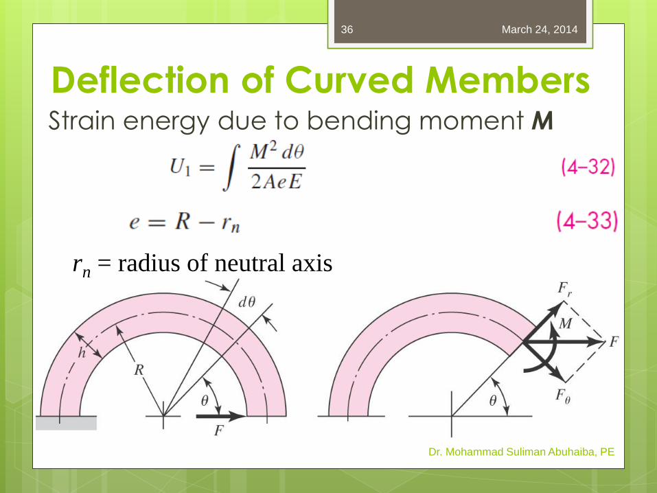
Strain energy due to bending moment M
Dr. Mohammad Suliman Abuhaiba, PE
rn = radius of neutral axis
March 24, 2014 36
Deflection of Curved Members
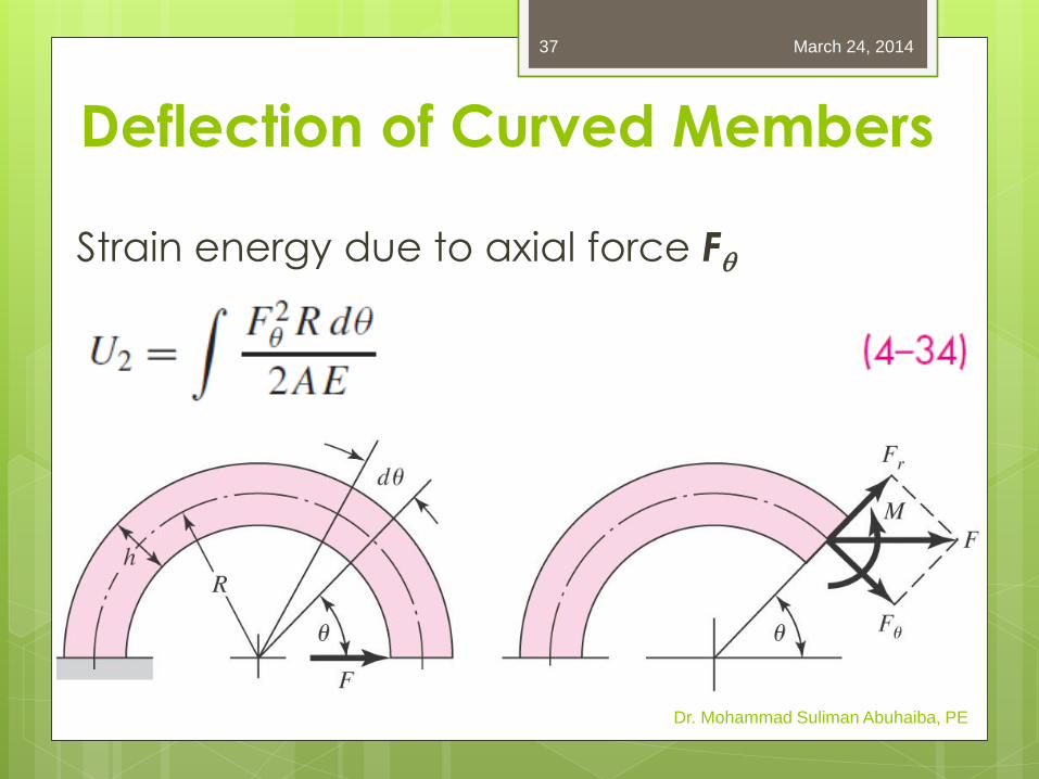
Strain energy due to axial force Fq
Dr. Mohammad Suliman Abuhaiba, PE
March 24, 2014 37
Deflection of Curved Members
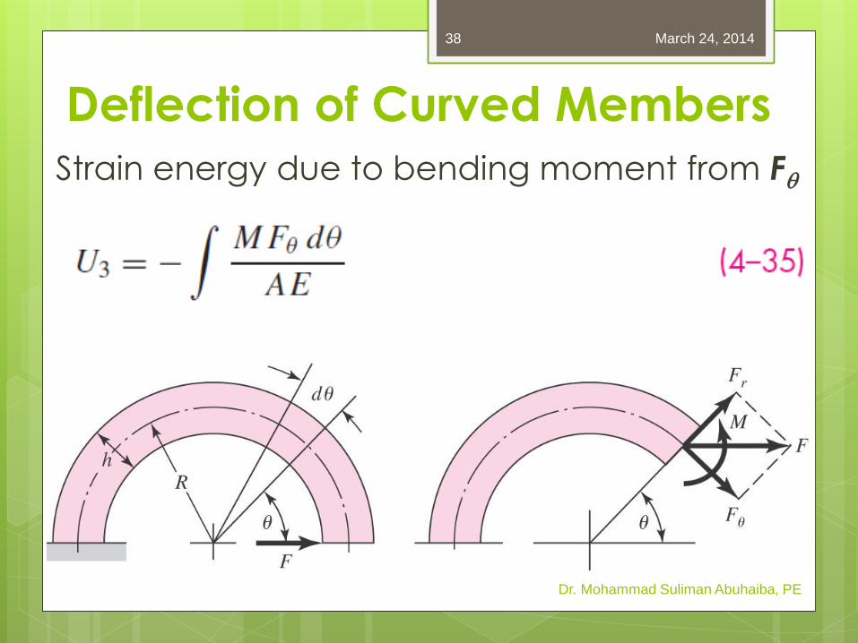
Strain energy due to bending moment from Fq
Dr. Mohammad Suliman Abuhaiba, PE
March 24, 2014 38
Deflection of Curved Members
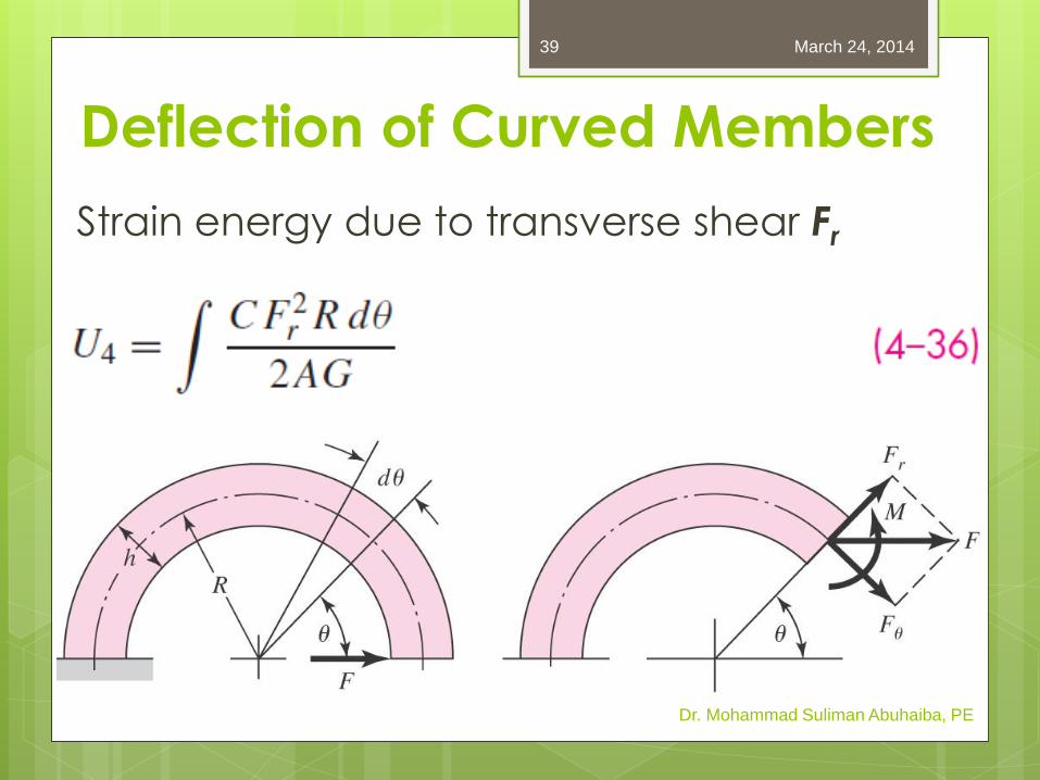
Strain energy due to transverse shear Fr
Dr. Mohammad Suliman Abuhaiba, PE
March 24, 2014 39
Deflection of Curved Members
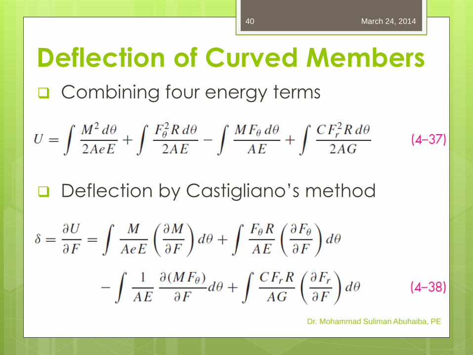
Combining four energy terms
Deflection by Castigliano’s method
Dr. Mohammad Suliman Abuhaiba, PE
March 24, 2014 40
Deflection of Curved Members
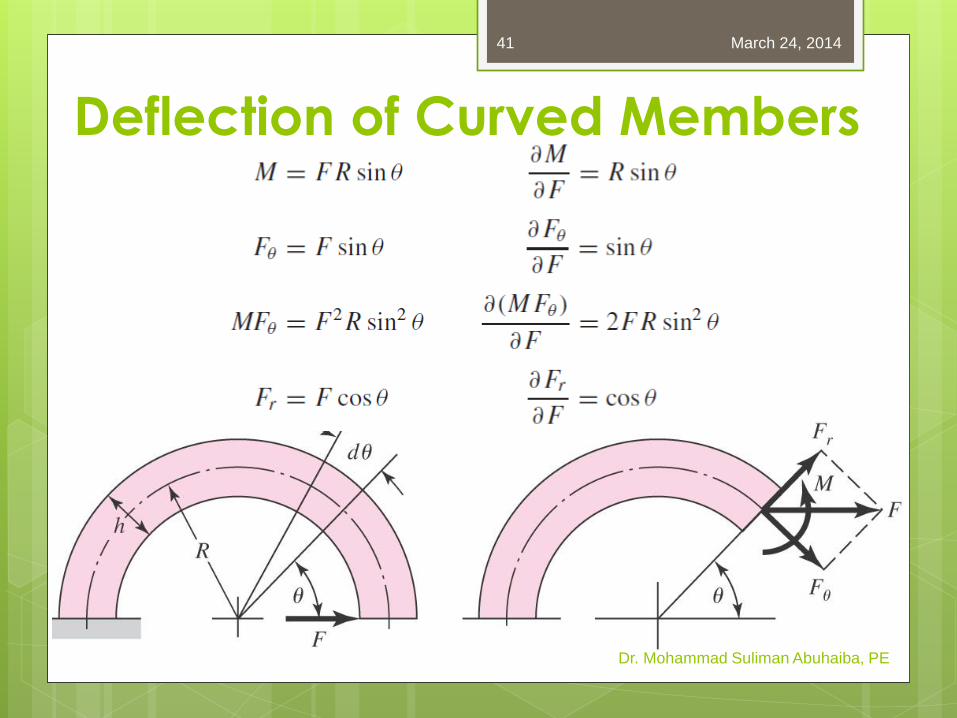
Dr. Mohammad Suliman Abuhaiba, PE
March 24, 2014 41
Deflection of Curved Members
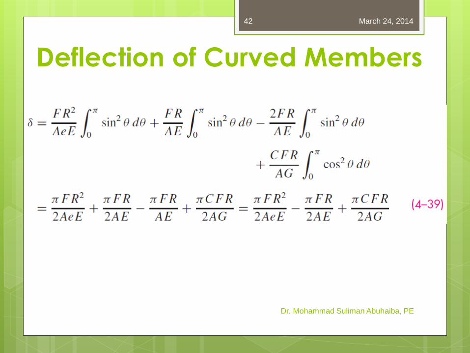
Dr. Mohammad Suliman Abuhaiba, PE
March 24, 2014 42
Deflection of Curved Members
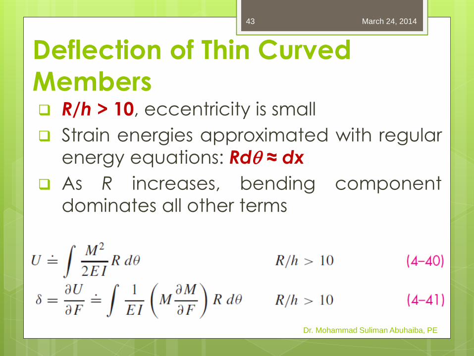
Deflection of Thin Curved
Members R/h > 10, eccentricity is small
Strain energies approximated with regular
energy equations: Rdq ≈ dx
As R increases, bending component
dominates all other terms
Dr. Mohammad Suliman Abuhaiba, PE
March 24, 2014 43
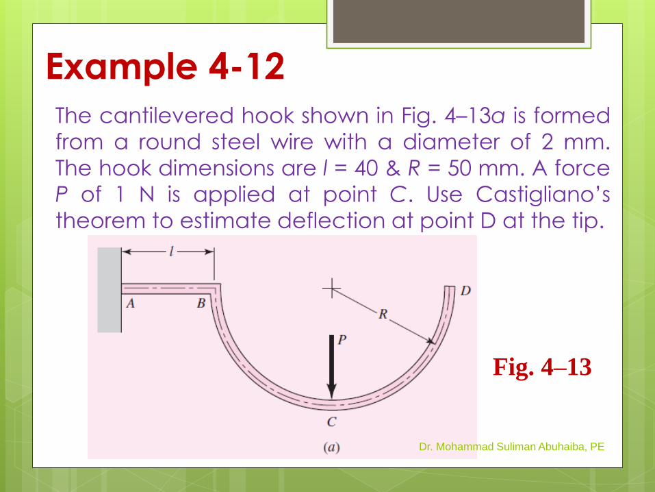
Example 4-12
The cantilevered hook shown in Fig. 4–13a is formed
from a round steel wire with a diameter of 2 mm.
The hook dimensions are l = 40 & R = 50 mm. A force
P of 1 N is applied at point C. Use Castigliano’s
theorem to estimate deflection at point D at the tip.
Dr. Mohammad Suliman Abuhaiba, PE
Fig. 4–13

HW Assignment #4-4
Problems: 4.78
Due Monday 24/3/2014
March 24, 2014
Dr. Mohammad Suliman Abuhaiba, PE
45
Statically Indeterminate
Problems
Redundant supports: extra constraint
supports
A deflection equation is required for each
redundant support.
Dr. Mohammad Suliman Abuhaiba, PE
March 24, 2014 46
Procedure 1 for Statically
Indeterminate Problems 1. Choose redundant reactions
2. Write equations of static equilibrium for
remaining reactions in terms of applied
loads & redundant reactions.
3. Write deflection equations for points at
locations of redundant reactions in terms
of applied loads and redundant
reactions.
4. Solve equilibrium & deflection equations Dr. Mohammad Suliman Abuhaiba, PE
March 24, 2014 47
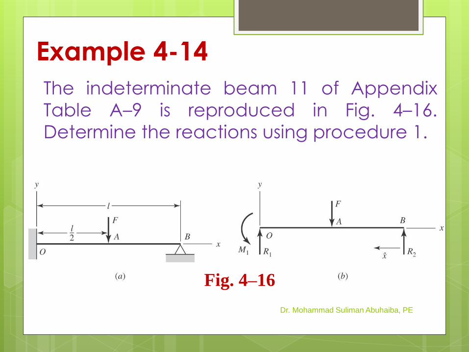
Example 4-14
The indeterminate beam 11 of Appendix
Table A–9 is reproduced in Fig. 4–16.
Determine the reactions using procedure 1.
Dr. Mohammad Suliman Abuhaiba, PE
Fig. 4–16
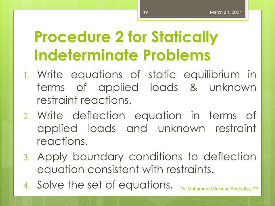
Procedure 2 for Statically
Indeterminate Problems 1. Write equations of static equilibrium in
terms of applied loads & unknown
restraint reactions.
2. Write deflection equation in terms of
applied loads and unknown restraint
reactions.
3. Apply boundary conditions to deflection
equation consistent with restraints.
4. Solve the set of equations. Dr. Mohammad Suliman Abuhaiba, PE
March 24, 2014 49
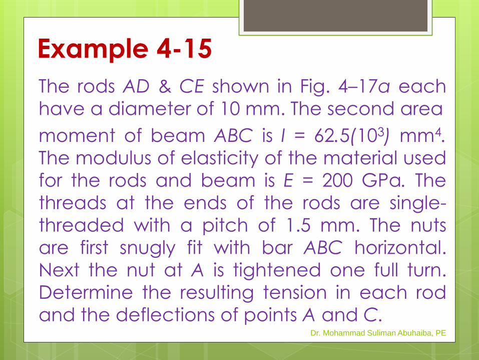
Example 4-15
The rods AD & CE shown in Fig. 4–17a each
have a diameter of 10 mm. The second area
moment of beam ABC is I = 62.5(103) mm4.
The modulus of elasticity of the material used
for the rods and beam is E = 200 GPa. The
threads at the ends of the rods are single-
threaded with a pitch of 1.5 mm. The nuts
are first snugly fit with bar ABC horizontal.
Next the nut at A is tightened one full turn.
Determine the resulting tension in each rod
and the deflections of points A and C. Dr. Mohammad Suliman Abuhaiba, PE
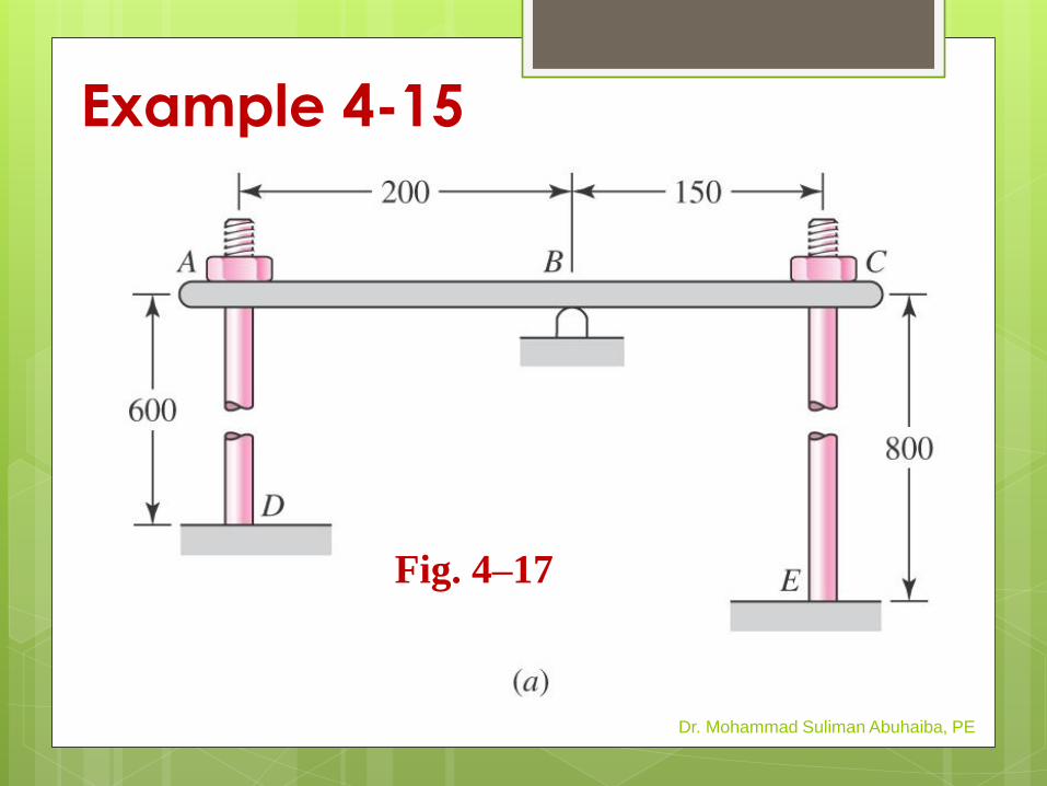
Example 4-15
Dr. Mohammad Suliman Abuhaiba, PE
Fig. 4–17

HW Assignment #4-5
Problems: 4.95, 4.97
Due Wednesday
26/3/2014
March 24, 2014
Dr. Mohammad Suliman Abuhaiba, PE
52
Compression Members
Column:
A member loaded in compression
either its length or eccentric loading
causes it to experience more than
pure compression
Dr. Mohammad Suliman Abuhaiba, PE
March 24, 2014 53
Compression Members
Four categories of columns
1. Long columns with central loading
2. Intermediate-length columns with
central loading
3. Columns with eccentric loading
4. Struts or short columns with eccentric
loading
Dr. Mohammad Suliman Abuhaiba, PE
March 24, 2014 54
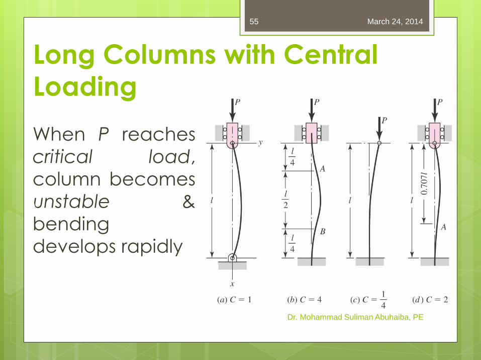
Long Columns with Central
Loading
When P reaches
critical load,
column becomes
unstable &
bending
develops rapidly
Dr. Mohammad Suliman Abuhaiba, PE
March 24, 2014 55

Euler Column Formula Pin-ended
column,
Other end conditions: apply
a constant C for each end
condition
Dr. Mohammad Suliman Abuhaiba, PE
March 24, 2014 56
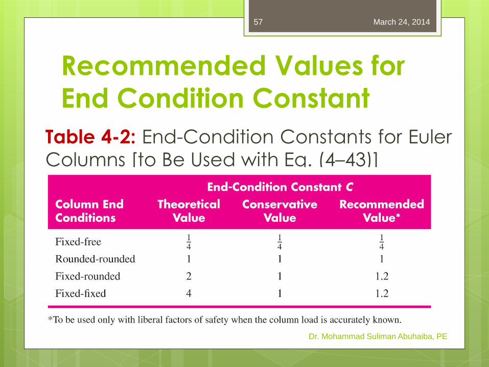
Recommended Values for
End Condition Constant
Table 4-2: End-Condition Constants for Euler
Columns [to Be Used with Eq. (4–43)]
Dr. Mohammad Suliman Abuhaiba, PE
March 24, 2014 57
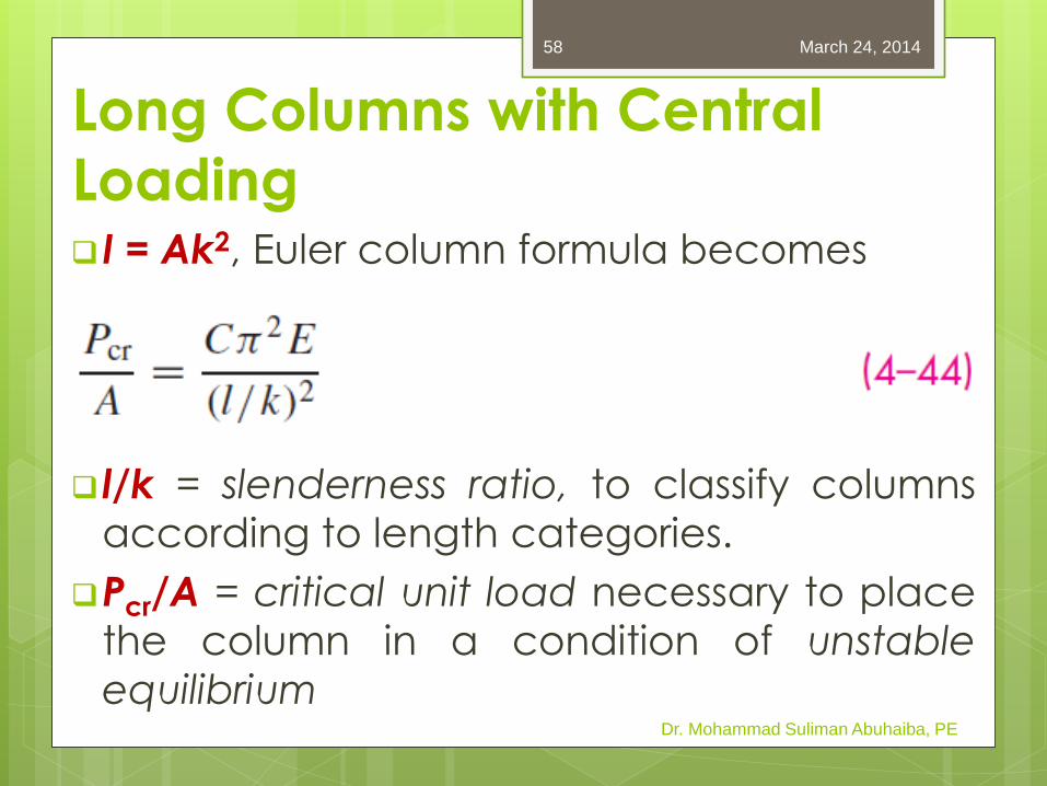
Long Columns with Central
Loading I = Ak2, Euler column formula becomes
l/k = slenderness ratio, to classify columns according to length categories.
Pcr/A = critical unit load necessary to place
the column in a condition of unstable
equilibrium Dr. Mohammad Suliman Abuhaiba, PE
March 24, 2014 58
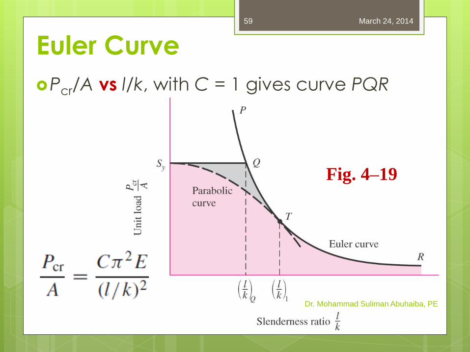
Euler Curve
Pcr/A vs l/k, with C = 1 gives curve PQR
Dr. Mohammad Suliman Abuhaiba, PE
Fig. 4–19
March 24, 2014 59
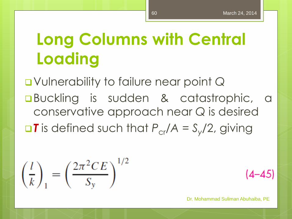
Long Columns with Central
Loading
Vulnerability to failure near point Q
Buckling is sudden & catastrophic, a
conservative approach near Q is desired
T is defined such that Pcr/A = Sy/2, giving
Dr. Mohammad Suliman Abuhaiba, PE
March 24, 2014 60
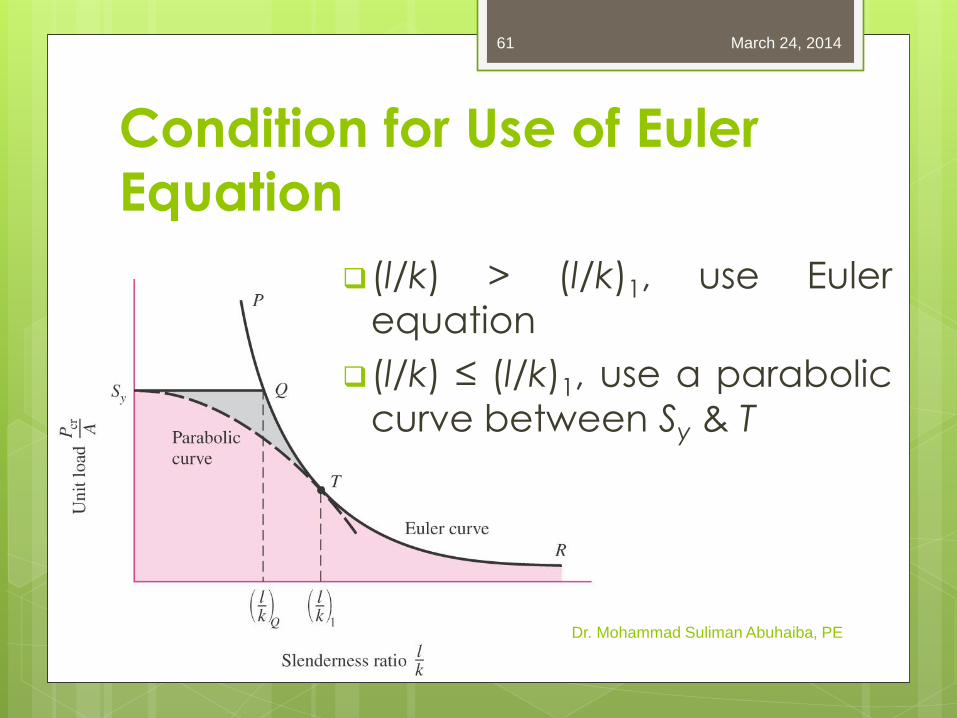
Condition for Use of Euler
Equation
(l/k) > (l/k)1, use Euler
equation
(l/k) ≤ (l/k)1, use a parabolic
curve between Sy & T
Dr. Mohammad Suliman Abuhaiba, PE
March 24, 2014 61
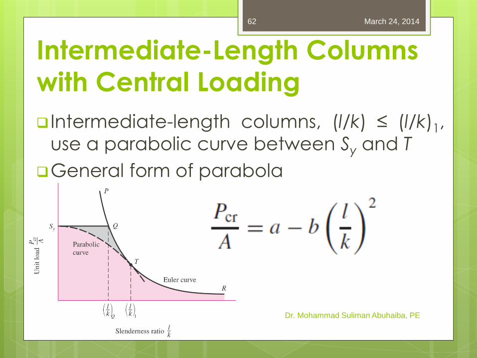
Intermediate-Length Columns
with Central Loading
Intermediate-length columns, (l/k) ≤ (l/k)1,
use a parabolic curve between Sy and T
General form of parabola
Dr. Mohammad Suliman Abuhaiba, PE
March 24, 2014 62

If parabola starts at Sy, then a = Sy
Intermediate-Length Columns
with Central Loading
Dr. Mohammad Suliman Abuhaiba, PE
March 24, 2014 63
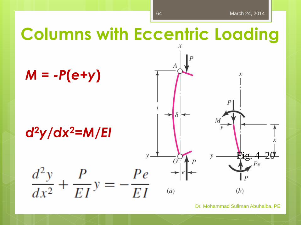
Columns with Eccentric Loading
M = -P(e+y)
d2y/dx2=M/EI
Dr. Mohammad Suliman Abuhaiba, PE
Fig. 4–20
March 24, 2014 64
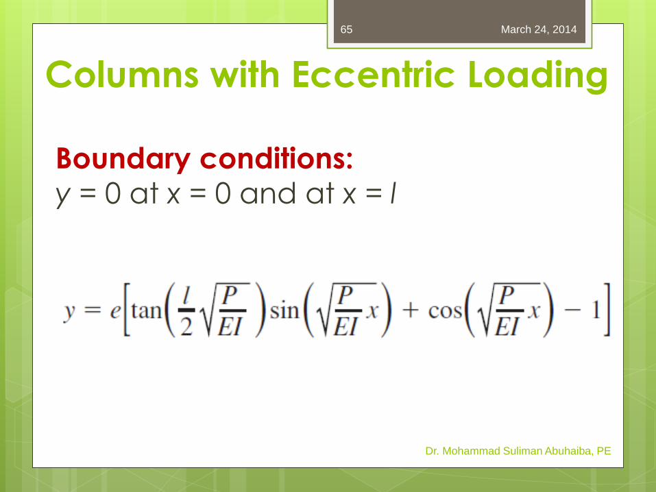
Columns with Eccentric Loading
Boundary conditions:
y = 0 at x = 0 and at x = l
Dr. Mohammad Suliman Abuhaiba, PE
March 24, 2014 65
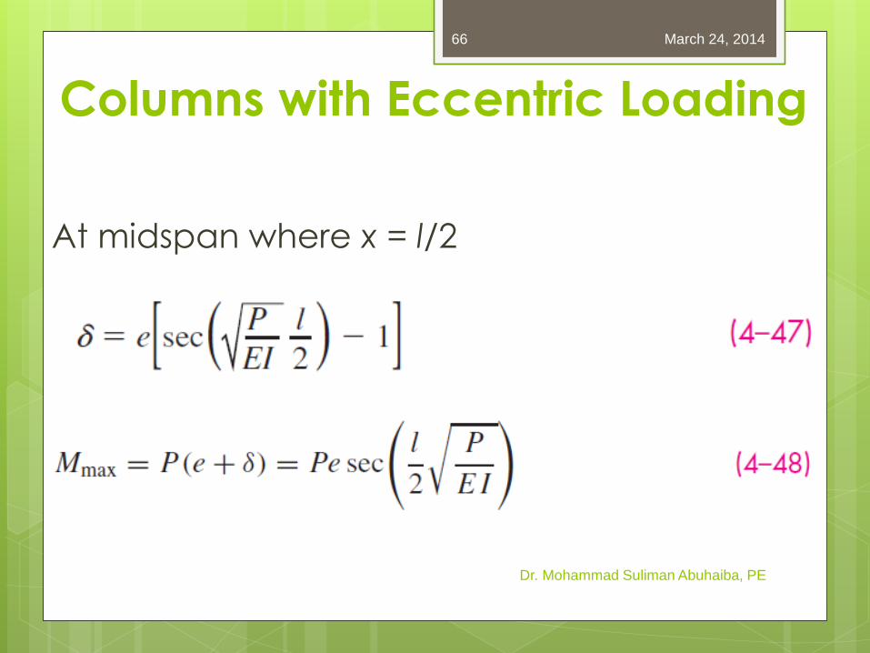
At midspan where x = l/2
Dr. Mohammad Suliman Abuhaiba, PE
March 24, 2014 66
Columns with Eccentric Loading
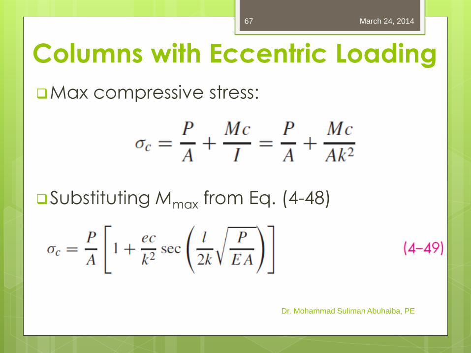
Max compressive stress:
Substituting Mmax from Eq. (4-48)
Dr. Mohammad Suliman Abuhaiba, PE
March 24, 2014 67
Columns with Eccentric Loading
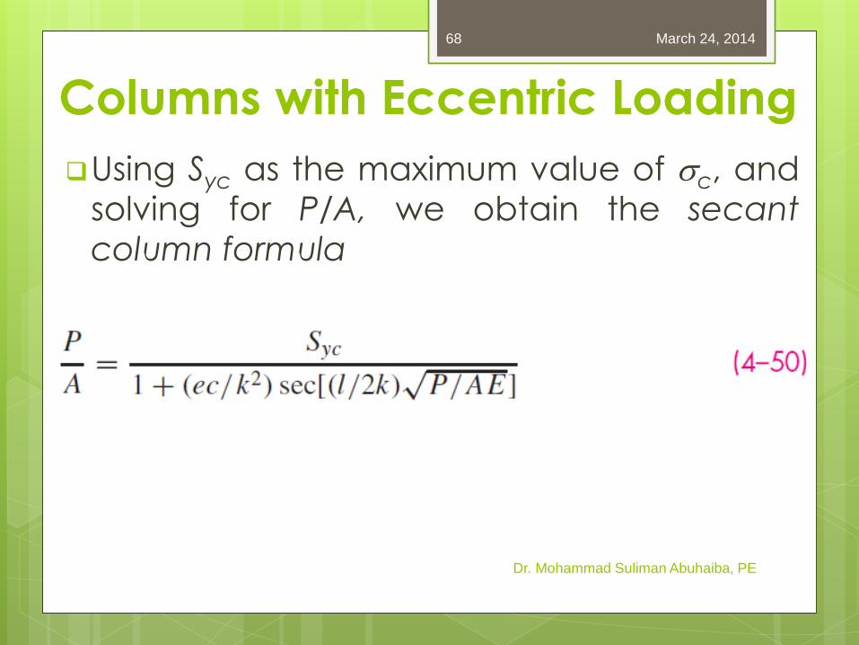
Using Syc as the maximum value of sc, and solving for P/A, we obtain the secant
column formula
Dr. Mohammad Suliman Abuhaiba, PE
March 24, 2014 68
Columns with Eccentric Loading
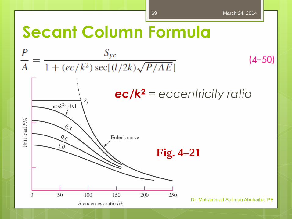
Secant Column Formula
ec/k2 = eccentricity ratio
Dr. Mohammad Suliman Abuhaiba, PE
Fig. 4–21
March 24, 2014 69
Example 4-16
Develop specific Euler equations for the
sizes of columns having
a. Round cross sections
b. Rectangular cross sections
Dr. Mohammad Suliman Abuhaiba, PE
Example 4-17
Specify the diameter of a round column 1.5
m long that is to carry a maximum load
estimated to be 22 kN. Use a design factor
nd = 4 and consider the ends as pinned
(rounded). The column material selected
has a minimum yield strength of 500 MPa
and a modulus of elasticity of 207 GPa.
Dr. Mohammad Suliman Abuhaiba, PE
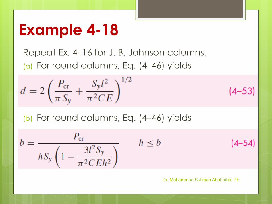
Example 4-18
Repeat Ex. 4–16 for J. B. Johnson columns.
(a) For round columns, Eq. (4–46) yields
(b) For round columns, Eq. (4–46) yields
Dr. Mohammad Suliman Abuhaiba, PE
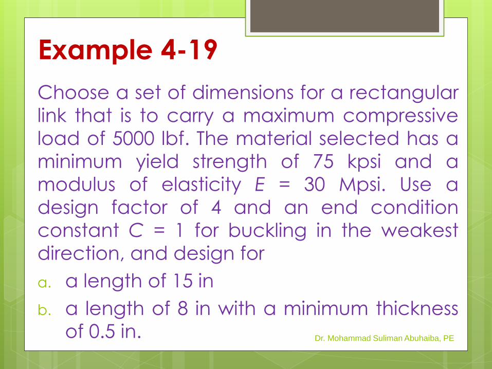
Example 4-19
Choose a set of dimensions for a rectangular
link that is to carry a maximum compressive
load of 5000 lbf. The material selected has a
minimum yield strength of 75 kpsi and a
modulus of elasticity E = 30 Mpsi. Use a
design factor of 4 and an end condition
constant C = 1 for buckling in the weakest
direction, and design for
a. a length of 15 in
b. a length of 8 in with a minimum thickness
of 0.5 in. Dr. Mohammad Suliman Abuhaiba, PE
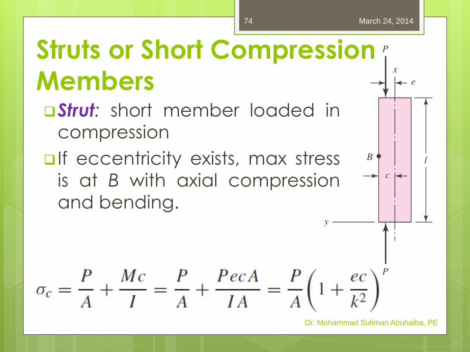
Struts or Short Compression
Members Strut: short member loaded in
compression
If eccentricity exists, max stress
is at B with axial compression
and bending.
Dr. Mohammad Suliman Abuhaiba, PE
March 24, 2014 74
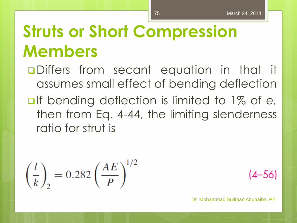
Struts or Short Compression
Members Differs from secant equation in that it
assumes small effect of bending deflection
If bending deflection is limited to 1% of e,
then from Eq. 4-44, the limiting slenderness
ratio for strut is
Dr. Mohammad Suliman Abuhaiba, PE
March 24, 2014 75
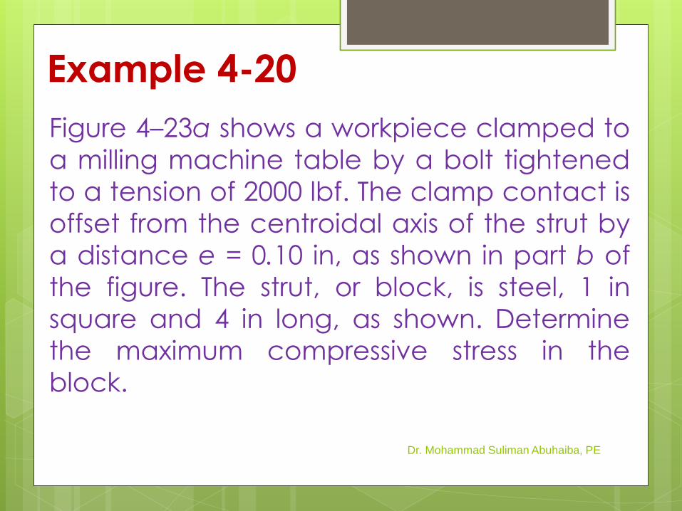
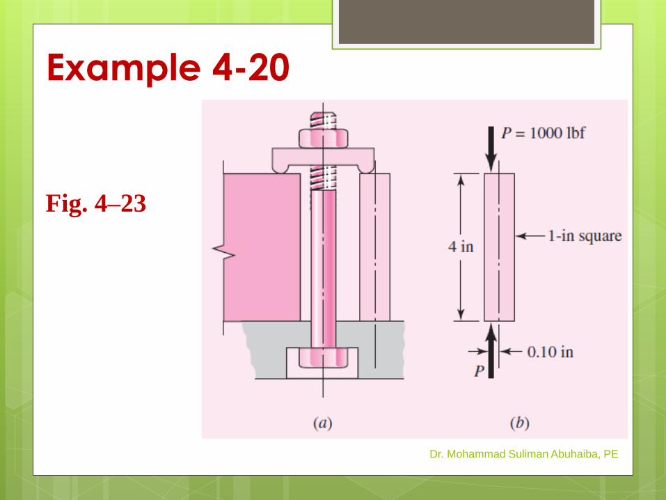
Example 4-20
Figure 4–23a shows a workpiece clamped to
a milling machine table by a bolt tightened
to a tension of 2000 lbf. The clamp contact is
offset from the centroidal axis of the strut by
a distance e = 0.10 in, as shown in part b of
the figure. The strut, or block, is steel, 1 in
square and 4 in long, as shown. Determine
the maximum compressive stress in the
block.
Dr. Mohammad Suliman Abuhaiba, PE
Example 4-20
Dr. Mohammad Suliman Abuhaiba, PE
Fig. 4–23

HW Assignment #4-6
Problems: 4.107, 4.111
Due Saturday 29/3/2014
March 24, 2014
Dr. Mohammad Suliman Abuhaiba, PE
78
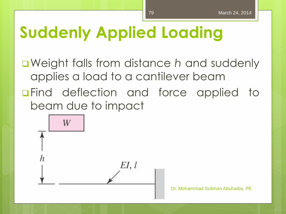
Suddenly Applied Loading
Weight falls from distance h and suddenly
applies a load to a cantilever beam
Find deflection and force applied to
beam due to impact
Dr. Mohammad Suliman Abuhaiba, PE
March 24, 2014 79
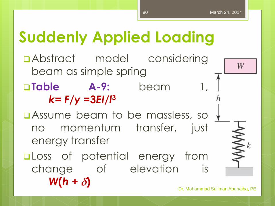
Suddenly Applied Loading
Abstract model considering
beam as simple spring
Table A-9: beam 1,
k= F/y =3EI/l3
Assume beam to be massless, so
no momentum transfer, just
energy transfer
Loss of potential energy from
change of elevation is
W(h + d) Dr. Mohammad Suliman Abuhaiba, PE
March 24, 2014 80
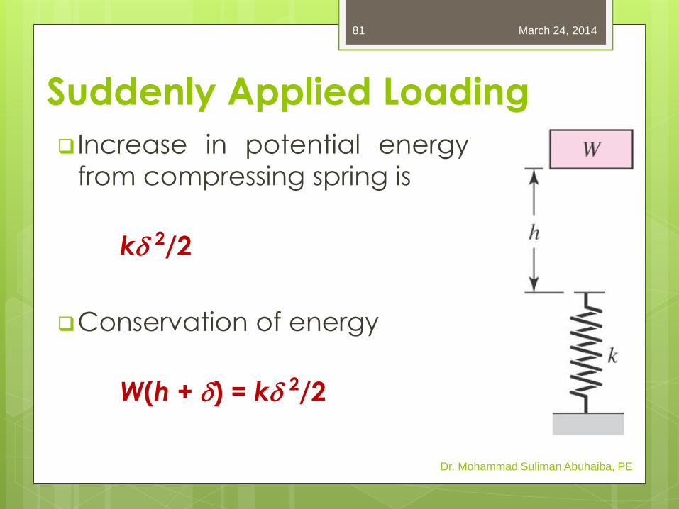
Suddenly Applied Loading
Increase in potential energy
from compressing spring is
kd 2/2
Conservation of energy
W(h + d) = kd 2/2
Dr. Mohammad Suliman Abuhaiba, PE
March 24, 2014 81
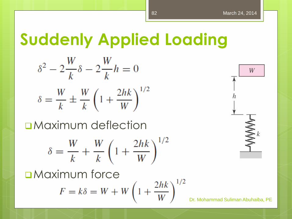
Maximum deflection
Maximum force
Dr. Mohammad Suliman Abuhaiba, PE
March 24, 2014 82
Suddenly Applied Loading