
Chapter 2 Kinematics of particles and rigid bodies (2-1...
53
Chapter 2 Kinematics of particles and rigid bodies (2-1)Basic Concepts Bachelor Program in AUTOMATION ENGINEERING Prof. Rong-yong Zhao ([email protected]) first semester,2013-2014
-
Upload
duongkhanh -
Category
Documents
-
view
236 -
download
2
Transcript of Chapter 2 Kinematics of particles and rigid bodies (2-1...

Chapter 2 Kinematics of particles and rigid bodies
(2-1)Basic Concepts Bachelor Program in AUTOMATION ENGINEERING
Prof. Rong-yong Zhao
first semester,2013-2014

Content of chapter 2
• 1 Mechanisms and machines: Basic Concepts
• 2 Kinematics of particles
• 3 Kinematics of rigid bodies
2

1 Mechanisms and machines: Basic Concepts
• 1.1 Introduction
• 1.2 Tools available to the Designer of Linkages and other Mechanisms
• 1.3 Systems of units
• 1.4 Terminology and definitions
• 1.5 Degrees of Freedom(Mobility)
• 1.6 Classification of Closed Planar Four-bar linkages: the Grashof Criterion
• 1.7 Limiting Positions of Slider-crank linkages
• 1.8 Mechanisms for specific application
• 1.9 Computer-aided linkage design
3

1.1 Introduction
• Machine: a combination of interrelated parts having define motions and capable of performing useful work.
• Mechanism: a component of a machine consisting of two or more bodies arranged so that the motion of one compels the motion of the others. e.g. slider-crank linkage, cam and follower linkage
4 A V6 internal combustion engine from a Mercedes car

Basic concept
• Planar motion: motion in a single plane or parallel planes.
• Spatial motion: the motion in three dimensions. • Kinematics is the study of motion in mechanisms
without reference to the forces that act on the mechanism.
• Dynamics is the study of the motion of individual bodies and mechanisms under the influence of forces and torques.
• Statics: the study of forces and torques in stationary systems(and systems with negligible inertial effects) is called statics.
5
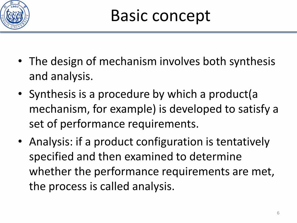
Basic concept
• The design of mechanism involves both synthesis and analysis.
• Synthesis is a procedure by which a product(a mechanism, for example) is developed to satisfy a set of performance requirements.
• Analysis: if a product configuration is tentatively specified and then examined to determine whether the performance requirements are met, the process is called analysis.
6

Tools available to the designer of linkage and other mechanisms
• Software selection • Animation: motion simulation
software -working model • Equation form: mathematics
software-Mathcad, math type ,etc. • Trigonometric functions: linkage
solutions- ANGLE or ARCTAN2 • User experience : particular
programming language- BASIC,FORTRAN, C++,etc.
7
Digger model in Working model 2 D
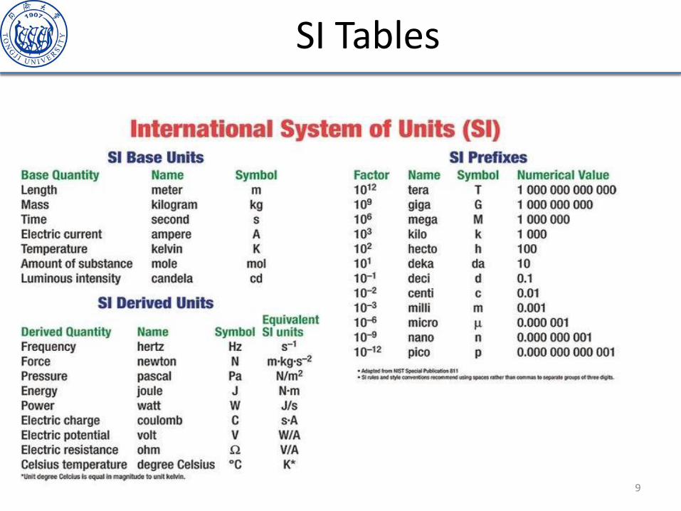
Systems of units
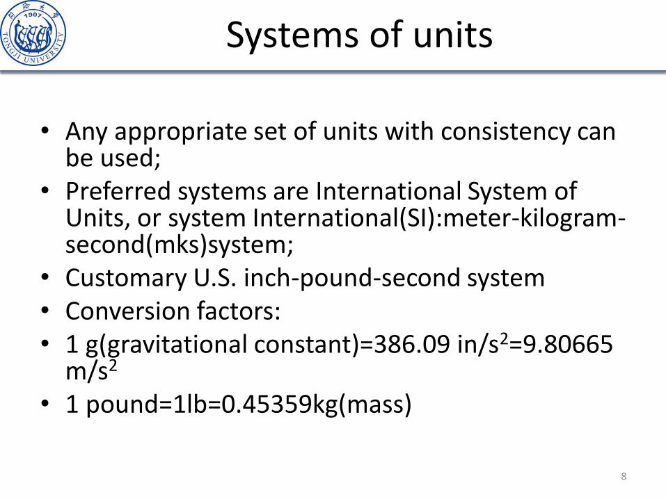
• Any appropriate set of units with consistency can be used;
• Preferred systems are International System of Units, or system International(SI):meter-kilogram-second(mks)system;
• Customary U.S. inch-pound-second system • Conversion factors: • 1 g(gravitational constant)=386.09 in/s2=9.80665
m/s2
• 1 pound=1lb=0.45359kg(mass)
8
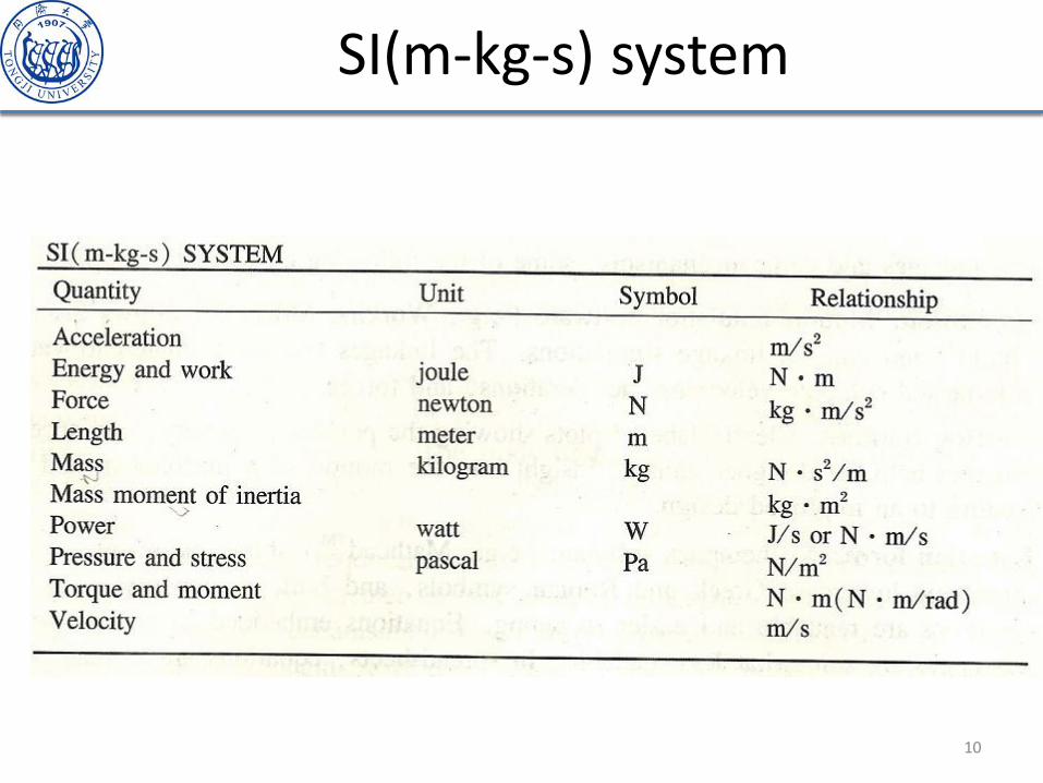
SI(m-kg-s) system
10
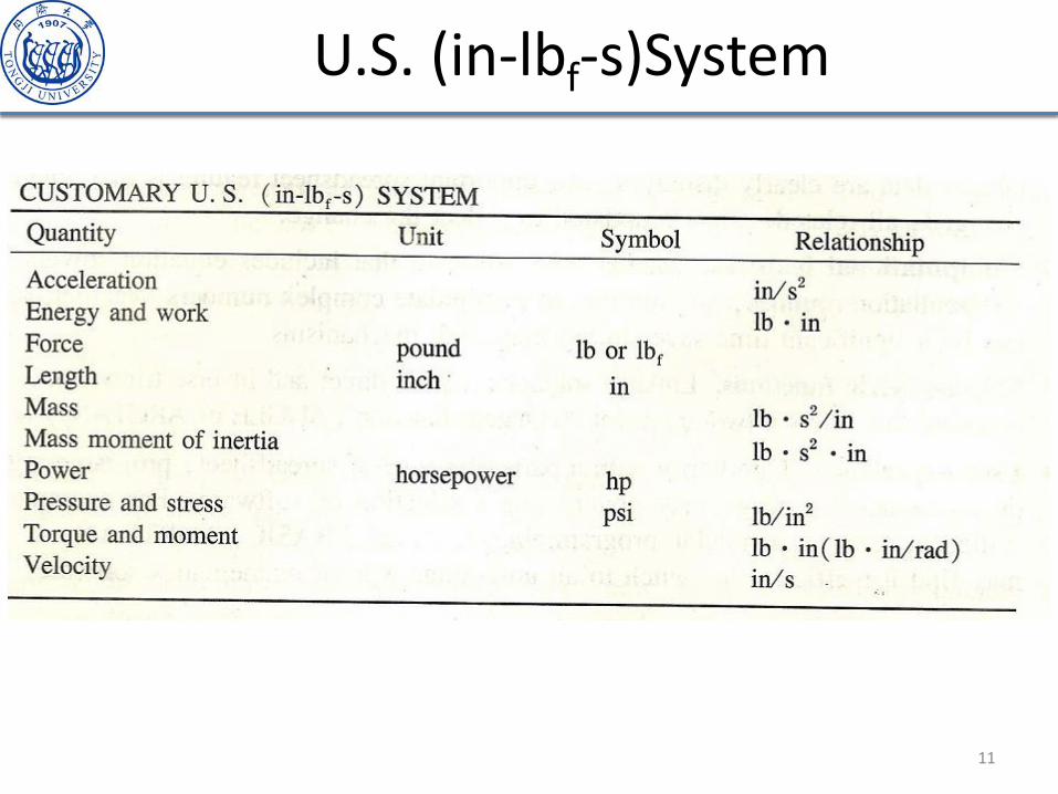
U.S. (in-lbf-s)System
11
1.4 Terminology and definitions
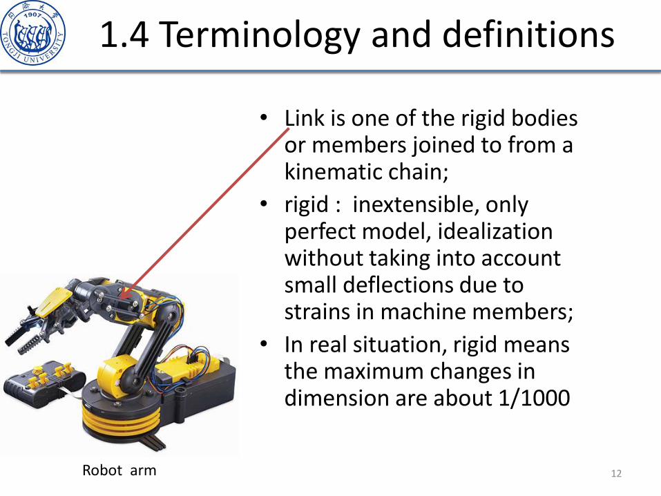
• Link is one of the rigid bodies or members joined to from a kinematic chain;
• rigid : inextensible, only perfect model, idealization without taking into account small deflections due to strains in machine members;
• In real situation, rigid means the maximum changes in dimension are about 1/1000
12 Robot arm

Terminology and definitions(continue)
• Frame: the fixed or stationary link in a mechanism is called the frame.
• Example: in an automotive engine, the engine block is considered the frame.
13
Air-cooled boxer engine on a 1954 BMW motorcycle
Four-stroke cycle 1. Intake 2. Compression 3. Power 4. Exhaust
frame

Two-stroke engine
• A two-stroke, or two-cycle, engine is a type of internal combustion engine which completes a power cycle in only one crankshaft revolution and with two strokes, or up and down movements, of the piston in comparison to a "four-stroke engine", which uses four strokes. This is accomplished by the end of the combustion stroke and the beginning of the compression stroke happening simultaneously and performing the intake and exhaust (or scavenging) functions at the same time.
• high power-to-weight ratio, reduced number of moving parts, more compact and significantly lighter.
14
A two-stroke engine, in this case with an expansion chamber illustrates the effect of a reflected pressure wave on the fuel charge. This is essential for maximum charge pressure (volumetric efficiency) and fuel efficiency. It is used on most high-performance engine designs.

Joint
• Joint or Kinematic Pair : the connections between links that permit constrained relative motion are called joints.
• Revolute joint or a pin joint : the joint between a crank and connecting rod, one degree of freedom;
• Sphere joint : ball joint, three degree of freedom;
15

Joint
16

Lower and Higher Pairs
• Connections between rigid bodies consist of lower and higher pairs of elements.
• Lower Pairs : surface contact between two rigid bodies;
• Higher Pairs: point or line contact between rigid bodies;
17

Common linkage joints
18
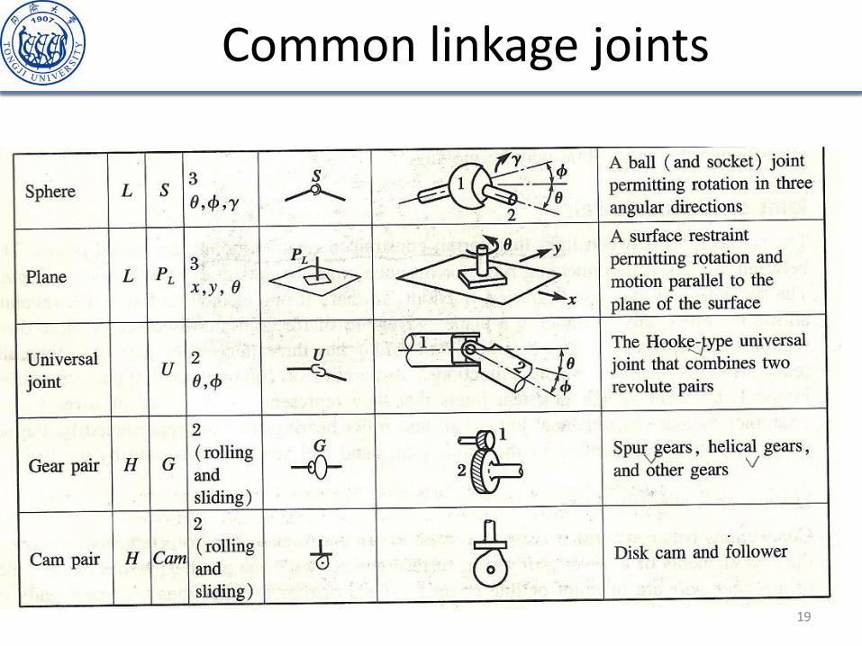
Common linkage joints
19

Closed-loop kinematic chains
• A kinematic chain is an assembly of links and pairs(joint);
• Each link in a closed-loop kinematic chain is connected to two or more other links.
20
Four bar linkage

Open-loop kinematic chains
• One or more of links connected to only one link.(e.g. robot arm)
21
ASIMO(Advanced Step in Innovative MObility
) (28 April 2011)
Manufacturer Honda
Year of creation
2000 Welding robot

Manipulators
• Manipulators designed to simulate human arm and hand motion. An typical example of open kinematic chain.
• Typical manipulator consists of a supporting base with rigid links connected in series, the final link containing a tool or a “hand”.
• It is an arm-like mechanism that consists of a series of segments, usually sliding or jointed, which grasp and move objects with a number of degrees of freedom.
22

Robots
• Robot=Programmable manipulator= manipulator + programmable controller
• Follow a sequence of steps directed by a computer program;
• Robot can be retooled, and reprogrammed for a variety of tasks;
• Typical application: spray painting, assembling parts, and welding;
23

Linkage
• A mechanical linkage is an assembly of bodies connected to manage forces and movement.
• Linkage modeled as a network of rigid links and ideal joints is called a kinematic chain.
24
The deployable mirror linkage is constructed from a series of rhombus or scissor linkages
An extended scissor lift
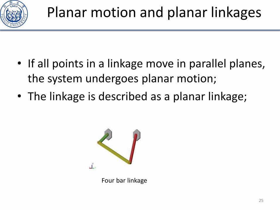
Planar motion and planar linkages
• If all points in a linkage move in parallel planes, the system undergoes planar motion;
• The linkage is described as a planar linkage;
25
Four bar linkage

Spatial motion and spatial linkages
• The more general case in which motion cannot be described as taking place in parallel planes is called spatial motion , and the linkage is called a spatial or three-dimension(3D) linkage.
26

Inversion
• The absolute motion of a linkage depends on which link is fixed-that is , which link is selected as the frame.
• If two otherwise equivalent linkages have different fixed links, then each is an inversion of the other.
27
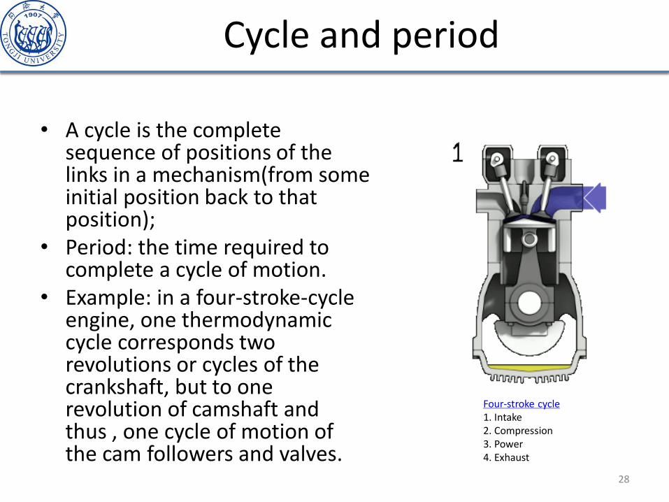
Cycle and period
• A cycle is the complete sequence of positions of the links in a mechanism(from some initial position back to that position);
• Period: the time required to complete a cycle of motion.
• Example: in a four-stroke-cycle engine, one thermodynamic cycle corresponds two revolutions or cycles of the crankshaft, but to one revolution of camshaft and thus , one cycle of motion of the cam followers and valves.
28
Four-stroke cycle 1. Intake 2. Compression 3. Power 4. Exhaust

29
The six degrees of freedom of movement of a ship.
Attitude degrees of freedom for an airplane
1.5 Degrees of Freedom(DOF)

1.5 Degrees of Freedom(DOF)
• The number of degrees of freedom of a linkage is the number of independent parameters we must specify to determine the position of every link relative to the frame or fixed link;
• The number of degree of freedom of a linkage may also be called as the mobility of the linkage;
• If the instantaneous configuration of a system may be completely defined by specifying one independent variable , that the system has one degree of freedom.
• Most practical mechanisms have one degree of freedom; • An unconstrained rigid body has six degrees of freedom:
translation in three coordinate
30

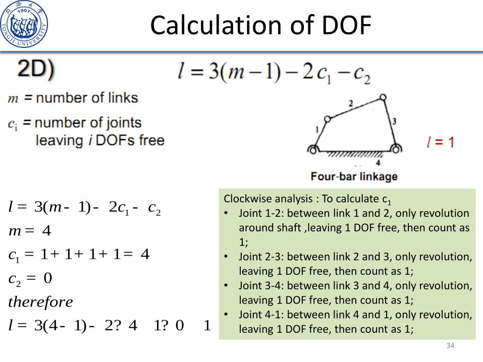
Calculation of DOF
31

Example
32

Calculation of DOF
33
1 2
1
2
3( 1) 2
4
1 1 1 1 4
0
3(4 1) 2 4 1 0 1
l m c c
m
c
c
therefore
l
= - - -
=
= + + + =
=
= - - ? ?
Clockwise analysis: To calculate c1 • Joint 1-2: between link 1 and 2, only revolution
around shaft ,leaving 1 DOF free, then count as 1;
• Joint 2-3: between link 2 and 3, only revolution, leaving 1 DOF free, then count as 1;
• Joint 3-4: between link 3 and 4, only revolution, leaving 1 DOF free, then count as 1;
• Joint 4-1: between link 4 and 1, only straight sliding, leaving 1 DOF free, then count as 1;
Calculation of DOF
34
1 2
1
2
3( 1) 2
4
1 1 1 1 4
0
3(4 1) 2 4 1 0 1
l m c c
m
c
c
therefore
l
= - - -
=
= + + + =
=
= - - ? ?
Clockwise analysis : To calculate c1 • Joint 1-2: between link 1 and 2, only revolution
around shaft ,leaving 1 DOF free, then count as 1;
• Joint 2-3: between link 2 and 3, only revolution, leaving 1 DOF free, then count as 1;
• Joint 3-4: between link 3 and 4, only revolution, leaving 1 DOF free, then count as 1;
• Joint 4-1: between link 4 and 1, only revolution, leaving 1 DOF free, then count as 1;

Calculation of DOF
35
1 2
1
2
3( 1) 2
4
1 1 1 1 4
0
3(4 1) 2 4 1 0 1
l m c c
m
c
c
therefore
l
= - - -
=
= + + + =
=
= - - ? ?
Assumption: 1, revolute clockwise; 2,upper belt is tensioning, therefore
rigid; 3,down belt can be neglected;4, belt & pulley rigid body & rigid body revolution joint; Clockwise analysis : To calculate c1 • Joint 1-2: between link 1 and 2, only revolution around shaft ,leaving 1
DOF free, then count as 1; • Joint 2-3: between link 2 and 3, only revolution, leaving 1 DOF free,
then count as 1; • Joint 3-4: between link 3 and 4, only revolution, leaving 1 DOF free,
then count as 1; • Joint 4-1: between link 4 and 1, only revolution, leaving 1 DOF free,
then count as 1;
Drive pulley driven pulley

Calculation of DOF
36
1 2
1
2
3( 1) 2
3
1 1 2
1
3(3 1) 2 2 1 1 1
l m c c
m
c
c
therefore
l
= - - -
=
= + =
=
= - - ? ?
Assumption: revolute anticlockwise; Clockwise analysis : To calculate c1 • Joint 2-3: between link 2 and 3, only revolution, leaving 1 DOF free,
then count as 1; • Joint 3-1: between link 3 and 1, only revolution, leaving 1 DOF free,
then count as 1; To calculate c2 • Joint 1-2: between link 1 and 2, tangential translation and normal
translation marked as Vt and Vn at contacting point P;
Vt Vn
P

Cam system overview
37

Example
38
1
2 3 4
5
6 7
8
1 2
1
2
3( 1) 2
8
1 1 1 1 1 1 1 1 1 9
0
3(8 1) 2 9 1 0 3
l m c c
m
c
c
therefore
l
= - - -
=
= + + + + + + + + =
=
= - - ? ?
• 2D, planar motion • Number of revolution joint is 9,c1=9; • Non joint leaving 2 freedom, C2=0; • Conclusion : l=3 means that at least
3 possible motion trajectories
R means Revolution joint

Example
39
R means Revolution joint, 1DOF S means Sphere joint,3 DOF P means Prism joint,1DOF
1 2 3 4 5
1
2
6( 1) 5 4 3 2
8
1 1 1 1 1 1 6
0
3 1 1 1 3
4 0
5 0
6(8 1) 5 6 3 3 42 30 9 3
l m c c c c c
m
c
c
c
c
c
therefore
l
= - - - - - -
=
= + + + + + =
=
= + + =
=
=
= - - ? ? - - =
1 2
3 4
5 6
7
8

Example
40
1 2
1
2
3( 1) 2
7
1 1 1 1 1 1 6
0
3(7 1) 2 6 1 0 6
l m c c
m
c
c
therefore
l
= - - -
=
= + + + + + =
=
= - - ? ?
• 2D, planar motion • Number of revolution joint is 6,c1=6; • Non joint leaving 2 freedom, C2=0; • Conclusion : l=6 means at least 6
possible motion trajectories
R means Revolution joint
1
2
3
4 5
6 7

Example
41 41
R means Revolution joint, 1DOF S means Sphere joint,3 DOF Conclusion : l=6 means at least 6 possible motion trajectories
1 2 3 4 5
1
2
6( 1) 5 4 3 2
5
1 1 1 3
0
3 1
4 0
5 0
6(5 1) 5 3 3 1 24 15 3 6
l m c c c c c
m
c
c
c
c
c
therefore
l
= - - - - - -
=
= + + =
=
=
=
=
= - - ? ? - - =
1
2
3
4
5

Example
42
Hydraulic straight cylinder=Prism
Revolution joint
R
R
R R
R
R
R
R
Prism joint
P
1 2
1 2
3( 1) 2
9, 9 2 11, 0
3(9 1) 2 11 1 0 2
l m c c
m c c
therefore
l
= - - -
= = + = =
= - - ? ?
tractor

Example
43
R
4
3
R
1
R
R 2
Welding robot arm
5
1 2 3 4 5
1
2
3 :
6( 1) 5 4 3 2
6
1 1 1 1 1 5
0
3 0
4 0
5 0
6(6 1) 5 5 30 25 5
D
l m c c c c c
m
c
c
c
c
c
therefore
l
= - - - - - -
=
= + + + + =
=
=
=
=
= - - ? - =
6
R

Example
44
Function:1,bear the load; 2,control the direction

Caution in analysis
45
In order to reduce wearing between 3 and 1, 2 equals a pin, so 2 can be neglected into a point contact
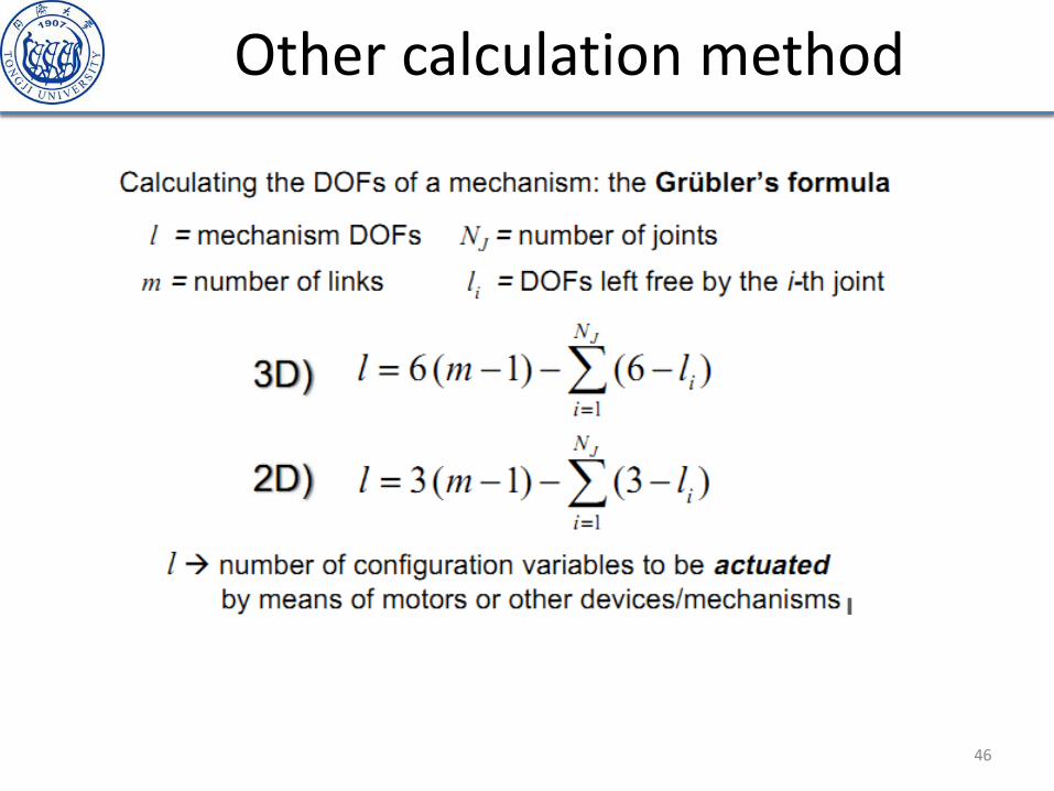
Other calculation method
46

Other calculation method
• In planar motion
47
3 2 L Hl n l l= - -
Number of kinetic links
Number of lower pairs
Number of higher pairs
Lower Pairs : surface contact between two rigid bodies; Higher Pairs: point or line contact between rigid bodies;

1.6 Classification of Closed Planar Four-bar linkages: the Grashof Criterion
• The Grashof condition for a four-bar linkage states: If the sum of the shortest and longest link of a planar quadrilateral linkage is less than or equal to the sum of the remaining two links, then the shortest link can rotate fully with respect to a neighboring link. In other words, the condition is satisfied if S+L ≤ P+Q where S is the shortest link, L is the longest, and P and Q are the other links.
• S+L ≤ P+Q
48
Types of four-bar linkages, s = shortest link, l = longest link

1.7 Limiting Positions of Slider-crank linkages
• The limiting positions(dead points) of a slider-crank define the stroke of the piston(slider);
• At limiting positions, the piston has zero velocity, but high acceleration;
• The general solution: depend on the inertia of the crank;
49
Four-stroke cycle 1. Intake 2. Compression 3. Power 4. Exhaust

1.8 Mechanisms for specific application
• Typical • Slider-crank mechanism : pump , compressor , internal-combustion
engine, etc. • Fluid links : force transmission ,hydraulic or pneumatic cylinder in
machine tools, tractor, etc.; • Gear trains: high speed, high power ratings, precise speed ratios ,
used in machine tools; • Power screw: convert rotational motion to rectilinear motion;
50
Operation diagram of a double acting cylinder
Internal-combustion engine
Two meshing gears transmit rotational motion.
DVD drive with leadscrew and stepper motor.

Mechanisms for specific application
• Differential screw: high-thrust, low-speed linear motion;
• One-way clutch: drives one direction only, but permit freewheeling if the driven side over-speeds the driver.
51
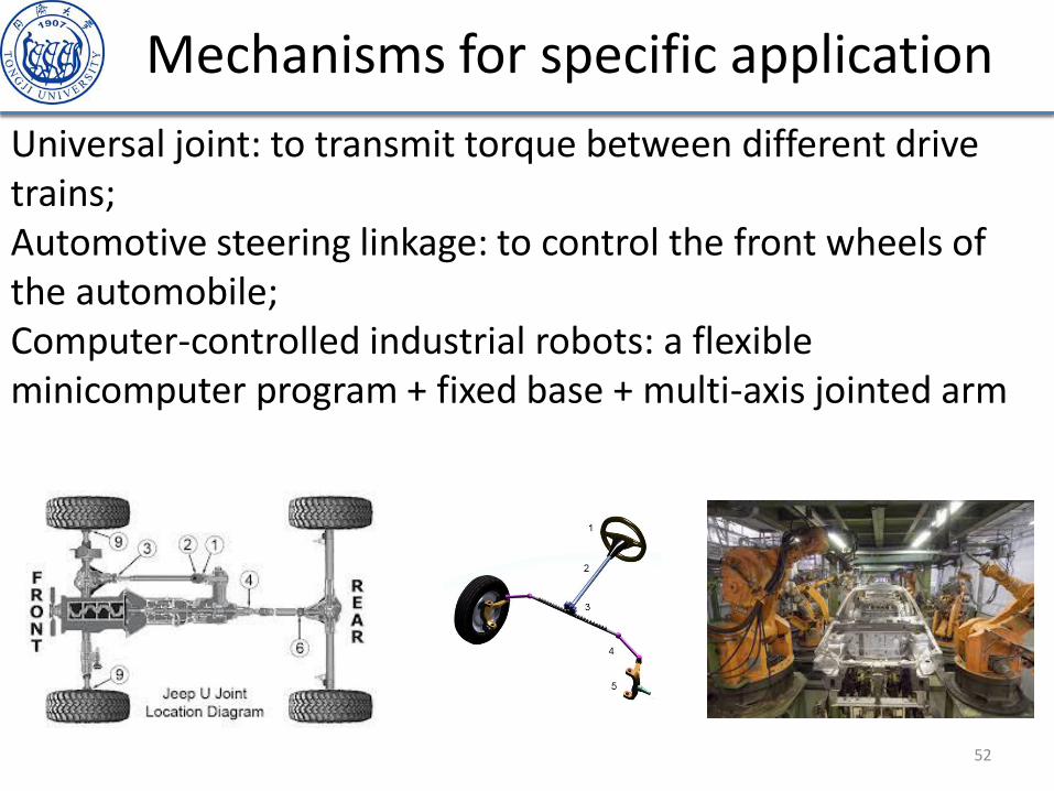
Mechanisms for specific application
52
Universal joint: to transmit torque between different drive trains; Automotive steering linkage: to control the front wheels of the automobile; Computer-controlled industrial robots: a flexible minicomputer program + fixed base + multi-axis jointed arm

1.9 Computer-aided linkage design
• Traditional design process: flowchart given by Sheth and Uicker(P. N. Sheth and J. J. Uicker, "IMP (Integrated Mechanisms Program), A Computer-Aided Design Analysis system for Mechanisms and Linkages," ASME Journal of Engineering for Industry, 94:454-464, 1972)
53
• New design approach-Concurrent engineering A portion of design process