Catalogo Escaleras
8
' Access Solutions... Ii r e _ .~~~~~~~~~~ 05 51 33/ACL BuyLine 1981 73? A 1 '6., -. ~~~~~~ -a--~~~~~Ik I nI I ,I~~ I/9 Elm Street * Manchester. NH U310UI '. . I ' - - - -L a 1 d,-- Tel. 603-668-1276 x19 * Fax 603-668-0678 __ ; ,' - " ' Il e-mail: [email protected] http://www.aclindustries.com r' SHIPYARD* CONSTRUCTION * RECREATIONAL MA-INE F ir i,. I. i- 1, l I
description
escaleras
Transcript of Catalogo Escaleras

'
Access Solutions...
Ii
re_ .~~~~~~~~~~
05 51 33/ACLBuyLine 1981
73? A1 '6.,-. ~~~~~~ -a--~~~~~Ik I nI
I ,I~~
I/9 Elm Street * Manchester. NH U310UI '. .I ' - - - -L
a 1
d,--
Tel. 603-668-1276 x19 * Fax 603-668-0678 __ ; ,' - " ' Ile-mail: [email protected] http://www.aclindustries.com r' SHIPYARD* CONSTRUCTION * RECREATIONAL MA-INE
F
ir
i,.
I.i-
1,
l
I
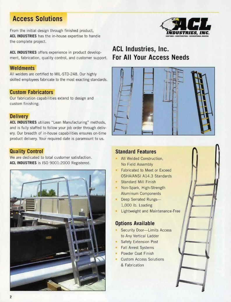
From the initial design through finished product,ACL INDUSTRIES has the in-house expertise to handlethe complete project.
ACL INDUSTRIES offers experience in product develop-ment, fabrication, quality control, and customer support.
All welders are certified to MIL-STD-248. Our highlyskilled employees fabricate to the most exacting standards.
Fl , F. ~i rs -WAl
Our fabrication capabilities extend to design andcustom finishing.
ACL INDUSTRIES utilizes "Lean Manufacturing" methods,and is fully staffed to follow your job order through deliv-ery. Our breadth of in-house capabilities ensures on-timeproduct delivery. Your required date is paramount to us.
We are dedicated to total customer satisfaction.ACL INDUSTRIES is ISO 9001:2000 Registered.
'- U'-
-- -
-a- w
-a- �.. �
SHIPYARDl CONSTRUCTION .RECRfATIONAL BRINE
ACL Industries, Inc.For All Your Access Needs
Standard Features* All Welded Construction,
No Field Assembly* Fabricated to Meet or Exceed
OSHA/ANSI A14.3 Standards* Standard Mill Finish* Non-Spark, High-Strength
Aluminum Components* Deep Serrated Rungs-
1,000 lb. Loading* Lightweight and Maintenance-Fi
Options Available* Security Door-Limits Access
to Any Vertical Ladder* Safety Extension Post* Fall Arrest Systems* Powder Coat Finish* Custom Access Solutions
& Fabrication
2
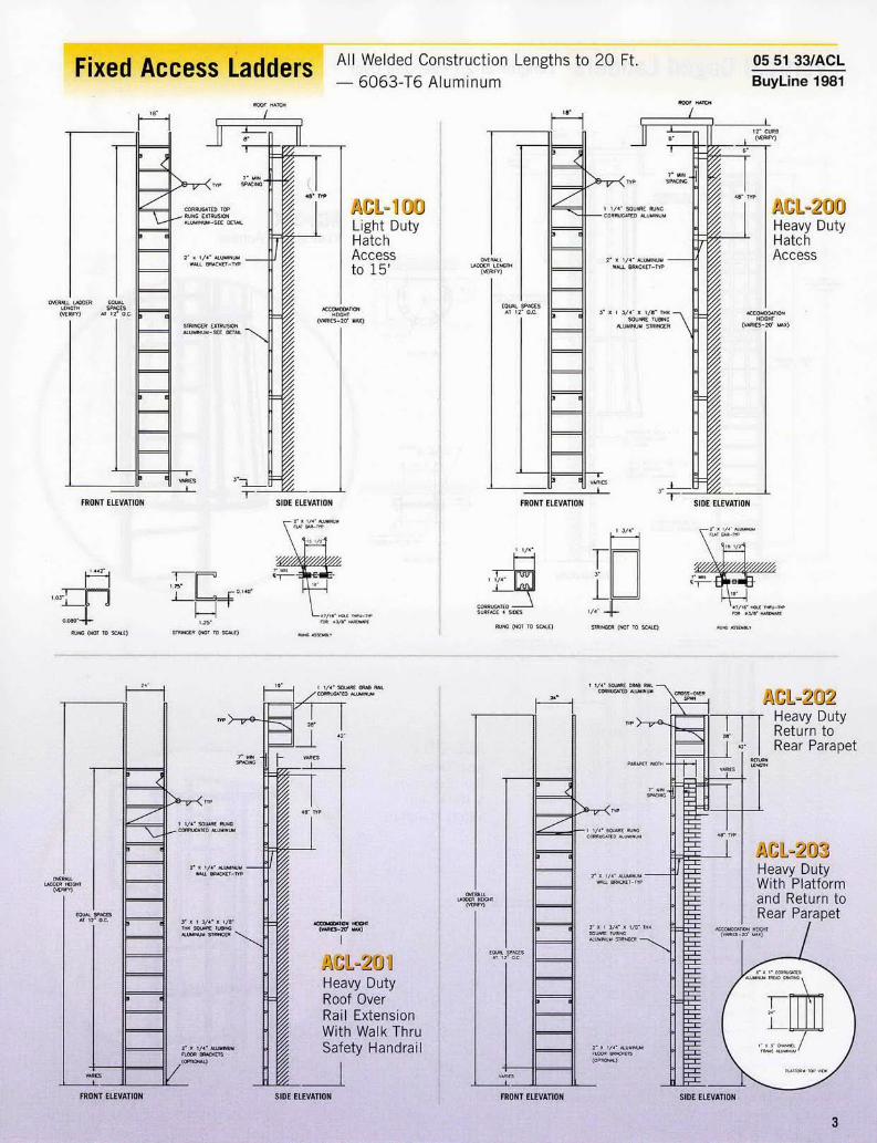
rKwdt F!3LS C WV1 L- iV[4 X3s All Welded Construction Lengths to 20 Ft.- 6063-T6 Aluminum
05 51 33/ACLBuyLine 1981
ACL-1 00Light DutyHatchAccessto 15'
ATAN
SIDE ELEVATION
i' Y 1/.' A -SU
FOR .J/l'_E
AT.
1ty
visionk Thruindrail
SIDE ELEVATION
MUE
R)L
EDLIAL. .ACES
s'i
I
I 0
2- Y-C,
2 L.
&lU'
-.R
FRONT ELEVATION
EORRUDATE*ARTACE A 9AES I/C
RUAD HAOT T SCALE) STRINER (WT TO SCALE)
F
I I 1
1 1
FRONT ELEVATION
I H
I H
MOOTF CAT
NEEN C
CR RUN HRALNG
2'.IN E$MiN
-rT--AES
LQOER EDTHIT SR-IT) AT T,
-J
1AMA)
FRONT ELEVATION
I 5W01 '
I 1- -t'
S-O$ HH - .E (MA TA HAUL )
SIUL LELEVAIUO
M"l
r AN.
il 1 T/-' SMUASH S- 2- YAATED ALUM
SM S ,AS SCY
11 r.,/,- y
' Y/' AWISALUMR CCTA
/ (1
RAU
-7-
FRONT ELEVATI O
FRONT ELEVATION SIOE ELEVATION
3
RO1 ..TC.
II
_.0.. 1 1LENRC, lw
.-
I I
I t ._ z
*UP
OVEI.IEI
-Roe
�- . 1/�- A--- -- p
qI
-v
1.0,
-C,
WNG (NOT TO SCkE)

I Lengths of 20 Feet and Over
ACL-3M)Roof Hatch Access
FRONT ELEVATION SIDE ELEVATION
7 i
, I
ACL301Roof OverRail Extension& Walk ThruSafety Handrail
FRONT ELEVATION SIDE ELEVATION
I, o.A
lSiF 9:TtSt
CGi TUW IT
4

iA¶!~ ' 3 ji d L oi | Lengths of 20 Feet and Over05 51 33/ACLBuyLine 1981
I ,i SOW BRAS R.
FRONT ELEVATION SIDE ELEVATION Platform Over Parapet andReturn to Rear Parapet Ladder
-390mediateormRoofRail
ths of 30 Feet and Over)
5
-
-_J% 13

ACL-502Ship Ladder-Hatch Access
ACL-501Ship Ladder-Standardwith Handrail
ACCOMODATIONHEIGHT
(VAR ES)
6' X 2' CHANNELSTRINGER ALUMINUM
6E X 1 3/4" TREAD-CORRUGATED SURFAC
ALUMINUM-mTP
Standard Features* All Welded Construction,
No Field Assembly* Treads Bolt On for
Ease of Replacement* Finish-Mill Finish* High Strength 6063-T6 Alloy* Safety Treads Type SN6,
Non-Slip Serrated
Options Available* Safety Tread-Type SNAT6 Available,
Abrasive Filled for Long-LastingNon-Slip Use
* Custom Designs to Suit All Applications* Models 501 and 505 - Also Available
for Hatch Access6
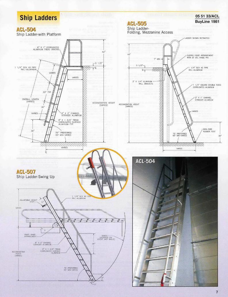
ACL-504Ship Ladder-with Platform
ACL-505Ship Ladder-Fold ing, Mezzanine Access
05 51 33/ACLBuyLine 1981
75
ACCt
rlpa Sr f&ffi n !ts LbAurs ; rg i A->SyWC i h,'M t k. L |ritW FPART 2 -PRODUCTS2.1 ACCEPTABLE MANUFACTURERS
A. ACL mdustries Inc 179 Elm Street, Manchester,New Hampshire 03101: 603-668-1276.
B. Manufacturers of equivalent products submitted andapproved in accordance with Section 01630 -ProductSubstitution Procedures.
2.2 MATERIALS
A. Exdruded aluminum: ASTM B22, Alloy 6063 TemperT 6, non-spark
B. Sheet aluminum: ASTM B209 6063 TemperT-6.Standard access /adder finish is mill finished aluminum.Electrostatically applied powder paint color coatings can bepnvided as a special order Contact ACL Industries, Inc. forreformation and assistance in specitabog this special finish.
C Finish Mill finished aluminum.
2.3 GENERAL FABRICATIONA. Field verity ladder dimensions pr/onto fabocation.B. Fabr ate to designs indicated on Drawings and to meet
performance requirements specified in Paragraph 14C. Components shall be welded. Ladder shall not require
field assembly
2.4 VERTICAL FIXED ACCESS LADDERAC In dusetres Intc manufacturers 5 models of beed, meal mounted,ernical access ladders Selectnequitd/type hfom the followingoptons and delete nor-applicable options
A. Type Fixed, wall mounted, vertical, aluminum, [lightduty. hatch access adder. Model No. ACL-10t] [heavyduty, hatch access; Model No ACL 2001 [heavy duty, cotoser rail extension ladder; Model No ACL-2101 [heavyduty, return to rear of parapet ladder; Model No. ACL-202] [heavy duty with platform and return to rear ofparapet ladder; Model No. ACL-203] as manufactured byACT Industries, Inc.
Include the following paragraphs to specify light duty hatchaccess ladder Model ACL -lDa This model Is used for heightsup 20 feet maximum and is mounted with side rodis 3 inchesahove finish floor
B. Nomina height: IT feet.] [As indicated seDrawings.]
C. Side rails 1-3/4 inches wide by 1-1/4 inches deepchannels with 0140 inch wall thickness.
Standard rungs for vertical fixed access ladders ame 18 and 24inches long Contact ACL Industries, Inc. for other lengths avdil-able as special orders
D. Rungs: 103 inches wide by 1442 inches deep chan-nels with 0D080 inch wall thickness by 1t1] [241 incheslong with serrated surfaces and capable of 1,000pounds load Space 12 inches on center Attach rungsin centerline of side rails by weld ng
Include the forowing paragraphs to specify heavy duty hatchaccess ladder Model AC -200 This model is used for heightsup 20 feet maximum and is mounted wdh side rails 3 inchesabove finish floor
B. Nominal height; [[I W teat.] [As indicated ohDrawings.]
C. Side rails: 1-3/4 inches by 3 inches tubes with 1/8 inchwall thickness.
Standard rungs for vertical fixed access ladders are dA and 24inches tong Contact ACt Industrmes, Inc. forother lengths avail-able as special orders
D. Rungs: 1-114 wide by 1-1/4 inches tube by [181 [24]inches long with corrugated surfaces and capable of1,000 pounds load, Space 12 inches on center. Attachrungs in centerline of side rails by weld ng.
Include the following paragraphs to specify heovy duty ntf overrad extension ladder Model ACt-201 Fhis model is used forheights up 20 feet maximum and may be mounted with siderails 3 inches above finish floor or with side rails anchored toPoor with brackets
BA Nominal height [f t feat.] [As indicated onDraw ngs.]
C. Side rails: 1-3/4 inches by 3 inches tubes with tAT inch wallthickness. EAtend rails 42 inches above [root line.] [parapet.]
D. Extension At top of side rails provide 19 inches exten-sions 28 inches high, constructed from 1-1/4 inchessquare tube grab bars with corrugated surfaces.
Standard rungs for vertical fixed access ladders am 18 and 24inches long Contdct ACL Industries, Inc. for other lengths avadable as special orders
E, Rungs: 1-1/4 inches square tube by [18] [24] incheslong with corrugated surfaces and capable of /1,10pounds load Space 12 inches on center. Attach rungsin centerline of side rails by welding.
Include the following paragraphs to speciot heavy duty return tomearof parapetladder ModelACL-202. This modetrosused for
heights up 20 feet maximum and may be mounted with siderails 3 inches above finish floor or with side eils anchored toloor with brackets.
B. Nominal height: [LI l feet] [As indicated onDrawings].
Cmoss over span will be determined by width of parapet wha
C Cross over span; [I inches.] [As indicated onDrawings.]
D. Side rails: 1-3/4 inches by 3 inches tubes wdh 1/8 inchwall thickness ELtend rails 42 inches above parapet.Pmvide rails on opposite side mounted to rear of para-pet and extending 42 inches above parapet and belowparapet to roof line
E. Grab bars: Connect front and wear side rails with 4pairs of 1-1/4 inches square tube grab bars with corou-gated surfaces
Standard rungs for vertical fixed access ladders am 18 and 24inches long Contact ACt Industries, Inc for other lengths avail-able as special orders
F. Rungs 11/4inches square tube by [18] [24] incheslong with corrugated surfaces and capable of 1,000pounds sad. Space 12 inches on center Attach rungsin centerline of side rails by welding
Include the following paragraphs to specify heavy duty wthplatorm and return to marof parapet ladder ModeIACT-203This model is used forheights up 20 feet maximum and may bemounted with side rails 3 inches above finish floor or with sodatais anchored to floor with brackets,
B. Nominal height: [FI feet] [As indicated onDrawings.]
Cross over span will be determined by width ofparapet wal
C Cross over span: [I 1 inches.] [As indicated onDrawings.]
D Side rails: 1-3/4 inches by 3 inches tubes with 1/8 inchwall thickness Extend rails 42 inches above parapet.Provide rails e opposite side mounted to rear of para-pet and eWtending 42 inches above parapet and belowparapet to roof line
E. Grab bars: Connect f/ont and rear side rails with 4pairs of 1-1/4 inches square tube grab bars wlh comru-gated surfaces
F Platform Provide cross over platform fabricated from 6inches wide by 1-3/4 inches deep aluminum treads withcorrugated surface.
Standard rungs for vertical fixed access ladders are 18 and 24inches long ContactACt Industoes, Inc for otherlengths avafl-ad/e as special orders
G. Rungs 1-1/4 inches square tube by [It] [24] incheslong with corrugated surfaces and capable of 1,000pounds load. Space 12 inches on center Attach nungsin centerline of side rails by welding.
2.5 ACCESSORIESA. Supponr brackets:
1. Wall brackets Supportladder at top and bottom andat 4/ inches maximum intermediate points wdth 2 by1/4 inch minimum flat bar aluminum wall brackets.Allow 7 inches minimum clearance from wal to cen-ter line of rungs.
As an option, side rails may be anchored to floor with brackets.Include the following paragraph for this option
2. Floor brackets: Anchor s de rails to floor with 2 by1/4 inch minimum flat bar aluminum floor bracketsAllow 7 inches minimum clearance trom wall to cen-ter line of rungs.
As an option, a hinged security door can be provided to coweebottom ladder rungs and prevent unasuthorized roof access.Include the following paragraph for this option
B. Security door: Provide hinged security doorto coverbottom rungs and prevent unauthotined root access.1. Construction: Fabricate /rom 11 gage flat aluminum
sheet cover ng front of ladder Provide side flangesextending toward wall and meeting aluminum flangemounted to wall.
2. Equip door with continuous stainless steel hinge andpadlock hasp
Safety post exension can be provided in conjunction with rofhatch and specified in othersections. As s option, safety postextension can be provided by ACt Industries Inc with accessladder Include the following paragraph to specify this option
C. Safety post extension Post extension for fixed laddersconstructed of tubular alum num sections with adjustablemm int g brackets for attachment to top of ladder1. Operation: Upward and downward movement con-
trolled by spring balanc ng mechanism activated byrelease rod Automatically locks when fully extended.
2. Permanently mount operating instructions on safetypost to be plainly visible to ladder users.
PART 2 -PRODUCTS
2.1 ACCEPTABLE MANUFACTURERSA ACL Industries Inc 179 Elm Street Manchester, New
Hampshire 03101; 60366861276B. Manufacturers of equivalent products submitted and
approved in accordance with Section 01630 -ProductSubstitution Procedures.
2.2 MATERIALSA. E/rudedaluminum ASTIB221, Alloy,6063fTemperT-6,
non-sparkB. Sheet aluminum: AS/M B209 6063 Temper T-6A
Standard access ladder finish is mill finished aluminum.Electroststically applied, powder paint color coatings can be pro-vided as a special order Contact ACt Industries, Inc for iner-oation and assistance in specifying this special finish
C. Finish Mill finished aluminum
2.3 GENERAL FABRICATIONA Field verify ladder dimensions pnor to fabrication.B. Fabricate to designs indicated on Drawings and to meet
performance requirements specified in Paragraph 1.4.C Components shal be welded and bolted. Ladder shall
not require field assembly
2A INCLINED SHIP LADDERACt Industries, Inc manufacturers 6 models of rochned ship lad-der Select required type from the following options and deletenon-applicable options.
A. Type: Fieed, inclined, aluminum, [standard ship ladderwith handra 1: Mode No. ACL 501] [ship ladder with roothatch access; Model No ACL-502L [ship ladder withcross ov mer access Model No ACL-5031 [ship ladderwith platform; Model No ACL-504] [folding mezzanineaccess ship ladder: Model No. ACL 505] [counterbal-anced swing down ship ladder; Mo del ACL-507] as man-ufactured by ACL Industries Inc.
B Accommodation height: [I feet.] [As indicated onDrawings.]
Preferred angle of icnaboti Is 75 degrees. Minimum anglf is60 degrees.
C. Angle of inclination: F. 1 degrees.] [As indicated onDrawings
Standard tread is a 6 inches wide by 1-34 inches deep aluminumchannel shaped section with comrugated surface An optional 6 by1-3d4 inches alummum, abrasive filled tread is available Otheroptions include 4and inches wide treads 1-1d/ byd -1/4 inch-es corrugated tubular rungs are used for t/eads for folding meam-nine access ship ladder Model ue ACt 505. Delete the followingparagraph if Model uo ACt-505 is being specified
D Treads [6] F inches w de by 1/3-4 inches deepby 24 inches wide aluminum channel shaped sectionwdh [corrugated surface.] [abrasive filled corrugations.]1. Equally space treads as indicated on Drawings and
reviewed shop drawings2. Connect treads to stringers with bolts to allow for
future replacementInclude the following paragraphs tospecify standard shipladderwmh handrail Model flu ACt-501.
E. Stringers: 6 by 2 inches aluminum channel.E Handrail: Fabricate from 1-1/4 inches diameter alu-
minum pipe1. Form returns with 6 inches radius.2. Attach rail to stringer with pipe sections spaced at
approximately 30 inches such that rail projectsapproximately 6 oches above stringer
3. Locate boom of handrail 36 inches above floor4 Ertend rail above ladder such that top of rail is 42
inches above roof levelInclude the following paragraphs to speci, ship ladder wih arofhatch access, Model fol AC3-502
E. Stringers: 6 by 2 inches aluminum channel.
EHandrail: Fabricate from 1-11/4 inches diameter alu-minum pipe1. Form returns with 6 inches radius.2. Attach rail to stringer with pipe sections spaced at
approximately 30 inches such that rail projectsapproximately 6 inches above str nger
3 Extend rail above ladder such that top s/ rail isapproximately 6 inches above top tread and berowroof hatch door
4 Locate bottom of handrail 36 inches above flor.Include the following paragraphs to specify ship ladder withcross over access, Model /o ACt-503
E. Configuration: Two opposing inclined ladders connectedby cross over platform as shown on Drawings andreviewed shop drawings,1. Distance between base of opposing ladders: ] Iinches.] [As indicated on Drawings.]
2. Cross over span: F I inches.] [As indicated onDrawings.]
FStringers 6 by 2 inches aluminum channel. Top ofopposing stringers shall be connected with 6 by 2 incheschannel wh ch forms support for platform
G. Platformr Provide cross over platform at top of ship lad-der fabricated fram 6 inches wide by I inch deep alu-minum treads with corrugated surface.
H. Railings: Fabricate handra I and guardrail from 1-1/4inches diameter aluminum pipe to configuration shownon Drawings and reviewed shop drawings.
1. Form returns with 6 inches radius2. Provide42 inches high guardrail on either side crass
over platform.3. Attach rail to stringer with pipe sections spaced at
approximately 30 inches such that rail projects apprni-mately 6 inches above stringer
4 Extend rai above ladder such that rail intersects andjoins top of guandra 1.
5. Locate bottom of handrail 36 inches above fltr.include the following paragraphs tospecfy/ ship ladder wth plaT-form; Model/in ACl 504d
E Stringers 6 by 2 inches aluminum channel. Top ofstringers shall return horizontally [ inches to walland form support for platform.
E Platform: Provide 24 inches wide by F incheslong platform at top of ship ladder fabricated trom 6inches wide by 2 inches deep aluminum treads wmh cor-rugated surface.
G. Railings: Fabricate handrail and guardrail from 1-1/4inches diameter aluminum pipe to configuration shownon Drawings and reviewed shop drawings.1. Form returns with 6 inches radius2 Provide 42 inches high guardrail on eaher side of
platform.3. Attach rail to stringer with pipe sections spaced at
approximately 30 inches such that rail projectsapproximately 6 inches ab/ce stringer
4. Etend rail above ladder such that rail intersects andjoins top of guardrail.
5 Locate bo tom of handrail 36 inches above floor.Include the following paragraphs to spoo/fy olding mezzanineaccess ship ladder Model fo. ACt-505 In contrast to other shipladders, Model No. ACt-505 has square tube treads,
D. Treads Form with two I 1/4 inches square tubes by 24inches long with corrugated surfaces
1. Equally space treads as indicated on Drawings andreviewed shop drawings
2. Attach treads to stringers by welding.E. Operation Folding adder shall store against wall with
stringers in vertical position. Top of ladder shall pivotwith sliding hinge assembly with stainless steel pin toinclined use position.
FStringers: 3 by I rnI aluminum channel. Equip bottomof stringer with non-skid rubber foot Top of stringershal be supported by wal bracket fabricated from 3inches by 1/4 inch thick aluminum plate.
S. Handrail Fabricate /mm 1-1/4 inches diameter alu-minum pipe
1. Form returns with 6 inches radius2 Attach rail to stringer such that rail projects app/orX-
mate y 6 inches above stringer3. ELaend rail above ladder/to form guardrail extending 42
inches abovetop tread.5. Locate bottom of handrail 36 inches above floor
Include the following paragraphs to specify swing down counter-balanced ship ladder to provide access to upper floor or maa-nine, Model No ACl-507
E. Operation: Swing down ladder attached to upper [mez-zanine] [floor] structure with pivoting counterbalancedmechanism. Ladder shal store horizontal y and can beplaced in inclined access position with ps I rope.
F Stringers 6 by 2 inches a uminum channel Attach leadcounter weights to top sides of stringers Design laddersuch that stringers project above upper floor level whenladder is in inclined position. Equip stringer extensionswith safety chain guards.
G. Handrail Fabricate from 1-1/4 inches diameter alu-minum pipe1, Form returns wi/h 6 inches radius,2. Attach ra I to stringer such that rail projects 36 inch
es above treads when ladder is in inclined pos/ion.H. Operating mechanism: Pivoting hinged counterbalanced
mechanism attached to suppom structure with bracketsas detailed on approved shop drawings.
2.5 ACCESSORIESA. Support brackets: Support ship ladder wmi top wall
brackets and bottom floor brackets fabricated from 2 by1/4 inch minimum flat bar aluminum.
For Complete Specifications See Sweets.com or the Sweets CD-Rom.
HIPURlD .CONSTRUC11ON -REC1RAYIORIU MARIN
179 Elm Street * Manchester, NH 03101Tel. 603-668-1276 x19 * Fax 603-668-0678
e-mail: [email protected] http://www.aclindustries.com