Fondazione Banco Alimentare Onlus. Catalogo biglietti augurali Natale 2013
Upload
jose-antonio-sillerico-suarezCategory
view
225download
0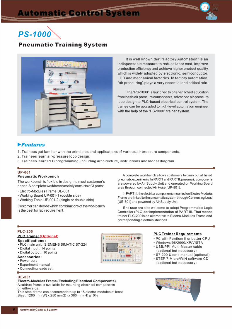
7/25/2019 Catalogo Banco Neumatico
http://slidepdf.com/reader/full/catalogo-banco-neumatico 1/96 Automatic Control System
Automatic Control System
PS-1000
Pneumatic Training System
• PLC main unit : SIEMENS SIMATIC S7-224• Digital input : 14 points
igital output : 10 points• D
PLC-200PLC Trainer (Optional)
Accessories :
Specifications :
• Power cord• Experiment manual• Connecting leads set
PLC Trainer Requirements
• PC with Pentium II or better CPU
• Windows 98/2000/XP/VISTA
• USB/PPI Multi-Master cable
(optional but necessary)
• S7-200 User’s manual (optional)
• STEP 7-Micro/WIN software CD
(optional but necessary)
Features
Electro-Modules Frame (Excluding Electrical Components) A cabinet frame is available for mounting electri cal compone nts
on either side.This steel frame can accommodate up to 15 electro-modules at least.Size : 1260 mm(W) x 250 mm(D) x 360 mm(H) ±10%
UE-001
UP-001Pneumatic Workbench
The workbench is flexible in design to meet customer's
needs.A complete workbench mainly consists of 3 parts:
Electro-Modules Frame UE-001
Working Board UP-001-1 (double side)
Working Table UP-001-2 (single or double side)
Customer can decide which combinations of the workbench
is the best for lab requirement.
•
•
•
A complete workbench allows customers to carry out all listed
pneumatic experiments. In PARTI and PARTII, pneumatic components
are powered by Air Supply Unit and operated on Working Board
area through connectedAir Hose (UP-801).
In PARTIII, the electrical components mounted on Electro-Modules
Frame are linked to the pneumatic system through Connecting Lead
(UE-501) and powered by Air Supply Unit.
End user are also welcome to adopt Programmable Logic
Controller (PLC) for implementation of PART III. That means
trainer PLC-200 is an alternative to Electro-Modules Frame and
corresponding electrical devices.
It is well known that “Factory Automation” is an
indispensable measure to reduce labor cost, improve
production efficiency and achieve higher product quality,
which is widely adopted by electronic, semiconductor,
LCD and mechanical factories. In factory automation,
“air pressuring” plays a very essential and critical role.
The “PS-1000” is launched to offer enriched education
from basic air pressure components, advanced air-pressure
loop design to PLC-based electrical control system. The
trainee can be upgraded to high-level automation engineer
with the help of the “PS-1000” trainer system.
1. Trainees get familiar with the principles and applications of various air pressure components.
2. Trainees learn air-pressure loop design.
3. Trainees learn PLC programming, including architecture, instructions and ladder diagram.
7/25/2019 Catalogo Banco Neumatico
http://slidepdf.com/reader/full/catalogo-banco-neumatico 2/97 Aut oma ti c C ont ro l S yst em
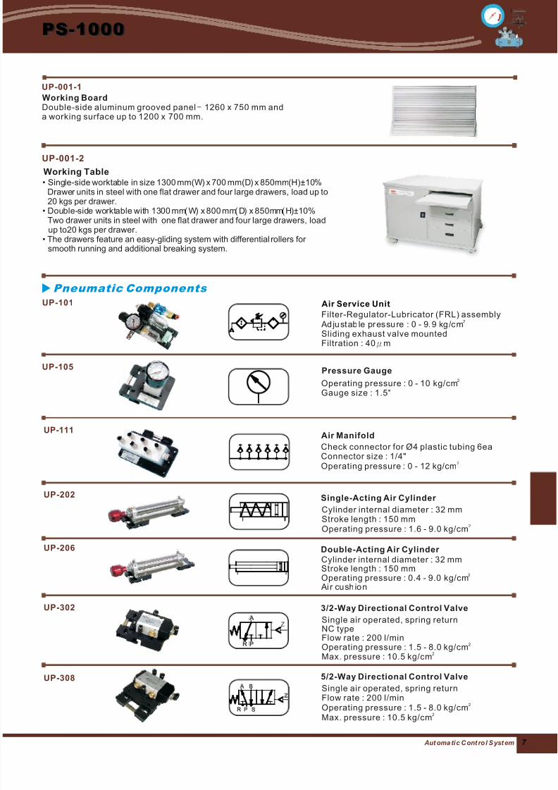
Operating pressure : 0 - 10 kg/cmGauge size : 1.5"
2
UP-105 Pressure Gauge
Check connector for Ø4 plastic tubing 6eaConnector size : 1/4"
: 0 - 12 kg/cmOperating pressure 2
UP-111Air Manifold
Single air operated, spring returnFlow rate : 200 l/minOperating pressure : 1.5 - 8.0 kg/cmMax. pressure : 10.5 kg/cm
2
2
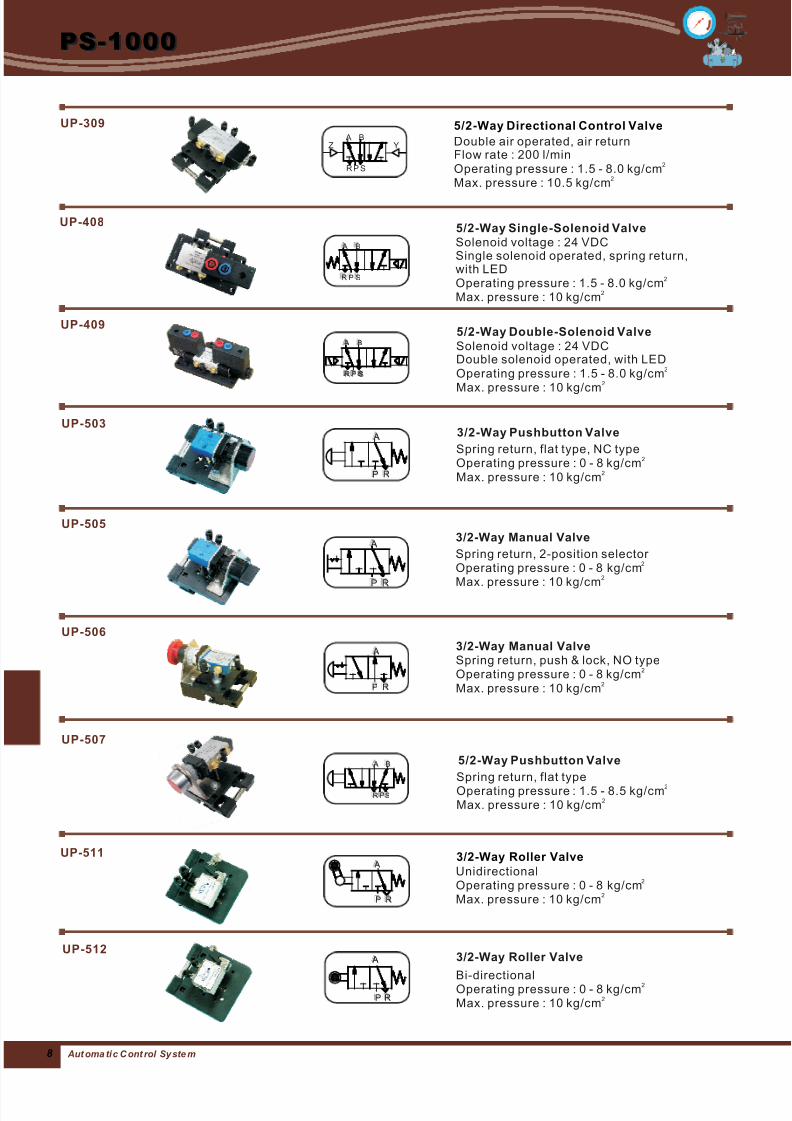
5/2-Way Directional Control Valve
Cylinder internal diameter : 32 mmStroke length : 150 mmOperating pressure : 1.6 - 9.0 kg/cm
2
UP-202 Single-Acting Air Cylinder
Cylinder internal diameter : 32 mmStroke length : 150 mmOperating pressure : 0.4 - 9.0 kg/cm Ai r cush io n
2
Double-Acting Air Cylinder
Single air operated, spring returnNC typeFlow rate : 200 l/minOperating pressure : 1.5 - 8.0 kg/cmMax. pressure : 10.5 kg/cm
2
2
3/2-Way Directional Control Valve
UP-308
UP-206
UP-302
Filter-Regulator-Lubricator (FRL) assembly Ad ju st ab le pr es su re : 0 - 9. 9 kg/c mSliding exhaust valve mountedFiltration : 40
2
μm
Air Service UnitUP-101
Pneumatic Components
PPR
A
A
RR PP SS
BB A
ZZ
Z
UP-001-2
Working Table• Single-side worktable in size 1300 mm(W) x 700 mm(D) x 850mm(H)±10%
Drawer units in steel with one flat drawer and four large drawers, load up to20 kgs per drawer.
• ( ) ( ) ( )±10%one flat drawer and four large drawers, load
up to20 kgs per drawer.• rollers for
smooth
Double-side worktable with 1300 mm W x 800 mm D x 850mm HTwo drawer units in steel with
The drawers feature an easy-gliding system with differentialrunning and additional breaking system.
Working BoardDouble-side aluminum grooved panel 1260 x 750 mm anda working surface up to 1200 x 700 mm.
–
UP-001-1
PS-1000
7/25/2019 Catalogo Banco Neumatico
http://slidepdf.com/reader/full/catalogo-banco-neumatico 3/98
PS-1000
Aut oma ti c C ont rol Sy ste m
Solenoid voltage : 24 VDCDouble solenoid operated, with LEDOperating pressure : 1.5 - 8.0 kg/cm
Max. pressure : 10 kg/cm
2
2
5/2-Way Double-Solenoid Valve
Spring return, flat type: 1.5 - 8.5 kg/cm
Max. pressure : 10 kg/cmOperating pressure 2
2
5/2-Way Pushbutton Valve
Spring return, flat type, NC typeOperating pressure : 0 - 8 kg/cmMax. pressure : 10 kg/cm
2
2
3/2-Way Pushbutton Valve
Spring return, 2-position selector Operating pressure : 0 - 8 kg/cmMax. pressure : 10 kg/cm
2
2
3/2-Way Manual Valve
Spring return, push & lock, NO typeOperating pressure : 0 - 8 kg/cmMax. pressure : 10 kg/cm
2
2
3/2-Way Manual Valve
UP-507
UP-505
UP-506
SSPR
A A BB
R
RP
A
A
RRP
A A
A A
RRP
P
PR SS
A
A B
B
UP-503
UP-409
Bi-directionalOperating pressure : 0 - 8 kg/cmMax. pressure : 10 kg/cm
2
2
UP-5123/2-Way Roller Valve
UnidirectionalOperating pressure : 0 - 8 kg/cmMax. pressure : 10 kg/cm
2
2
3/2-Way Roller ValveUP-511
PP RR
A A
PP RR
A A
Solenoid voltage : 24 VDCSingle solenoid operated, spring return,with LEDOperating pressure : 1.5 - 8.0 kg/cmMax. pressure : 10 kg/cm
2
2
UP-4085/2-Way Single-Solenoid Valve
SS
BB A
RR PP
Double air operated, air returnFlow rate : 200 l/minOperating pressure : 1.5 - 8.0 kg/cmMax. pressure : 10.5 kg/cm
2
2
5/2-Way Directional Control ValveUP-309
PR S
B A
Z Y
7/25/2019 Catalogo Banco Neumatico
http://slidepdf.com/reader/full/catalogo-banco-neumatico 4/99 Aut oma ti c C ont ro l S yst em
PS-1000
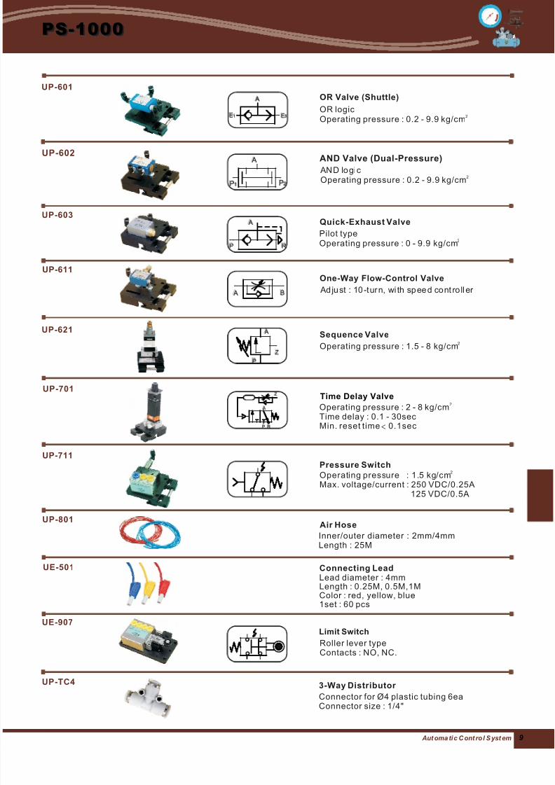
Operating pressure : 1.5 - 8 kg/cm2
Sequence Valve
Pilot typeOperating pressure : 0 - 9.9 kg/cm
2
Quick-Exhaust Valve
Ad ju st : 10 -t ur n, wi th sp ee d cont roll er
One-Way Flow-Control Valve
UP-621
UP-603
UP-611
PP RR
A A
A A BB
PP
ZZ
A A
Operating pressure : 1.5 kg/cmMax. voltage/current : 250 VDC/0.25A
125 VDC/0.5A
2
UP-711Pressure Switch
Inner/outer diameter : 2mm/4mmLength : 25M
UP-801Air Hose
Operating pressure : 2 - 8 kg/cmTime delay : 0.1 - 30secMin. reset time 0.1sec
2
<
Time Delay ValveUP-701
R
RP
A
A
Z
Z
Lead diameter : 4mmLength : 0.25M, 0.5M,1MColor : red, yellow, blue1set : 60 pcs
Connecting Lead
Roller lever typeContacts : NO, NC.
Limit Switch
UE-501
UE-907
Connector for Ø4 plastic tubing 6eaConnector size : 1/4"
3-Way Distributor UP-TC4
AN D lo gi cOperating pressure : 0.2 - 9.9 kg/cm
2
UP-602AND Valve (Dual-Pressure)
P
P1 P
P2
A A
OR logicOperating pressure : 0.2 - 9.9 kg/cm
2
UP-601
OR Valve (Shuttle)
E
E2 E1
A A
7/25/2019 Catalogo Banco Neumatico
http://slidepdf.com/reader/full/catalogo-banco-neumatico 5/910
PS-1000
Aut oma ti c C ont rol Sy ste m
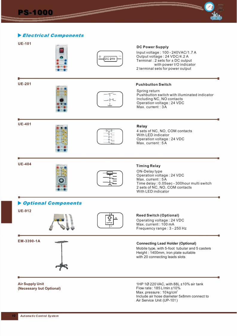
4 sets of NC, NO, COM contactsWith LED indicator Operation voltage : 24 VDCMax. current : 5 A
RelayUE-401
ON-Delay type
Operation voltage : 24 VDCMax. current : 5 ATime delay : 0.05sec - 300hour multi switch2 sets of NC, NO, COM contactsWith LED indicator
UE-404Timing Relay
Operating voltage : 24 VDCMax. current : 100 mAFrequency range : 3 - 250 Hz
Reed Switch (Optional)
UE-912
1HP 1Ø 220 VAC, with 88L ±10% air tankFlow rate : 185 L/min ±10%Max. pressure : 10 kg/cmInclude air hose diameter 5x8mm connect to Air Service Unit (UP-101)
2
Air Supply Unit
(Necessary but Optional)
Optional Components
EM-3390-1A
Mobile type, with 5-foot tubular and 5 castersHeight : 1400mm, iron plate suitablewith 20 connecting leads slots
Connecting Lead Holder (Optional)
Input voltage : 100 - 240VAC/1.7 AOutput voltage : 24 VDC/4.2 ATerminal : 2 sets for ± DC output
with power I/O indicator 2 terminal sets for power output
DC Power SupplyUE-101
Spring returnPushbutton switch with illuminated indicator Including NC, NO contactsOperation voltage : 24 VDCMax. current : 3 A
Pushbutton SwitchUE-201
Electrical Components
7/25/2019 Catalogo Banco Neumatico
http://slidepdf.com/reader/full/catalogo-banco-neumatico 6/911 Aut oma ti c C ont ro l S yst em
PS-1000
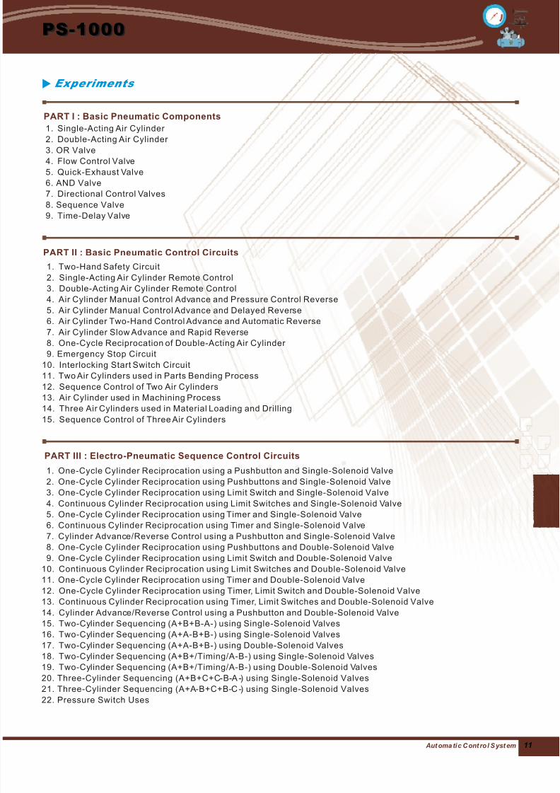
1. Single-Acting Air Cylinder
2. Double-Acting Air Cylinder 3. OR Valve
4. Flow Control Valve
5. Quick-Exhaust Valve
6. AND Valve
7. Directional Control Valves
8. Sequence Valve
9. Time-Delay Valve
1. Two-Hand Safety Circuit
2. Single-Acting Air Cylinder Remote Control3. Double-Acting Air Cylinder Remote Control
4. Air Cylinder Manual Control Advance and Pressure Control Reverse
5. Air Cylinder Manual Control Advance and Delayed Reverse
6. Air Cylinder Two-Hand Control Advance and Automatic Reverse
7. Air Cylinder Slow Advance and Rapid Reverse
8. One-Cycle Reciprocation of Double-Acting Air Cylinder
9. Emergency Stop Circuit
10. Interlocking Start Switch Circuit
11. Two Air Cylinders used in Parts Bending Process
12. Sequence Control of Two Air Cylinders
13. Air Cylinder used in Machining Process
14. Three Air Cylinders used in Material Loading and Drilling
15. Sequence Control of Three Air Cylinders
1. One-Cycle Cylinder Reciprocation using a Pushbutton and Single-Solenoid Valve
2. One-Cycle Cylinder Reciprocation using Pushbuttons and Single-Solenoid Valve
3. One-Cycle Cylinder Reciprocation using Limit Switch and Single-Solenoid Valve
4. Continuous Cylinder Reciprocation using Limit Switches and Single-Solenoid Valve
5. One-Cycle Cylinder Reciprocation using Timer and Single-Solenoid Valve
6. Continuous Cylinder Reciprocation using Timer and Single-Solenoid Valve
7. Cylinder Advance/Reverse Control using a Pushbutton and Single-Solenoid Valve
8. One-Cycle Cylinder Reciprocation using Pushbuttons and Double-Solenoid Valve
9. One-Cycle Cylinder Reciprocation using Limit Switch and Double-Solenoid Valve10. Continuous Cylinder Reciprocation using Limit Switches and Double-Solenoid Valve
11. One-Cycle Cylinder Reciprocation using Timer and Double-Solenoid Valve
12. One-Cycle Cylinder Reciprocation using Timer, Limit Switch and Double-Solenoid Valve
13. Continuous Cylinder Reciprocation using Timer, Limit Switches and Double-Solenoid Valve
14. Cylinder Advance/Reverse Control using a Pushbutton and Double-Solenoid Valve
15. Two-Cylinder Sequencing (A+B+B-A-) using Single-Solenoid Valves
16. Two-Cylinder Sequencing (A+A-B+B-) using Single-Solenoid Valves
17. Two-Cylinder Sequencing (A+A-B+B-) using Double-Solenoid Valves
18. Two-Cylinder Sequencing (A+B+/Timing/A-B-) using Single-Solenoid Valves
19. Two-Cylinder Sequencing (A+B+/Timing/A-B-) using Double-Solenoid Valves
20. Three-Cylinder Sequencing (A+B+C+C B A ) using Single-Solenoid Valves
21. Three-Cylinder Sequencing (A+A B+C+B C ) using Single-Solenoid Valves
22. Pressure Switch Uses
- - -
- - -
Experiments
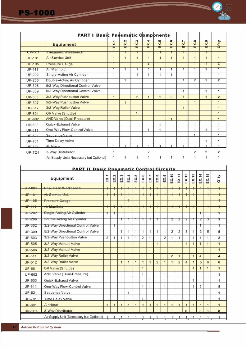
PART I : Basic Pneumatic Components
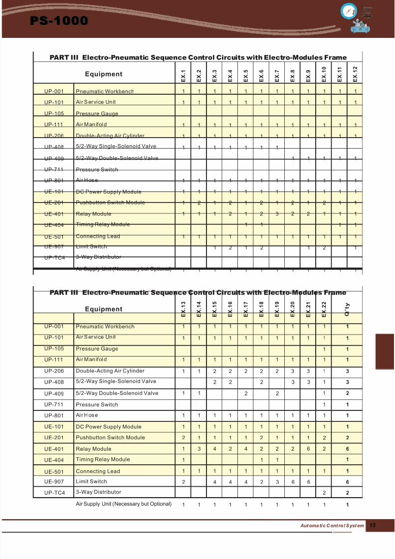
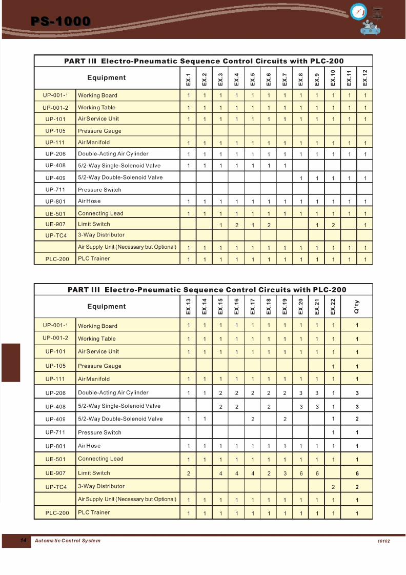
PART III : Electro-Pneumatic Sequence Control Circuits
PART II : Basic Pneumatic Control Circuits
7/25/2019 Catalogo Banco Neumatico
http://slidepdf.com/reader/full/catalogo-banco-neumatico 7/912
PS-1000
Aut oma ti c C ont rol Sy ste m
E X . 1
U P- 001 Pneumatic Wor kbenc h
Equipment
PART I Basic Pneumatic Components
E X . 2
E X . 3
E X . 4
E X . 5
E X . 6
E X . 7
E X . 8
E X . 9
Q ’ t y
Ai r S er vi ce Unit
Pressure Gauge
Ai r M an if ol d
UP-101
UP-105
UP-111
Double-Acting Air Cylinder UP-206
Air Supply Unit ( )Necessary but Optional
3-Way Distributor UP-TC4
UP-202 Single-Acting Air Cylinder
UP-308
UP-309
UP-503
UP-507
UP-601
UP-512
UP-602
UP-603
UP-611
UP-701
UP-621
UP-801
5/2-Way Directional Control Valve
OR Valve (Shuttle)
AN D Valv e ( Dual -Press ur e)
Quick-Exhaust Valve
One-Way Flow-Control Valve
Sequence Valve
Time Delay Valve
Ai r H os e
5/2-Way Directional Control Valve
3/2-Way Pushbutton Valve
5/2-Way Pushbutton Valve
3/2-Way Roller Valve
U P- 001 Pneumatic Wor kbenc h
Ai r S er vi ce Unit
Pressure Gauge
Ai r M an ifol d
UP-101
UP-105
UP-111
Double-Acting Air Cylinder UP-206
UP-202 Single-Acting Air Cylinder
UP-302
UP-309
UP-503
3/2-Way Directional Control Valve
5/2-Way Directional Control Valve
3/2-Way Pushbutton Valve
UP-505
UP-506
UP-511
3/2-Way Manual Valve
3/2-Way Manual Valve
3/2-Way Roller Valve
UP-512 3/2-Way Roller Valve
UP-601
UP-602
UP-603
UP-611
UP-621
OR Valve (Shuttle)
AND Valv e ( Dual -Press ur e)
Quick-Exhaust Valve
One-Way Flow-Control Valve
Sequence Valve
Air Supply Unit ( )Necessary but Optional
3-Way Distributor UP-TC4
UP-701
UP-801
Time Delay Valve
Ai r H os e
E X . 1
Equipment
PART II Basic Pneumatic Control Circuits
E X . 2
E X . 3
E X . 4
E X . 5
E X . 6
E X . 7
E X . 8
E X . 9
E
X . 1 0
E
X . 1 1
E
X . 1 2
E
X . 1 3
E
X . 1 4
E
X . 1 5
Q ’ t y
1 1 1 1 1 1 1 1 1 1
1 1 1 1 1 1 1 1 1 1
1 1 1 1 1 1 1 1 1 1
1 2 1 1 2
1 1 1 1 1 1
1 1 2 1 2
1 1
1 1 1
1 2 1 1 2 1 1 2
1 1 1
1 1
1 1
1 1
1 1 1
1 1 1 1 1
1 1
1 1
1 1 1 1 1 1 1 1 1 1
1 2 2 2 2
1 1 1 1 1 1 1 1 1 1
1 1 1 1 1 1 1 1 1 1 1 1 1 1 1 1
1 1 1 1 1 1 1 1 1 1 1 1 1 1 1 1
1 1 1 1 1 1 1 1 1 1 1 1 1 1 1 1
1 1
1 1 1 1
1 1 1 1 1 1 1 2 2 2 1 2 3 3
1 1 1
1 1 1 1 1 1 1 2 2 3 1 3 5 5
2 1 1 1 1 2 1 2 1 1 1 1 1 2
1 1 1 1 1 1
1 1
2 1 1 4 4
1 1 1 1 1 2 1 1 2 4 1 5 6 6
1 1 1 11
1 1 1
1 1 1 1
1 1 1 1 5 5
1 1
11 1
1 1 1 1 1 1 1 1 1 1 1 1 1 1 1 1
1 1 1 1 1 1 1 1 1 1 1 1 1 1 1 1
6 8 6 8
7/25/2019 Catalogo Banco Neumatico
http://slidepdf.com/reader/full/catalogo-banco-neumatico 8/913 Aut oma ti c C ont ro l S yst em
PS-1000
E X . 1
E X . 2
E X . 3
E X . 4
E X . 5
E X . 6
E X . 7
E X . 8
E X . 9
E X . 1 0
E X . 1 1
UP-001 Pneumatic Workbench
Ai r S er vi ce Unit
Pressure Gauge
Ai r M an ifol d
Double-Acting Air Cylinder
UP-101
UP-105
UP-111
UP-206
5/2-Way Double-Solenoid Valve
Equipment
PART III Electro-Pneumatic Sequence Control Circuits with Electro-Modules Frame
5/2-Way Single-Solenoid ValveUP-408
UP-409
UP-711
Connecting Lead
Pressure Switch
Ai r H os e
DC Power Supply Module
Pushbutton Switch Module
Relay Module
Timing Relay Module
UP-801
UE-101
UE-201
UE-401
UE-404
UE-501
Air Supply Unit ( )Necessary but Optional
Limit Switch
3-Way Distributor
UE-907
UP-TC4
Q ’ t y
E X . 1 2
1 1 1 1 1 1 1 1 1 1 1 1
E X . 1 3
E X . 1 4
E X . 1 5
E X . 1 6
E X . 1 7
E X . 1 8
E X . 1 9
E X . 2 0
E X . 2 1
E X . 2 2
UP-001
5/2-Way Double-Solenoid Valve
Equipment
PART III ith Electro-Modules FrameElectro-Pneumatic Sequence Control Circuits w
Pneumatic Workbench
Ai r S er vi ce Unit
Pressure Gauge
Ai r M an ifol d
Double-Acting Air Cylinder
5/2-Way Single-Solenoid Valve
UP-101
UP-105
UP-111
UP-206
UP-408
UP-409
UP-711
Connecting Lead
Pressure Switch
Ai r H os e
DC Power Supply Module
Pushbutton Switch Module
Relay Module
Timing Relay Module
UP-801
UE-101
UE-201
UE-401
UE-404
UE-501
Air Supply Unit ( )Necessary but Optional
Limit Switch
3-Way Distributor
UE-907
UP-TC4
1 1 1 1 1 1 1 1 1 1 1 1
1 1 1 1 1 1 1 1 1 1 1
1 1 1 1 1 1 1 1 1 1 1 1
1 1 1 1 1 1 1 1 1 1 1
1 1
1 1 1 1 1 1 1 1 1 1 1 1
1 1 1 1 1 1 1 1 1 1 1
1 1 2 2 2 2 2 3 3 1 3
1 1 1 1 1 1 1
2 2 2 3 3 1 3
1 1 2 2 1 2
1 1 1 1 1
1 1
1 1 1 1 1 1 1 1 1 1 1
1 1 1 1 1 1 1 1 1 1 1
1 1 1 1 1 1 1 1 1 1 1 1
1 1 1 1 1 1 1 1 1 1 1 1
1 2 1 2 1 2 1 2 1 2 1 1
2 1 1 1 1 2 1 1 1 2 2
1 1 1 2 1 2 3 2 2 1 1 1
1 1 1 1
3 4 2 4 2 2 2 6 2 61
1 1 1 1
1 1 1 1 1 1 1 1 1 1 1 1
2 4 4 4 2 3 6 6 6
1 2 1 2 1 2 1
2 2
1 1 1 1 1 1 1 1 1 1 1 1
1 1 1 1 1 1 1 1 1 1 1
1 1 1 1 1 1 1 1 1 1 1
7/25/2019 Catalogo Banco Neumatico
http://slidepdf.com/reader/full/catalogo-banco-neumatico 9/9
PS-1000
E X . 1
E X . 2
E X . 3
E X . 4
E X . 5
E X . 6
E X . 7
E X . 8
E X . 9
E X . 1 0
E X . 1 1
Double-Acting Air Cylinder UP-206
5/2-Way Double-Solenoid Valve
Equipment
PART III Electro-Pneumatic Sequence Control Circuits with PLC-200
UP-409
UP-711 Pressure Switch
Q ’ t y
E X . 1 2
1 1 1 1 1 1 1 1 1 1 1 1
E X . 1 3
E X . 1 4
E X . 1 5
E X . 1 6
E X . 1 7
E X . 1 8
E X . 1 9
E X . 2 0
E X . 2 1
E X . 2 2
5/2-Way Double-Solenoid Valve
Equipment
PART III ith PLC-200Electro-Pneumatic Sequence Control Circuits w
Ai r S er vi ce Unit
Pressure Gauge
Ai r M an ifol d
Double-Acting Air Cylinder
5/2-Way Single-Solenoid Valve
UP-101
UP-105
UP-111
UP-206
UP-408
UP-409
UP-711
Connecting Lead
Pressure Switch
Ai r H os eUP-801
UE-501
Air Supply Unit ( )Necessary but Optional
Limit Switch
3-Way Distributor
UE-907
UP-TC4
1 1 1 1 1 1 1 1 1 1 1 1
1 1 1 1 1 1 1 1 1 1 1
1 1 1 1 1 1 1 1 1 1 1 1
1 1 1 1 1 1 1 1 1 1 1
1 1
1 1 1 1 1 1 1 1 1 1 1 1
1 1 1 1 1 1 1 1 1 1 1
1 1 2 2 2 2 2 3 3 1 3
2 2 2 3 3 1 3
1 1 2 2 1 2
1 1 1 1 1
1 1
1 1 1 1 1 1 1 1 1 1 1
1 1 1 1 1 1 1 1 1 1 1 1
2 4 4 4 2 3 6 6 6
1 2 1 2 1 2 1
2 2
1 1 1 1 1 1 1 1 1 1 1 1
1 1 1 1 1 1 1 1 1 1 1
1 1 1 1 1 1 1 1 1 1 1
PLC Trainer PLC-200 1 1 1 1 1 1 1 1 1 1 1 1
PLC Trainer PLC-200 1 1 1 1 1 1 1 1 1 1 1
1 1 1 1 1 1 1 1 1 1 1 1
1 1 1 1 1 1 1 1 1 1 1
UP-001-1
UP-001-2
Working Board
Working Table
UP-001-1 Working Board
UP-001-2 Workin g Table
Ai r S er vi ce UnitUP-101
Pressure GaugeUP-105
Ai r M an ifol dUP-111
Connecting LeadUE-501
Limit SwitchUE-907
3-Way Distributor UP-TC4
Air Supply Unit ( )Necessary but Optional
Ai r H os eUP-801 1 1 1 1 1 1 1 1 1 1 1 1
5/2-Way Single-Solenoid ValveUP-408 1 1 1 1 1 1 1