Taladros de Banco y de Columna Bench & Floor …medios.urrea.com/catalogo/manuales/TB512A.pdf•...
16
• TB512A • TB658A • TC658A • TC734A Taladros de Banco y de Columna Bench & Floor Mounted Drill Presses ATENCIÓN: Lea, entienda y siga las instrucciones de seguridad contenidas en este manual, antes de operar esta herramienta. WARNING: Read, understand and follow the safety rules in this manual, before operating this tool. Manual de Usuario y Garantía. User’s Manual and Warranty.
Transcript of Taladros de Banco y de Columna Bench & Floor …medios.urrea.com/catalogo/manuales/TB512A.pdf•...

• TB512A • TB658A
• TC658A• TC734A
Taladros de Banco y de ColumnaBench & Floor Mounted Drill Presses
ATENCIÓN: Lea, entienda y siga las instrucciones de seguridad contenidas en este manual, antes de operar esta herramienta.WARNING: Read, understand and follow the safety rules in this manual, before operating this tool.
Manual de Usuario y Garantía.
User’s Manual and Warranty.
TB512A-TB658A manual.indd 1 02/05/13 15:27

2
INTRODUCCIÓNEstos TALADROS DE BANCO Y COLUMNA tie-nen características que harán su trabajo más rápido y fácil. Seguridad, comodidad y confia-bilidad fueron previstos como prioridad para el diseño del mismo, haciendo más fácil su ope-ración.
ADVERTENCIA: Lea atentamente el ma- nual antes de intentar usar este producto. Asegúrese de prestar atención a todas las ad-vertencias y las precauciones de seguridad a lo largo de este manual.
NORMAS GENERALES DE SEGURIDAD
ADVERTENCIA: Lea y entienda todas las instrucciones. El no seguir las instrucciones lis-tadas a continuación puede resultar en descar-gas eléctricas, fuego o lesiones personales.
GUARDE ESTAS INSTRUCCIONES PARA FUTURAS REFERENCIAS
AREA DE TRABAJO• Mantenga su área de trabajo limpia y bien iluminada. Mesas desordenadas y áreas oscuras pueden provocar accidentes. • No use la máquina en atmósferas explosivas, tales como estar en la presencia de líquidos fla-mables, gases o polvo. Los productos eléctricos generan chispas, las cuales pueden provocar incendios.• Mantenga a los observadores, niños y visi-tantes lejos de la máquina mientras la está operando. Las distracciones pueden causarle la pérdida del control.
SEGURIDAD ELÉCTRICA
• Los productos doblemente aislados están equipados con un enchufe polarizado. Este enchufe ajustará solamente de una mane-ra en una salida polarizada. Si el enchufe no se ajusta completamente en la salida, gire el enchufe. Si aún así no se ajusta contacte a un electricista calificado para instalar la salida polarizada. El doble aislamiento elimina la necesidad de un enchufe de tres picos con descarga a tierra y un sistema de provisión de potencia con descarga a tierra.
• Evite el contacto del cuerpo con las super-ficies descargadas a tierra tales como tubos, radiadores, rangos y refrigeradores. Existe un mayor riesgo de descarga eléctrica si su cuerpo “hace tierra”.• No exponga el producto a la lluvia o a condi-ciones de humedad. La entrada de agua en la máquina aumentará el riesgo de una descarga eléctrica.• No abuse del cable Nunca use el cable para llevar el producto o tirar del cable para sacarlo del tomacorriente. Mantenga el cable lejos del calor, del aceite, bordes filosos y partes móvi-les. “ESTA HERRAMIENTA CUENTA CON UN SUJETACABLE TIPO “Y“, EN CASO DE DAÑAR-SE EL CORDÓN DE ALIMENTACIÓN, ÉSTE DE-BERÁ SER REEMPLAZADO POR EL FABRICANTE, SUS CENTROS DE SERVICIO AUTORIZADOS, O PERSONAL CALIFICADO A FIN DE EVITAR RIES-GOS.”
EXTENSIONES DE CABLE• El uso de cables dañados incrementan el ries-go de descargas eléctricas, quemaduras o des-carga eléctrica.• Si es necesario un cable de extensión, debe ser usado un cable con el tamaño adecuado de los conductores. La tabla de la siguiente página, muestra el tamaño correcto para usar dependiendo en la longitud del cable y el ran-go de amperaje especificado en la etiqueta de valores nominales del producto. Si está en duda, use el rango próximo más grande. Siempre use cables de extensión listados en UL, CSA ó NOM.TAMAÑOS RECOMENDADOS DE EXTENSIONES DE CABLE:
• Cuando esté usando el producto afuera, use una extensión para exteriores marcadas con lo siguiente: “W-A” o “W”. Estas extensiones están pensadas para trabajar en exteriores y reducen el riesgo de descarga eléctrica.
TB512A-TB658A manual.indd 2 02/05/13 15:27

E S P A Ñ O L • Manual de Usuario
3
SEGURIDAD PERSONAL• Manténgase alerta, vea lo que está haciendo y use el sentido común cuando esté operando la máquina. No use este producto cuando esté cansado o bajo la influencia de drogas o alco-hol. Un momento de distracción mientras está utilizando la máquina puede tener como resul-tado una lesión seria.• Vístase correctamente. No use ropa floja ni joyas. Recoja su cabello. Mantenga su ves-timenta, cabello y guantes lejos de las partes móviles. La ropa suelta, joyería o el pelo largo pueden ser atrapados por las partes móviles.• Evite el arranque accidental. Asegúrese que el interruptor esté en la posición de apagado an-tes de enchufar el producto. Llevar la máquina con el dedo en el interruptor de encendido o enchufar productos que tengan el interruptor en la posición de encendido provoca que ocu-rran accidentes.• No se exceda. El calzado y un buen balance permite un mejor control de la herramienta en situaciones inesperadas.• Siempre use el equipo de seguridad nece-sario: protección ocular, máscara contra polvo, zapatos de seguridad antiderrapantes, casco y protección auditiva.• Antes de conectarlo a una fuente de ener-gía (receptáculo, salida, etc.) asegúrese que el voltaje de alimentación sea el mismo que el mencionado en la etiqueta o placa de valores nominales del producto. Una fuente de poten-cia mayor que la especificada para el producto puede ocasionar lesiones serias para el usuario como también puede dañar la máquina.
USO Y CUIDADO DE LA MÁQUINA• No fuerze la herramienta de poder. Use la máquina correctamente en su aplicación y ésto le ayudará a realizar mejor y de manera más segura el trabajo para el cual fue diseñado.• No use la máquina si el interruptor de encen-dido no enciende o apaga. Cualquier máquina que no pueda ser controlada con el interruptor es peligrosa y debe ser reparada.• Desconecte el enchufe de la fuente de ener-gía antes de hacer algún ajuste, cambiar acce-sorios o guardar la máquina. Estas medidas preventivas reducen el riesgo de que la máquina se encienda accidentalmente.
• Cuando la herramienta no esté en uso, guar-delo fuera del alcance de los niños, no permita que personas que no esten familiarizadas con el uso de la máquina lo opere. Las herramien-tas electricas son peligrosas en las manos de personas no entrenadas.• Mantenga su herramienta de poder. Veri-fique si hay una mala alineación o si alguna parte móvil se encuentra trabada, partes rotas o cualquier otra condición que pueda afectar la operación de la máquina. Si hay daños haga reparar la máquina antes de usarla. Muchos accidentes son causados por máquinas con un mantenimiento pobre.• Use solamente accesorios recomendados por el fabricante de su modelo. Accesorios que funcionan para una máquina pueden ser pe-ligrosos cuando son usados en otra máquina.• Almacene las máquinas eléctricas fuera del alcance de los niños y cualquier otra persona que no esté capacitada para su manejo. Las he-rramientas son peligrosas en manos de usua-rios que no están capacitados.• No altere o use mal la máquina. Esta máquina fue construida con precisión. Cualquier altera-ción o modificación no especificada es un mal uso y puede resultar en una condición peligro-sa y a su vez puede invalidar la garantía.• Es recomendable que use un dispositivo de seguridad adecuado, tal como un interruptor térmico y diferencial cuando esté usando equi-pos eléctricos.
REPARACIÓN Y SERVICIO• La reparación de la herramienta debe ser lle-vada a cabo solamente por personal calificado. La reparación o el mantenimiento realizado por una persona no calificada puede generar peligro de lesión.• Cuando esté reparando la máquina use úni-camente partes de reemplazo idénticas. Siga las instrucciones en la sección de mantenimien-to de este manual. El uso de partes no autori-zadas o la falta de seguimiento de las instruc-ciones de mantenimiento pueden ocasionar el riesgo de una descarga eléctrica o lesión.
NORMAS ESPECÍFICAS DE SEGURIDAD• Conecte esta herramienta a un suministro eléctrico propiamente conectado a tierra.
TB512A-TB658A manual.indd 3 02/05/13 15:27

4
• Solamente utilice extensiones que tengan 3 entradas (para conexiones a tierra).• Siempre utilice lentes de seguridad y una red si tiene el cabello largo.• No utilice guantes, corbatas o ropa floja.• Mientras taladre, nunca sostenga la pieza de trabajo con la mano. Sujétela firmemente a la mesa de taladrar utilizando una prensa de banco. Nunca deje sus dedos en el lugar donde puedan tocar el taladro en caso de que la pieza de trabajo se mueva inesperadamente.• No utilice la herramienta hasta que haya sido completamente montada e instalada de acuer-do a las instrucciones. • No encienda la maquina mientras la cabeza se mueva en relación a la tabla o viceversa. No encienda la maquina hasta que haya revisado que la cabeza y la mesa han sido asegurados firmemente a la columna.• No utilice este producto si alguna parte esta dañada o en mal funcionamiento.• Ajuste la mesa o el tope de profundidad para prevenir que el taladro entre en la mesa. No realice ninguna actividad de diseño, ensamble o construcción en la mesa hasta que la herra-mienta sea encendida.• Asegúrese de que la llave del broquero (cuando aplique) haya sido removida antes de encender la máquina. • Antes de encender la herramienta, asegurese de que el broquero ha sido ensamblado correc-tamente, la broca debe haber sido montada firmemente dentro del broquero y tiene que mantener la guarda de seguridad cerrada. • Durante la operación, use la velocidad reco-mendada de acuerdo al material y tipo de broca.• Apague la máquina y quite la broca, limpie la mesa antes de dejar la máquina desatendida.• Trabe el interruptor de seguridad cuando desatienda la herramienta.
CARACTERÍSTICAS
CONOZCA SU HERRAMIENTAAntes de intentar usar este producto, familiarí-cese con todas sus características de operación y requerimientos de seguridad.Su taladro de columna fue diseñado para reali-zar hoyos en madera, metal ó plástico.
1. INTERRUPTOR DE ENCENDIDO/APAGADO.2. TAPA DEL SISTEMA DE POLEAS.3. TORNILLO.4. TORNILLO DE LA VARILLA DESLIZANTE.5. VARILLA DESLIZANTE.6. MANIJA DE TRABA.7. MANIJA.8. TUERCA DE TRABA A LA MESA.9. BROQUERO.10. GUARDA DE SEGURIDAD.11. MANIJA DE LEVANTE.12. LEVANTE DEL TALADRO.13. AJUSTE DE PROFUNDIDAD.
INSTRUCCIONES DE ENSAMBLE
ENSAMBLE DE LA HERRAMIENTA (Figs. 2-6)NOTA: Instale la maquina en una superficie nivelada y solida.• Monte la columna (16) en l base (14) usando los tornillos (15).• Inserte la cremallera (19) en el eje (18).• Mantenga la cremallera contra el lado inte-rior derecho del eje y deslice la mesa (17) sobre la columna.• Deslice el anillo esférico (20) sobre la colum-na con la abertura mas amplia hacia abajo para asegurarse que el extremo superior de la cremallera dentada este bloqueada. Apriete el tornillo (21).• Coloque la manija (7) en el eje (22) y apriete el tornillo (23).
Fig.1
TB512A-TB658A manual.indd 4 02/05/13 15:27

E S P A Ñ O L • Manual de Usuario
5
• Ponga la cabeza (24) en la parte superior de la columna. Tense firmemente los tornillos hexagonales (25) para mantener la cabeza en su lugar.
• Inserte el eje del broquero (26) con la punta cónica en el eje (27). Gire el eje del broquero hasta que la punta cónica encaje. • Deslice la llave del broquero (9) en el eje del mismo.• Inserte la guarda de seguridad (10) lo mas profundo posible en el soporte (26) • Inserte el tornillo (30) en el hoyo (29) y atornille la tuerca (31) en la rosca. Tense la tuerca.• Gire los tornillos (32) en los hoyos y aprié-telos. • Atornille la perillade levante (11) en el cuerpo del tornillo de levante (12).• Retire el aceite anticorrosivo de las pates de metal descubiertas utilizando un trapo con un podo de aceite de parafina, proceda engrasan-do las partes con aceite lubricante para maqui-nas.
Si alguna parte se perdió, o no ensambla en la maquina. No encienda la herramienta hasta que la parte dañada o perdida sea montada de acuerdo a las instrucciones.Antes de la operación revise:1. Que la mesa pueda moverse suavemente2. Que el broquero pueda ser movido arriba o abajo lentamente.3. Que la máquina no vibre cuando la encien-da.
Insertando y removiendo la broca• Compruebe que en reposo la flecha (33) señale el cero en la escala de ajuste de profundidad.• Si es requerido, aflo-je el set de tornillos (34), gire el ajuste de profundidad (13) hacia la derecha hasta que la flecha señale elvalor cero y apriete el set de tornillos.• Utilice la perilla de levante (11) para mover el broquero (9) a la profundidad deseada. Para determinar la profundidad adecuada para taladrar, refiérase a la flecha en el tope de profundidad y el valor correspondiente en la escala de ajuste de profundidad. • Afloje el set de tornillos.• Gire el ajuste de profundidad a la izquierda hasta que el tope final se ha alcanzado.• Apriete el set de tornillos.
AJUSTE DE LA MESA (Fig. 9)La mesa puede ajustarse en la altura, girarse y bajar. Ajuste de altura• Afloje la manija de traba de la columna (6).• Gire la manija (7) para ajustar la mesa (17) a la altura requerida.• Tense la manija de traba de la columna.Giro de la base • Afloje la manija de traba de la columna (6).• Gire la mesa (17) a la posición requerida.• Tense la manija de traba de la columna.Bajar la mesa• Afloje la tuerca traba de la mesa (7).• Baje la mesa (17) a la posición requerida.• Tense la tuerca traba de la mesa (7).
Fig.2 Fig.3
Fig.4
Fig.5
Fig.6
Fig.7
Fig.8
TB512A-TB658A manual.indd 5 02/05/13 15:27
6
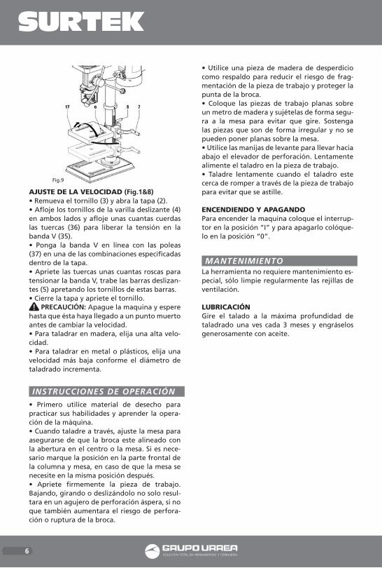
AJUSTE DE LA VELOCIDAD (Fig.1&8)• Remueva el tornillo (3) y abra la tapa (2).• Afloje los tornillos de la varilla deslizante (4) en ambos lados y afloje unas cuantas cuerdas las tuercas (36) para liberar la tensión en la banda V (35).• Ponga la banda V en línea con las poleas (37) en una de las combinaciones especificadas dentro de la tapa.• Apriete las tuercas unas cuantas roscas para tensionar la banda V, trabe las barras deslizan-tes (5) apretando los tornillos de estas barras.• Cierre la tapa y apriete el tornillo.
PRECAUCIÓN: Apague la maquina y espere hasta que ésta haya llegado a un punto muerto antes de cambiar la velocidad. • Para taladrar en madera, elija una alta velo-cidad.• Para taladrar en metal o plásticos, elija una velocidad más baja conforme el diámetro de taladrado incrementa.
INSTRUCCIONES DE OPERACIÓN
• Primero utilice material de desecho para practicar sus habilidades y aprender la opera-ción de la máquina. • Cuando taladre a través, ajuste la mesa para asegurarse de que la broca este alineado con la abertura en el centro o la mesa. Si es nece-sario marque la posición en la parte frontal de la columna y mesa, en caso de que la mesa se necesite en la misma posición después. • Apriete firmemente la pieza de trabajo. Bajando, girando o deslizándolo no solo resul-tara en un agujero de perforación áspera, si no que también aumentara el riesgo de perfora-ción o ruptura de la broca.
• Utilice una pieza de madera de desperdicio como respaldo para reducir el riesgo de frag-mentación de la pieza de trabajo y proteger la punta de la broca.• Coloque las piezas de trabajo planas sobre un metro de madera y sujételas de forma segu-ra a la mesa para evitar que gire. Sostenga las piezas que son de forma irregular y no se pueden poner planas sobre la mesa.• Utilice las manijas de levante para llevar hacia abajo el elevador de perforación. Lentamente alimente el taladro en la pieza de trabajo.• Taladre lentamente cuando el taladro este cerca de romper a través de la pieza de trabajo para evitar que se astille.
ENCENDIENDO Y APAGANDOPara encender la maquina coloque el interrup-tor en la posición “I” y para apagarlo colóque-lo en la posición “0”.
MANTENIMIENTOLa herramienta no requiere mantenimiento es-pecial, sólo limpie regularmente las rejillas de ventilación.
LUBRICACIÓNGire el talado a la máxima profundidad de taladrado una ves cada 3 meses y engráselos generosamente con aceite.
Fig.9
TB512A-TB658A manual.indd 6 02/05/13 15:27

ESPECIFICACIONES TÉCNICAS
VOLTAJE-FRECUENCIADIÁMETRO DE GIROPOTENCIA DEL MOTORVELOCIDAD DE EJENO. DE VELOCIDADESTAMAÑO DE LA MESA TAMAÑO DE LA BASE CARRERA DE HUSILLOCAPACIDAD DE BROQUERO PESO
120 V ~ 60 Hz8,1" (208 mm)300 W(760 - 3 070) r/min5160 mm x 160 mm291 mm x 183 mm2" (50 mm)1/2" (13 mm) 16,5 kg (36,5 lb)
VOLTAJE-FRECUENCIADIÁMETRO DE GIROPOTENCIA DEL MOTORVELOCIDAD DE EJENO. DE VELOCIDADESTAMAÑO DE LA MESA TAMAÑO DE LA BASE CARRERA DE HUSILLOCAPACIDAD DE BROQUERO PESO
120 V ~ 60 Hz13" (330 mm)550 W(210 - 3 840) r/min16270 mm x 270 mm273 mm x 456 mm3,1" (80 mm)5/8" (16 mm) 60 kg (132 lb)
VOLTAJE-FRECUENCIADIÁMETRO DE GIROPOTENCIA DEL MOTORVELOCIDAD DE EJENO. DE VELOCIDADESTAMAÑO DE LA MESA TAMAÑO DE LA BASE CARRERA DE HUSILLOCAPACIDAD DE BROQUERO PESO
120 V ~ 60 Hz10" (252 mm)550 W(220 - 2 450) r/min12200 mm x 195 mm355 mm x 235 mm2,3" (60 mm)5/8" (16 mm) 38 kg (83,7 lb)
VOLTAJE-FRECUENCIADIÁMETRO DE GIROPOTENCIA DEL MOTORVELOCIDAD DE EJENO. DE VELOCIDADESTAMAÑO DE LA MESA TAMAÑO DE LA BASE CARRERA DE HUSILLOCAPACIDAD DE BROQUERO PESO
120 V ~ 60 Hz15" (380 mm)750 W(250 - 3 000) r/min12300 mm x 300 mm300 mm x 500 mm3 5/32" (80 mm)3/4" (19 mm) 82 kg (180,7 lb)
TB512A TC658A
TB658A TC734A
E S P A Ñ O L • Manual de Usuario
7
TB512A-TB658A manual.indd 7 02/05/13 15:27

8
INTRODUCTIONYour BENCH & FLOOR MOUNTEDDRILL PRESS has many features that will make your job fast-er and easier. Safety, performance and reliabil-ity have been given top priority in the design of this tool, qualities to make easy to maintain and to operate.
WARNING: Carefully read the entire man-ual before attempting to use this tool. Make sure to pay special attention to the safety rules and indications, plus all the warnings and cau-tions of this manual.
GENERAL SAFETY RULES
WARNING: Read and understand all in-structions. Failure to follow all indications list-ed below, may result in electric shock, fire and/or serious personal injury.
SAVE THESE INSTRUCTIONS.
WORK AREA• Keep your work area clean and well lit. Clut-tered benches and dark areas may cause acci-dents.• Do not operate power tools in explosive at-mospheres, such as in the presence of flam-mable liquids, gases or dust. Some power tools create sparks which may provoke fire.• Keep away observers, children and visitors while operating a power tool. Distractions can cause you to lose control.
ELECTRIC SAFETY
• Double insulation eliminates the need for the three wire grounded power cord and ground-ed power supply system.• Avoid the body contact with grounded sur-faces such as pipes, radiators and refrigerators. There is an increased risk of electric shock if your body is grounded.• Don’t expose power tools to rain or wet con-ditions. The precense of water into power tools will increase the risk of electric shock.• Do not abuse of the power cord. Never use the power cord to carry the tool and do not pull the plug off the outlet. Keep the cable away of heat, oil, sharp edges or moving parts.
Replace damaged cords immediately. Dam-aged cords increase the risk of electric shock.• When operating a power tool outside, use an outdoor extension cord marked “W-A” or “W”. These cords are rated for outdoor use and reduce the risk of electric shock.
EXTENSION CORDSReplace damaged cords immediately. The use of damaged cords can shock, burn or electric shock. If an extension cord is necessary, a cord with adequate size conductors should be used to prevent excessive voltage drop, loss of pow-er or overheating. The table below shows the correct size to use, depending on cord length and nameplate amperage rating of tools. In case of doubt use the next heavier gauge. Al-ways use UL listed extension cords.
SIZE RECOMMEND EXTENSION CABLES
PERSONAL SAFETY
• Stay alert, watch what you are doing and use common sense when operating a power tool.Don’t use the tool if you are tired or under the influence of drugs, alcohol or medication. A moment of unattention while operating pow-er tools may cause a serious personal injury.• Dress properly. Do not wear loose clothing or jewellery. Contain long hair. Keep your hair, clothing and gloves away of moving parts. Loose clothes, jewellery or long hair can be caught in moving parts.• Avoid an accidental starting. Be sure that the switch is OFF before plugging in. Carrying tools with the finger on the switch or plug in the tool switch in ON may cause accidents.• Remove the adjusting keys or wrenches be-fore turning the tool on. A wrench or a key that is left close to a rotating part of the tool may provoke a personal injury.• Do not overreach. Keep proper footing and balance at all times. Proper footing and bal-ance enables better control of the tools on un-expected situations.
TB512A-TB658A manual.indd 8 02/05/13 15:27

9
• Use safety equipment. Always wear eye pro-tection. Dust mask, nonskid safety shoes, hard hat, or hearing protection must be used for ap-propriate conditions.• Before connecting the tool to a power source (receptacle, outlet, etc.) be sure that the volt-age supplied is the same as that one specified on the nameplate of the tool. To use a not specified voltage may cause a serious injury to the user as well as damage the tool.
TOOL USE AND CARE
• Do not force the power tool. Use the correct tool for the application. The correct tool will do the job better and more safely at the rate that it was designed to work at.• Use clamps or other practical way to secure and support the workpiece to a estable plat-form. Holding the work by hand or against your body is unestable and may cause loss of control.• Do not use tools if switch does not turn it on or off. Any tool that cannot be controlled whith the switch is dangerous and must be re-paired.• Disconnect the plug from the power source before making any adjustments, changing ac-cessories or storing the tool. This preventive safety measures reduce the risk of accidental starting of the tool.• When the power tool is not in use, store it out of the reach of children, and do not al-low individuals who are not familiar with the power tool or these instructions to operate it. Power tools are dangerous in the hands on un-trained users.• Maintain the power tool. Check for misalign-ment or binding of moving parts, broken parts, and any other condition that may affect the operation of the power tool. If it is damaged, have it repaired before using. Many accidents are caused by poorly maintained power tools.• Check for misalignment or bonding of mov-ing parts, breakage parts, and any other condi-tion that may affect the tools operation. If you find a damaged tool, take it to service before use it. • Use only accessories that are recommended by the manufacturer of your model. Suitable accessories for one tool, may become hazard-ous when are used on another tool.
• Do not alter or misuse the tool. These tools have been built by precision. Any alteration or modification not specified is misuse and may result in a dangerous condition.• Is recommendable to use a safety device suit-able, such a thermal and diferential switch when you are using an electric equipment.
REPAIR AND SERVICE• Tool service must be perfomed only by quali-fied repair personnel. Service or maintenance performed by unqualified personnel could re-sult in a risk of injury.• When tool service is required, use only identi-cal replacement parts and follow the instruc-tions from Maintenance Section in this manual. The use of unauthorized parts or failure to fol-low Maintenance Instructions may cause a risk of electric shock or injury.
SPECIFIC SAFETY RULES
• Only connect the machine to an earthed mains supply. Only use tree-core extension cords.• Always wear safety goggles and a hairnet for long hair.• Do not wear gloves, ties or loose clothing.• While drilling, never hold the workpiece by hand, but firmly tighten it to the drilling table using a vice e.g. Never keep your fingers on a place where they could touch the drill in case the workpiece should move unexpectedly.• Do not use the machine until it has been mounted and installed completely according to the instructions.• Do not switch on the machine while mov-ing the head relative to the table or viceversa. Do not switch on the machine until having checked that head and table have been tight-ened firmly to the pillar.• Do not use the machine if any part is dam-aged or badly functioning.• Adjust the table or depth stop to prevent the drill from entering the table. Do not perform any design, assembly or construction activities on the table while the machine is switched on.• Make sure that the chuck key (if applicable) has been removed before switching on the ma-chine.
E N G L I S H • User's manual
TB512A-TB658A manual.indd 9 02/05/13 15:27

10
• Before switching on the machine, make sure the chuck has been mounted correctly, the drill has been mounted into the chuck firmly and the safety guard has been shut.• In operation, use the recommended speed for the drilling accessories and the material.• Switch off the power, remove the drill and clean the table before leaving the machine.• Lock the on/off switch when leaving the ma-chine.
FEATURESKNOW YOUR TOOLBefore attempting to use this product, become familiar with all of its operating features and safety requirements.
Your drill press has been designad for drilling hales in wood, metal and plastics.
1. ON/OFF SWITCH.2. PULLEY SYSTEM COVER.3. SCREW.4. SLIDE ROD SCREW.5. SLIDE ROD.6. PILLAR LOCKING HANDLE.7. HANDLE.8. TABLE LOCKING NUT.9. CHUCK.10. SAFETY GUARD.11. LIFT HANDLE.12. DRILL LIFT13. DEPTH ADJUSTMENT.
ASSEMBLY INSTRUCTIONS
ASSEMBLING THE MACHINE (Figs.2-6)Install the machine on a level and salid surface.• Mount the pillar (16) to the foot (14) using the bolts (15).• lnsert the toothed rack (19) into the shaft (18).• Hold the rack with the teeth against the right innerside of the shaft and slide the table (17) over the pillar.• Slide the spherical ring (20) over the pillar with the wider opening facing downward to make sure that the top end of the toothed rack is locked. Tighten the Allen screw (21).• Place the handle (7) onto the spindle (22) and tighten the screw (23).
• Place the head (24) on top of the pillar. Firmly tighten the Allen screws (25) to keep the head in place.
• lnsert the drill shaft (26) witll the conical end into the shaft (27). Turn the drill shaft until the conical end engages.
Fig.2 Fig.3
Fig.4
Fig.5
Fig.6
Fig.1
TB512A-TB658A manual.indd 10 02/05/13 15:27

E N G L I S H • User's manual
11
• Slide the chuck key (9) onto the drill shaft.• lnsert the safety guard (10) as far into the bracket (26) as possible.• lnsert the screw (30) into the hole (29) and screw a nut (31) onto the thread. Tighten the nut.• Turn the screws (32) into the hales. Tighten the screws. • Screw the lift han-dles (11) into the body of the drilllift (12).• Remove the anti-corrosiva oil on the uncov-ered metal parts using a cloth and a little par-rafin oil. Proceed with greasing the parts with machine lubricating oil.lf parts are missing, do not assemble the ma-chine, do not plug in and do not switch on the machine until the missing parts have been mounted according to the instructions.Check befare operation:1. That the table can be moved smoothly;2. That the drilllift can be moved up and downsmoothly;3. That the machine does not shake when lt isswitched on.
ADJUSTING THE DRILLING DEPTH• Check whether in rest position the arrow (33) points to the zero value on the depth ad-justment scale.• lf required, slacken the set screw (34), turn the depth adjust-ment (13) clockwise until the arrow points to the zero value, and tighten the set screw.• Use the lift handles (11) to move the chuck (9) to the required drilllng depth. Todetermine the required drilling depth, refer to the arrow on the depth stop and the corresponding value on the depth adjustment scale.• Slacken the set screw.• Turn the depth adjustment counter-clockwise until the end stop has been reached.• Tighten the set screw.
ADJUSTING THE TABLE (Fig.8)The table can be height-adjusted, turned and toppled.Height adjustment:• Slacken the pillar locking handle (6).• Tum the handle (7) to adjust the table (17) to the required height.• Tighten the pillar locking handle.Turning:• Slacken the pillar locking handle (6).• Turn the table (17) to the requíred position.• Tighten the pillar locking handle.Toppling:• Slacken the table locking nut (7).• Topple the table (17) to the required position.• Tighten the table locking nut (7).
ADJUSTING THE SPEED (Fig.1&8)• Remove the screw (3) and open the cover (2).• Slacken the slide rod screws (4) on both sides and slacken the nuts (36) a few threads to re-lease the tension on the rear V-belt (35).• Put the V-belts in line on the pulleys (37) in one of the combinations specified on the in-side of the cover.• Tighten the nuts a few threads to tension the rear V-belt. Clamp the slide rods (5) by tighen-ing the slide rod screws.• Glose the cover and tighten the screw.
WARNING: Switch off the machine and wait until the machine has cometo a complete standstill before changing the speed. Adjust the speed to the material to be drilled and the drilling diameter.• For drilling in wood, choose a high speed.• For drilling in metal and plastics, choose a lower speed as the drilling diameter increases.
Fig.7
Fig.8
Fig.9
TB512A-TB658A manual.indd 11 02/05/13 15:27

12
OPERATION INSTRUCTIONS• Use waste material to practise your skills and to learn operating the machine first.• When drilling through, adjust the table to make sure that the drill is alligned with the opening in the centre of the table. lf required, mark the position on the front side of pillar and table in case the table should be set in the same position at a later time.• Securely tighten the workpiece. Toppling, turning or sliding not only results in a rough drilling hole, it al so in creases the risk of the drill breaking off.• Use a piece of waste wood as a backup to re-duce the risk of the workpiece splintering and to protect the drill tip.• Place flat workpieces on a wooden under-ground and clamp securely to the table to pre-vent them from turning. Support workpieces that are irregular of shape and cannot be put flat onto the table.• Use the lift handles to bring the drill lift downwards. Slowly feed the dril i'nto thework-piece.• Drill slowly when the drill is about to break through the workpiece to prevent splintering.
SWITCHING ON AND OFFTo switch the machine on, set the on/off switch to '1'. To switch the machine off, set the on/off switch to '0'.
MAINTENANCE
The machine does not require any special maintenance.• Regularly clean the ventilation slots.
LUBRICATION• Turn the drill shift to the maximum drilling depth once per 3 months and grease it slightly with oil.
TECHNICAL DATA
VOLTAGE-FREQUENCYSWINGMOTOR POWERSPINDLE SPEEDNUMBER OF SPEEDSTABLE SIZEBASE SIZECHUCK STROKECHUCK CAPACITYWEIGHT
120 V ~ 60 Hz8,1" (208 mm)300 W(760 - 3 070) r/min5160 mm x 160 mm291 mm x 183 mm2" (50 mm)1/2" (13 mm) 16,5 kg (36,5 lb)
VOLTAGE-FREQUENCYSWINGMOTOR POWERSPINDLE SPEEDNUMBER OF SPEEDSTABLE SIZEBASE SIZECHUCK STROKECHUCK CAPACITYWEIGHT
120 V ~ 60 Hz10" (252 mm)550 W(220 - 2 450) r/min12200 mm x 195 mm355 mm x 235 mm2,3" (60 mm)5/8" (16 mm) 38 kg (83,7 lb)
TB512A
TB658A
VOLTAGE-FREQUENCYSWINGMOTOR POWERSPINDLE SPEEDNUMBER OF SPEEDSTABLE SIZEBASE SIZECHUCK STROKECHUCK CAPACITYWEIGHT
120 V ~ 60 Hz13" (330 mm)550 W(210 - 3 840) r/min16270 mm x 270 mm273 mm x 456 mm3,1" (80 mm)5/8" (16 mm) 60 kg (132 lb)
VOLTAGE-FREQUENCYSWINGMOTOR POWERSPINDLE SPEEDNUMBER OF SPEEDSTABLE SIZEBASE SIZECHUCK STROKECHUCK CAPACITYWEIGHT
120 V ~ 60 Hz15" (380 mm)750 W(250 - 3 000) r/min12300 mm x 300 mm300 mm x 500 mm3 5/32" (80 mm)3/4" (19 mm) 82 kg (180,7 lb)
TC658A
TC734A
TB512A-TB658A manual.indd 12 02/05/13 15:27

13
DIAGRAMAS DE VELOCIDAD / SPEED CHARTS
ARBOL
EJE /SPINDLE
A-4
1-A
A-2
3-C
B-1
5-E
C-1
A-3
2-B
B-3
4-D
C-2 D-2
B-4 C-4 D-3 D-1
220
760
450
1 630
800
3 070
1 500
300
1 150
530
2 180
1 300 2 200
350 580 1 400 2 450
1
1 A
A
2
2 B
B
3
3 C
C
4
4 D
D
5 E
Diagráma para el TB512A / TB512A Speed Chart
Diagráma para el TB658A / TB658A Speed Chart
MOTOR
MOTOR
ADVERTENCIAS:• Mantenga sus manos alejadas del recorrido del husillo. • Nunca realice mantenimiento con el motor funcionando. • Asegure la maquina firmemente para evitar movimientos inesperados.
WARNINGS:• Keep hands away of the chuck stroke. • Service bench drill only when it’s not in operation. • Steady the machine to avoid personal inju-ries.
Manua l de usuar io / User ’s manua l
TB512A-TB658A manual.indd 13 02/05/13 15:27

14
EJE /SPINDLE
ARBOL
A-4
A-5
A-2
B-4
B-1
B-1
B-1
D-3
A-3
A-4
B-3
C-5
C-2
C-3
D-2
C-1
B-4
B-5
A-3
C-4
B-2
A-1
D-3
D-4
C-2
D-3
D-2
D-1
250
210
570
475
1 180
1 190
1 900
1 930
400
305
650
530
1 350
1 195
2 200
2 420
450
315
450
700
860
900
1 500
1 350
1 710
3 000
2 700
3 840
1
1
A
A
2
2
B
B
3
3
C
C
4
45
D
D
Diagráma para el TC658A / TC658A Speed Chart
Diagráma para el TC734A / TC734A Speed Chart
MOTOR
MOTOR
TB512A-TB658A manual.indd 14 02/05/13 15:27

15
Manual de usuar io / User ’s manua l
Notas / Notes
TB512A-TB658A manual.indd 15 02/05/13 15:27

16
E S P A Ñ O LPOLIZA DE GARANTÍA
E N G L I S HWARRANT POLICY
Urrea Herramientas Profesionales S.A. de C.V. Warranties this product for a period of 1 year in its parts, components and manual labour against any manufacture defect from the purchasing date.
Purchase date: ____/____/____Product:____________________Brand:______________________Model:______________________
______________________________Distributor seal and signature
Sold and Imported by:Urrea Herramientas Profesionales S.A. de C.V. km 11,5 Carretera A El Castillo, El Salto, Jalis-co, México. C. P. 45680, Tel. (33) 3208 7900, RFC UHP900402Q29
Terms:In order to make warranty effective you must pres-ent the product along with the warranty properly fillled and signed to an authorized distributor or service center.
Urrea Herramientas Profesionales S.A. de C.V. will cover the transportation cost related to the warranty.
This warranty is not applicable in the follow-ing cases:· When the product has not been used according to normal conditions or natural wear of its parts. · When the product has not been used according with this user’s manual instructions. · When the product has been fixed or modified by unauthorized or unqualified person.
Urrea Herramientas Profesionales S.A. de C.V. garantiza este producto por el termino de 1 año en sus piezas, componentes y mano de obra con-tra cualquier defecto de fabricación a partir de la fecha de entrega.
Fecha de venta: ____/____/____Producto: ___________________Marca: ______________________Modelo: ____________________
______________________________Sello y firma de distribuidor
Comercializado e Importado por:Urrea Herramientas Profesionales S.A. de C.V. km 11,5 Carretera A El Castillo, El Salto, Ja-lisco, México. C. P. 45680, Tel. (33) 3208 7900, RFC UHP900402Q29
Condiciones:Para hacer efectiva la garantía deberá presentar el producto junto con la poliza de garantia debi-damente firmada y sellada por el establecimiento donde la adquirio, en cualquiera de los centros de servicio autorizados. Los gastos de transportación que se deriven del cumplimiento de la garantía seran cubiertos por:Urrea Herramientas Profesionales S.A. de C.V.
Esta garantía no será valida en los siguientes casos:· Cuando el producto haya sido utilizado en condi-ciones distintas a las normales o al desgaste natu-ral de sus partes. · Cuando el producto no haya sido operado de acuerdo al instructivo de uso que lo acompaña. · Cuando el producto haya sido alterado o repara-do por personas no autorizadas.
TB512A-TB658A manual.indd 16 02/05/13 15:27