
Cadcamnet Solidedge v19review Tcm1023-22637
5
eprinted from ADCAMNet June 22, 2006 ©2006 yon Research orporation Solid Edge V19ʼs new gear relationships provide complete set of gear types, including rotation to rotation, linear to rotation, and linear to linear. This xample shows a r ack and pinion steering echanism. New Enhancements in Solid Edge By David Cohn June 22, 2006 – Last week, we reported on our recent meeting with UGS representatives, uring which we were briefed on the latest release of Femap and the announcement of the NX CAM Express, the newest component in the companyʼs V elocity Series (see “Enha ncing ts V elocity Series”). This week, we turn our attention to the upcoming release of So lid Edge 19. The new version of Solid Edge, which will begin shipping in July, includes hundreds of enhanced capabilities for creating, sharing, and managing design information as well as new tools for motion simulation, assembly and disassembly videos, 3D design annotation, and visual collaboration. There are lso a host of new sheet metal capabilities. u mo on smua on ne of the biggest new areas in V19 is motion simulation. Using new tools in Solid Edge, engineers can quickly create accurate, realistic conceptual motion studies during the design phase, animating designs to demonstrate product unctionality in real-time. Solid Edge V19 dds new capabilities to define motion relationships and drivers, such as gears, pulleys, hydraulic cylinders, and motors. ears are an enhanced form of assembly relationship. They work by determining relationship (or ratio) between adjacent parts, such as gears and pulleys, or rotation to rotation, or even the linear relationships that youʼd have in an ctuator. Y ou can then add motors to rive these designs through their range f motion, with complete control over irection, speed, and travel. SPECIAL REPRINT featuring www.cadcamnet.com
-
Upload
thejasvgmailcom -
Category
Documents
-
view
231 -
download
0
Transcript of Cadcamnet Solidedge v19review Tcm1023-22637
8/8/2019 Cadcamnet Solidedge v19review Tcm1023-22637
http://slidepdf.com/reader/full/cadcamnet-solidedge-v19review-tcm1023-22637 1/4
eprinted from
ADCAMNet
June 22, 2006©2006
yon Research
orporation
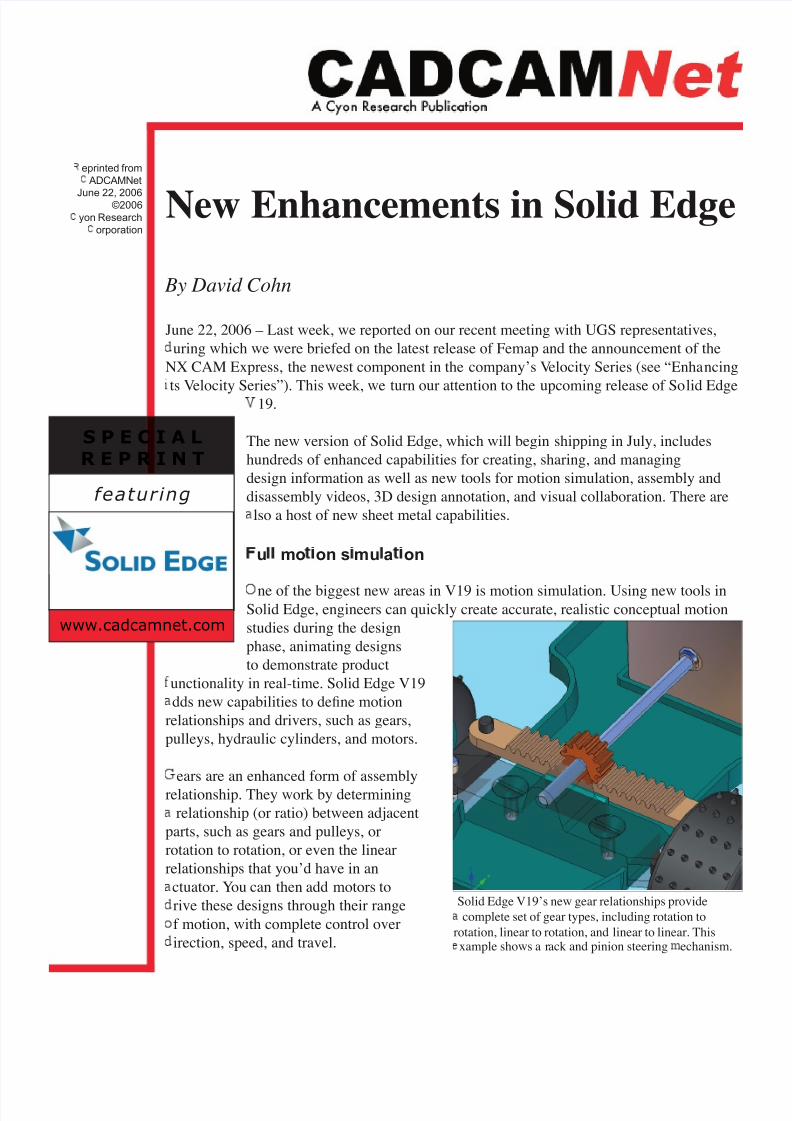
Solid Edge V19ʼs new gear relationships provide
complete set of gear types, including rotation to
rotation, linear to rotation, and linear to linear. Thisxample shows a rack and pinion steering echanism.
New Enhancements in Solid Edge
By David Cohn
June 22, 2006 – Last week, we reported on our recent meeting with UGS representatives,
uring which we were briefed on the latest release of Femap and the announcement of the
NX CAM Express, the newest component in the companyʼs Velocity Series (see “Enhancing
ts Velocity Series”). This week, we turn our attention to the upcoming release of Solid Edge
19.
The new version of Solid Edge, which will begin shipping in July, includes
hundreds of enhanced capabilities for creating, sharing, and managing
design information as well as new tools for motion simulation, assembly and
disassembly videos, 3D design annotation, and visual collaboration. There are
lso a host of new sheet metal capabilities.
u mo on s mu a on
ne of the biggest new areas in V19 is motion simulation. Using new tools inSolid Edge, engineers can quickly create accurate, realistic conceptual motion
studies during the design
phase, animating designs
to demonstrate product
unctionality in real-time. Solid Edge V19
dds new capabilities to define motion
relationships and drivers, such as gears,
pulleys, hydraulic cylinders, and motors.
ears are an enhanced form of assembly
relationship. They work by determining
relationship (or ratio) between adjacent
parts, such as gears and pulleys, or
rotation to rotation, or even the linear
relationships that youʼd have in an
ctuator. You can then add motors to
rive these designs through their range
f motion, with complete control over
irection, speed, and travel.
S P E C I A L
R E P R I N T
featuring
www.cadcamnet.com
8/8/2019 Cadcamnet Solidedge v19review Tcm1023-22637
http://slidepdf.com/reader/full/cadcamnet-solidedge-v19review-tcm1023-22637 2/4
S lid Edge V19 also includes new animation capabilities to capture, modify, and animate how parts move
as well as how theyʼre assembled. The new release introduces a new animation environment that provides
a timeline in which users can control all aspects of an animation. In addition to driving parts, users can fadeindividual parts in and out, chang the color of parts uring individual frames, and move the camera along a
path.
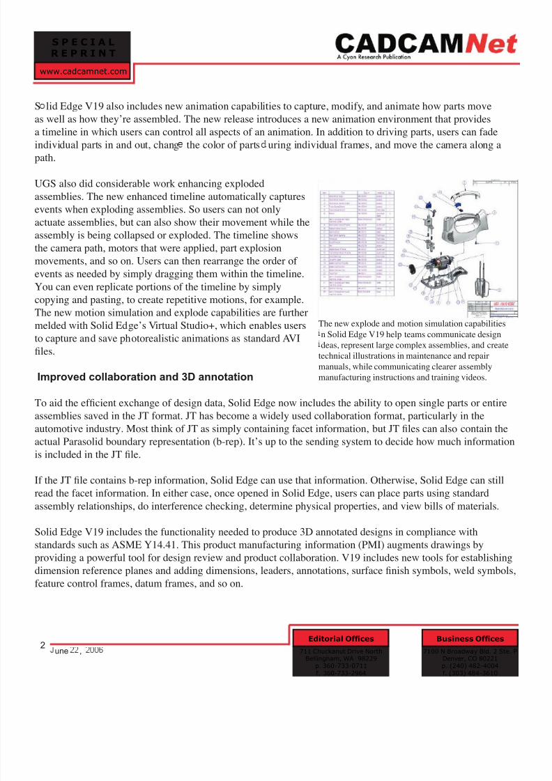
UGS also did considerable work enhancing exploded
assemblies. The new enhanced timeline automatically captures
events when exploding assemblies. So users can not only
actuate assemblies, but can also show their movement while the
assembly is being collapsed or exploded. The timeline shows
the camera path, motors that were applied, part explosion
movements, and so on. Users can then rearrange the order of
events as needed by simply dragging them within the timeline.You can even replicate portions of the timeline by simply
copying and pasting, to create repetitive motions, for example.
The new motion simulation and explode capabilities are further
melded with Solid Edgeʼs Virtual Studio+, which enables users
to capture and save photorealistic animations as standard AVI
files.
Improved collaboration and 3D annotation
To aid the efficient exchange of design data, Solid Edge now includes the ability to open single parts or entire
assemblies saved in the JT format. JT has become a widely used collaboration format, particularly in the
automotive industry. Most think of JT as simply containing facet information, but JT files can also contain the
actual Parasolid boundary representation (b-rep). Itʼs up to the sending system to decide how much information
is included in the JT file.
If the JT file contains b-rep information, Solid Edge can use that information. Otherwise, Solid Edge can still
read the facet information. In either case, once opened in Solid Edge, users can place parts using standard
assembly relationships, do interference checking, determine physical properties, and view bills of materials.
Solid Edge V19 includes the functionality needed to produce 3D annotated designs in compliance with
standards such as ASME Y14.41. This product manufacturing information (PMI) augments drawings byproviding a powerful tool for design review and product collaboration. V19 includes new tools for establishing
dimension reference planes and adding dimensions, leaders, annotations, surface finish symbols, weld symbols,
feature control frames, datum frames, and so on.
S P E C I A L
R E P R I N T
www.cadcamnet.com
7100 N Broadway Bld. 2 Ste. PDenver, CO 80221p. (240) 482-4004f. (303) 484-3610
Business Offices
711 Chuckanut Drive NorthBellingham, WA 98229
p. 360-733-0711f. 360-733-2964
Editorial Offices2
une ,
The new explode and motion simulation capabilities
n Solid Edge V19 help teams communicate design
deas, represent large complex assemblies, and create
technical illustrations in maintenance and repair
manuals, while communicating clearer assembly
manufacturing instructions and training videos.
8/8/2019 Cadcamnet Solidedge v19review Tcm1023-22637
http://slidepdf.com/reader/full/cadcamnet-solidedge-v19review-tcm1023-22637 3/4
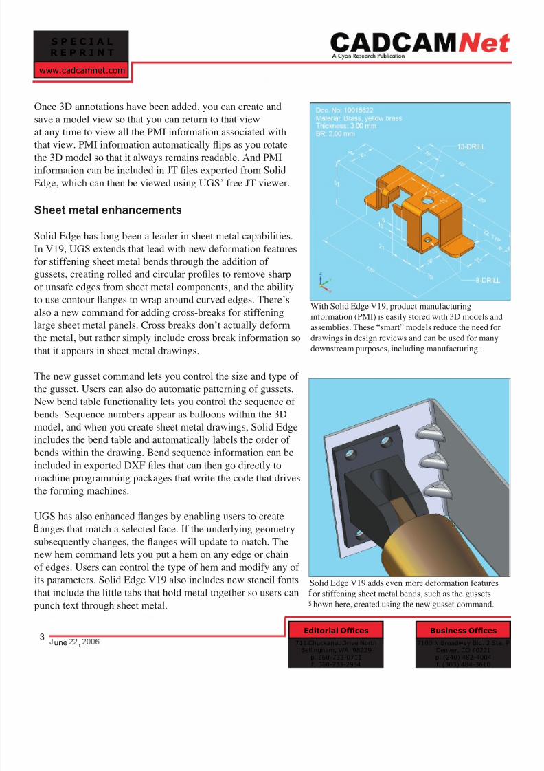
Once 3D annotations have been added, you can create and
save a model view so that you can return to that view
at any time to view all the PMI information associated withthat view. PMI information automatically flips as you rotate
the 3D model so that it always remains readable. And PMI
information can be included in JT files exported from Solid
Edge, which can then be viewed using UGSʼ free JT viewer.
Sheet metal enhancements
Solid Edge has long been a leader in sheet metal capabilities.
In V19, UGS extends that lead with new deformation features
for stiffening sheet metal bends through the addition of
gussets, creating rolled and circular profiles to remove sharp
or unsafe edges from sheet metal components, and the ability
to use contour flanges to wrap around curved edges. Thereʼs
also a new command for adding cross-breaks for stiffening
large sheet metal panels. Cross breaks donʼt actually deform
the metal, but rather simply include cross break information so
that it appears in sheet metal drawings.
The new gusset command lets you control the size and type of
the gusset. Users can also do automatic patterning of gussets.
New bend table functionality lets you control the sequence of bends. Sequence numbers appear as balloons within the 3D
model, and when you create sheet metal drawings, Solid Edge
includes the bend table and automatically labels the order of
bends within the drawing. Bend sequence information can be
included in exported DXF files that can then go directly to
machine programming packages that write the code that drives
the forming machines.
UGS has also enhanced flanges by enabling users to create
anges that match a selected face. If the underlying geometry
subsequently changes, the flanges will update to match. Thenew hem command lets you put a hem on any edge or chain
of edges. Users can control the type of hem and modify any of
its parameters. Solid Edge V19 also includes new stencil fonts
that include the little tabs that hold metal together so users can
punch text through sheet metal.
S P E C I A L
R E P R I N T
www.cadcamnet.com
7100 N Broadway Bld. 2 Ste. PDenver, CO 80221p. (240) 482-4004f. (303) 484-3610
Business Offices
711 Chuckanut Drive NorthBellingham, WA 98229
p. 360-733-0711f. 360-733-2964
Editorial Offices3
une ,
With Solid Edge V19, product manufacturing
information (PMI) is easily stored with 3D models and
assemblies. These “smart” models reduce the need for
drawings in design reviews and can be used for many
downstream purposes, including manufacturing.
Solid Edge V19 adds even more deformation features
or stiffening sheet metal bends, such as the gussets
hown here, created using the new gusset command.
8/8/2019 Cadcamnet Solidedge v19review Tcm1023-22637
http://slidepdf.com/reader/full/cadcamnet-solidedge-v19review-tcm1023-22637 4/4
Live preview shows what the sheet metal part will look like before you complete its creation, and gives you live
feedback so you can immediately see if the part can be created or not. Solid Edge also automatically determines
the cut size for the part and warns if the part is larger than the specified sheet size.
Other enhancement
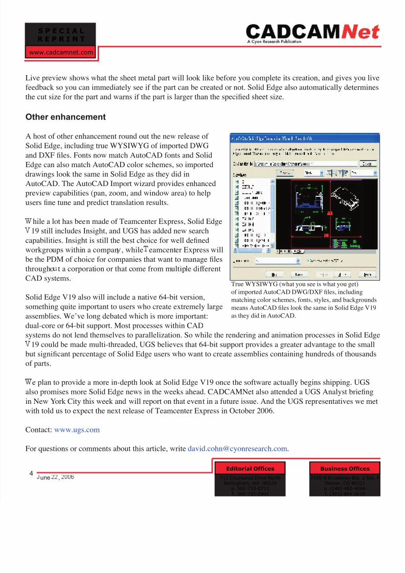
A host of other enhancement round out the new release of
Solid Edge, including true WYSIWYG of imported DWG
and DXF files. Fonts now match AutoCAD fonts and Solid
Edge can also match AutoCAD color schemes, so imported
drawings look the same in Solid Edge as they did in
AutoCAD. The AutoCAD Import wizard provides enhanced
preview capabilities (pan, zoom, and window area) to help
users fine tune and predict translation results.
hile a lot has been made of Teamcenter Express, Solid Edge
19 still includes Insight, and UGS has added new search
capabilities. Insight is still the best choice for well defined
workgroups within a compan , while eamcenter Express will
be the PDM of choice for companies that want to manage files
througho t a corporation or that come from multiple different
CAD systems.
Solid Edge V19 also will include a native 64-bit version,something quite important to users who create extremely large
assemblies. Weʼve long debated which is more important:
dual-core or 64-bit support. Most processes within CAD
systems do not lend themselves to parallelization. So while the rendering and animation processes in Solid Edge
19 could be made multi-threaded, UGS believes that 64-bit support provides a greater advantage to the small
but significant percentage of Solid Edge users who want to create assemblies containing hundreds of thousands
of parts.
e plan to provide a more in-depth look at Solid Edge V19 once the software actually begins shipping. UGS
also promises more Solid Edge news in the weeks ahead. CADCAMNet also attended a UGS Analyst briefing
in New York City this week and will report on that event in a future issue. And the UGS representatives we metwith told us to expect the next release of Teamcenter Express in October 2006.
Contact: www.ugs.com
For questions or comments about this article, write [email protected].
S P E C I A L
R E P R I N T
www.cadcamnet.com
7100 N Broadway Bld. 2 Ste. PDenver, CO 80221p. (240) 482-4004f. (303) 484-3610
Business Offices
711 Chuckanut Drive NorthBellingham, WA 98229
p. 360-733-0711f. 360-733-2964
Editorial Offices4
une ,
True WYSIWYG (what you see is what you get)
of imported AutoCAD DWG/DXF files, including
matching color schemes, fonts, styles, and backgroundsmeans AutoCAD files look the same in Solid Edge V19
as they did in AutoCAD.