Solidedge Structural Frame
169
Lesson 1 Structural frame design workflow Structural frame design overview 9OU CAN CREATE PATH SEGMENTS AND STRUCTURAL FRAMES USING THE &RAME $ESIGN APPLICATION IN AN ASSEMBLY DOCUMENT &RAME $ESIGN DISPLAYS ADDITIONAL SPECIALIZED COMMANDS FOR CREATING $ AND $ PATH SEGMENTS AND FOR SPECIFYING THE $ FRAME COMPONENT TYPE YOU WANT TO APPLY TO THE PATH SEGMENTS 4HIS MAKES IT EASY TO CONSTRUCT COMPONENTS THAT USE STANDARD STRUCTURAL SHAPES SUCH AS SQUARE TUBES ANGLES AND CHANNELS Frame design workflow Start the Frame Design application. /N THE 4OOLS TABfi%NVIRONS GROUP CHOOSE THE &RAME $ESIGN COMMAND Create the 2D framework. #REATE THE ENTIRE $ FRAMEWORK FOR THE $ FRAME MODEL BY DOING THE FOLLOWING spse01610 Solid Edge frame design 1-1
-
Upload
abrahamalatriste -
Category
Documents
-
view
70 -
download
0
description
Solidedge
Transcript of Solidedge Structural Frame
Lesson
1 Structural frame design workflow
Structural frame design overview
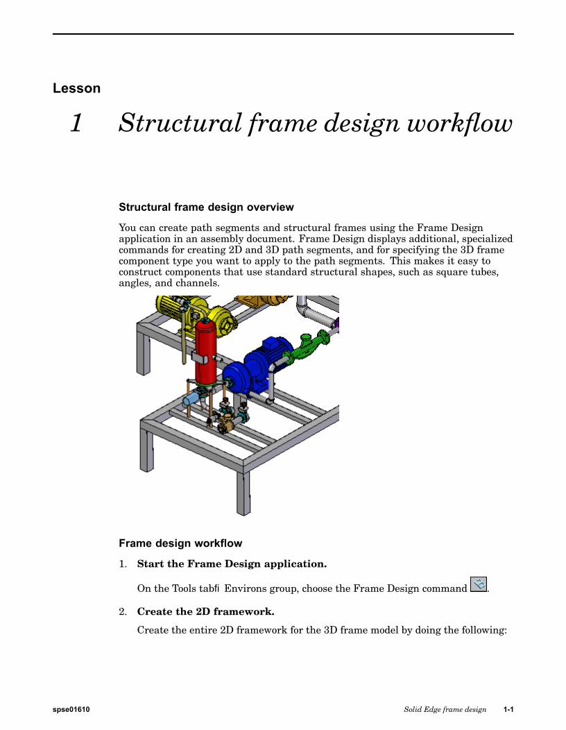
You can create path segments and structural frames using the Frame Designapplication in an assembly document. Frame Design displays additional, specializedcommands for creating 2D and 3D path segments, and for specifying the 3D framecomponent type you want to apply to the path segments. This makes it easy toconstruct components that use standard structural shapes, such as square tubes,angles, and channels.
Frame design workflow
1. Start the Frame Design application.
On the Tools tab®Environs group, choose the Frame Design command .
2. Create the 2D framework.
Create the entire 2D framework for the 3D frame model by doing the following:
spse01610 Solid Edge frame design 1-1

Lesson 1 Structural frame design workflow
a. Use the commands in the Home tab®Segments group to define fullyassociative linear, curved, or bent segment paths for the frame cross sectionto follow.
b. Use the OrientXpres tool to add the 3D connection points to the segments.
1-2 Solid Edge frame design spse01610
Structural frame design workflow
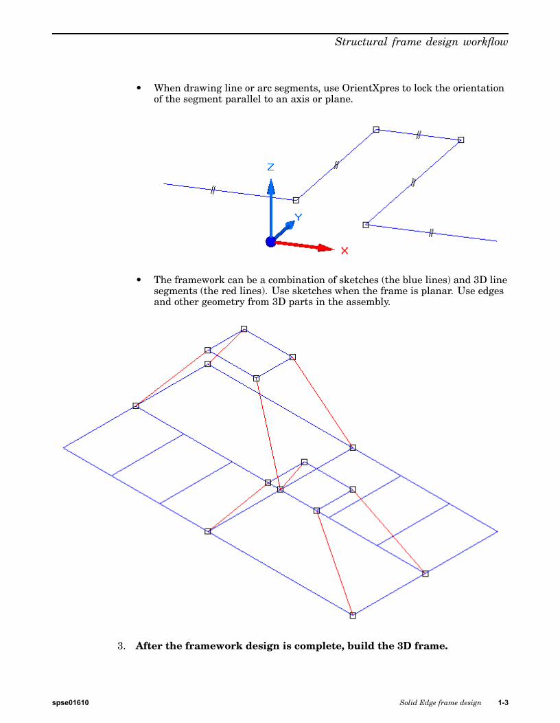
• When drawing line or arc segments, use OrientXpres to lock the orientationof the segment parallel to an axis or plane.
• The framework can be a combination of sketches (the blue lines) and 3D linesegments (the red lines). Use sketches when the frame is planar. Use edgesand other geometry from 3D parts in the assembly.
3. After the framework design is complete, build the 3D frame.
spse01610 Solid Edge frame design 1-3
Lesson 1 Structural frame design workflow
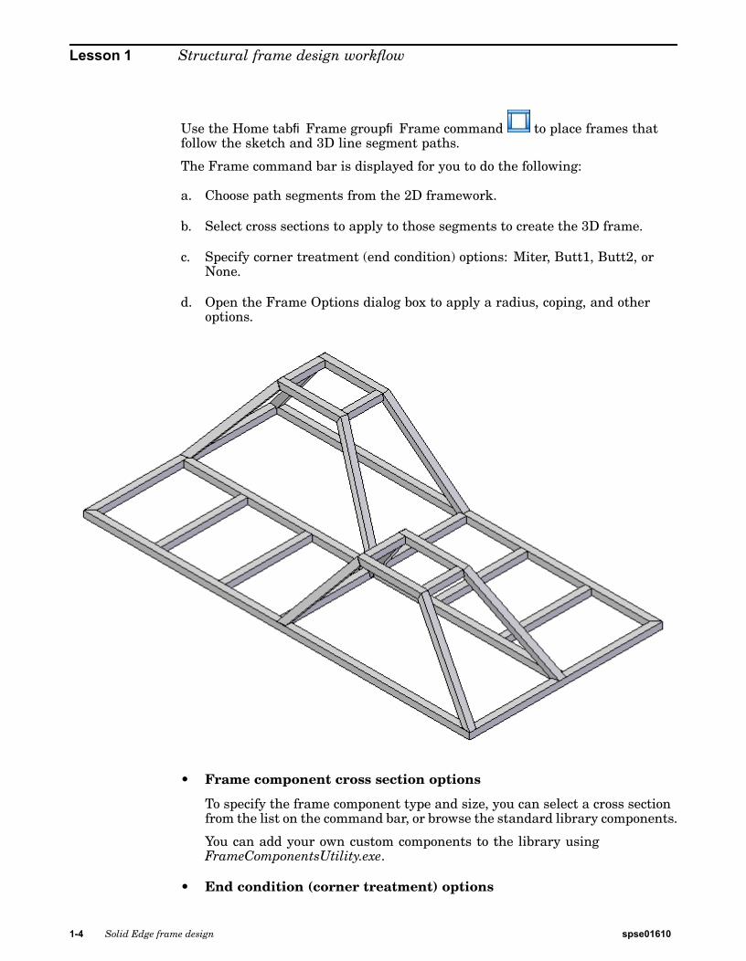
Use the Home tab®Frame group®Frame command to place frames thatfollow the sketch and 3D line segment paths.
The Frame command bar is displayed for you to do the following:
a. Choose path segments from the 2D framework.
b. Select cross sections to apply to those segments to create the 3D frame.
c. Specify corner treatment (end condition) options: Miter, Butt1, Butt2, orNone.
d. Open the Frame Options dialog box to apply a radius, coping, and otheroptions.
• Frame component cross section options
To specify the frame component type and size, you can select a cross sectionfrom the list on the command bar, or browse the standard library components.
You can add your own custom components to the library usingFrameComponentsUtility.exe.
• End condition (corner treatment) options
1-4 Solid Edge frame design spse01610
Structural frame design workflow
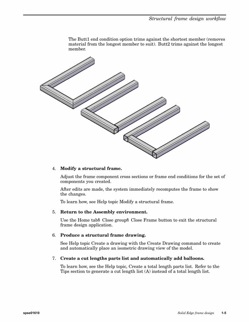
The Butt1 end condition option trims against the shortest member (removesmaterial from the longest member to suit). Butt2 trims against the longestmember.
4. Modify a structural frame.
Adjust the frame component cross sections or frame end conditions for the set ofcomponents you created.
After edits are made, the system immediately recomputes the frame to showthe changes.
To learn how, see Help topic Modify a structural frame.
5. Return to the Assembly environment.
Use the Home tab®Close group®Close Frame button to exit the structuralframe design application.
6. Produce a structural frame drawing.
See Help topic Create a drawing with the Create Drawing command to createand automatically place an isometric drawing view of the model.
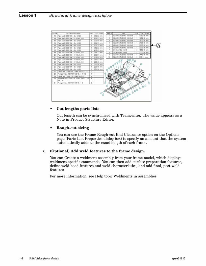
7. Create a cut lengths parts list and automatically add balloons.
To learn how, see the Help topic, Create a total length parts list. Refer to theTips section to generate a cut length list (A) instead of a total length list.
spse01610 Solid Edge frame design 1-5
Lesson 1 Structural frame design workflow
• Cut lengths parts lists
Cut length can be synchronized with Teamcenter. The value appears as aNote in Product Structure Editor.
• Rough-cut sizing
You can use the Frame Rough-cut End Clearance option on the Optionspage (Parts List Properties dialog box) to specify an amount that the systemautomatically adds to the exact length of each frame.
8. (Optional) Add weld features to the frame design.
You can Create a weldment assembly from your frame model, which displaysweldment-specific commands. You can then add surface preparation features,define weld-bead features and weld characteristics, and add final, post-weldfeatures.
For more information, see Help topic Weldments in assemblies.
1-6 Solid Edge frame design spse01610

Structural frame design workflow
Lesson reviewWhat is the frame design workflow
spse01610 Solid Edge frame design 1-7

Lesson 1 Structural frame design workflow
AnswerWhat is the frame design workflow?
1. Start the Frame Design application.
2. Create the 2D framework.
3. After the framework design is complete, build the 3D frame.
4. Modify a structural frame.
5. Return to the Assembly environment.
6. Produce a structural frame drawing.
7. Create a cut lengths parts list and automatically add balloons.
8. (Optional) Add weld features to the frame design.
1-8 Solid Edge frame design spse01610

Structural frame design workflow
Lesson summaryYou can create path segments and structural frames using the Frame Designapplication in an assembly document. Frame Design displays additional, specializedcommands for creating 2D and 3D path segments, and for specifying the 3D framecomponent type you want to apply to the path segments. This makes it easy toconstruct components that use standard structural shapes, such as square tubes,angles, and channels.
spse01610 Solid Edge frame design 1-9

Lesson
2 Starting the frames application
The Frames application is only available from within the Assembly environment.
Procedure for entering and exiting the Frames application
Step 1: Open an assembly file.
Step 2: To start the Frames application, on the Tools tab®Environs group,choose Frame Design .
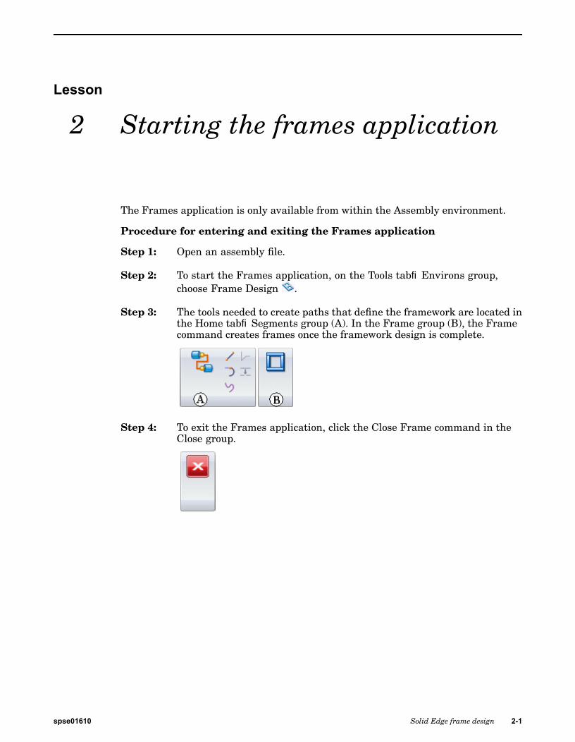
Step 3: The tools needed to create paths that define the framework are located inthe Home tab®Segments group (A). In the Frame group (B), the Framecommand creates frames once the framework design is complete.
Step 4: To exit the Frames application, click the Close Frame command in theClose group.
spse01610 Solid Edge frame design 2-1

Lesson
3 Creating the framework
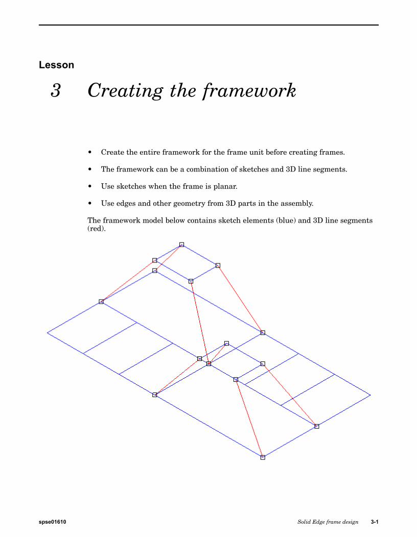
• Create the entire framework for the frame unit before creating frames.
• The framework can be a combination of sketches and 3D line segments.
• Use sketches when the frame is planar.
• Use edges and other geometry from 3D parts in the assembly.
The framework model below contains sketch elements (blue) and 3D line segments(red).
spse01610 Solid Edge frame design 3-1

Lesson 3 Creating the framework
The image below shows square cross sectional frames applied to the framework.
3-2 Solid Edge frame design spse01610
Creating the framework
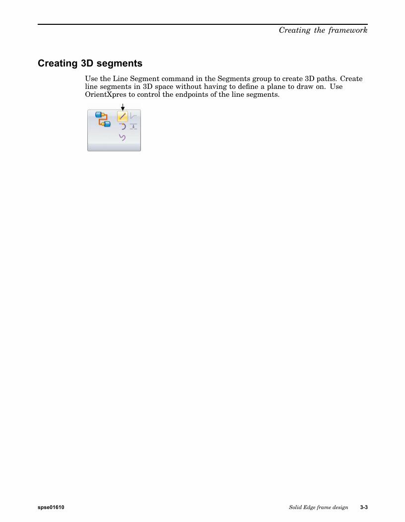
Creating 3D segmentsUse the Line Segment command in the Segments group to create 3D paths. Createline segments in 3D space without having to define a plane to draw on. UseOrientXpres to control the endpoints of the line segments.
spse01610 Solid Edge frame design 3-3

Lesson 3 Creating the framework
OrientXpres tool
The OrientXpres tool is an interactive design aid for drawing lines, arcs, and curvesin 3D space, and for editing the position of BlueDots in 3D space. OrientXpresappears automatically when creating or editing elements which require itscapabilities. For example, OrientXpres appears when drawing line segments inthe XpresRoute and Frame applications, and when editing BlueDots in the Partand Sheet Metal environments.
Note
BlueDots are only available in the ordered modeling environment.
When working in 3D space, you often need to restrict the placement or movement ofelements to be parallel to a particular axis or plane. The OrientXpres tool providesthat capability. You can do the following using OrientXpres:
• To restrict movement parallel to an axis, select one of the three axes (X, Y, or Z).You can also cycle through the axes by typing Z key on the keyboard.
• To restrict movement parallel to a plane, select one of the three planes (XY, YZ,or XZ). You can also cycle through the planes by typing X key on the keyboard.
3-4 Solid Edge frame design spse01610
Creating the framework
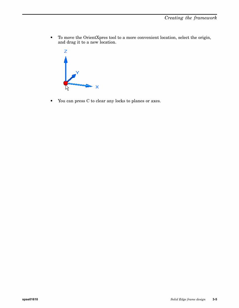
• To move the OrientXpres tool to a more convenient location, select the origin,and drag it to a new location.
• You can press C to clear any locks to planes or axes.
spse01610 Solid Edge frame design 3-5
Lesson 3 Creating the framework
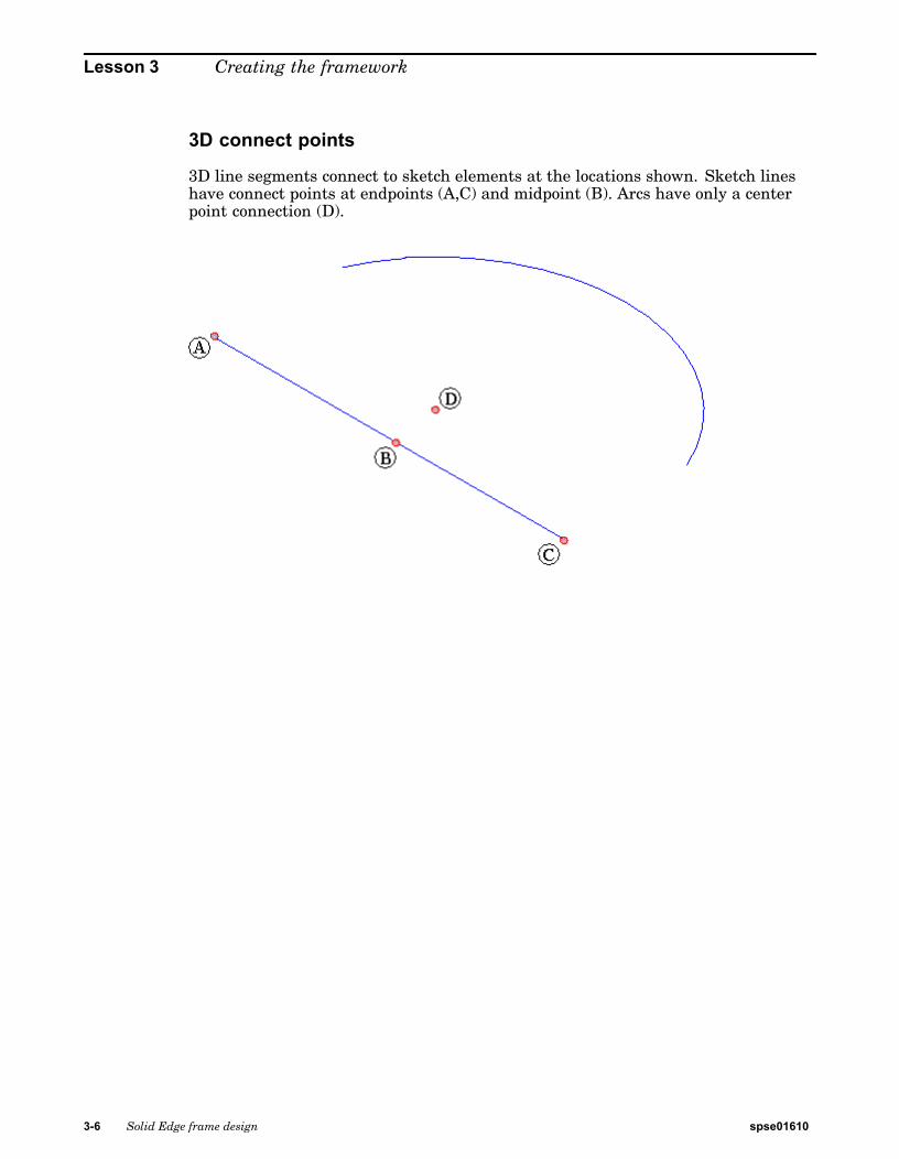
3D connect points
3D line segments connect to sketch elements at the locations shown. Sketch lineshave connect points at endpoints (A,C) and midpoint (B). Arcs have only a centerpoint connection (D).
3-6 Solid Edge frame design spse01610
Creating the framework
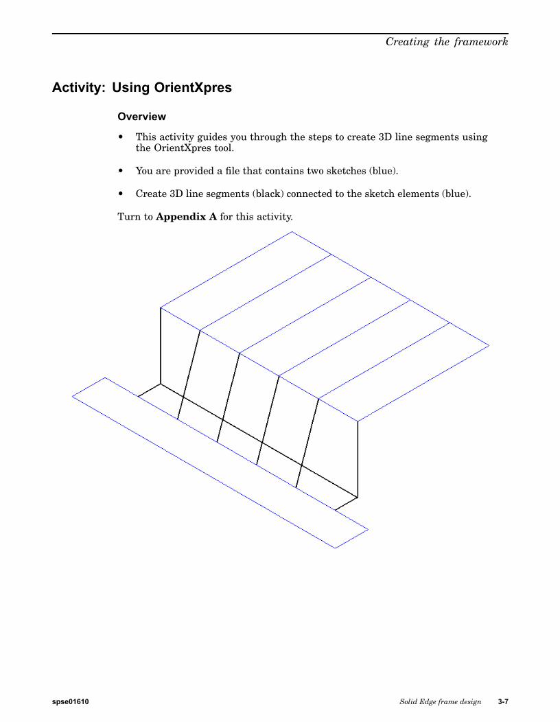
Activity: Using OrientXpres
Overview
• This activity guides you through the steps to create 3D line segments usingthe OrientXpres tool.
• You are provided a file that contains two sketches (blue).
• Create 3D line segments (black) connected to the sketch elements (blue).
Turn to Appendix A for this activity.
spse01610 Solid Edge frame design 3-7

Lesson 3 Creating the framework
Lesson review1. The framework paths can be a combination of what?
2. What tool do you use to create 3D paths?
3-8 Solid Edge frame design spse01610

Creating the framework
Answers1. The framework paths can be a combination of what?
Sketches and 3D line segments
2. What tool do you use to create 3D paths?
OrientXpres
spse01610 Solid Edge frame design 3-9

Lesson 3 Creating the framework
Lesson summaryCreate the entire framework for the frame unit before creating frames. Theframework can be a combination of sketches and 3D line segments. Use sketcheswhen the frame is planar. Use edges and other geometry from 3D parts in theassembly.
3-10 Solid Edge frame design spse01610
Lesson
4 Placing frames
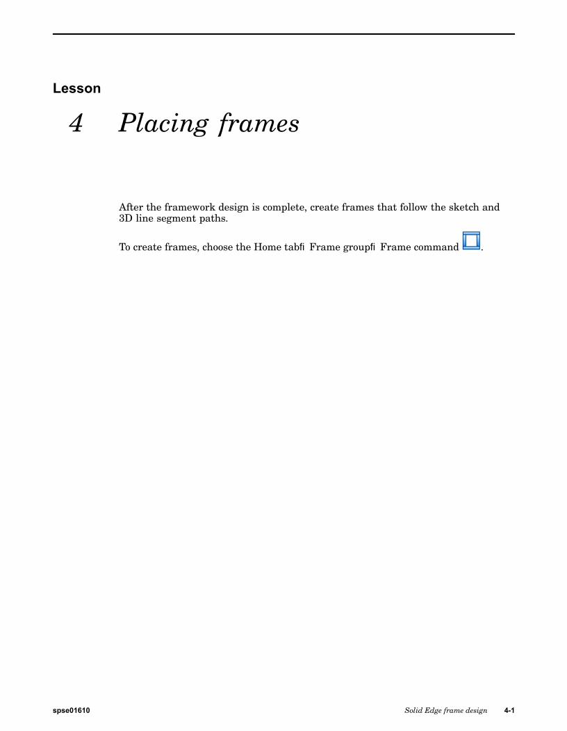
After the framework design is complete, create frames that follow the sketch and3D line segment paths.
To create frames, choose the Home tab®Frame group®Frame command .
spse01610 Solid Edge frame design 4-1

Lesson 4 Placing frames
Frame optionsTo display the Frame Options dialog box, click the Options button on the Framecommand bar.
4-2 Solid Edge frame design spse01610

Placing frames
Corner treatment options
Apply corner treatment
Apply radius
Extend frame component
No corner treatment
spse01610 Solid Edge frame design 4-3
Lesson 4 Placing frames
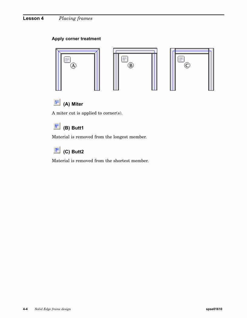
Apply corner treatment
(A) Miter
A miter cut is applied to corner(s).
(B) Butt1
Material is removed from the longest member.
(C) Butt2
Material is removed from the shortest member.
4-4 Solid Edge frame design spse01610
Placing frames
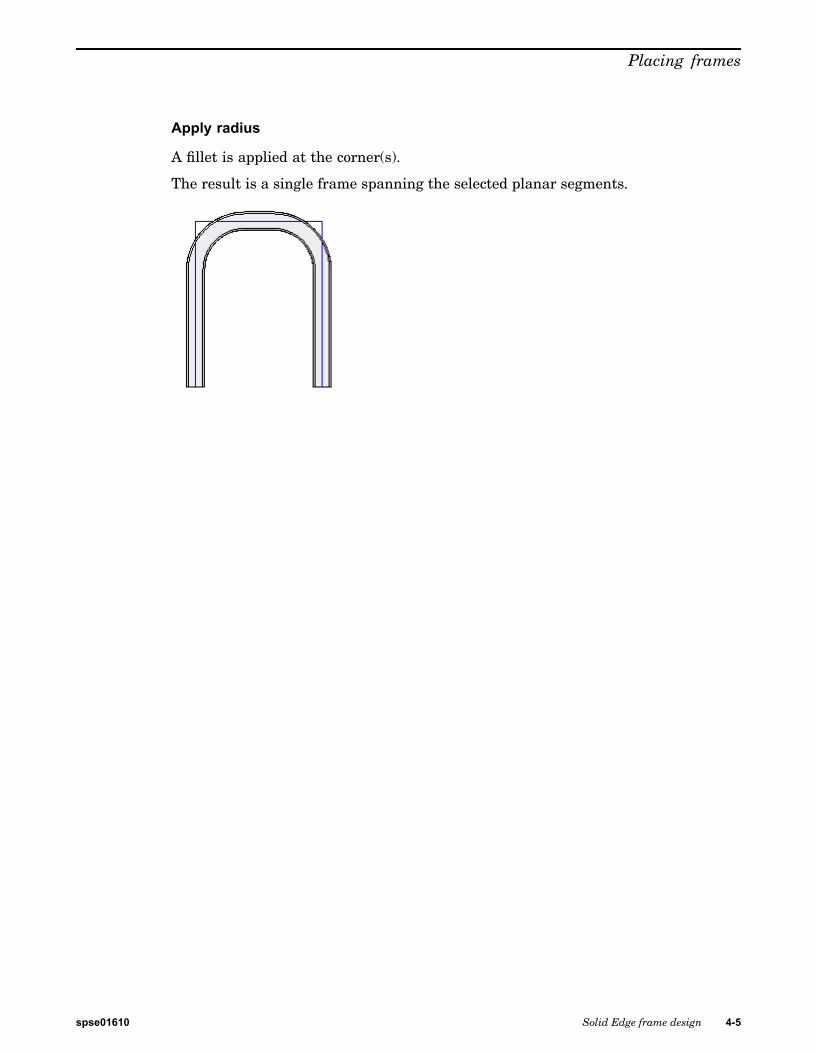
Apply radius
A fillet is applied at the corner(s).
The result is a single frame spanning the selected planar segments.
spse01610 Solid Edge frame design 4-5
Lesson 4 Placing frames
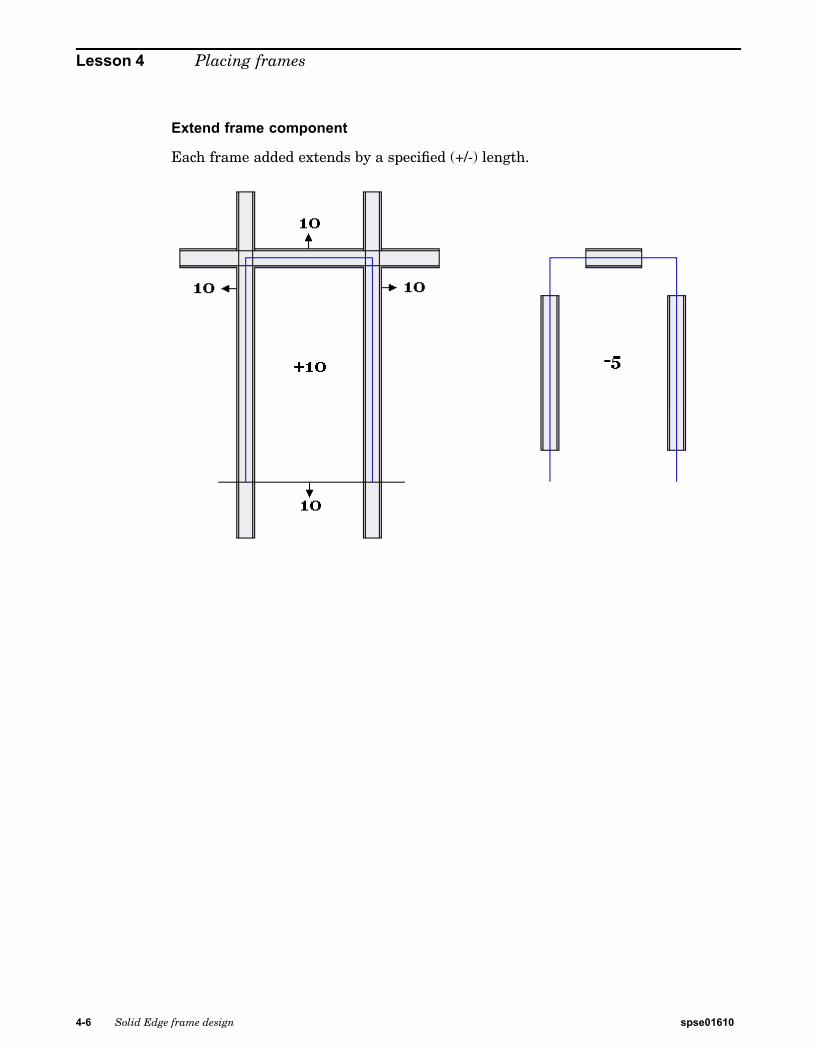
Extend frame component
Each frame added extends by a specified (+/-) length.
4-6 Solid Edge frame design spse01610
Placing frames
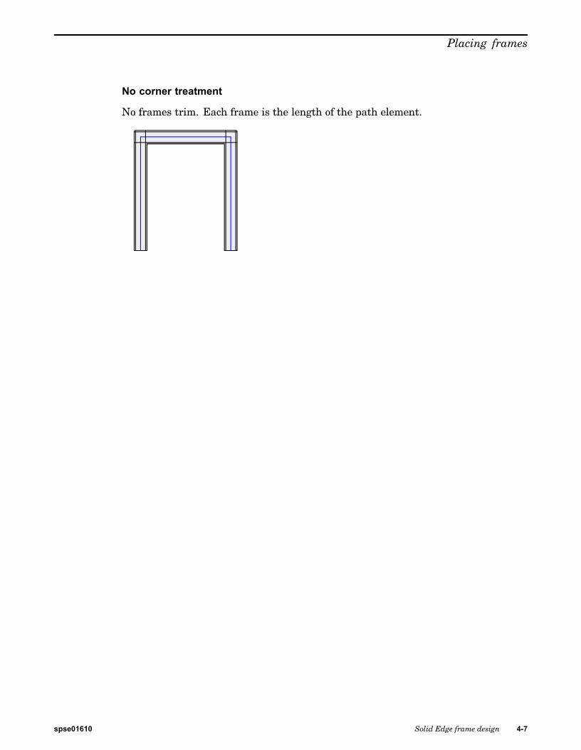
No corner treatment
No frames trim. Each frame is the length of the path element.
spse01610 Solid Edge frame design 4-7
Lesson 4 Placing frames
Frame component location
Frame components reside in unmanaged and managed locations. You can:
• Browse for an unmanaged frame component.
• Select a managed frame component from the Standard Parts Library.
Click the folder icon on the Frame command bar to browse for a framecomponent.
The default folder is controlled from the Applications button®Solid EdgeOptions®File Locations tab.
To change the default frame folder location, select Frame Local Library Folder andthen click Modify.
4-8 Solid Edge frame design spse01610
Placing frames
Browse for component
Store frame components in a common location accessible to all company framedesigners.
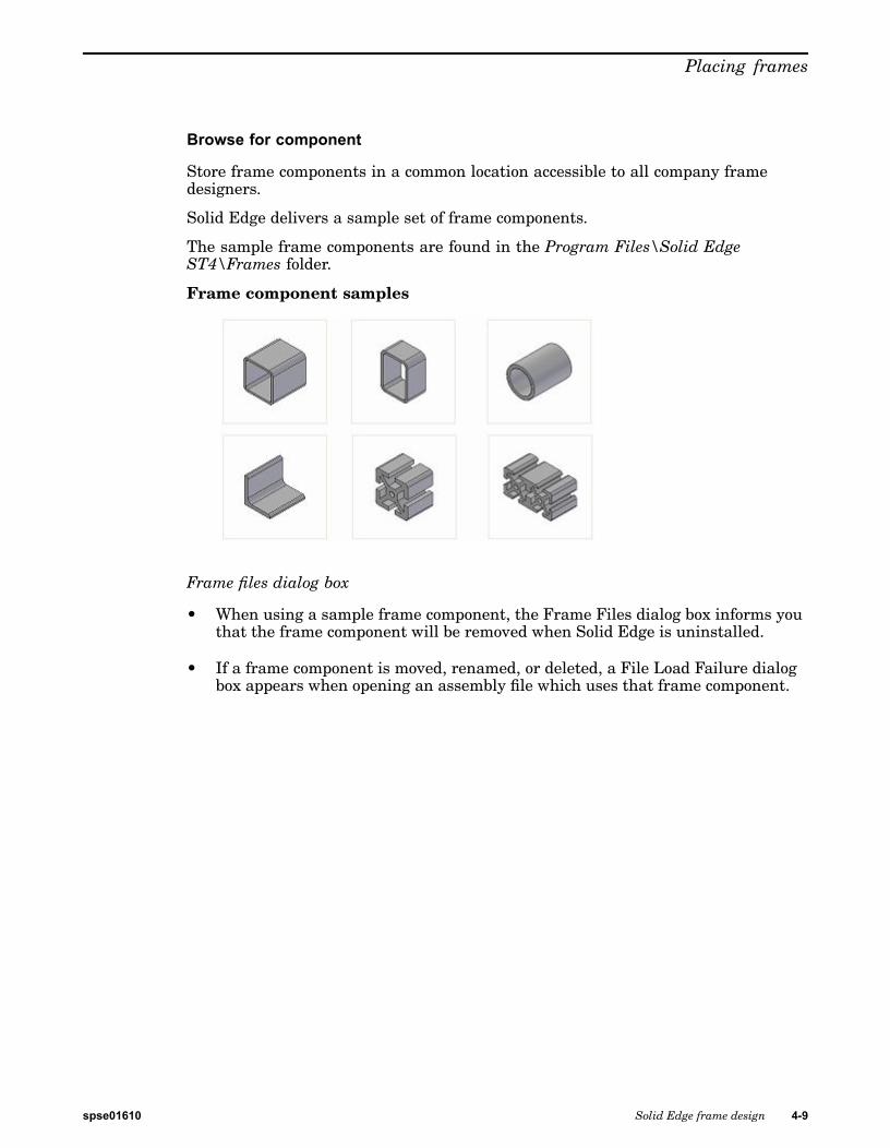
Solid Edge delivers a sample set of frame components.
The sample frame components are found in the Program Files\Solid EdgeST4\Frames folder.
Frame component samples
Frame files dialog box
• When using a sample frame component, the Frame Files dialog box informs youthat the frame component will be removed when Solid Edge is uninstalled.
• If a frame component is moved, renamed, or deleted, a File Load Failure dialogbox appears when opening an assembly file which uses that frame component.
spse01610 Solid Edge frame design 4-9
Lesson 4 Placing frames
Frames command bar• Choose the Frame command and the Frame command bar appears.
• The Frame Options dialog box displays for you to accept or change the activesettings.
• The automatic display of the dialog box can be turned off.
• The dialog box can be shown at any time by clicking the Options button on thecommand bar.
4-10 Solid Edge frame design spse01610
Placing frames
Select path step
• The Frame Options button is available at all times within the Frame command.
• The first step in the Frame command is the Select Path Step.
• While in the Path Selection Step, browse for a frame component or select acomponent from the Recently Used Component list.
• You have the option to select single path elements or to select a chain of pathelements.
• When you select the path elements, click the Frame Accept button. Deselect theselected path elements by clicking the Frame Deselect button.
• The frames place after accepting the paths.
• Click Finish to end the Frame component placement step.
Note
The Frame command remains active to continue placing frames.
spse01610 Solid Edge frame design 4-11
Lesson 4 Placing frames
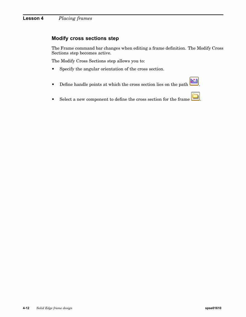
Modify cross sections step
The Frame command bar changes when editing a frame definition. The Modify CrossSections step becomes active.
The Modify Cross Sections step allows you to:
• Specify the angular orientation of the cross section.
• Define handle points at which the cross section lies on the path .
• Select a new component to define the cross section for the frame .
4-12 Solid Edge frame design spse01610
Placing frames
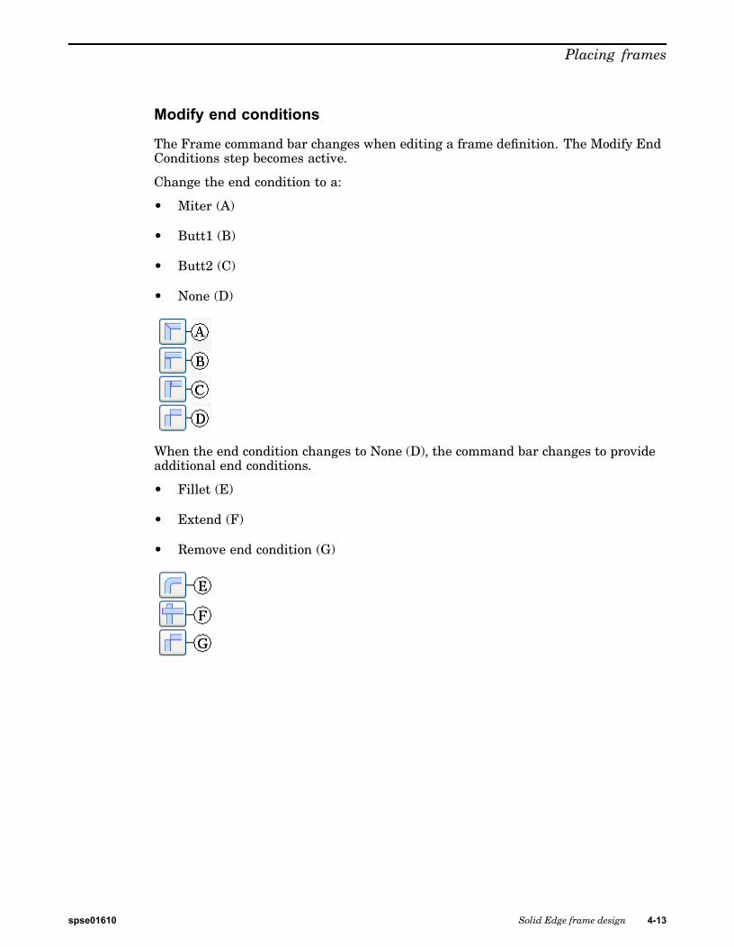
Modify end conditions
The Frame command bar changes when editing a frame definition. The Modify EndConditions step becomes active.
Change the end condition to a:
• Miter (A)
• Butt1 (B)
• Butt2 (C)
• None (D)
When the end condition changes to None (D), the command bar changes to provideadditional end conditions.
• Fillet (E)
• Extend (F)
• Remove end condition (G)
spse01610 Solid Edge frame design 4-13
Lesson 4 Placing frames
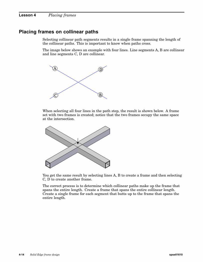
Placing frames on collinear pathsSelecting collinear path segments results in a single frame spanning the length ofthe collinear paths. This is important to know when paths cross.
The image below shows an example with four lines. Line segments A, B are collinearand line segments C, D are collinear.
When selecting all four lines in the path step, the result is shown below. A frameset with two frames is created; notice that the two frames occupy the same spaceat the intersection.
You get the same result by selecting lines A, B to create a frame and then selectingC, D to create another frame.
The correct process is to determine which collinear paths make up the frame thatspans the entire length. Create a frame that spans the entire collinear length.Create a single frame for each segment that butts up to the frame that spans theentire length.
4-14 Solid Edge frame design spse01610
Placing frames
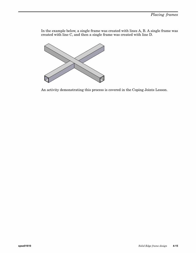
In the example below, a single frame was created with lines A, B. A single frame wascreated with line C, and then a single frame was created with line D.
An activity demonstrating this process is covered in the Coping Joints Lesson.
spse01610 Solid Edge frame design 4-15
Lesson 4 Placing frames
Activity: Corner treatment options
Overview
In this activity, use each of the corner treatment options to observe the results.
Turn to Appendix B for this activity.
4-16 Solid Edge frame design spse01610
Placing frames
Activity: Dune buggy frame
Overview
In this activity, create a dune buggy frame. The paths are defined. All of the pathsare 3D lines and arcs. Use a round tubing component. The handle point for theround component cross section is the center point. Round cross sections usuallyproduce the desired results at initial placement. No frame repositioning is needed.
Turn to Appendix C for this activity.
spse01610 Solid Edge frame design 4-17

Lesson 4 Placing frames
Lesson review1. What are the four corner treatment options?
2. Name the three corner treatments and give a brief description of each.
3. Where are the sample frame components found?
4. What is the first step in the Frame command?
5. What controls where a frame component positions on the path?
6. How do you change how a frame positions on a path?
4-18 Solid Edge frame design spse01610
Placing frames
Answers1. What are the four corner treatment options?
Apply corner treatment.
Apply radius.
Extend frame component.
No corner treatment.
2. Name the three corner treatments and give a brief description of each.
Miter - A miter cut is applied to corner(s).
Butt1 - Material is removed from the longest member.
Butt2 - Material is removed from the shortest member.
3. Where are the sample frame components found?
Program Files\Solid Edge ST4\Frames folder
4. What is the first step in the Frame command?
Select path.
5. What controls where a frame component positions on the path?
When a frame component is created, you can define a default snap point. Theframe snap point lies on the path.
If a snap point does not exist in the frame component file, the Frame commanddefaults to the centroid of the 2D cross section.
6. How do you change how a frame positions on a path?
On the frame command bar, click the Modify cross sections option. Click thedefine handle point and then select a new handle point on the cross section.
spse01610 Solid Edge frame design 4-19
Lesson 4 Placing frames
Lesson summaryAfter the framework design is complete, create frames that follow the sketch and3D line segment paths.
To create frames, choose the Frame command in the Frame group. You can editframe components, frame end conditions, paths and frame positions from the framecommand bar.
4-20 Solid Edge frame design spse01610
Lesson
5 Automatic frame componentpositioning
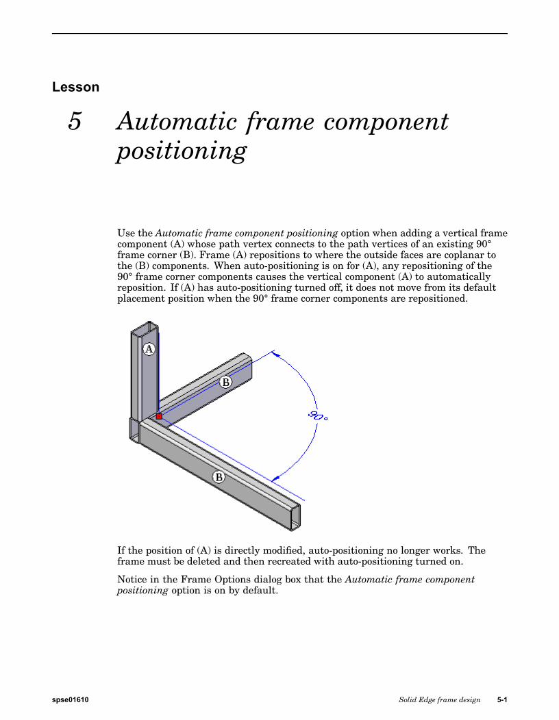
Use the Automatic frame component positioning option when adding a vertical framecomponent (A) whose path vertex connects to the path vertices of an existing 90°frame corner (B). Frame (A) repositions to where the outside faces are coplanar tothe (B) components. When auto-positioning is on for (A), any repositioning of the90° frame corner components causes the vertical component (A) to automaticallyreposition. If (A) has auto-positioning turned off, it does not move from its defaultplacement position when the 90° frame corner components are repositioned.
If the position of (A) is directly modified, auto-positioning no longer works. Theframe must be deleted and then recreated with auto-positioning turned on.
Notice in the Frame Options dialog box that the Automatic frame componentpositioning option is on by default.
spse01610 Solid Edge frame design 5-1

Lesson 5 Automatic frame component positioning
Activity: Automatic frame positioning
Overview
In this activity, create frames and observe the auto-positioning behavior.
Turn to Appendix D for this activity.
5-2 Solid Edge frame design spse01610
Lesson
6 Editing frames
Edit a frame definition during creation or after the frame command is finished.
Edit frame paths, position, end conditions and component type.
PathFinder
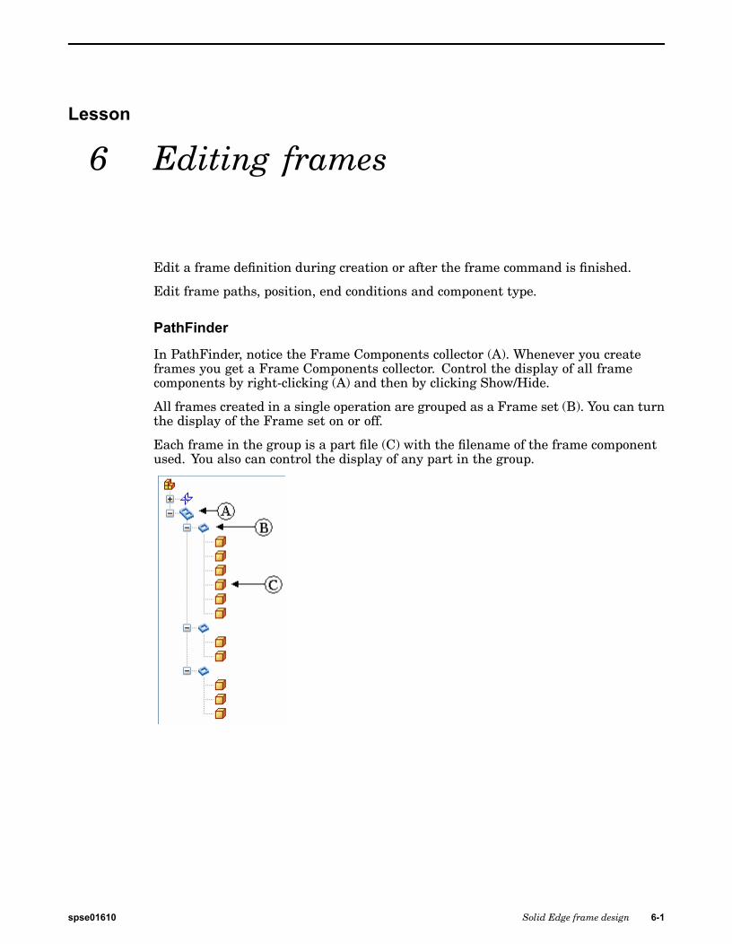
In PathFinder, notice the Frame Components collector (A). Whenever you createframes you get a Frame Components collector. Control the display of all framecomponents by right-clicking (A) and then by clicking Show/Hide.
All frames created in a single operation are grouped as a Frame set (B). You can turnthe display of the Frame set on or off.
Each frame in the group is a part file (C) with the filename of the frame componentused. You also can control the display of any part in the group.
spse01610 Solid Edge frame design 6-1
Lesson 6 Editing frames
Edit definition processTo edit a frame:
Step 1: Click the Select tool .
Step 2: In PathFinder, click the Frame group to edit.
Step 3: Choose the Edit Definition command.
Two methods are available for selecting frames to edit:
(Method 1) Right-click the Frame set or a member of the frame setin PathFinder, and then click Edit Definition.
(Method 2) Right-click the frame in the assembly window, and thenclick Edit Definition.
6-2 Solid Edge frame design spse01610
Editing frames
Editing frame pathsAdd or remove paths from the frame definition.
To edit a path definition:
Step 1: Within the Edit Definition command, click the Select Path Step.
Step 2: To add a path segment, select one or more paths. The selected pathhighlights along with the other paths in the frame path definition.
Step 3: Click the Accept button or right-click to complete the path step.
Step 4: To remove a path segment, press the Ctrl key and select the path. Theselected path no longer highlights.
Step 5: Click the Accept button or right-click to complete the path step.
Note
You can add and remove path segments in the same step.
spse01610 Solid Edge frame design 6-3
Lesson 6 Editing frames
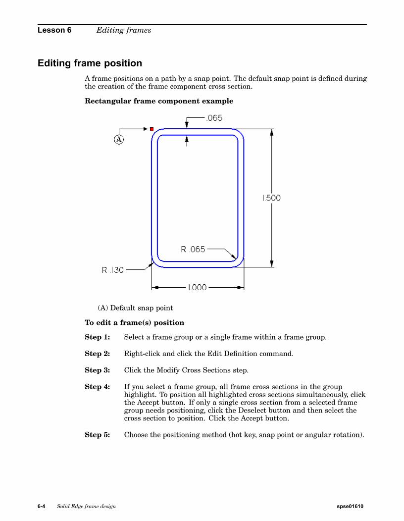
Editing frame positionA frame positions on a path by a snap point. The default snap point is defined duringthe creation of the frame component cross section.
Rectangular frame component example
(A) Default snap point
To edit a frame(s) position
Step 1: Select a frame group or a single frame within a frame group.
Step 2: Right-click and click the Edit Definition command.
Step 3: Click the Modify Cross Sections step.
Step 4: If you select a frame group, all frame cross sections in the grouphighlight. To position all highlighted cross sections simultaneously, clickthe Accept button. If only a single cross section from a selected framegroup needs positioning, click the Deselect button and then select thecross section to position. Click the Accept button.
Step 5: Choose the positioning method (hot key, snap point or angular rotation).
6-4 Solid Edge frame design spse01610
Editing frames
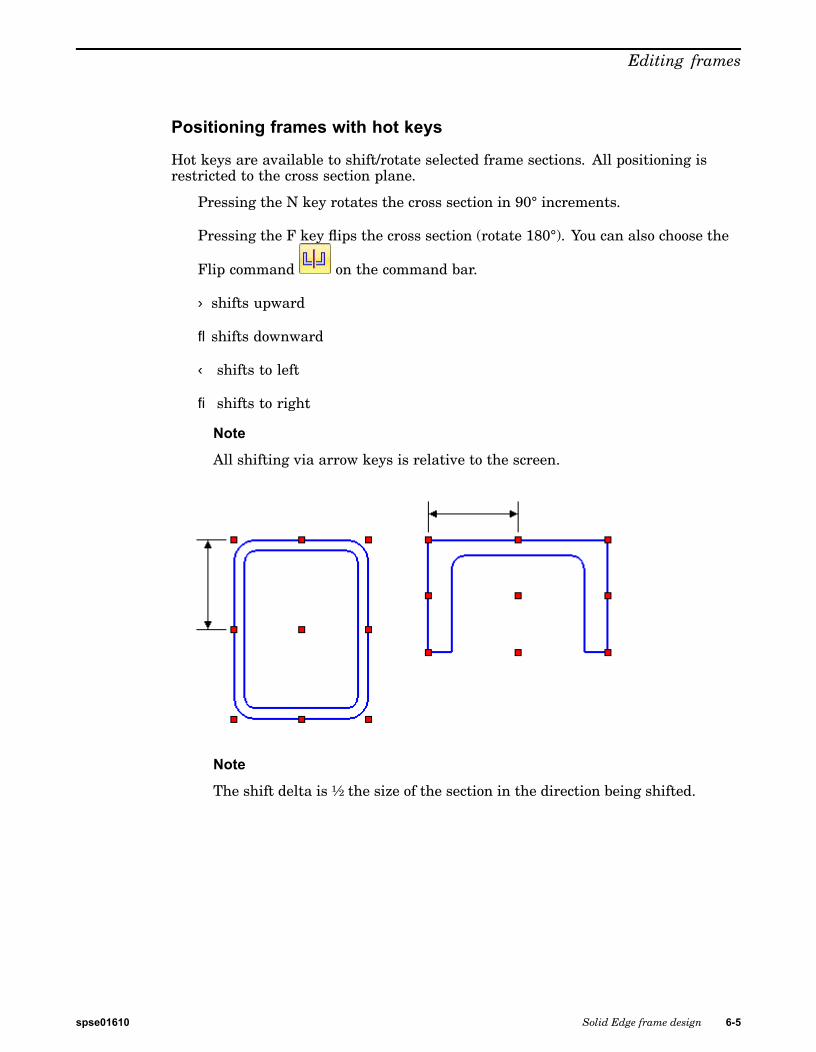
Positioning frames with hot keys
Hot keys are available to shift/rotate selected frame sections. All positioning isrestricted to the cross section plane.
Pressing the N key rotates the cross section in 90° increments.
Pressing the F key flips the cross section (rotate 180°). You can also choose the
Flip command on the command bar.
shifts upward
¯ shifts downward
¬ shifts to left
® shifts to right
Note
All shifting via arrow keys is relative to the screen.
Note
The shift delta is ½ the size of the section in the direction being shifted.
spse01610 Solid Edge frame design 6-5
Lesson 6 Editing frames
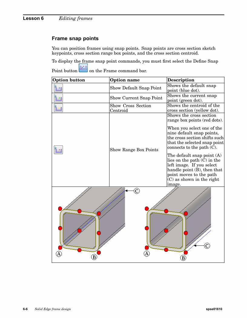
Frame snap points
You can position frames using snap points. Snap points are cross section sketchkeypoints, cross section range box points, and the cross section centroid.
To display the frame snap point commands, you must first select the Define Snap
Point button on the Frame command bar.
Option button Option name Description
Show Default Snap Point Shows the default snappoint (blue dot).
Show Current Snap Point Shows the current snappoint (green dot).
Show Cross SectionCentroid
Shows the centroid of thecross section (yellow dot).
Show Range Box Points
Shows the cross sectionrange box points (red dots).
When you select one of thenine default snap points,the cross section shifts suchthat the selected snap pointconnects to the path (C).
The default snap point (A)lies on the path (C) in theleft image. If you selecthandle point (B), then thatpoint moves to the path(C) as shown in the rightimage.
6-6 Solid Edge frame design spse01610
Editing frames
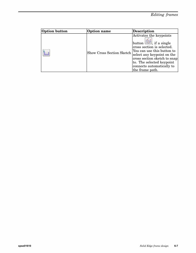
Option button Option name Description
Show Cross Section Sketch
Activates the keypoints
button , if a singlecross section is selected.You can use this button toselect any keypoint on thecross section sketch to snapto. The selected keypointconnects automatically tothe frame path.
spse01610 Solid Edge frame design 6-7
Lesson 6 Editing frames
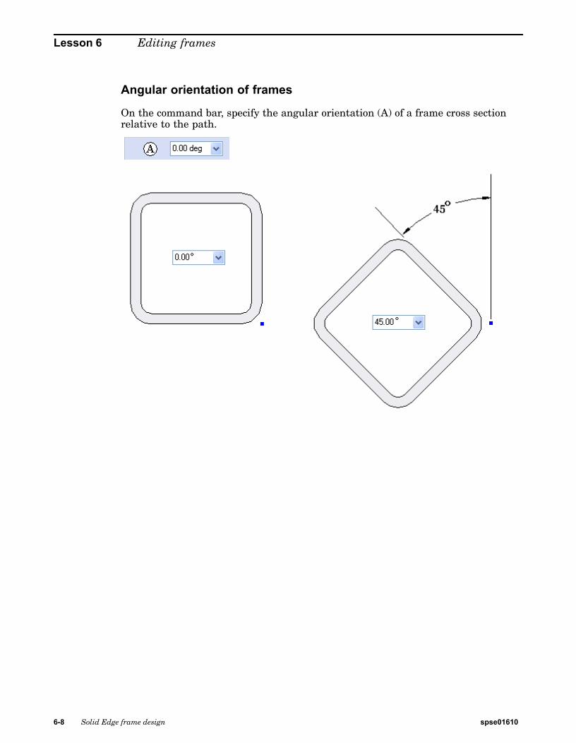
Angular orientation of frames
On the command bar, specify the angular orientation (A) of a frame cross sectionrelative to the path.
6-8 Solid Edge frame design spse01610
Editing frames
Editing frame componentsSelect a new frame cross section for an entire frame set or selected frames. Changecross sections in the Modify Cross Sections step.
Once you select the frames, click the Accept button.
Click the Select New Cross Section Component button .
The file Open dialog box or the standard parts interface (depending upon whichoption is set) appears.
Select the new size of the cross section or select a different type or size.
The default location to begin browsing for frame components is Program Files®SolidEdge ST4®Frames.
In the Open dialog, select the component file and then click the Open button. Theframes update with the new component.
Note
Notice the Frame Files message.
spse01610 Solid Edge frame design 6-9
Lesson 6 Editing frames
Editing frame end conditionsEdit the end conditions of adjacent frame components. On the Frame command bar,click the Modify End Conditions step.
Select the vertex of adjacent frame components to modify end condition betweencomponents. You can select more than one vertex. To edit the end conditions of theselected vertices, click the Accept button.
Click the new end condition and the modification is applied. Edit additional endconditions by clicking the Modify End Conditions step again. When all end conditionmodifications are complete, click Finish.
6-10 Solid Edge frame design spse01610
Editing frames
Editing frames activities
Overview
In these activities, edit an existing frame model. Edit frame paths, position, endconditions and components.
Editing a corner treatment
Turn to Appendix E for this activity.
Editing a path definition
Turn to Appendix F for this activity.
Editing a single vertex
Turn to Appendix G for this activity.
Editing frame position using hot keys
Turn to Appendix H for this activity.
Editing frame position using snap points
Turn to Appendix I for this activity.
Editing frame components
Turn to Appendix J for this activity.
Editing frame cross section orientation
Turn to Appendix K for this activity.
Activities summary
You can edit any step in the creation of frames. So do not worry if you do not get theresults desired in the initial placement. Making changes is easy to do.
spse01610 Solid Edge frame design 6-11

Lesson 6 Editing frames
Lesson review1. What is the edit definition process for frames?
2. Name the ways to reposition a frame on a path.
6-12 Solid Edge frame design spse01610
Editing frames
Answers1. What is the edit definition process for frames?
Step 1: Click the Select tool.
Step 2: In PathFinder, click the Frame group to edit.
Step 3: Choose the Edit Definition command.
There are two methods available for selecting the Edit Definitioncommand.
(Method 1) Right-click on the Frame set or a member of the frameset in PathFinder and then click Edit Definition.
(Method 2) Right-click on the frame in the assembly window andthen click Edit Definition.
2. Name the ways to reposition a frame on a path.
Using hot keys, snap points or by an angular rotation
spse01610 Solid Edge frame design 6-13

Lesson 6 Editing frames
Lesson summaryYou can edit a frame definition during creation or after the frame command isfinished.
You can modify frame paths, position, end conditions and component type.
6-14 Solid Edge frame design spse01610
Lesson
7 Coping joints
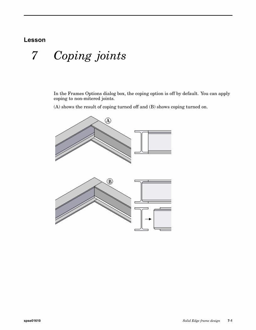
In the Frames Options dialog box, the coping option is off by default. You can applycoping to non-mitered joints.
(A) shows the result of coping turned off and (B) shows coping turned on.
spse01610 Solid Edge frame design 7-1

Lesson 7 Coping joints
Activity: Coping joints and collinear paths
Overview
In this activity, use the coping non-mitered joints option. You also learn how tohandle collinear path segments.
Turn to Appendix L for this activity.
7-2 Solid Edge frame design spse01610
Lesson
8 Creating custom framecomponents
Create frames using delivered frame components or frame components from theStandard Parts Library. A user-defined frame component can be used. This lessoncovers the process of creating custom frame components.
spse01610 Solid Edge frame design 8-1
Lesson 8 Creating custom frame components
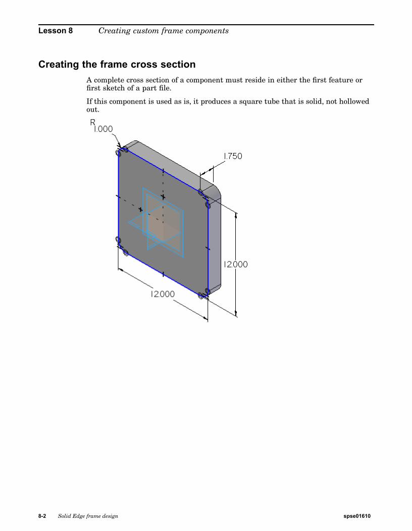
Creating the frame cross sectionA complete cross section of a component must reside in either the first feature orfirst sketch of a part file.
If this component is used as is, it produces a square tube that is solid, not hollowedout.
8-2 Solid Edge frame design spse01610

Creating custom frame components
This component produces the intended hollow, square tubing.
spse01610 Solid Edge frame design 8-3
Lesson 8 Creating custom frame components
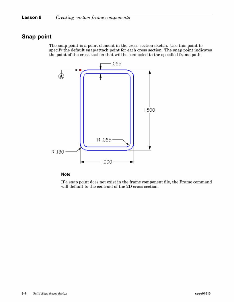
Snap pointThe snap point is a point element in the cross section sketch. Use this point tospecify the default snap/attach point for each cross section. The snap point indicatesthe point of the cross section that will be connected to the specified frame path.
Note
If a snap point does not exist in the frame component file, the Frame commandwill default to the centroid of the 2D cross section.
8-4 Solid Edge frame design spse01610
Creating custom frame components
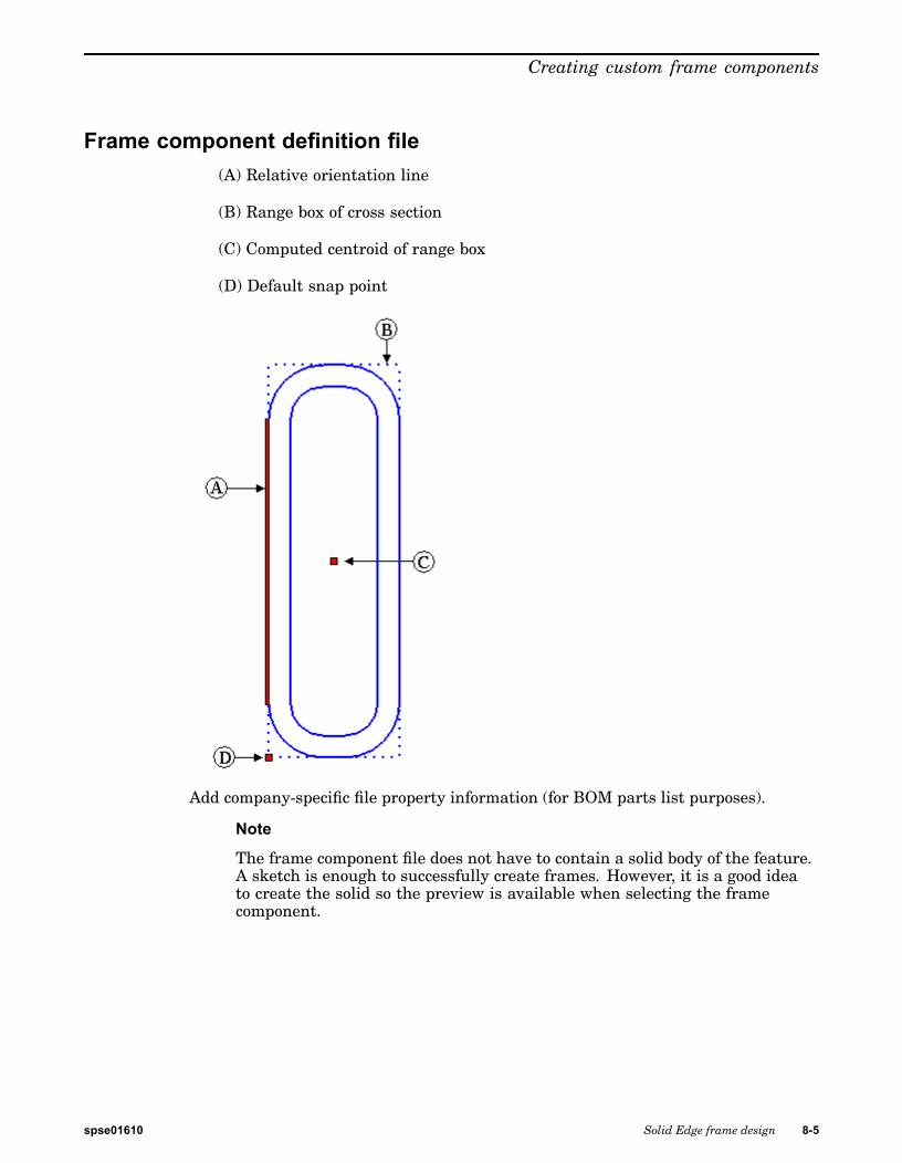
Frame component definition file(A) Relative orientation line
(B) Range box of cross section
(C) Computed centroid of range box
(D) Default snap point
Add company-specific file property information (for BOM parts list purposes).
Note
The frame component file does not have to contain a solid body of the feature.A sketch is enough to successfully create frames. However, it is a good ideato create the solid so the preview is available when selecting the framecomponent.
spse01610 Solid Edge frame design 8-5
Lesson 8 Creating custom frame components
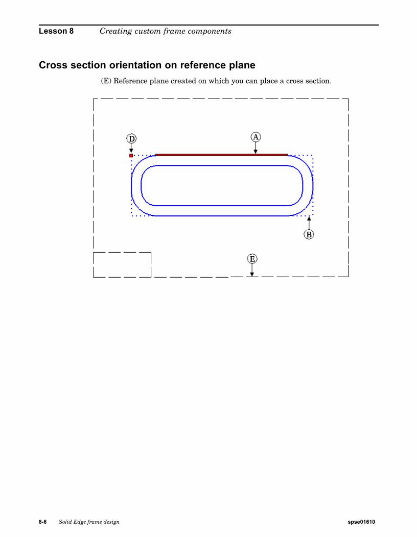
Cross section orientation on reference plane(E) Reference plane created on which you can place a cross section.
8-6 Solid Edge frame design spse01610
Creating custom frame components
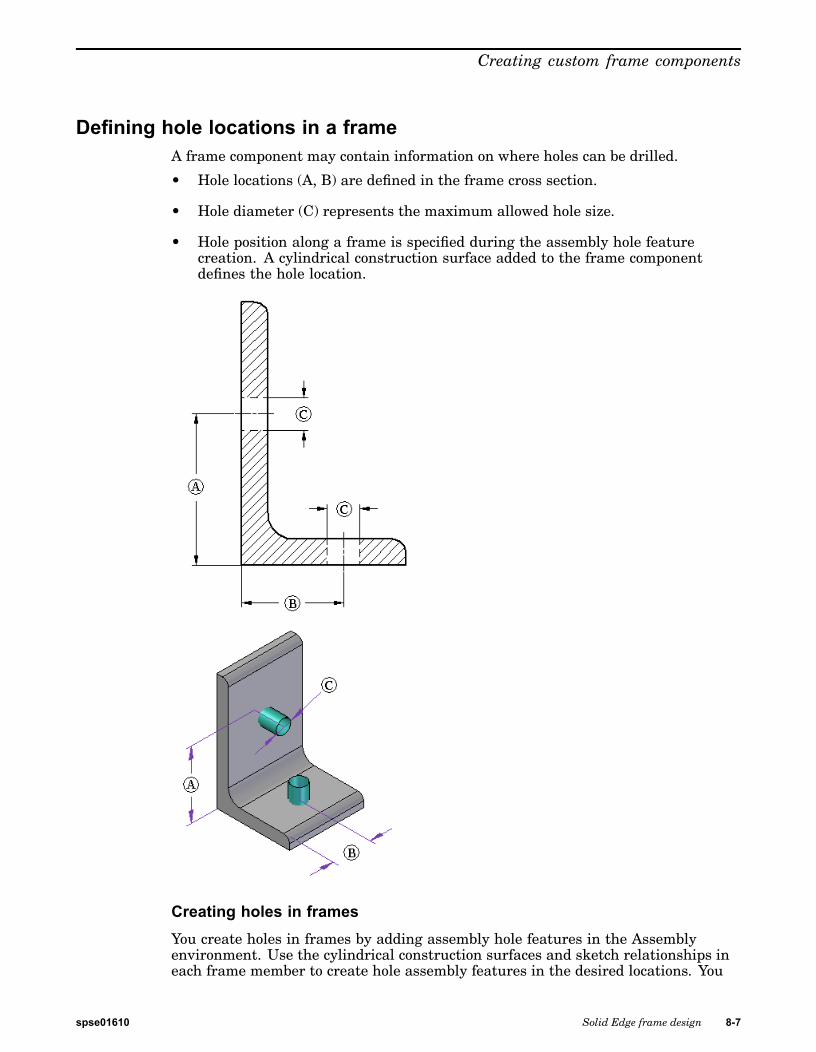
Defining hole locations in a frameA frame component may contain information on where holes can be drilled.
• Hole locations (A, B) are defined in the frame cross section.
• Hole diameter (C) represents the maximum allowed hole size.
• Hole position along a frame is specified during the assembly hole featurecreation. A cylindrical construction surface added to the frame componentdefines the hole location.
Creating holes in framesYou create holes in frames by adding assembly hole features in the Assemblyenvironment. Use the cylindrical construction surfaces and sketch relationships ineach frame member to create hole assembly features in the desired locations. You
spse01610 Solid Edge frame design 8-7
Lesson 8 Creating custom frame components
can use the Include command to include edges from the construction surfaces to aidin aligning the assembly hole features.
If hole location construction surfaces exist in the cross section component file, theydo not appear on the frame members by default when the frame is created. You mustuse the Hole Location®Retrieve from Cross Section Component command on theframe shortcut menu to bring these surfaces into the frame.
Removing the construction surfaces from the frame
You can hide construction surfaces by choosing the Show/Hide Component®Surfacescommand on the shortcut menu.
You also can delete the construction surfaces from the frame by choosing the HoleLocation®Delete from Frame command on the shortcut menu. Use the Retrievefrom Cross Section Component command to restore them if needed.
8-8 Solid Edge frame design spse01610

Creating custom frame components
Applying frame attributesOnce the custom frame cross section is defined, the next step is to apply frameattributes. You must be in the profile or sketch environment of the user-definedcross section.
To apply frame attributes, click Applications®Run Macro.
In the Run Macro dialog box, select the file FrameComponentsUtility.exe located inthe Program Files/Solid Edge ST4/Frames folder. Click Open.
Frame utility location
Program Files\Solid Edge ST4\Frames\Frame Component Utility
spse01610 Solid Edge frame design 8-9
Lesson 8 Creating custom frame components
Frame components utility process
Step 1: Click the profile point to be defined as the handle point.
Step 2: Click the profile line to be defined as the relative orientation.
Note
Steps 1 and 2 are order-independent as long as you complete steps1 and 2. This must be done for both handle point and orientationline for non-circular cross sections. Each section must have nomore than one handle point and one orientation line defined.
Step 3: Click Step 3 in the Frame Component Utility. The profile point and lineshould highlight to verify appropriate attributes have been selected.
Step 4: Click Quit to complete the addition of attributes to the cross section.
The Delete ALL Frame attributes on profile elements button scans the current profileand deletes all of the existing frame attributes that may have been previouslycreated.
The user-defined frame component is now ready for use.
8-10 Solid Edge frame design spse01610

Creating custom frame components
Activity: Creating a custom frame
Overview
In this activity, create a custom frame.
Turn to Appendix M for this activity.
spse01610 Solid Edge frame design 8-11
Lesson 8 Creating custom frame components
Lesson review1. When creating a custom frame, what is required to define the cross section?
2. If no snap is in the frame definition, where does the frame position on a path?
3. What is the advantage of creating a custom frame using a feature instead of asketch cross section?
4. When the custom frame cross section is complete, how do you apply the frameattributes to create a new frame?
8-12 Solid Edge frame design spse01610
Creating custom frame components
Answers1. When creating a custom frame, what is required to define the cross section?
A complete cross section of component must reside in either the first featureor first sketch of a part file.
2. If no snap is in the frame definition, where does the frame position on a path?
The centroid of the cross section.
3. What is the advantage of creating a custom frame using a feature instead of asketch cross section?
The frame component file does not have to contain a solid body of the feature.A sketch is enough to successfully create frames. However, it is a good idea tocreate the solid so the preview is available when selecting the frame component.
4. When the custom frame cross section is complete, how do you apply the frameattributes to create a new frame?
You must be in the profile or sketch environment of the user-defined cross section.
To apply frame attributes, click Applications®Run Macro.
In the Run Macro dialog, select the file FrameComponentsUtility.exe located inthe Program Files/Solid Edge ST4/Frames folder. Click Open.
The Frame utility location is®Program Files\Solid Edge ST4\Frames\FrameComponent Utility.
spse01610 Solid Edge frame design 8-13

Lesson 8 Creating custom frame components
Lesson summaryYou create frames using delivered frame components or frame components from theStandard Parts Library. A user-defined frame component can be used. This lessoncovered the process of creating custom frame components.
8-14 Solid Edge frame design spse01610
Lesson
9 Drafting
The process of creating drawings of 3D frames is the same as creating 3D assemblydrawings.
We cover the parts list features that pertain to frames in an activity.
To learn more about parts lists, see the following Help topics:
• Parts lists
• Exploded parts lists
• Using the Columns tab
• Using the Options tab
In this activity, create a parts list that includes cut lengths for each component andchoose how you want to organize the list for downstream viewers in manufacturingor purchasing. Create a parts list using rough-cut sizing, where you specify anamount that the system automatically adds to the exact length of frame. The lastparts list includes the total length of each frame component.
Turn to Appendix N for this activity.
spse01610 Solid Edge frame design 9-1

Lesson
10 Saving frame components
You can save a frame entity non-associatively to either a part or assembly file.
Saving a single frame entity
Step 1: In the frame section of Assembly PathFinder, right-click a single entity.
Step 2: On the shortcut menu, click Save As and on the Save As dialog box,specify a folder and name for the entity.
The frame entity is not associative. Opening the saved entity file showsthat the frame is a body feature not linked to the original model.
Saving a frame set
Step 1: In the frame section of Assembly PathFinder, right-click a frame set.
Step 2: On the shortcut menu, click Save As and on the Save As dialog box,specify a folder and name for the frame set. The frame set name is thedefault filename for the save as assembly file.
The frame set is not associative. Notice when the Save As assembly(i.e. Frame_5.asm) opens that the components from the original file arecopied and renamed.
Save a single frame component associatively with the Save Selected Model command.
Step 1: Choose Application button®Save As®Save Selected Model.
Step 2: Select a frame entity to be saved to the file.
Step 3: Enter a filename and folder for the saved model.
When the saved model opens, notice that the geometry of the framecomes in as a linked part copy . Any change made to the originalframe entity reflects in the saved model.
spse01610 Solid Edge frame design 10-1


A Activity: Using OrientXpres
Step 1
▸ Open orientxpres.asm.
spse01610 Solid Edge frame design A-1
A Activity: Using OrientXpres
Step 2Start the Frames application.
▸ On the Tools tab®Environs group, choose Frame Design.
A-2 Solid Edge frame design spse01610

Activity: Using OrientXpres
Step 3Create the first 3D line segment (A).
▸ On the Home tab®Segments group, choose the Line Segment command .
▸ Select the “Don’t show this dialog at start of the command” check box on the LineSegments Tips dialog box. Close the dialog box.
spse01610 Solid Edge frame design A-3
A Activity: Using OrientXpres
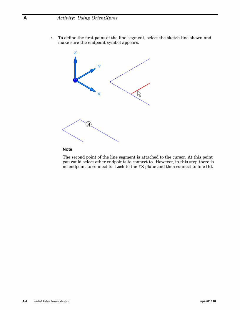
▸ To define the first point of the line segment, select the sketch line shown andmake sure the endpoint symbol appears.
Note
The second point of the line segment is attached to the cursor. At this pointyou could select other endpoints to connect to. However, in this step there isno endpoint to connect to. Lock to the YZ plane and then connect to line (B).
A-4 Solid Edge frame design spse01610

Activity: Using OrientXpres
▸ Drag the cursor over the OrientXpres triad and click when the YZ planehighlights.
The second point is now locked to the YZ plane.
▸ Select line (B) and then right-click.
The line segment (A) definition is complete.
spse01610 Solid Edge frame design A-5
A Activity: Using OrientXpres
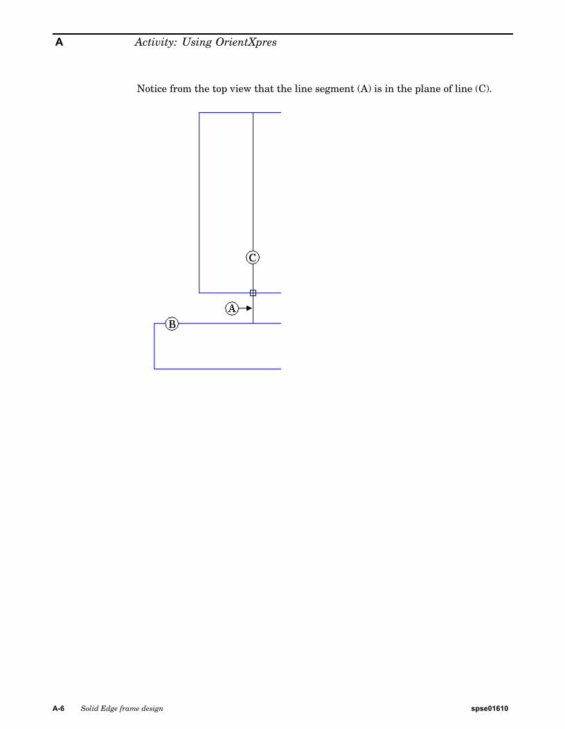
Notice from the top view that the line segment (A) is in the plane of line (C).
A-6 Solid Edge frame design spse01610
Activity: Using OrientXpres
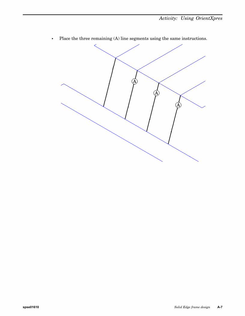
▸ Place the three remaining (A) line segments using the same instructions.
spse01610 Solid Edge frame design A-7
A Activity: Using OrientXpres
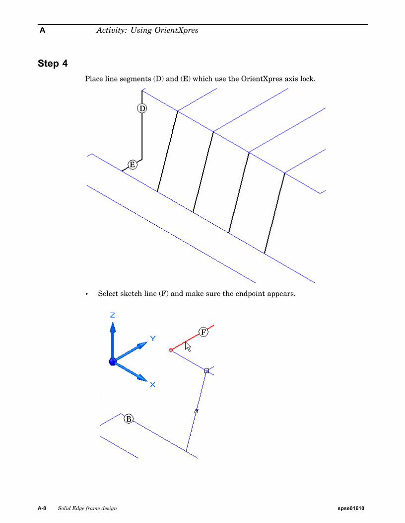
Step 4Place line segments (D) and (E) which use the OrientXpres axis lock.
▸ Select sketch line (F) and make sure the endpoint appears.
A-8 Solid Edge frame design spse01610
Activity: Using OrientXpres
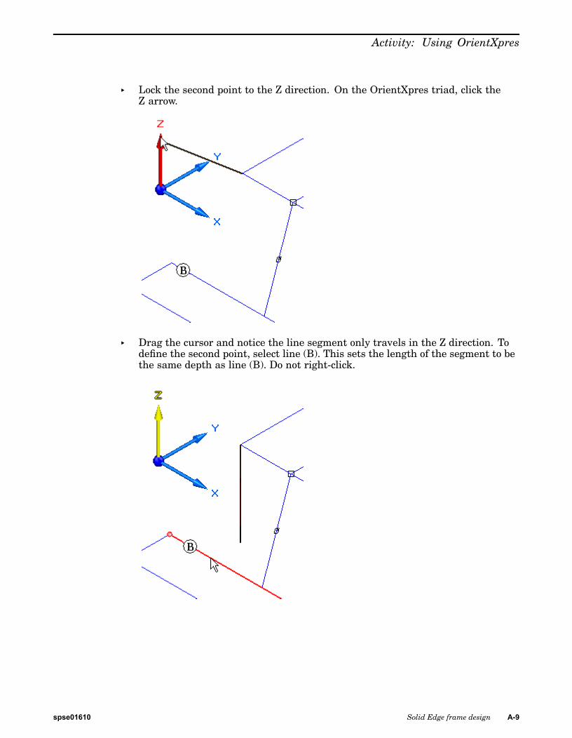
▸ Lock the second point to the Z direction. On the OrientXpres triad, click theZ arrow.
▸ Drag the cursor and notice the line segment only travels in the Z direction. Todefine the second point, select line (B). This sets the length of the segment to bethe same depth as line (B). Do not right-click.
spse01610 Solid Edge frame design A-9
A Activity: Using OrientXpres
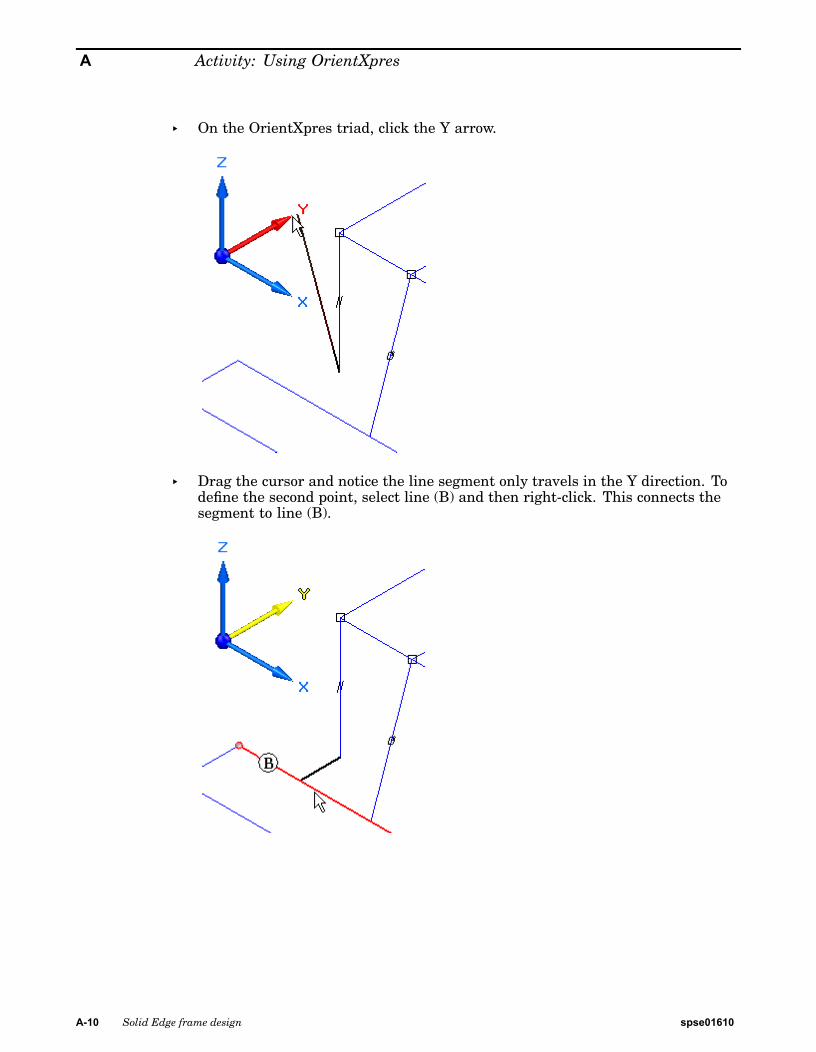
▸ On the OrientXpres triad, click the Y arrow.
▸ Drag the cursor and notice the line segment only travels in the Y direction. Todefine the second point, select line (B) and then right-click. This connects thesegment to line (B).
A-10 Solid Edge frame design spse01610
Activity: Using OrientXpres
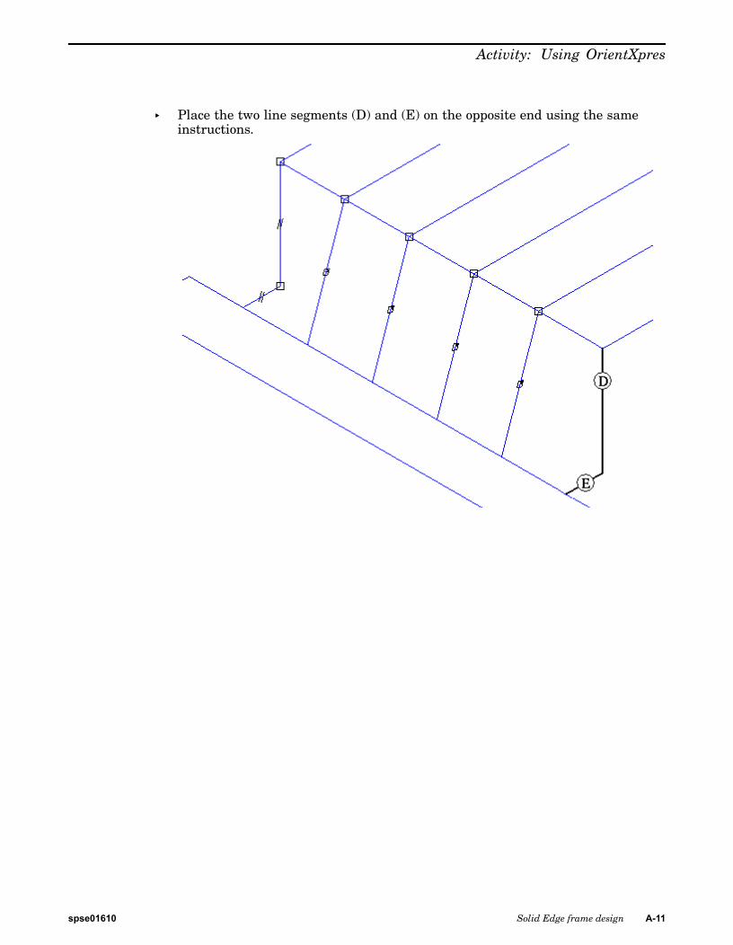
▸ Place the two line segments (D) and (E) on the opposite end using the sameinstructions.
spse01610 Solid Edge frame design A-11
A Activity: Using OrientXpres
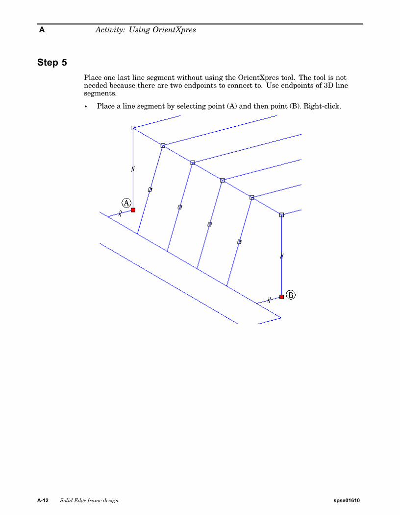
Step 5Place one last line segment without using the OrientXpres tool. The tool is notneeded because there are two endpoints to connect to. Use endpoints of 3D linesegments.
▸ Place a line segment by selecting point (A) and then point (B). Right-click.
A-12 Solid Edge frame design spse01610
Activity: Using OrientXpres
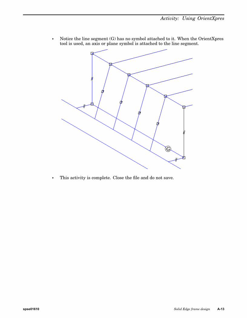
▸ Notice the line segment (G) has no symbol attached to it. When the OrientXprestool is used, an axis or plane symbol is attached to the line segment.
▸ This activity is complete. Close the file and do not save.
spse01610 Solid Edge frame design A-13

A Activity: Using OrientXpres
SummaryIn this activity you learned how to use OrientXpres to draw 3D line segments. Usethe OrientXpres triad to control the direction of a line segment.
A-14 Solid Edge frame design spse01610
B Activity: Corner treatmentoptions
Step 1
▸ Copy C-channel35.par, C-channel65.par, C-channel95.par, square30.par,square45.par, square60.par and square90.par to the Program Files/Solid EdgeST4/Frames folder.
Note
This step makes these components available when selecting the Frame–SelectCross Section Component button.
spse01610 Solid Edge frame design B-1

B Activity: Corner treatment options
Step 2▸ Open corner_options.asm.
B-2 Solid Edge frame design spse01610

Activity: Corner treatment options
Step 3▸ Start the Frame Design application.
spse01610 Solid Edge frame design B-3
B Activity: Corner treatment options
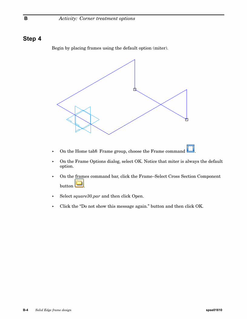
Step 4Begin by placing frames using the default option (miter).
▸ On the Home tab®Frame group, choose the Frame command .
▸ On the Frame Options dialog, select OK. Notice that miter is always the defaultoption.
▸ On the frames command bar, click the Frame–Select Cross Section Component
button .
▸ Select square30.par and then click Open.
▸ Click the “Do not show this message again.” button and then click OK.
B-4 Solid Edge frame design spse01610
Activity: Corner treatment options
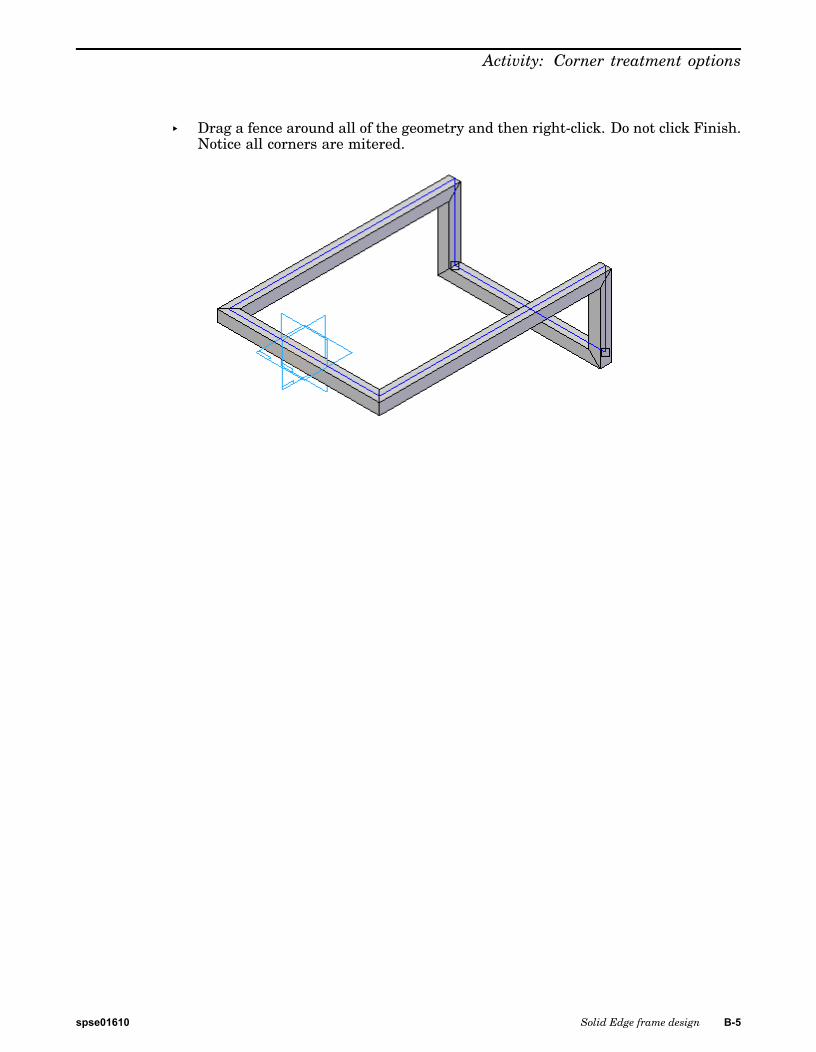
▸ Drag a fence around all of the geometry and then right-click. Do not click Finish.Notice all corners are mitered.
spse01610 Solid Edge frame design B-5
B Activity: Corner treatment options
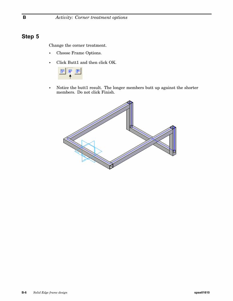
Step 5Change the corner treatment.
▸ Choose Frame Options.
▸ Click Butt1 and then click OK.
▸ Notice the butt1 result. The longer members butt up against the shortermembers. Do not click Finish.
B-6 Solid Edge frame design spse01610
Activity: Corner treatment options
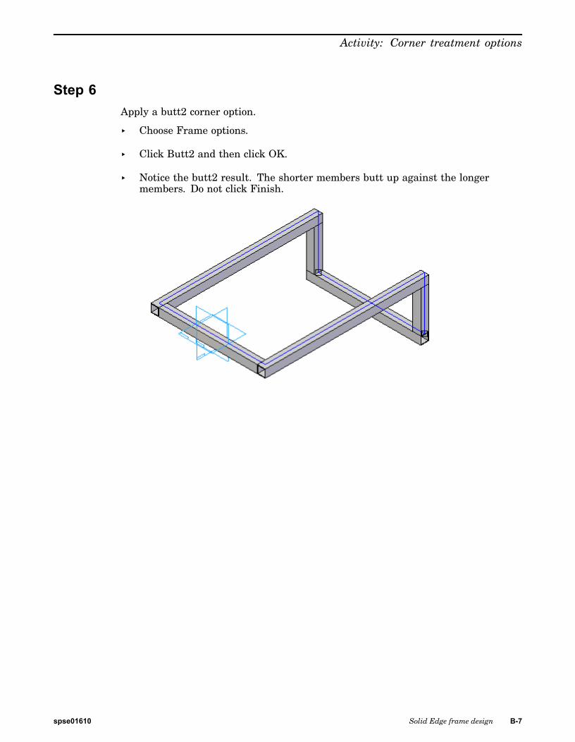
Step 6Apply a butt2 corner option.
▸ Choose Frame options.
▸ Click Butt2 and then click OK.
▸ Notice the butt2 result. The shorter members butt up against the longermembers. Do not click Finish.
spse01610 Solid Edge frame design B-7

B Activity: Corner treatment options
Step 7Apply an Extend frame component corner option.
▸ Choose Frame options.
▸ Click the Extend frame component option.
▸ Enter 80 in distance field and click OK. Notice the extend result. A negativevalue shortens the members. Do not click Finish.
B-8 Solid Edge frame design spse01610
Activity: Corner treatment options
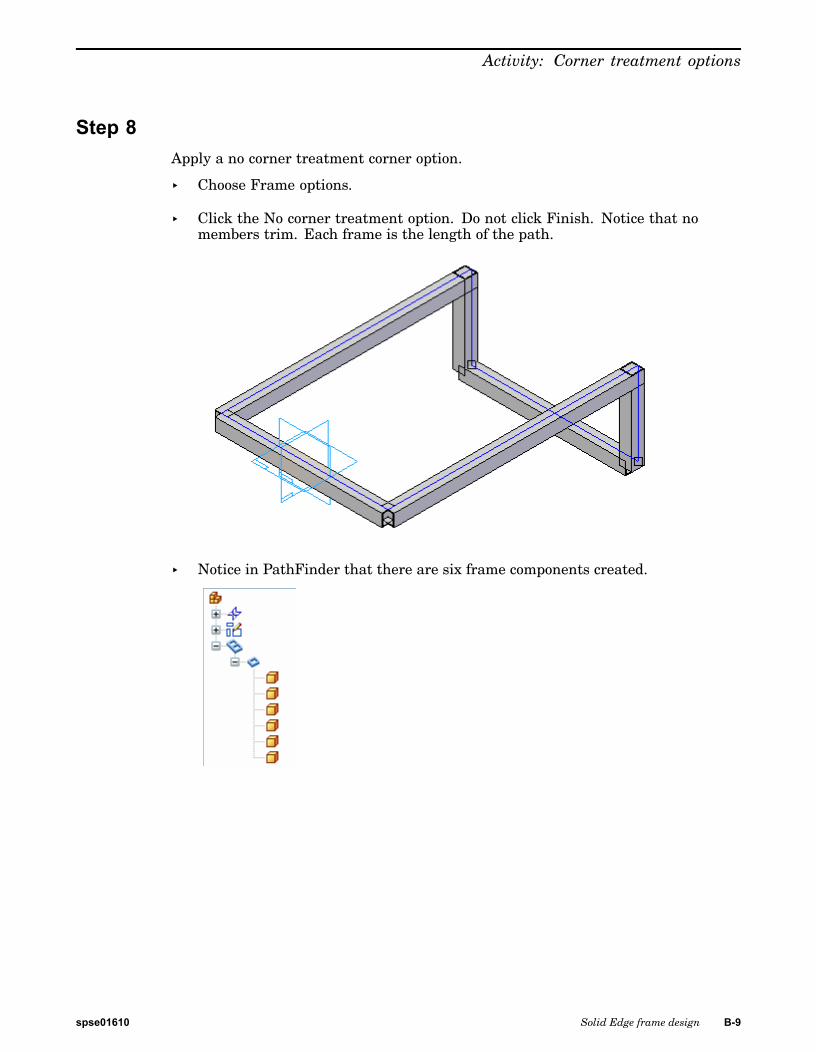
Step 8Apply a no corner treatment corner option.
▸ Choose Frame options.
▸ Click the No corner treatment option. Do not click Finish. Notice that nomembers trim. Each frame is the length of the path.
▸ Notice in PathFinder that there are six frame components created.
spse01610 Solid Edge frame design B-9
B Activity: Corner treatment options
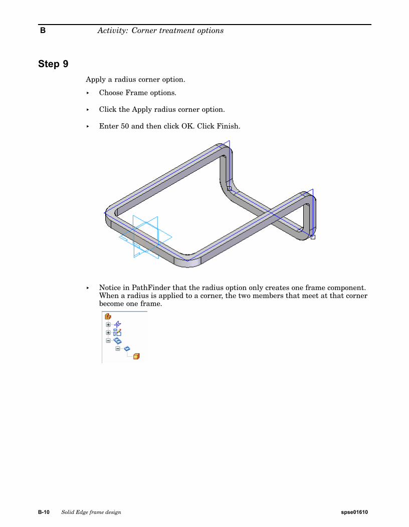
Step 9Apply a radius corner option.
▸ Choose Frame options.
▸ Click the Apply radius corner option.
▸ Enter 50 and then click OK. Click Finish.
▸ Notice in PathFinder that the radius option only creates one frame component.When a radius is applied to a corner, the two members that meet at that cornerbecome one frame.
B-10 Solid Edge frame design spse01610
Activity: Corner treatment options
Step 10This completes the activity.
Exit the assembly file and do not save. Click No to save the Display Configuration.
spse01610 Solid Edge frame design B-11

B Activity: Corner treatment options
Activity summaryChange the corner treatment options at any time during the creation of framecomponents. Once the command finishes, go back and edit the frame definitionto change the corner options.
B-12 Solid Edge frame design spse01610
C Activity: Dune buggy frame
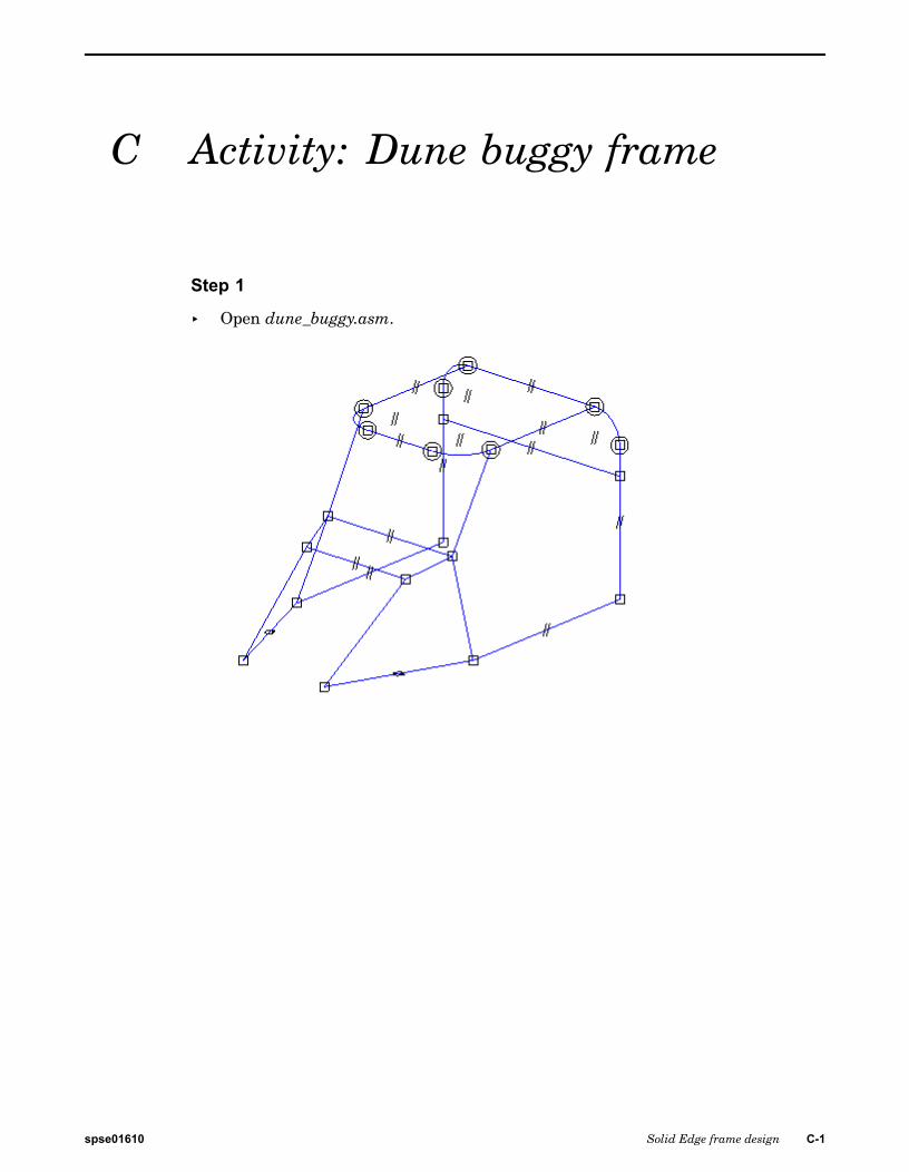
Step 1
▸ Open dune_buggy.asm.
spse01610 Solid Edge frame design C-1
C Activity: Dune buggy frame
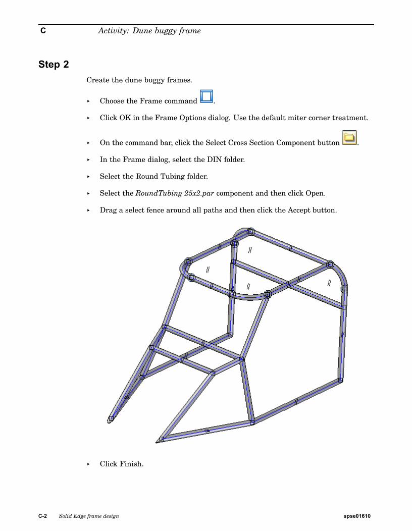
Step 2Create the dune buggy frames.
▸ Choose the Frame command .
▸ Click OK in the Frame Options dialog. Use the default miter corner treatment.
▸ On the command bar, click the Select Cross Section Component button .
▸ In the Frame dialog, select the DIN folder.
▸ Select the Round Tubing folder.
▸ Select the RoundTubing 25x2.par component and then click Open.
▸ Drag a select fence around all paths and then click the Accept button.
▸ Click Finish.
C-2 Solid Edge frame design spse01610
Activity: Dune buggy frame
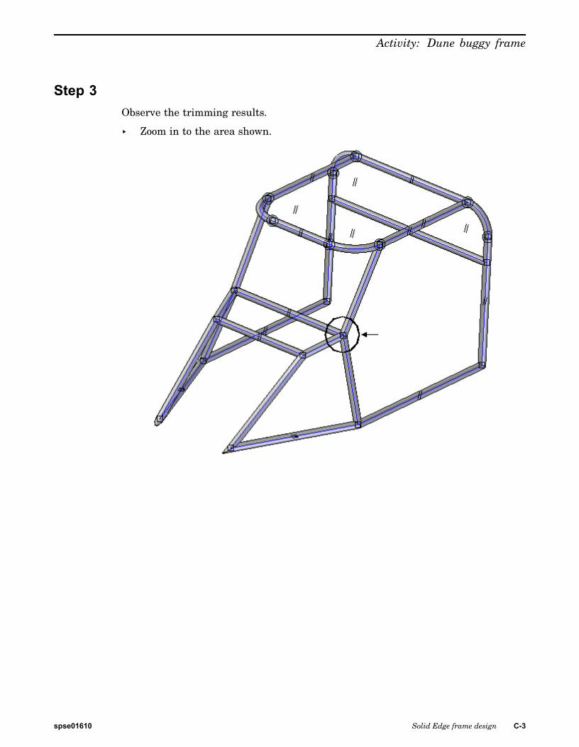
Step 3Observe the trimming results.
▸ Zoom in to the area shown.
spse01610 Solid Edge frame design C-3
C Activity: Dune buggy frame
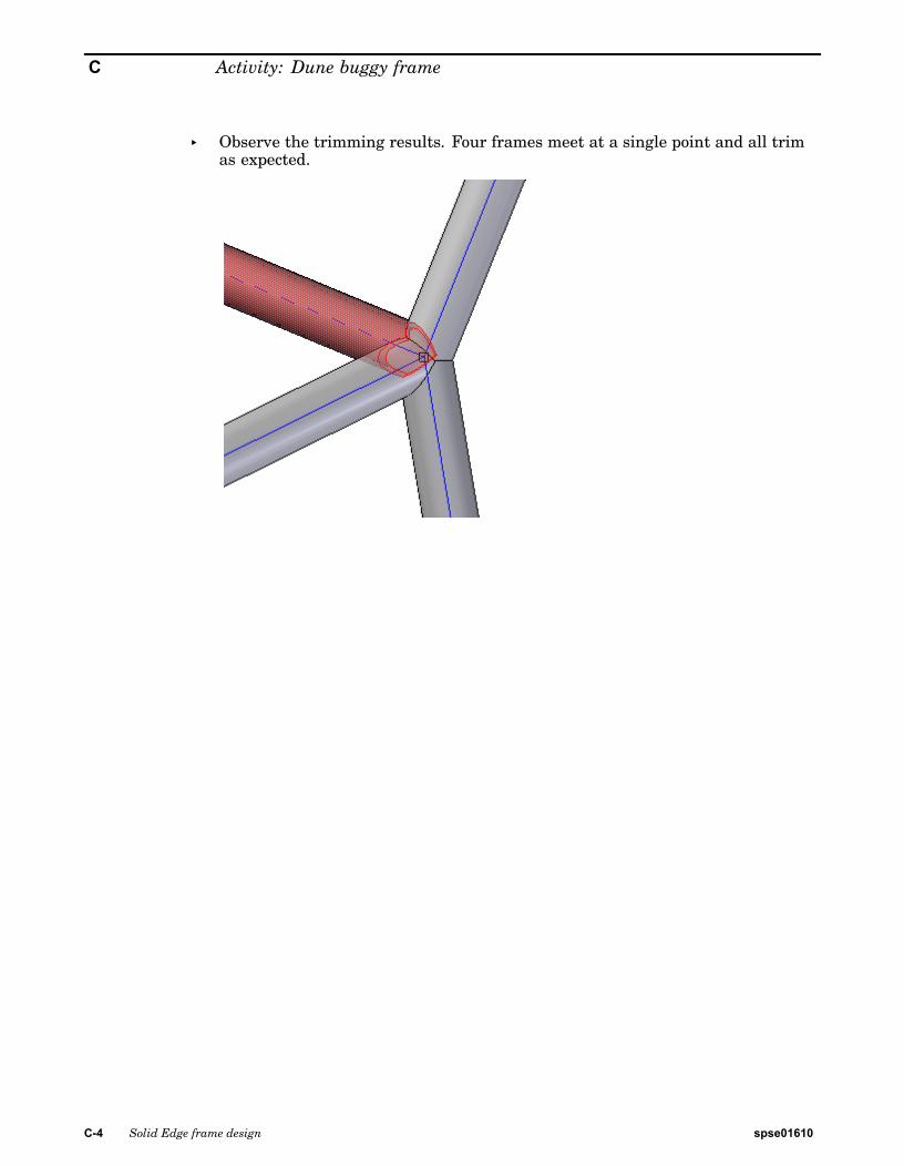
▸ Observe the trimming results. Four frames meet at a single point and all trimas expected.
C-4 Solid Edge frame design spse01610

Activity: Dune buggy frame
Step 4This completes the activity.
▸ Close dune_buggy.asm.
spse01610 Solid Edge frame design C-5


D Activity: Automatic framepositioning
Step 1
▸ Open auto-position.asm.
spse01610 Solid Edge frame design D-1
D Activity: Automatic frame positioning
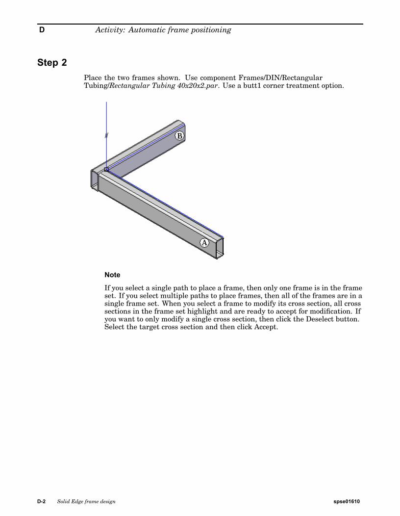
Step 2Place the two frames shown. Use component Frames/DIN/RectangularTubing/Rectangular Tubing 40x20x2.par. Use a butt1 corner treatment option.
Note
If you select a single path to place a frame, then only one frame is in the frameset. If you select multiple paths to place frames, then all of the frames are in asingle frame set. When you select a frame to modify its cross section, all crosssections in the frame set highlight and are ready to accept for modification. Ifyou want to only modify a single cross section, then click the Deselect button.Select the target cross section and then click Accept.
D-2 Solid Edge frame design spse01610
Activity: Automatic frame positioning
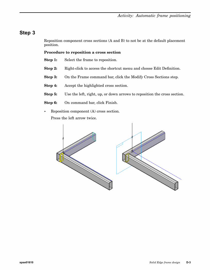
Step 3Reposition component cross sections (A and B) to not be at the default placementposition.
Procedure to reposition a cross section
Step 1: Select the frame to reposition.
Step 2: Right-click to access the shortcut menu and choose Edit Definition.
Step 3: On the Frame command bar, click the Modify Cross Sections step.
Step 4: Accept the highlighted cross section.
Step 5: Use the left, right, up, or down arrows to reposition the cross section.
Step 6: On command bar, click Finish.
▸ Reposition component (A) cross section.
Press the left arrow twice.
spse01610 Solid Edge frame design D-3
D Activity: Automatic frame positioning
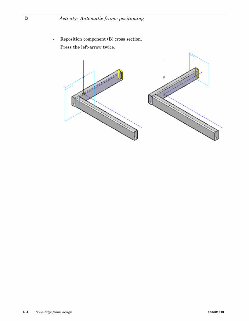
▸ Reposition component (B) cross section.
Press the left-arrow twice.
D-4 Solid Edge frame design spse01610
Activity: Automatic frame positioning
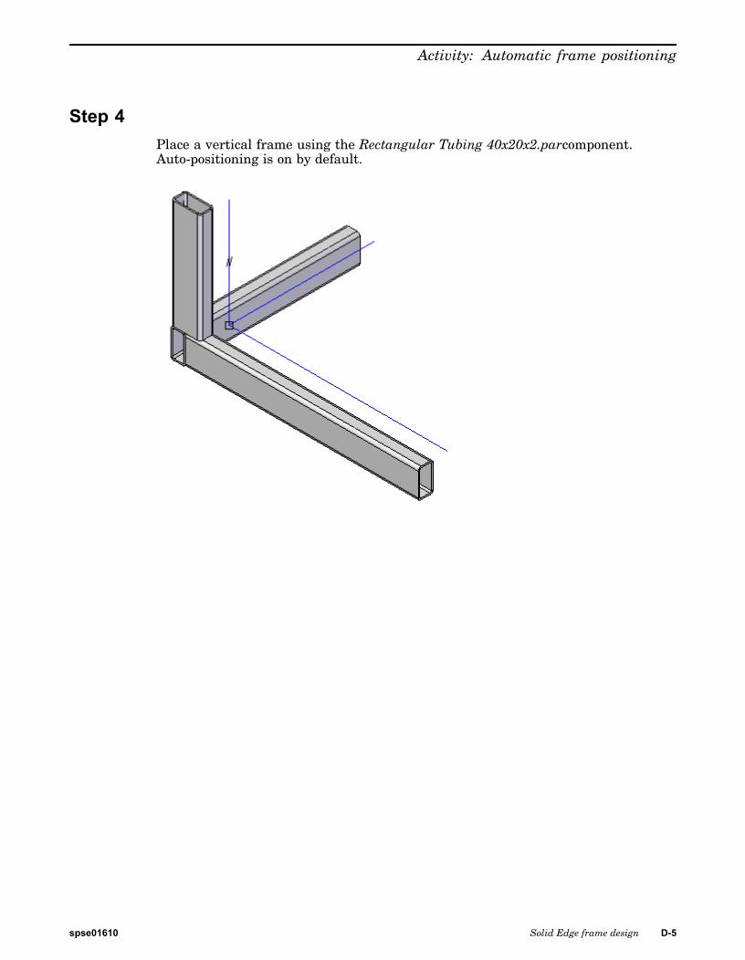
Step 4Place a vertical frame using the Rectangular Tubing 40x20x2.parcomponent.Auto-positioning is on by default.
spse01610 Solid Edge frame design D-5

D Activity: Automatic frame positioning
Step 5Edit the position of frames (A) and (B) and observe how frame (C) repositionsautomatically.
▸ Reposition component (A) cross section. Move cross section to the left and rightand notice how (C) repositions automatically.
▸ Reposition component (B) cross section. Move cross section to the left and rightand notice how (C) repositions automatically.
D-6 Solid Edge frame design spse01610
Activity: Automatic frame positioning
Step 6Turn off auto-positioning on frame (C) and notice the behavior.
▸ Edit frame (C) and turn off auto-positioning.
▸ Edit the position of frame cross sections (A and B). Notice that frame (C) remainsfixed at its last repositioned location.
spse01610 Solid Edge frame design D-7
D Activity: Automatic frame positioning
Step 7This completes the activity.
▸ Close auto-position.asm.
D-8 Solid Edge frame design spse01610
E Activity: Editing a cornertreatment
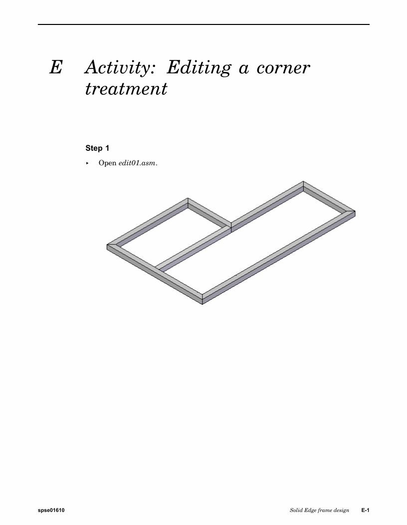
Step 1
▸ Open edit01.asm.
spse01610 Solid Edge frame design E-1
E Activity: Editing a corner treatment
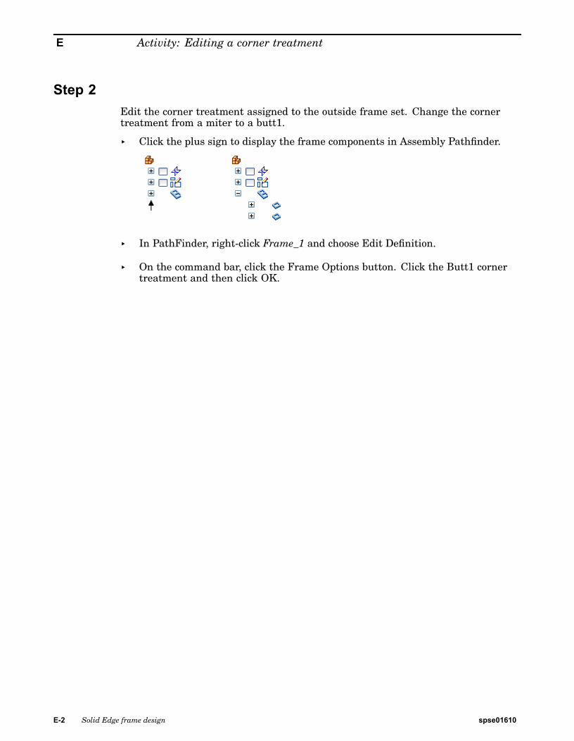
Step 2Edit the corner treatment assigned to the outside frame set. Change the cornertreatment from a miter to a butt1.
▸ Click the plus sign to display the frame components in Assembly Pathfinder.
▸ In PathFinder, right-click Frame_1 and choose Edit Definition.
▸ On the command bar, click the Frame Options button. Click the Butt1 cornertreatment and then click OK.
E-2 Solid Edge frame design spse01610
Activity: Editing a corner treatment
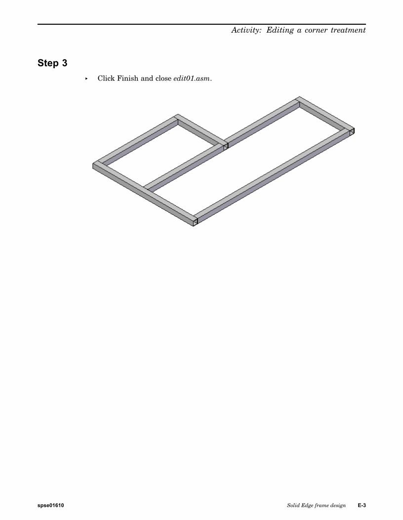
Step 3▸ Click Finish and close edit01.asm.
spse01610 Solid Edge frame design E-3

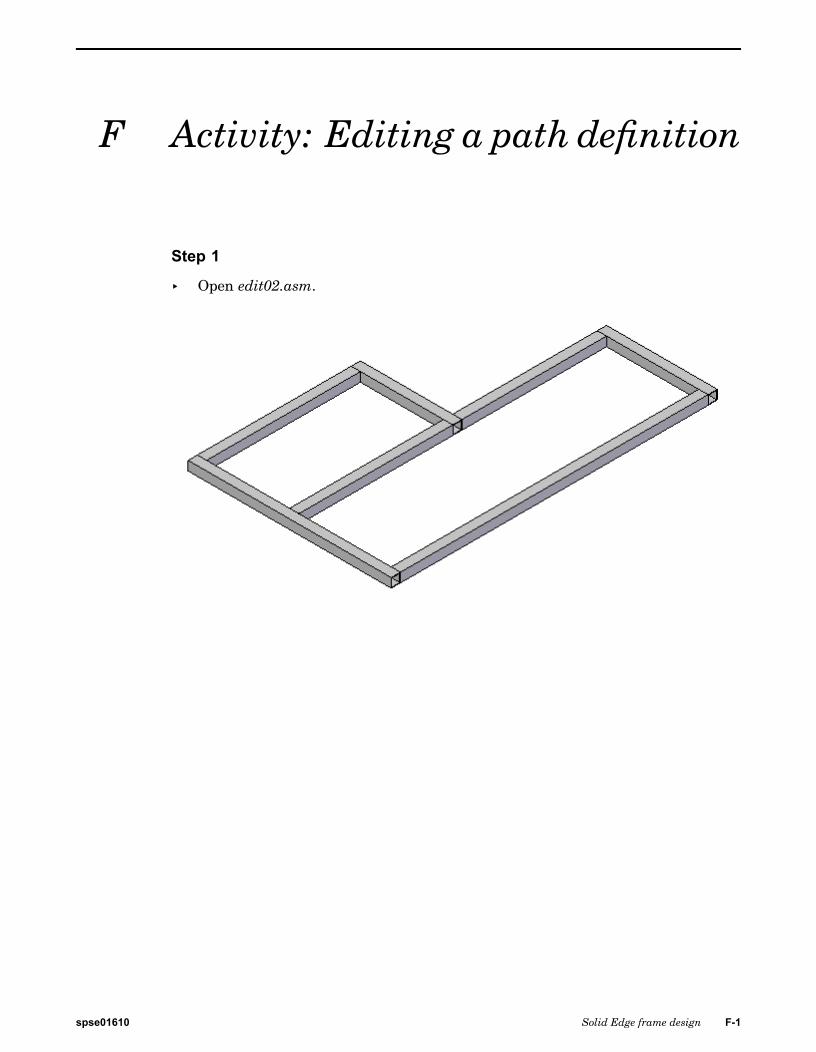
F Activity: Editing a path definition
Step 1
▸ Open edit02.asm.
spse01610 Solid Edge frame design F-1
F Activity: Editing a path definition
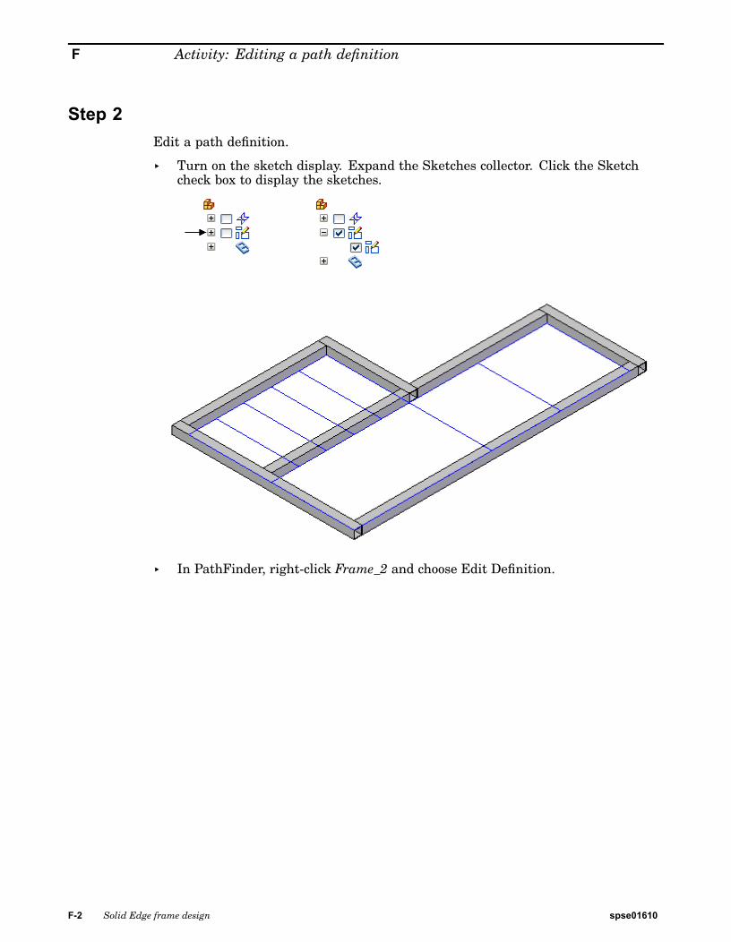
Step 2Edit a path definition.
▸ Turn on the sketch display. Expand the Sketches collector. Click the Sketchcheck box to display the sketches.
▸ In PathFinder, right-click Frame_2 and choose Edit Definition.
F-2 Solid Edge frame design spse01610
Activity: Editing a path definition
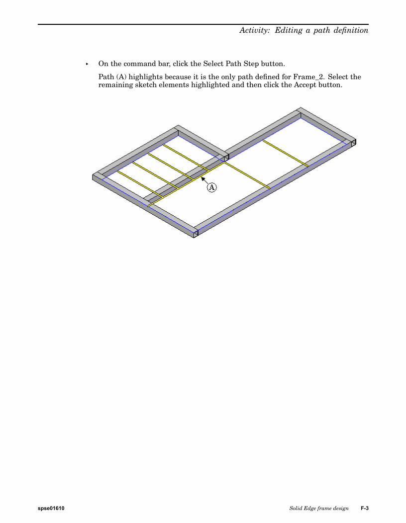
▸ On the command bar, click the Select Path Step button.
Path (A) highlights because it is the only path defined for Frame_2. Select theremaining sketch elements highlighted and then click the Accept button.
spse01610 Solid Edge frame design F-3
F Activity: Editing a path definition
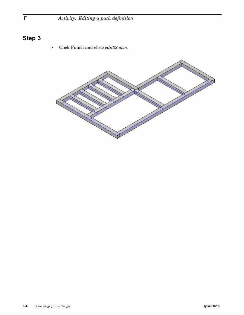
Step 3▸ Click Finish and close edit02.asm.
F-4 Solid Edge frame design spse01610
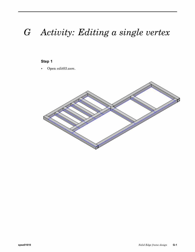
G Activity: Editing a single vertex
Step 1
▸ Open edit03.asm.
spse01610 Solid Edge frame design G-1
G Activity: Editing a single vertex
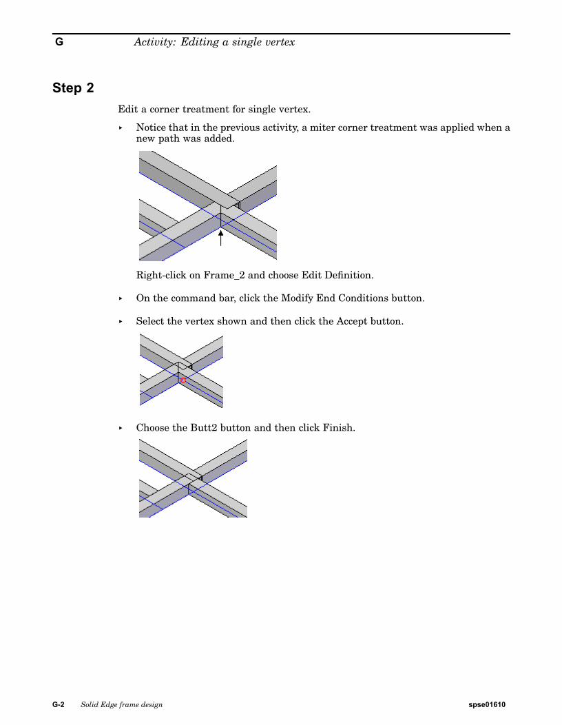
Step 2Edit a corner treatment for single vertex.
▸ Notice that in the previous activity, a miter corner treatment was applied when anew path was added.
Right-click on Frame_2 and choose Edit Definition.
▸ On the command bar, click the Modify End Conditions button.
▸ Select the vertex shown and then click the Accept button.
▸ Choose the Butt2 button and then click Finish.
G-2 Solid Edge frame design spse01610

Activity: Editing a single vertex
Step 3▸ Close edit03.asm.
spse01610 Solid Edge frame design G-3

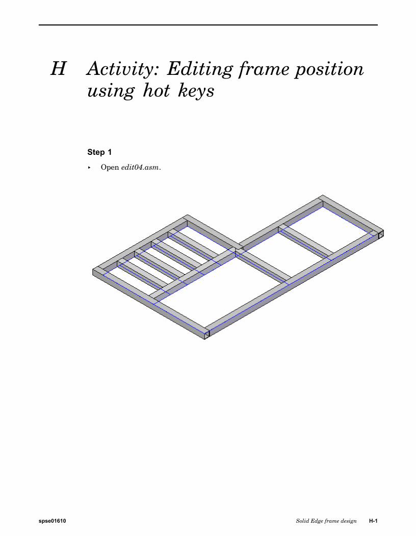
H Activity: Editing frame positionusing hot keys
Step 1
▸ Open edit04.asm.
spse01610 Solid Edge frame design H-1
H Activity: Editing frame position using hot keys
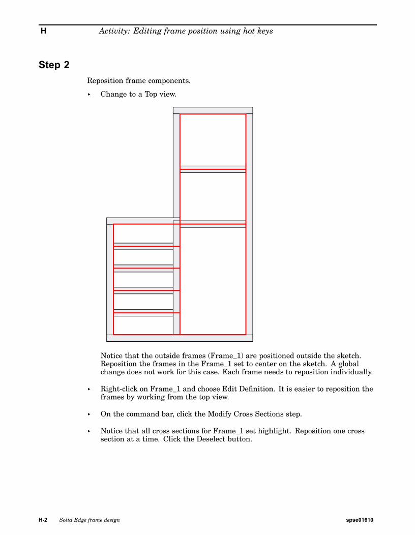
Step 2Reposition frame components.
▸ Change to a Top view.
Notice that the outside frames (Frame_1) are positioned outside the sketch.Reposition the frames in the Frame_1 set to center on the sketch. A globalchange does not work for this case. Each frame needs to reposition individually.
▸ Right-click on Frame_1 and choose Edit Definition. It is easier to reposition theframes by working from the top view.
▸ On the command bar, click the Modify Cross Sections step.
▸ Notice that all cross sections for Frame_1 set highlight. Reposition one crosssection at a time. Click the Deselect button.
H-2 Solid Edge frame design spse01610
Activity: Editing frame position using hot keys
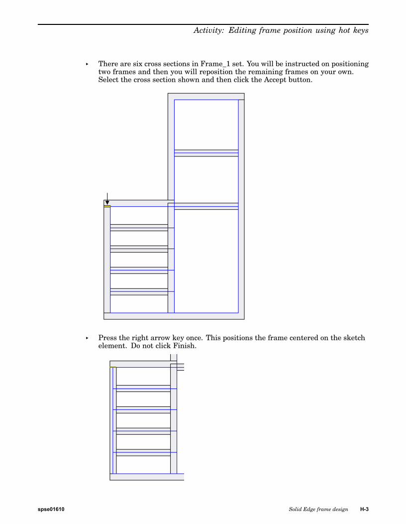
▸ There are six cross sections in Frame_1 set. You will be instructed on positioningtwo frames and then you will reposition the remaining frames on your own.Select the cross section shown and then click the Accept button.
▸ Press the right arrow key once. This positions the frame centered on the sketchelement. Do not click Finish.
spse01610 Solid Edge frame design H-3
H Activity: Editing frame position using hot keys
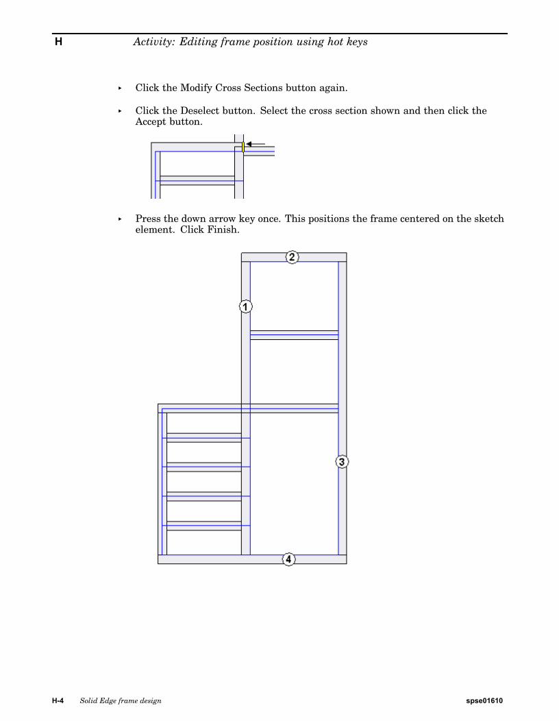
▸ Click the Modify Cross Sections button again.
▸ Click the Deselect button. Select the cross section shown and then click theAccept button.
▸ Press the down arrow key once. This positions the frame centered on the sketchelement. Click Finish.
H-4 Solid Edge frame design spse01610
Activity: Editing frame position using hot keys
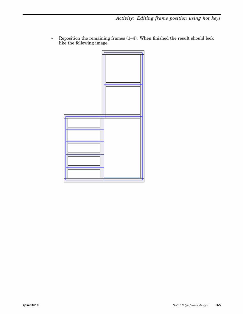
▸ Reposition the remaining frames (1–4). When finished the result should looklike the following image.
spse01610 Solid Edge frame design H-5
H Activity: Editing frame position using hot keys
Step 3▸ Close edit_04.par.
H-6 Solid Edge frame design spse01610
I Activity: Editing frame positionusing snap points
Step 1
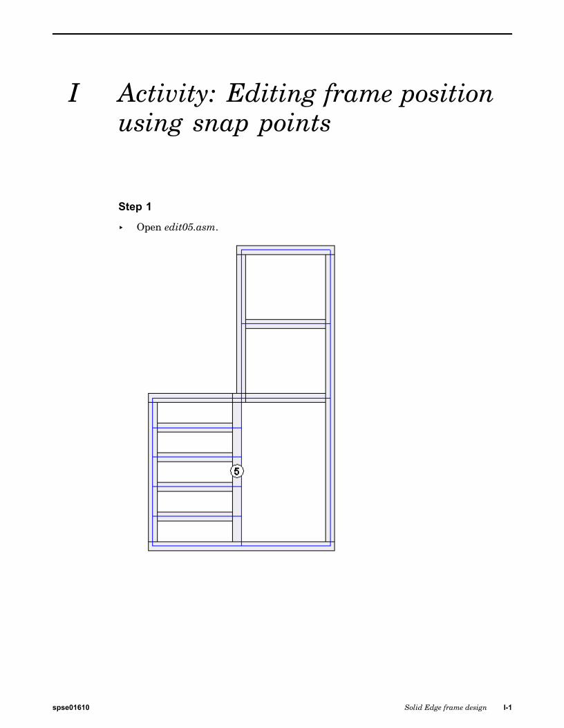
▸ Open edit05.asm.
spse01610 Solid Edge frame design I-1
I Activity: Editing frame position using snap points
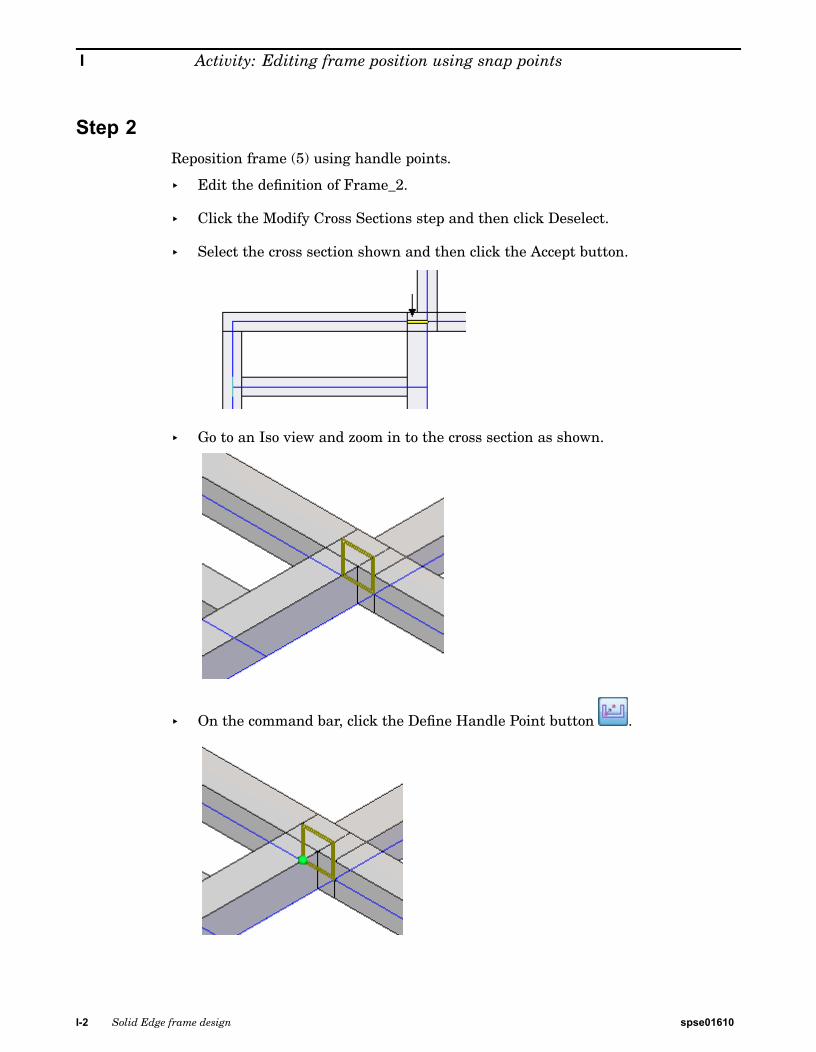
Step 2Reposition frame (5) using handle points.
▸ Edit the definition of Frame_2.
▸ Click the Modify Cross Sections step and then click Deselect.
▸ Select the cross section shown and then click the Accept button.
▸ Go to an Iso view and zoom in to the cross section as shown.
▸ On the command bar, click the Define Handle Point button .
I-2 Solid Edge frame design spse01610
Activity: Editing frame position using snap points
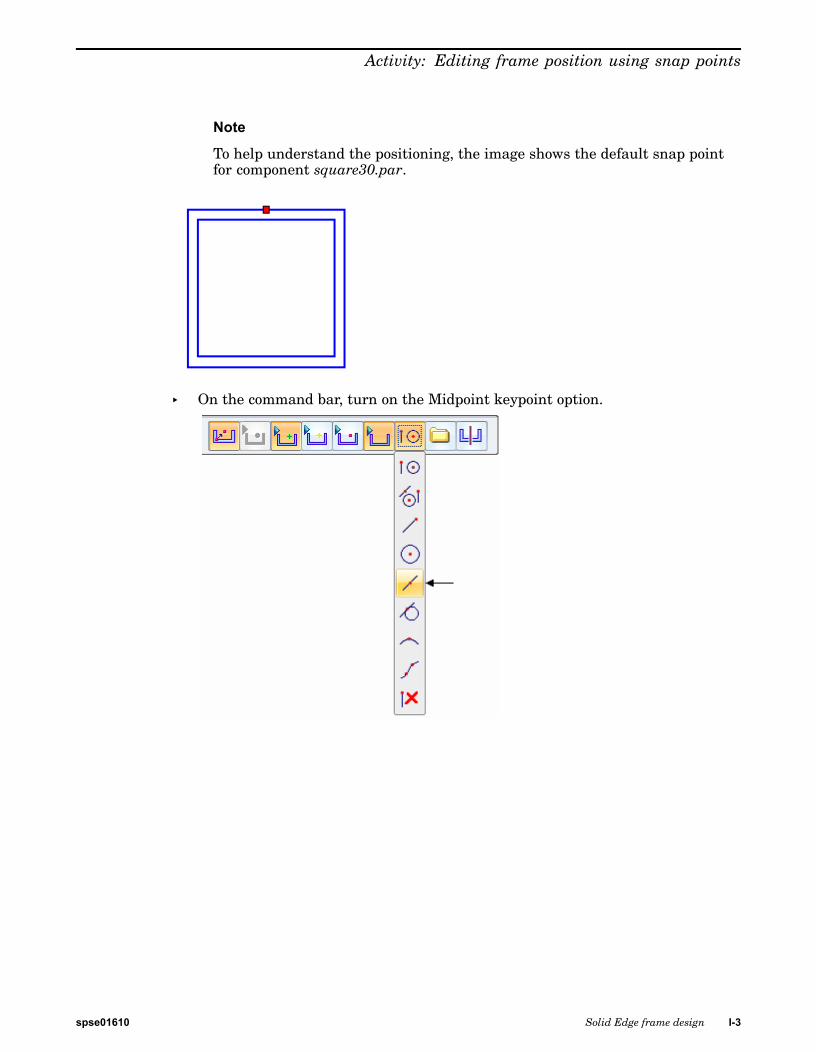
Note
To help understand the positioning, the image shows the default snap pointfor component square30.par.
▸ On the command bar, turn on the Midpoint keypoint option.
spse01610 Solid Edge frame design I-3
I Activity: Editing frame position using snap points
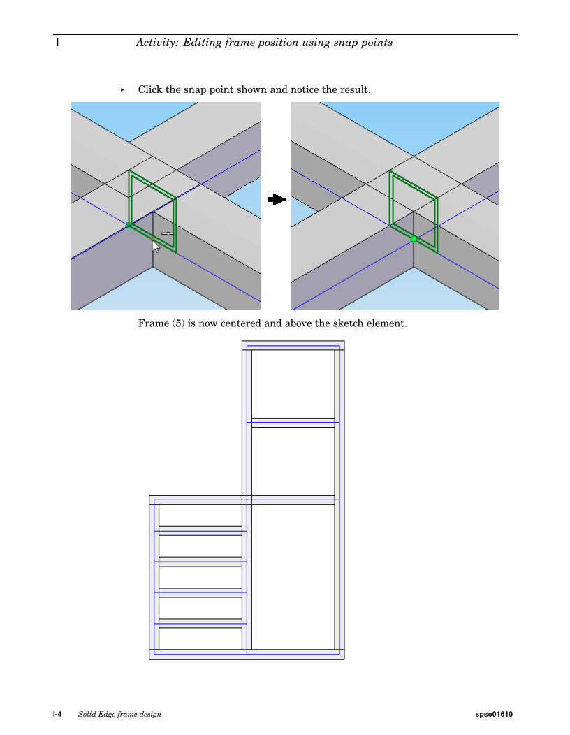
▸ Click the snap point shown and notice the result.
Frame (5) is now centered and above the sketch element.
I-4 Solid Edge frame design spse01610
Activity: Editing frame position using snap points
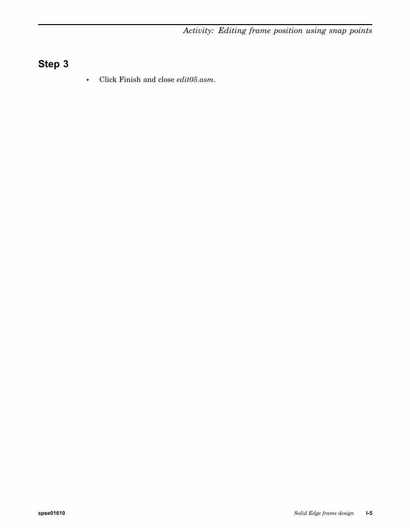
Step 3▸ Click Finish and close edit05.asm.
spse01610 Solid Edge frame design I-5


J Activity: Editing framecomponents
Step 1
▸ Open edit06.asm.
spse01610 Solid Edge frame design J-1
J Activity: Editing frame components
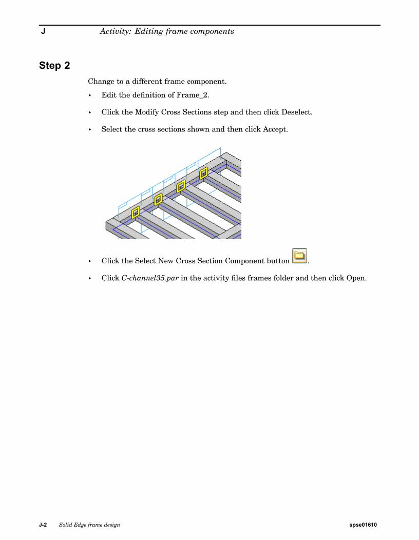
Step 2Change to a different frame component.
▸ Edit the definition of Frame_2.
▸ Click the Modify Cross Sections step and then click Deselect.
▸ Select the cross sections shown and then click Accept.
▸ Click the Select New Cross Section Component button .
▸ Click C-channel35.par in the activity files frames folder and then click Open.
J-2 Solid Edge frame design spse01610
Activity: Editing frame components
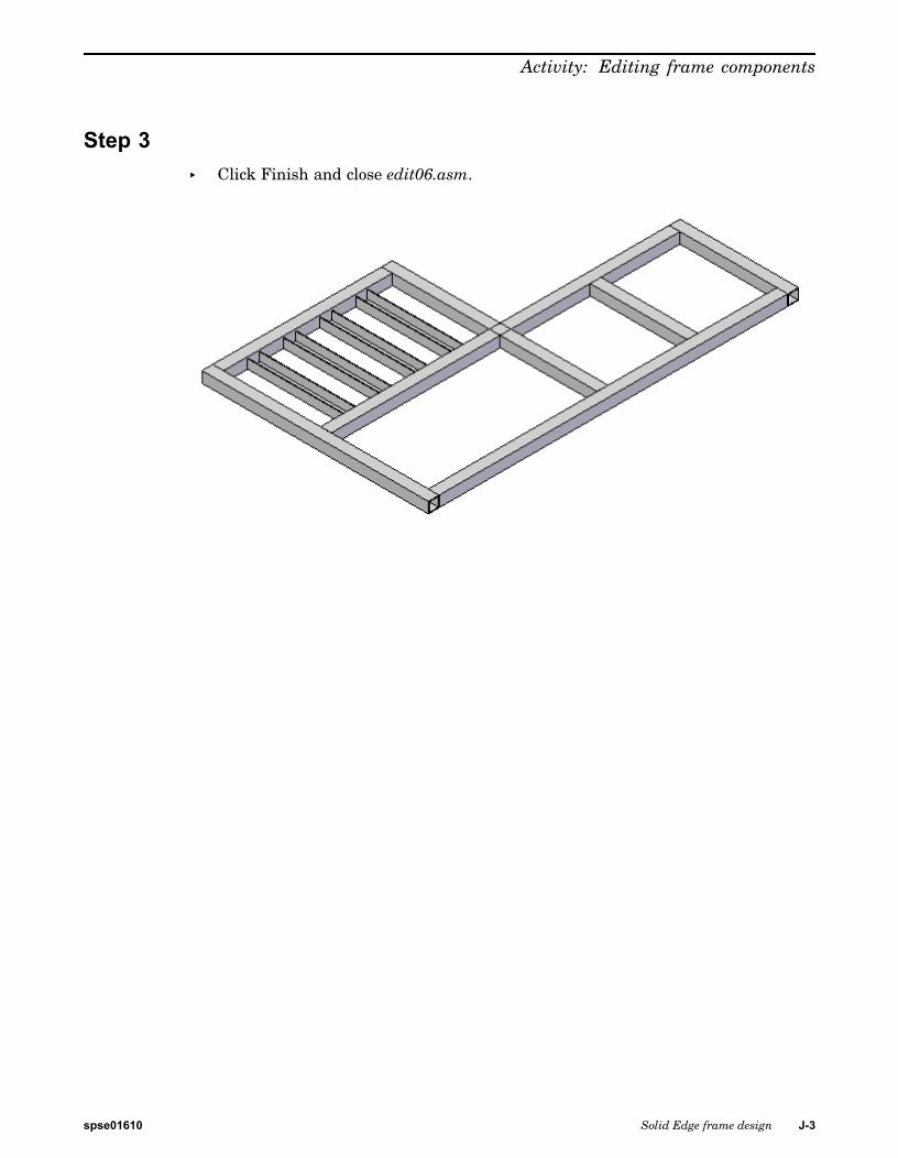
Step 3▸ Click Finish and close edit06.asm.
spse01610 Solid Edge frame design J-3

K Activity: Editing frame crosssection orientation
Step 1
▸ Open edit07.asm. The last edit is a change to the cross section orientation.
spse01610 Solid Edge frame design K-1
K Activity: Editing frame cross section orientation
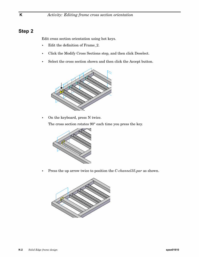
Step 2Edit cross section orientation using hot keys.
▸ Edit the definition of Frame_2.
▸ Click the Modify Cross Sections step, and then click Deselect.
▸ Select the cross section shown and then click the Accept button.
▸ On the keyboard, press N twice.
The cross section rotates 90° each time you press the key.
▸ Press the up arrow twice to position the C-channel35.par as shown.
K-2 Solid Edge frame design spse01610
Activity: Editing frame cross section orientation
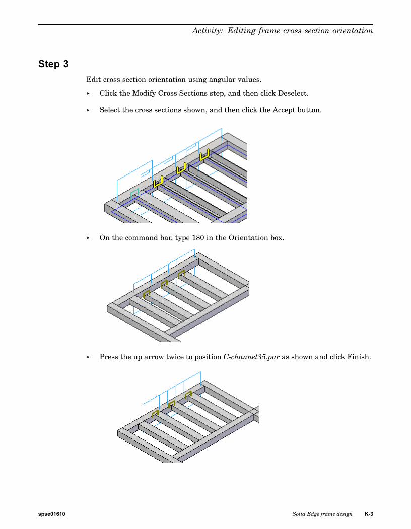
Step 3Edit cross section orientation using angular values.
▸ Click the Modify Cross Sections step, and then click Deselect.
▸ Select the cross sections shown, and then click the Accept button.
▸ On the command bar, type 180 in the Orientation box.
▸ Press the up arrow twice to position C-channel35.par as shown and click Finish.
spse01610 Solid Edge frame design K-3
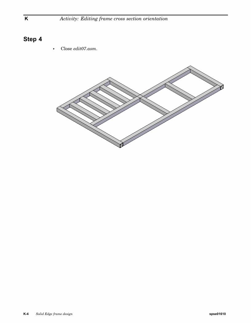
K Activity: Editing frame cross section orientation
Step 4▸ Close edit07.asm.
K-4 Solid Edge frame design spse01610

L Activity: Coping joints andcollinear paths
Step 1
▸ Open coping.asm.
spse01610 Solid Edge frame design L-1

L Activity: Coping joints and collinear paths
Step 2Place frames on the outside paths and also on path (A), which spans across the center.
▸ Choose the Frame command .
▸ Select the Butt1 corner treatment option.
▸ On the Frame command bar, click the Select Cross Section Component button
.
▸ In the Frames/DIN/I-Beam folder, select I-Beam 80x46.par and click Open.
▸ Select the four outside lines and line (A). Right-click.
L-2 Solid Edge frame design spse01610
Activity: Coping joints and collinear paths
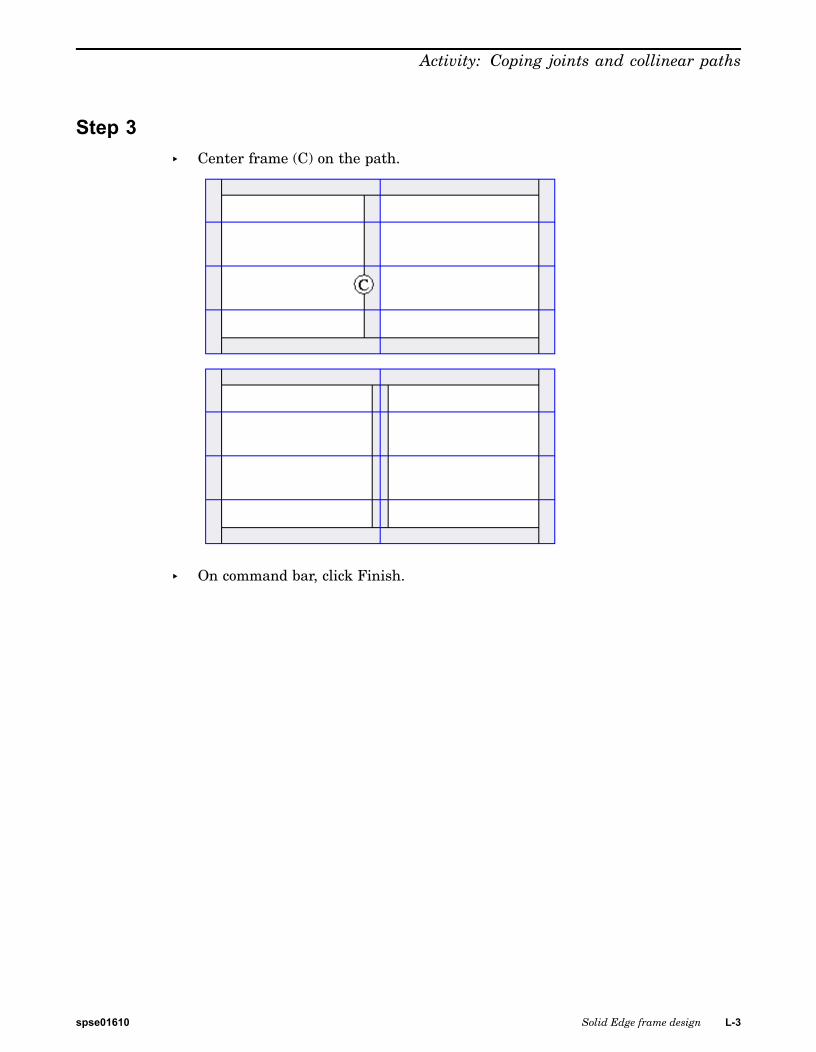
Step 3▸ Center frame (C) on the path.
▸ On command bar, click Finish.
spse01610 Solid Edge frame design L-3
L Activity: Coping joints and collinear paths
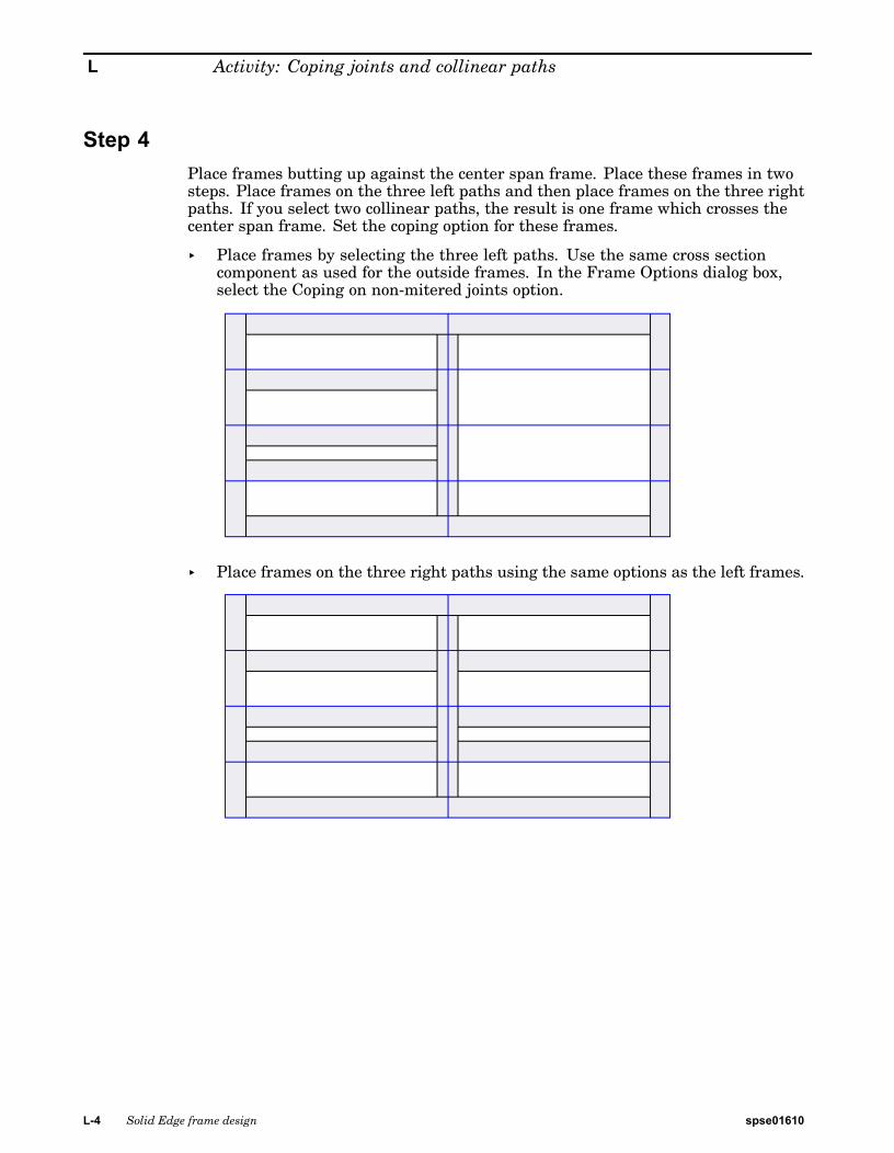
Step 4Place frames butting up against the center span frame. Place these frames in twosteps. Place frames on the three left paths and then place frames on the three rightpaths. If you select two collinear paths, the result is one frame which crosses thecenter span frame. Set the coping option for these frames.
▸ Place frames by selecting the three left paths. Use the same cross sectioncomponent as used for the outside frames. In the Frame Options dialog box,select the Coping on non-mitered joints option.
▸ Place frames on the three right paths using the same options as the left frames.
L-4 Solid Edge frame design spse01610

Activity: Coping joints and collinear paths
Step 5▸ Center the six frames, that butt up to the center span frame, on their paths.
spse01610 Solid Edge frame design L-5
L Activity: Coping joints and collinear paths
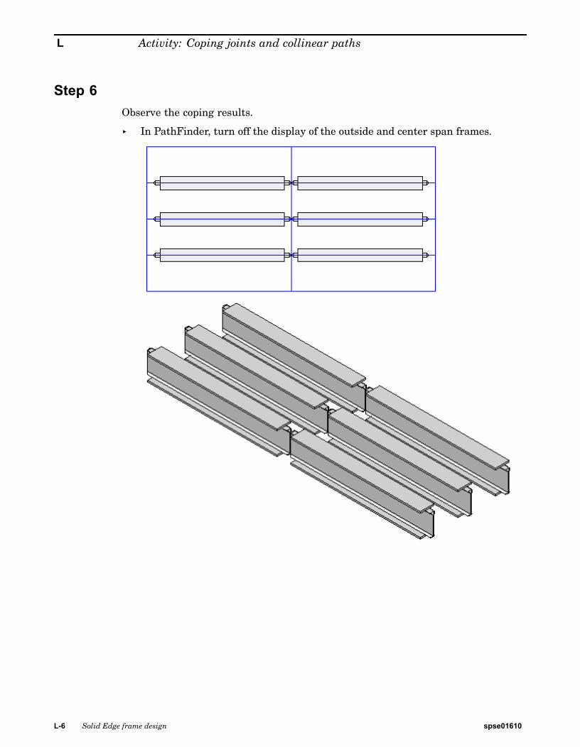
Step 6Observe the coping results.
▸ In PathFinder, turn off the display of the outside and center span frames.
L-6 Solid Edge frame design spse01610

Activity: Coping joints and collinear paths
Step 7▸ This completes the activity. Close the file.
spse01610 Solid Edge frame design L-7

M Activity: Creating a custom frame
Create a custom frame
Note
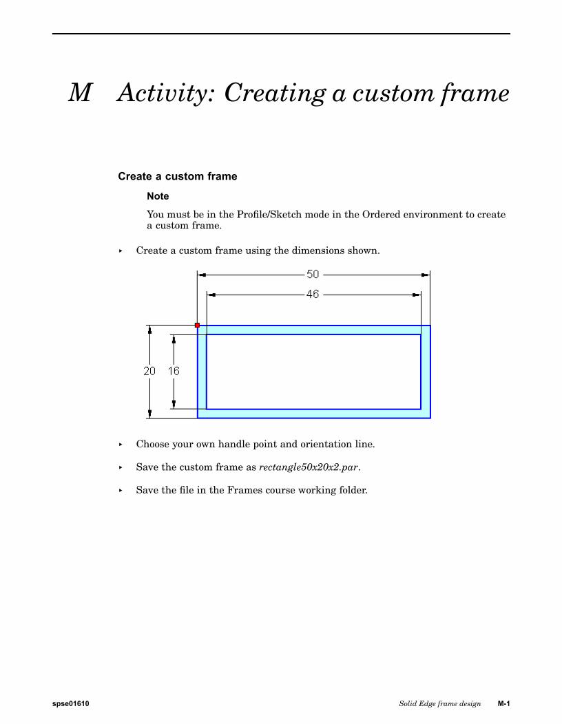
You must be in the Profile/Sketch mode in the Ordered environment to createa custom frame.
▸ Create a custom frame using the dimensions shown.
▸ Choose your own handle point and orientation line.
▸ Save the custom frame as rectangle50x20x2.par.
▸ Save the file in the Frames course working folder.
spse01610 Solid Edge frame design M-1

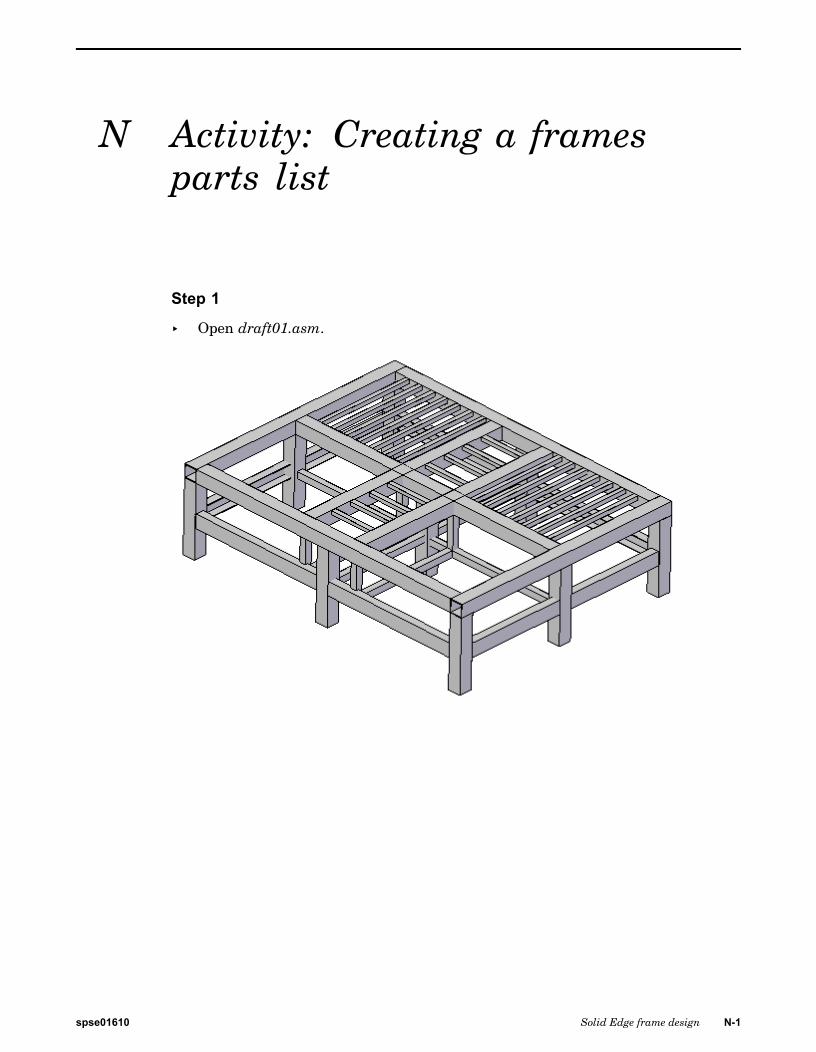
N Activity: Creating a framesparts list
Step 1
▸ Open draft01.asm.
spse01610 Solid Edge frame design N-1

N Activity: Creating a frames parts list
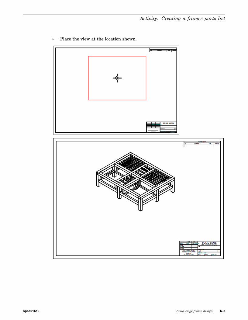
Step 2Create a drawing of the frame assembly.
▸ Choose Application button®New®Create Drawing.
▸ In the Create View dialog box, make sure the Run Drawing View Wizard optionis checked and then click OK.
▸ In the Drawing View Creation Wizard, select Create Draft Quality drawingviews. and then select 3 Finer display from the View quality list. Click Next.
▸ In the Named Views box, click iso, and then click Finish.
N-2 Solid Edge frame design spse01610
Activity: Creating a frames parts list
▸ Place the view at the location shown.
spse01610 Solid Edge frame design N-3

N Activity: Creating a frames parts list
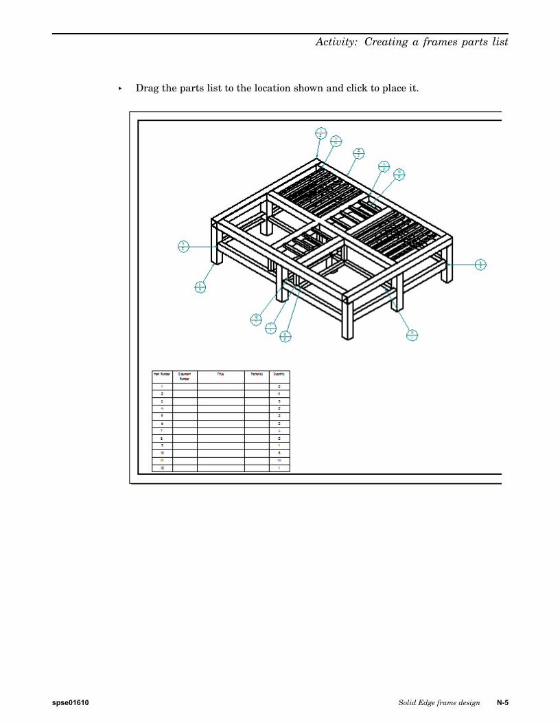
Step 3Create a parts list.
▸ On the Home tab®Tables group, choose the Parts List command .
▸ Click the drawing view.
▸ On the command bar, select the Auto-Balloon button .
N-4 Solid Edge frame design spse01610
Activity: Creating a frames parts list
▸ Drag the parts list to the location shown and click to place it.
spse01610 Solid Edge frame design N-5
N Activity: Creating a frames parts list
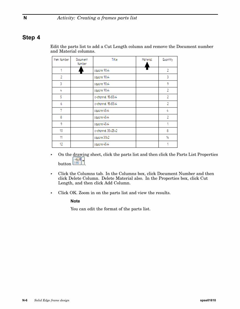
Step 4Edit the parts list to add a Cut Length column and remove the Document numberand Material columns.
▸ On the drawing sheet, click the parts list and then click the Parts List Properties
button .
▸ Click the Columns tab. In the Columns box, click Document Number and thenclick Delete Column. Delete Material also. In the Properties box, click CutLength, and then click Add Column.
▸ Click OK. Zoom in on the parts list and view the results.
Note
You can edit the format of the parts list.
N-6 Solid Edge frame design spse01610
Activity: Creating a frames parts list
Step 5Edit the parts list to show the rough cut frame lengths.
▸ In the Parts List Properties dialog box, click the Options tab. Type 10 in theFrame rough cut end clearance box.
▸ Click the Columns tab. In the Columns box, click Cut Length. Change the titlein the Text box to Rough Cut Length, and then click OK.
▸ Zoom in on the parts list to observe the changes made.
spse01610 Solid Edge frame design N-7
N Activity: Creating a frames parts list
Step 6Edit the parts list to show the total length of each component type.
▸ Click the Columns tab. In the Columns box, remove Rough Cut Length andQuantity. Select the Total Length property and add it as a column.
▸ Click the Options tab. Select the check box to Create a total length parts listand then click OK.
Observe the parts list.
N-8 Solid Edge frame design spse01610

Activity: Creating a frames parts list
Step 7▸ This completes the activity. Exit and save the draft file as draft01.dft.
spse01610 Solid Edge frame design N-9