Cable Ladder Bonding with Earth Wire, Is it Necessary?
8
TPMJH-201001 1 Abstract — In Western Australian mining sites there is a practice of bonding cable ladder sections with an earth wire, instead of relying totally on the splice plates for earthing. A common requirement today is the provision of earthing conductors linking cold formed cable ladder sections. There is a lack of information relating as to the relevance of this requirement or where this practice has originated. This paper reports on testing carried out on actual cable ladder, and examines the effect of adding an earthing conductor to achieve a continuous low resistance earth path between the cable ladder sections. From an examination of the results, assessment is made of the effectiveness of the bonding conductor, followed by discussion of the risks involved with and without earth wires, and the merits of discontinuing or continuing the practice. Index Terms — Bonding, Earth Wire, Jumper, Cable Ladder, Cable Tray, Earthing. I. INTRODUCTION OR the majority of installations, especially in process and crushing plants in mining industries, there is a large quantity of cable ladder installed, where it is used primarily for supporting electric cables. The cable ladder generally used is metal, and as such is considered a wiring enclosure which may become live, requiring grounding. Earthing of the cable ladder is important and is also a requirement of The Wiring Rules, AS 3000. Electrical grounding is essential for both personnel safety and to ensure protection systems operate correctly to remove power from a faulted cable. However the wiring standards do not stipulate that cable ladder sections be bonded by earthing wires across each joint, merely that the ladder itself be bonded to the main earthing system. There appears to be mixed opinions and engineering knowledge as to the practice of installing bonding wires, or to its relevance in the installation of cable ladder systems. This paper investigates the effectiveness of the current Manuscript received April 1, 2010. (Current version published April 1, 2010.) This work was supported in part by Kounis Metal Industries Perth WA. Paper no. TPMJH201001. Michael J Hamilton is with Elinco Engineering Services, Perth WA; PO Box 510 Balcatta WA 6914, Tel: 0418 277 177, e-mail: [email protected]. File Number: TPMJH-201001. practice of using bonding wires across joined sections of cable ladder for providing a continuous earth path, and the merit of providing earth wires as an improvement to reducing the resistance across a splice plate section of the cable ladder system. The risk will also be investigated where an earth bonding wire is not used to form part of the earthing system. II. BACKGROUND The current practice as seen from experience of many cable ladder installations is the prolific use of bonding wires. Figure 1, shows an example of such a typical installation in a mining environment that has earth bonding wires between all cable ladder sections. Figure 2 showing a close up of the cable ladder. Generally only one earth bonding wire is installed to the ladder, which is to the outside face of the ladder system as the inside rail would not easily be visible or accessible. Fig. 1. Typical photograph of installed cable ladder showing separate earth bonding cables. In an effort to find out where this practice may have developed from, questions that have been asked of electrical personnel on various sites offered no resolution. Some people, a minority, believe the earth bonding wire is not required, whereas the vast majority believe it is required. Commonly electrical supervisors on site would not approve the installation and would not allow power to be applied until all cable ladder bonding wires had been installed to all splice joints of cable ladder. Cable Ladder Bonding with Earth Wire, Is it Necessary? Michael J Hamilton, Member IEAust. F
-
Upload
mike-hamilton -
Category
Engineering
-
view
49 -
download
7
Transcript of Cable Ladder Bonding with Earth Wire, Is it Necessary?
TPMJH-201001
1
Abstract — In Western Australian mining sites there is a
practice of bonding cable ladder sections with an earth wire,
instead of relying totally on the splice plates for earthing. A
common requirement today is the provision of earthing
conductors linking cold formed cable ladder sections. There is a
lack of information relating as to the relevance of this
requirement or where this practice has originated. This paper
reports on testing carried out on actual cable ladder, and
examines the effect of adding an earthing conductor to achieve a
continuous low resistance earth path between the cable ladder
sections. From an examination of the results, assessment is made
of the effectiveness of the bonding conductor, followed by
discussion of the risks involved with and without earth wires, and
the merits of discontinuing or continuing the practice.
Index Terms — Bonding, Earth Wire, Jumper, Cable Ladder,
Cable Tray, Earthing.
I. INTRODUCTION
OR the majority of installations, especially in process and
crushing plants in mining industries, there is a large
quantity of cable ladder installed, where it is used primarily for
supporting electric cables. The cable ladder generally used is
metal, and as such is considered a wiring enclosure which may
become live, requiring grounding. Earthing of the cable ladder
is important and is also a requirement of The Wiring Rules,
AS 3000. Electrical grounding is essential for both personnel
safety and to ensure protection systems operate correctly to
remove power from a faulted cable. However the wiring
standards do not stipulate that cable ladder sections be bonded
by earthing wires across each joint, merely that the ladder
itself be bonded to the main earthing system.
There appears to be mixed opinions and engineering
knowledge as to the practice of installing bonding wires, or to
its relevance in the installation of cable ladder systems.
This paper investigates the effectiveness of the current
Manuscript received April 1, 2010. (Current version published April 1,
2010.) This work was supported in part by Kounis Metal Industries Perth
WA. Paper no. TPMJH201001.
Michael J Hamilton is with Elinco Engineering Services, Perth WA; PO
Box 510 Balcatta WA 6914, Tel: 0418 277 177, e-mail:
File Number: TPMJH-201001.
practice of using bonding wires across joined sections of cable
ladder for providing a continuous earth path, and the merit of
providing earth wires as an improvement to reducing the
resistance across a splice plate section of the cable ladder
system. The risk will also be investigated where an earth
bonding wire is not used to form part of the earthing system.
II. BACKGROUND
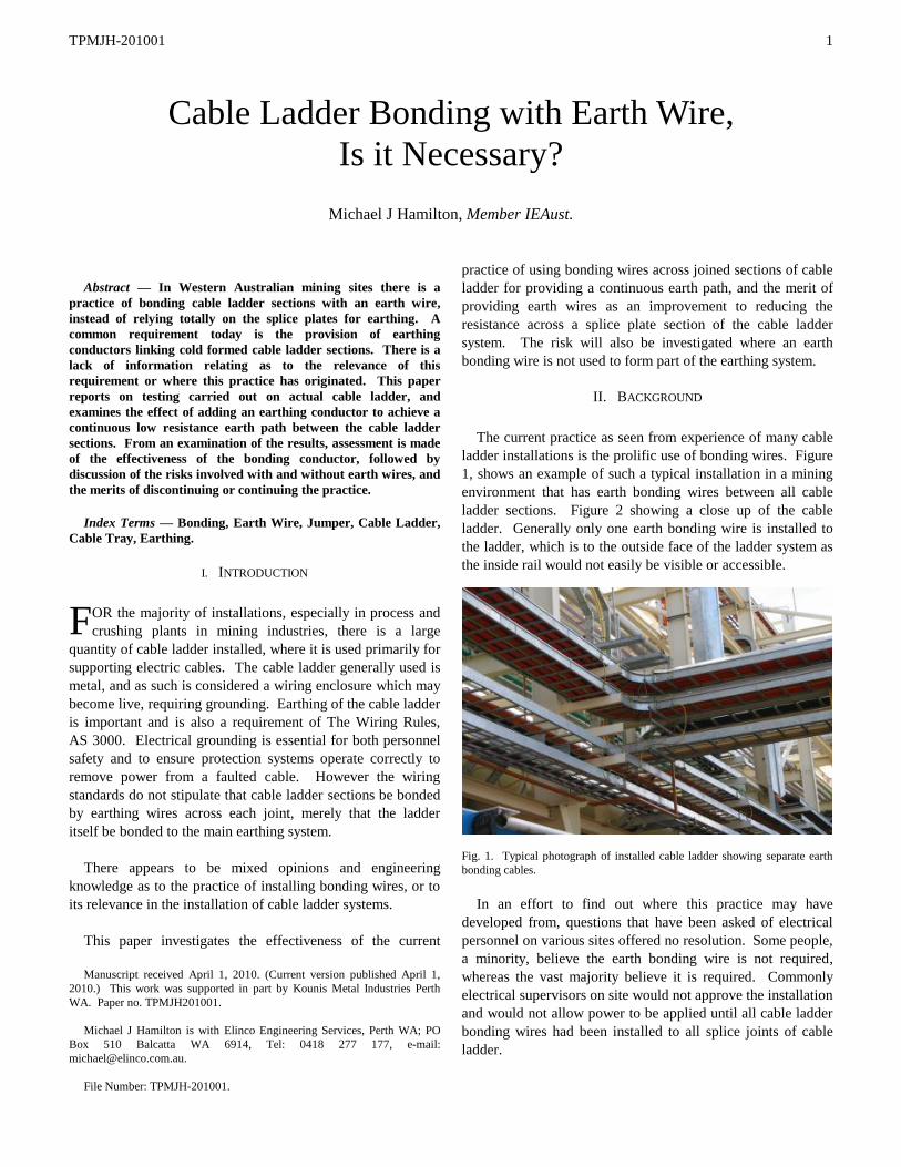
The current practice as seen from experience of many cable
ladder installations is the prolific use of bonding wires. Figure
1, shows an example of such a typical installation in a mining
environment that has earth bonding wires between all cable
ladder sections. Figure 2 showing a close up of the cable
ladder. Generally only one earth bonding wire is installed to
the ladder, which is to the outside face of the ladder system as
the inside rail would not easily be visible or accessible.
Fig. 1. Typical photograph of installed cable ladder showing separate earth
bonding cables.
In an effort to find out where this practice may have
developed from, questions that have been asked of electrical
personnel on various sites offered no resolution. Some people,
a minority, believe the earth bonding wire is not required,
whereas the vast majority believe it is required. Commonly
electrical supervisors on site would not approve the installation
and would not allow power to be applied until all cable ladder
bonding wires had been installed to all splice joints of cable
ladder.
Cable Ladder Bonding with Earth Wire,
Is it Necessary?
Michael J Hamilton, Member IEAust.
F
TPMJH-201001
2
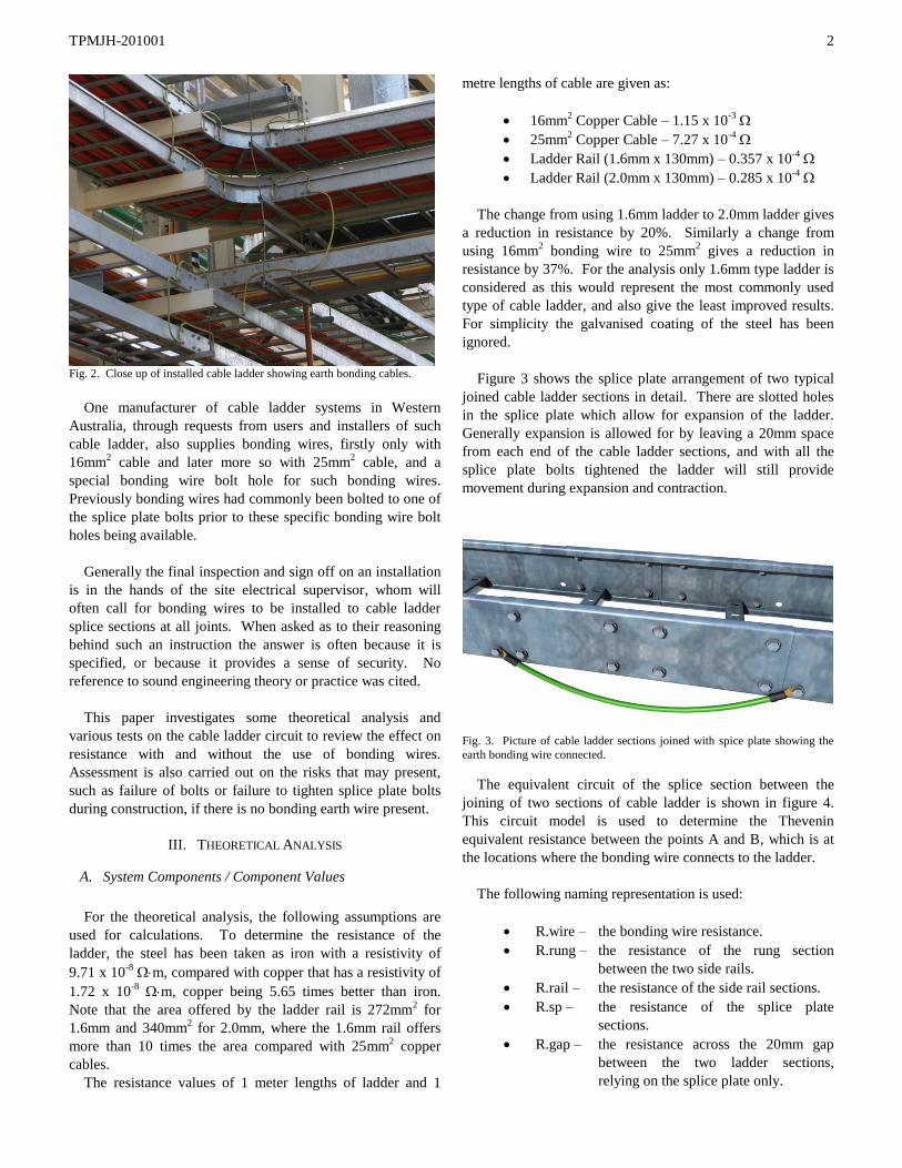
Fig. 2. Close up of installed cable ladder showing earth bonding cables.
One manufacturer of cable ladder systems in Western
Australia, through requests from users and installers of such
cable ladder, also supplies bonding wires, firstly only with
16mm2 cable and later more so with 25mm
2 cable, and a
special bonding wire bolt hole for such bonding wires.
Previously bonding wires had commonly been bolted to one of
the splice plate bolts prior to these specific bonding wire bolt
holes being available.
Generally the final inspection and sign off on an installation
is in the hands of the site electrical supervisor, whom will
often call for bonding wires to be installed to cable ladder
splice sections at all joints. When asked as to their reasoning
behind such an instruction the answer is often because it is
specified, or because it provides a sense of security. No
reference to sound engineering theory or practice was cited.
This paper investigates some theoretical analysis and
various tests on the cable ladder circuit to review the effect on
resistance with and without the use of bonding wires.
Assessment is also carried out on the risks that may present,
such as failure of bolts or failure to tighten splice plate bolts
during construction, if there is no bonding earth wire present.
III. THEORETICAL ANALYSIS
A. System Components / Component Values
For the theoretical analysis, the following assumptions are
used for calculations. To determine the resistance of the
ladder, the steel has been taken as iron with a resistivity of
9.71 x 10⁻⁸
m, compared with copper that has a resistivity of
1.72 x 10⁻⁸
m, copper being 5.65 times better than iron.
Note that the area offered by the ladder rail is 272mm2 for
1.6mm and 340mm2 for 2.0mm, where the 1.6mm rail offers
more than 10 times the area compared with 25mm2 copper
cables.
The resistance values of 1 meter lengths of ladder and 1
metre lengths of cable are given as:
16mm2 Copper Cable – 1.15 x 10
-3
25mm2 Copper Cable – 7.27 x 10
-4
Ladder Rail (1.6mm x 130mm) – 0.357 x 10⁻⁴
Ladder Rail (2.0mm x 130mm) – 0.285 x 10⁻⁴
The change from using 1.6mm ladder to 2.0mm ladder gives
a reduction in resistance by 20%. Similarly a change from
using 16mm2 bonding wire to 25mm
2 gives a reduction in
resistance by 37%. For the analysis only 1.6mm type ladder is
considered as this would represent the most commonly used
type of cable ladder, and also give the least improved results.
For simplicity the galvanised coating of the steel has been
ignored.
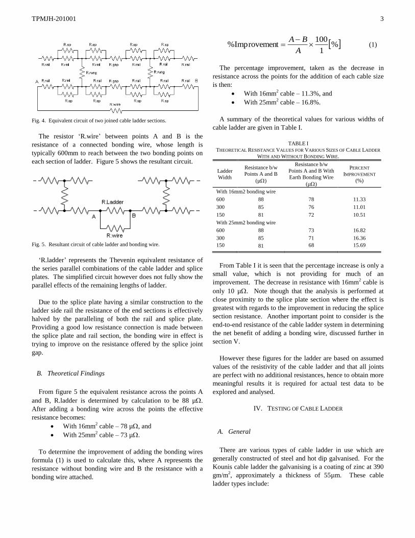
Figure 3 shows the splice plate arrangement of two typical
joined cable ladder sections in detail. There are slotted holes
in the splice plate which allow for expansion of the ladder.
Generally expansion is allowed for by leaving a 20mm space
from each end of the cable ladder sections, and with all the
splice plate bolts tightened the ladder will still provide
movement during expansion and contraction.
Fig. 3. Picture of cable ladder sections joined with spice plate showing the
earth bonding wire connected.
The equivalent circuit of the splice section between the
joining of two sections of cable ladder is shown in figure 4.
This circuit model is used to determine the Thevenin
equivalent resistance between the points A and B, which is at
the locations where the bonding wire connects to the ladder.
The following naming representation is used:
R.wire – the bonding wire resistance.
R.rung – the resistance of the rung section
between the two side rails.
R.rail – the resistance of the side rail sections.
R.sp – the resistance of the splice plate
sections.
R.gap – the resistance across the 20mm gap
between the two ladder sections,
relying on the splice plate only.
TPMJH-201001
3
Fig. 4. Equivalent circuit of two joined cable ladder sections.
The resistor ‘R.wire’ between points A and B is the
resistance of a connected bonding wire, whose length is
typically 600mm to reach between the two bonding points on
each section of ladder. Figure 5 shows the resultant circuit.
Fig. 5. Resultant circuit of cable ladder and bonding wire.
‘R.ladder’ represents the Thevenin equivalent resistance of
the series parallel combinations of the cable ladder and splice
plates. The simplified circuit however does not fully show the
parallel effects of the remaining lengths of ladder.
Due to the splice plate having a similar construction to the
ladder side rail the resistance of the end sections is effectively
halved by the paralleling of both the rail and splice plate.
Providing a good low resistance connection is made between
the splice plate and rail section, the bonding wire in effect is
trying to improve on the resistance offered by the splice joint
gap.
B. Theoretical Findings
From figure 5 the equivalent resistance across the points A
and B, R.ladder is determined by calculation to be 88 µ.
After adding a bonding wire across the points the effective
resistance becomes:
With 16mm2 cable – 78 µ, and
With 25mm2 cable – 73 µ.
To determine the improvement of adding the bonding wires
formula (1) is used to calculate this, where A represents the
resistance without bonding wire and B the resistance with a
bonding wire attached.
%1
100tImprovemen%
A
BA (1)
The percentage improvement, taken as the decrease in
resistance across the points for the addition of each cable size
is then:
With 16mm2 cable – 11.3%, and
With 25mm2 cable – 16.8%.
A summary of the theoretical values for various widths of
cable ladder are given in Table I.
TABLE I
THEORETICAL RESISTANCE VALUES FOR VARIOUS SIZES OF CABLE LADDER
WITH AND WITHOUT BONDING WIRE.
Ladder
Width
Resistance b/w
Points A and B
(µ)
Resistance b/w
Points A and B With
Earth Bonding Wire
(µ)
PERCENT
IMPROVEMENT
(%)
With 16mm2 bonding wire
600 88 78 11.33
300 85 76 11.01
150 81 72 10.51
With 25mm2 bonding wire
600 88 73 16.82
300 85 71 16.36
150 81 68 15.69
From Table I it is seen that the percentage increase is only a
small value, which is not providing for much of an
improvement. The decrease in resistance with 16mm2 cable is
only 10 µ. Note though that the analysis is performed at
close proximity to the splice plate section where the effect is
greatest with regards to the improvement in reducing the splice
section resistance. Another important point to consider is the
end-to-end resistance of the cable ladder system in determining
the net benefit of adding a bonding wire, discussed further in
section V.
However these figures for the ladder are based on assumed
values of the resistivity of the cable ladder and that all joints
are perfect with no additional resistances, hence to obtain more
meaningful results it is required for actual test data to be
explored and analysed.
IV. TESTING OF CABLE LADDER
A. General
There are various types of cable ladder in use which are
generally constructed of steel and hot dip galvanised. For the
Kounis cable ladder the galvanising is a coating of zinc at 390
gm/m2, approximately a thickness of 55µm. These cable
ladder types include:
TPMJH-201001
4
3/50 (NEMA 16A), 1.6mm thickness, 100mm high rails
4/70L (NEMA 20B), 1.6mm thickness, 130mm high rails
4/70 (NEMA 20B), 2.0mm thickness, 130mm high rails
5/112 (NEMA 20C), 2.0mm thickness, 146mmm high rails
The most common cable ladder used in mining sites is the
heavy duty type NEMA 20B. The NEMA 20B to Australian
rated ladder represents the Kounis 4/70L using 1.6mm steel
thickness and 4/70 uses 2mm steel thickness, where the 2mm
type ladder is being used predominantly in cyclone prone
areas. For the tests the 1.6mm steel ladder 4/70L will be used
for determining the effect of the bonding wire, as this will be
more common than with the 2mm ladder construction. Also
the 2mm ladder will give improved results over the 1.6mm
ladder tests.
The purpose of the testing is to determine the reduction in
resistance across the splice joint with the addition of the earth
bonding wire, and to determine if the bonding wire provides an
advantage in various scenarios.
B. Method of Testing
The measurement points for the tests have been taken at 1
meter distance from each end of the ladder sections with a gap
between the two ladder sections of 20mm as would be
maintained in an installation to allow for expansion. The
measurement points therefore are 2.02m apart.
The removal of bolts is performed by removing the outer
bolts and working in a clockwise direction on the left side and
an anticlockwise direction on the right side. Bolts are
removed from the front and rear splice plate. Where ‘a bolt is
removed’, it refers to one front and one rear bolt being
removed. Where ‘bolts are removed from one side’ this refers
to the right side section only, both from the front and back.
The various tests are performed with finger tight and torque
tight bolts. The torque for tight bolts is maintained at 28Nm,
the nominal torque value for 10mm bolts. For the finger tight
bolts, the bolts were screwed to a point where the nut and
washer made contact with the ladder, just nipped up by the
unassisted fingers of one hand.
Each set of the tests were performed without a bonding wire
attached, and then with the bonding wire attached. Where the
bonding wire is attached, the bolts securing the bonding wire
are always tightened with a toque wrench.
The tests have been carried out using a Megger digital low
resistance meter (Ductor tester) with the measuring current set
at 10Amps, giving a range of 1.999m and an accuracy of
±0.2%, ±0.2µ.
The tests have been carried out on short lengths of ladder,
only 2 meters long. The effect this will have on the results will
be to raise the resistance values slightly as paralleling effects
of the ladder are reduced due to the remaining 4 meters of
ladder not being present.
C. Test Results
Tables II and III give the test results from the series of tests
carried out on 600mm wide cable ladder, and Tables IV and V
for 300mm wide ladder. Where tests include an earth bonding
wire, the size of the cable is 16mm2.
TABLE II
RESISTANCE TEST RESULTS FOR 600MM WIDE LADDER
WITH FINGER TIGHT BOLTS.
Bolts
Finger
Tight
Resistance Without
Earth Bonding Wire
(µ)
Resistance With
Earth Bonding
Wire (µ)
Percentage
Improvement
Bolts In Splice Plate - 1 Side Only
4 601.2 532.6 11.41%
3 598.1 534.5 10.63%
2 606.1 536.7 11.45%
1 515.7 540.7 -4.85%
Bolts In Splice Plate – 2 Sides
4 573.3 537.7 6.21%
3 606.9 552.7 8.93%
2 630.5 560.7 11.07%
1 662.7 603.9 8.87%
TABLE III
RESISTANCE TEST RESULTS FOR 600MM WIDE LADDER
WITH TIGHTENED BOLTS.
Bolts
Tight
Resistance Without
Earth Bonding Wire
(µ)
Resistance With
Earth Bonding
Wire (µ)
Percentage
Improvement
Bolts In Splice Plate - 1 Side Only
4 481.0 472.8 1.70%
3 483.2 474.8 1.74%
2 489.9 480.8 1.86%
1 496.4 485.5 2.20%
Bolts In Splice Plate - 2 Sides
4 482.0 472.3 2.01%
3 485.5 475.5 2.06%
2 497.4 485.7 2.35%
1 515.8 500.9 2.89%
Table VI shows the results of tests conducted with the full
set of bolts in the splice plates and comparing the use of
16mm2 bonding wire with 25mm
2.
Table VII gives results to further tests on independent
sections of ladder and earth bonding wire. Due to the
complexity, theoretical values for 1 and 2 meter sections of
ladder have not been determined.
TPMJH-201001
5
TABLE IV
RESISTANCE TEST RESULTS FOR 300MM WIDE LADDER
WITH FINGER TIGHT BOLTS.
Bolts
Finger
Tight
Resistance Without
Earth Bonding Wire
(µ)
Resistance With
Earth Bonding
Wire (µ)
Percentage
Improvement
Bolts In Splice Plate - 1 Side Only
4 534.1 510.4 4.44%
3 537.8 511.1 4.96%
2 544.6 515.3 5.38%
1 543.1 511.9 5.74%
Bolts In Splice Plate - 2 Sides
4 530.0 504.2 4.87%
3 549.6 512.1 6.82%
2 582.3 525.0 9.84%
1 610.1 542.8 11.03%
TABLE V
RESISTANCE TEST RESULTS FOR 300MM WIDE LADDER
WITH TIGHTENED BOLTS.
Bolts
Tight
Resistance Without
Earth Bonding Wire
(µ)
Resistance With
Earth Bonding
Wire (µ)
Percentage
Improvement
Bolts In Splice Plate - 1 Side Only
4 453.4 446.0 1.63%
3 456.1 447.6 1.86%
2 462.7 454.0 1.88%
1 469.4 458.5 2.32%
Bolts In Splice Plate - 2 Sides
4 453.4 446.0 1.63%
3 457.4 449.8 1.66%
2 470.5 461.8 1.85%
1 484.1 471.4 2.62%
TABLE VI
MISCELLANEOUS TESTS FOR SECTIONS OF LADDER.
Test
Measured
Resistance with
16mm2 Bond wire
(µ)
Measured
Resistance with
25mm2 Bond wire
(µ)
Percentage
Improvement
600mm,
Finger
Tight Bolts
524.9 537.7 2.44%
600mm,
Tight Bolts
472.8 469.6 0.67%
300mm,
Tight Bolts
448.3 445.2 0.69%
TABLE VII
COMPARISONS BETWEEN THEORETICAL AND MEASURED RESISTANCE VALUES
FOR SECTIONS OF 600MM WIDE LADDER AND EARTH WIRE.
Test Theoretical
Resistance (µ)
Measured
Resistance (µ)
Percentage
Error
Splice Plate 230.6 216.8 5.98%
600W Ladder
(1m)
Not Determined 354.4
600W Ladder
(2m)
Not Determined 629.0
300W Ladder
(1m)
Not Determined 323.5
300W Ladder
(2m)
Not Determined 580.7
16mm2 Earth
Wire
736.0 699.5 4.96%
25mm2 Earth
Wire
461.6 476.0 3.12%
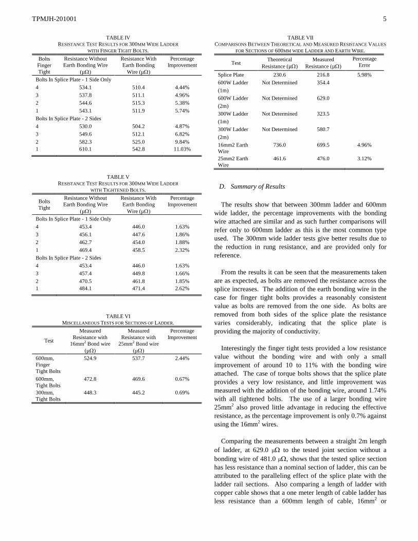
D. Summary of Results
The results show that between 300mm ladder and 600mm
wide ladder, the percentage improvements with the bonding
wire attached are similar and as such further comparisons will
refer only to 600mm ladder as this is the most common type
used. The 300mm wide ladder tests give better results due to
the reduction in rung resistance, and are provided only for
reference.
From the results it can be seen that the measurements taken
are as expected, as bolts are removed the resistance across the
splice increases. The addition of the earth bonding wire in the
case for finger tight bolts provides a reasonably consistent
value as bolts are removed from the one side. As bolts are
removed from both sides of the splice plate the resistance
varies considerably, indicating that the splice plate is
providing the majority of conductivity.
Interestingly the finger tight tests provided a low resistance
value without the bonding wire and with only a small
improvement of around 10 to 11% with the bonding wire
attached. The case of torque bolts shows that the splice plate
provides a very low resistance, and little improvement was
measured with the addition of the bonding wire, around 1.74%
with all tightened bolts. The use of a larger bonding wire
25mm2 also proved little advantage in reducing the effective
resistance, as the percentage improvement is only 0.7% against
using the 16mm2 wires.
Comparing the measurements between a straight 2m length
of ladder, at 629.0 µ to the tested joint section without a
bonding wire of 481.0 µ, shows that the tested splice section
has less resistance than a nominal section of ladder, this can be
attributed to the paralleling effect of the splice plate with the
ladder rail sections. Also comparing a length of ladder with
copper cable shows that a one meter length of cable ladder has
less resistance than a 600mm length of cable, 16mm2 or
TPMJH-201001
6
25mm2. In fact the resistance of ladder would be comparable
to copper cable a little greater than 50mm2. If the resistance of
the splice section under test is compared, we obtain a cable
that would be equivalent to almost 95mm2 copper cable.
V. DISCUSSION
A. General
Theoretical results show that the bonding wire has a small
advantage, around 15% in reducing the resistance at the splice
section, however this result is only based on using an isolated
section of ladder, localised at the splice joint. This is only
across a short distance of 540mm, not a complete ladder
length.
The findings presented from the testing shows that the
bonding wire provides almost no value in reducing the
resistance across the splice plate; however this testing is
performed over an increased distance of 2 meters compared
with the theoretical result. Further, the effectiveness should be
calculated over complete lengths of ladder which are joined
together to obtain a better representation. To determine how
the testing point locations affects the results a look at end to
end resistance is required.
B. End to End Resistance
End-to-end resistance refers to the location of the measuring
points along the length of the ladder system and the effect that
this has when the test points are moved further away from the
splice plate location. Thus assuming a linear resistance value
per meter for the ladder section and another value for the
splice section, located within a small bounded region, and then
comparing this with installing a bonding wire to further reduce
the resistance of the splice region.
The effect then of end-to-end resistance is the change in
resistance as measured as the points are moved outwards from
the centre, and as a result the resistance increases due to the
linear addition of the ladder length the further the
measurement points are moved away, and as such the
advantage (reduction in resistance) of the bonding wire
becomes less the further the measurement points are moved
out. This is further shown by formula (2).
laddersplice RLR totalR (2)
Where;
L = length of ladder minus splice [m]
Rladder is for a 1m section
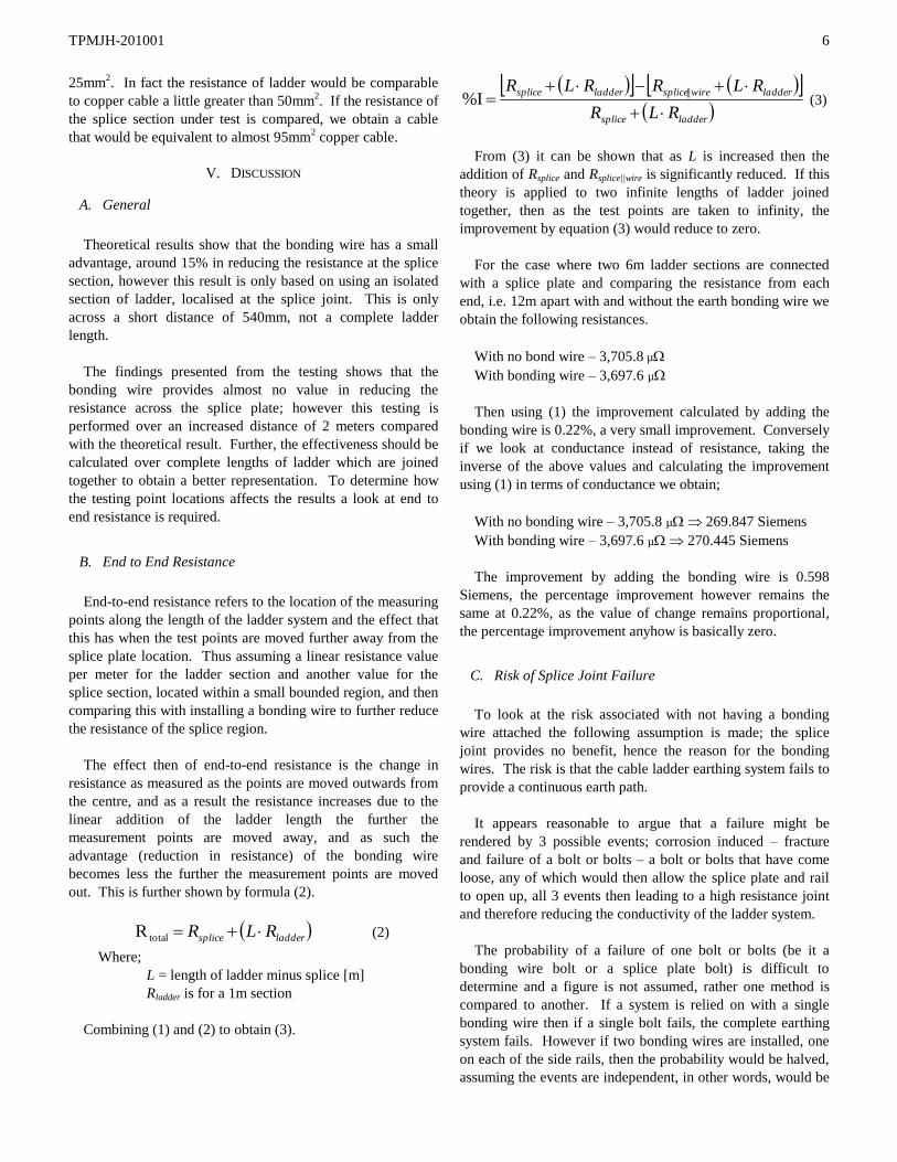
Combining (1) and (2) to obtain (3).
laddersplice
ladderwirespliceladdersplice
RLR
RLRRLR
||%I (3)
From (3) it can be shown that as L is increased then the
addition of Rsplice and Rsplice||wire is significantly reduced. If this
theory is applied to two infinite lengths of ladder joined
together, then as the test points are taken to infinity, the
improvement by equation (3) would reduce to zero.
For the case where two 6m ladder sections are connected
with a splice plate and comparing the resistance from each
end, i.e. 12m apart with and without the earth bonding wire we
obtain the following resistances.
With no bond wire – 3,705.8 µ
With bonding wire – 3,697.6 µ
Then using (1) the improvement calculated by adding the
bonding wire is 0.22%, a very small improvement. Conversely
if we look at conductance instead of resistance, taking the
inverse of the above values and calculating the improvement
using (1) in terms of conductance we obtain;
With no bonding wire – 3,705.8 µ 269.847 Siemens
With bonding wire – 3,697.6 µ 270.445 Siemens
The improvement by adding the bonding wire is 0.598
Siemens, the percentage improvement however remains the
same at 0.22%, as the value of change remains proportional,
the percentage improvement anyhow is basically zero.
C. Risk of Splice Joint Failure
To look at the risk associated with not having a bonding
wire attached the following assumption is made; the splice
joint provides no benefit, hence the reason for the bonding
wires. The risk is that the cable ladder earthing system fails to
provide a continuous earth path.
It appears reasonable to argue that a failure might be
rendered by 3 possible events; corrosion induced – fracture
and failure of a bolt or bolts – a bolt or bolts that have come
loose, any of which would then allow the splice plate and rail
to open up, all 3 events then leading to a high resistance joint
and therefore reducing the conductivity of the ladder system.
The probability of a failure of one bolt or bolts (be it a
bonding wire bolt or a splice plate bolt) is difficult to
determine and a figure is not assumed, rather one method is
compared to another. If a system is relied on with a single
bonding wire then if a single bolt fails, the complete earthing
system fails. However if two bonding wires are installed, one
on each of the side rails, then the probability would be halved,
assuming the events are independent, in other words, would be
TPMJH-201001
7
considered twice as unlikely to fail compared with the single
wire bonding method.
For the case where splice plates are deemed suitable and no
bonding wires exist then there are 8 bolts in each splice plate,
thus for a ladder splice there are 16 bolts in total making an
earth connection. If for the worst case bolts failed only on one
side, 8 bolts for a total failure then the probability of this
system failing would be 8 times less likely to fail than for the
first case relying on a single bonding wire. The splice method
is therefore offering very good odds against a failure of the
earthing system.
For the case where cable ladder is purposely broken, then if
two bonding wires are installed, one to each side rail, the
probability of a complete failure is less likely by a factor of
two. Thus this would be a preferred method for bonding and
earthing in this situation due to the reduced risk involved.
It would be very unlikely that a bolt would fail under normal
conditions, correctly tightened and with minimal vibration.
However failure may be caused by the following; over-torqued
bolts at installation that later fail due to vibration; bolts that
had not been tightened (i.e. finger tight) during installation and
later falling out; corrosion or build up at the splice joint due to
chemicals or mineralised water if the cable ladder has been
installed in severe environments.
The risk of a bolt failure is significantly small under normal
conditions, and can be reduced, by proper tightening and
verification, routine inspection and maintenance which would
also affect any bonding wires being used.
VI. PROBING FURTHER
Investigating other practices from standards of other
organisations gives the following:
NEMA standard VE 2 Section 4.7.1 Cable tray used as an
Equipment Ground Conductor (EGC) states the following;
“The use of aluminium and steel cable trays is permitted as
an Equipment Grounding Conductor per NEC Article 392
when labelled and marked with the available cross sectional
area. (See Table 4-4.) If the cable tray is to be used as an EGC,
bonding jumpers must be installed on both side rails at the
locations illustrated in figures 4.57 through 4.60, unless the
splice plates meet the electrical continuity requirements of
NEMA VE 1. See table 4-5 for minimum sizes of grounding
conductors.
If the connectors are UL Classified bonding jumpers or a
continuous ground are not required.
It is not necessary to install bonding jumpers at standard
rigid aluminium or galvanised steel splice plate connectors or
offset reducing splice plate connectors or any UL Classified
connectors.
For rigid splice plate connections of materials and finishes
other than aluminium or galvanised steel, bonding jumpers
may be required. For example, stainless steel splice plates may
require bonding jumpers depending UL Classification.”
Section 4.8 – Bonding to steel and earth;
“Metallic cable trays shall be bonded to building steel and
earth as supplemental grounding for ground fault protection
and signal grounding (noise prevention). The tray shall be
bonded to building steel and earth, at least every 18m (60 ft).
This is only required when cable tray system is not inherently
bonded (connected) to building steel and earth metallic
support systems”.
NFPA 70 Article 392.7 (B) states;
“Steel or aluminium cable tray systems shall be permitted to
be used as equipment grounding conductors, provided all the
following requirements are met:” Specifically part (4) states,
“Cable tray sections, fittings, and connected raceways are
bonded in accordance with 250.96, using bolted mechanical
connectors or bonding jumpers sized and installed in
accordance with 250.102.”
Cable Tray Institute, Technical Bulletin Number 8, Titled
‘Bonding Jumpers Not Required for Standard Cable Tray
Splice Plates’ states;
“It is not necessary to install bonding jumpers in parallel
with the standard rigid aluminium or steel one-piece metallic
bolted side rail splice plates that are the connections between
the tray sections. Here, the use of bonding jumpers does not
make a safety contribution to a properly installed cable tray
system, and wastes both materials and labour.”
From the above excerpts it is clear that other standards do
not require cable ladder to have additional bonding using earth
wires, and in the case of NFPA and NEC actually allows the
use of cable ladder as an earthing conductor to earth
equipment back to the main earth.
VII. CONCLUSION
For the tested galvanised steel cable ladder, it is concluded
that bonding wires are not required to bond across the standard
splice plates, as the benefit of such a practice is negligible and
provides no addition safety merits.
As for not installing bonding wires, the risk is very low due
to the large number of bolts being used in the splice plates.
The most important bonding connection is the connection of
the cable ladder system to the main earth. Splice plate
bonding wires need only be installed where gaps have been left
in the cable ladder to reinstate a continuous earthed ladder
system.
TPMJH-201001
8
VIII. PROPOSED INSTALLATION PRACTICE
In light of the findings from the results of cable ladder
testing, discussions and further information, the following
points are put forward as proposed installation guidelines for
installing cable ladder.
Cable ladder shall be earthed back to the main earthing
system via two main earth conductors, or via one earth
conductor with a loop installed to each side rail.
Bonding between cable ladder sections is provided with
the slice plates and no additional earth wire conductors
are required.
Where cable ladder sections are separated and are not
joined via splice plates, two off earth conductors shall
be provided to maintain a continuous earth.
Where expansion gaps or sliding expansion joints are
used a bonding earth wire shall be installed to maintain
a continuous earth.
Where adjustable splice plates are used, these shall
include an earth bonding cable unless the plates meet
continuity requirements, (as per NEMA Standard VE
1).
Develop/use a testing or inspection procedure to ensure
that spice plate bolts have been tightened correctly after
installation has been completed.
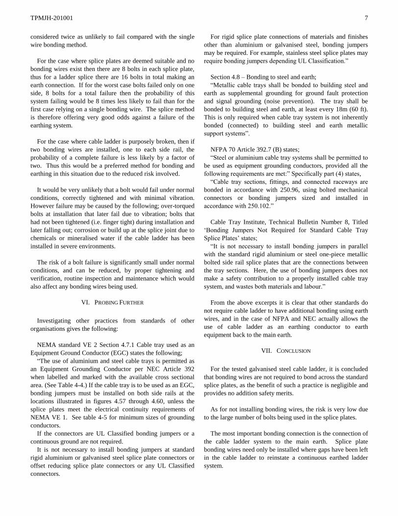
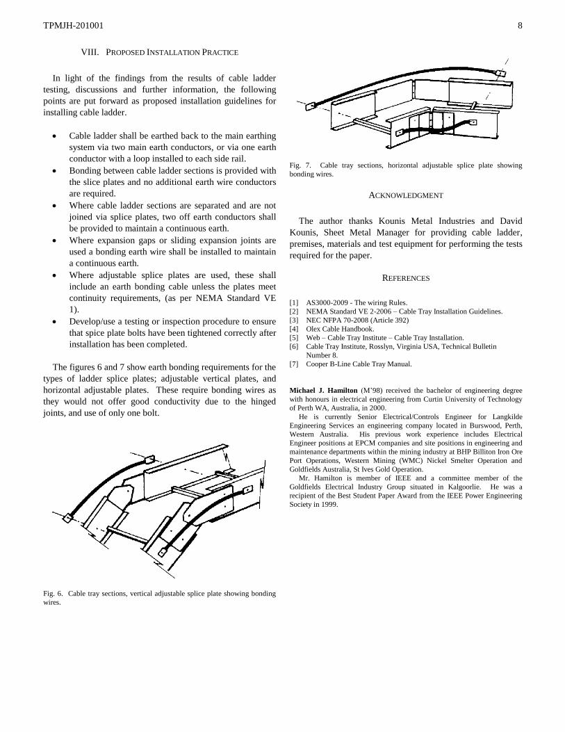
The figures 6 and 7 show earth bonding requirements for the
types of ladder splice plates; adjustable vertical plates, and
horizontal adjustable plates. These require bonding wires as
they would not offer good conductivity due to the hinged
joints, and use of only one bolt.
Fig. 6. Cable tray sections, vertical adjustable splice plate showing bonding
wires.
Fig. 7. Cable tray sections, horizontal adjustable splice plate showing
bonding wires.
ACKNOWLEDGMENT
The author thanks Kounis Metal Industries and David
Kounis, Sheet Metal Manager for providing cable ladder,
premises, materials and test equipment for performing the tests
required for the paper.
REFERENCES
[1] AS3000-2009 - The wiring Rules.
[2] NEMA Standard VE 2-2006 – Cable Tray Installation Guidelines.
[3] NEC NFPA 70-2008 (Article 392)
[4] Olex Cable Handbook.
[5] Web – Cable Tray Institute – Cable Tray Installation.
[6] Cable Tray Institute, Rosslyn, Virginia USA, Technical Bulletin
Number 8.
[7] Cooper B-Line Cable Tray Manual.
Michael J. Hamilton (M’98) received the bachelor of engineering degree
with honours in electrical engineering from Curtin University of Technology
of Perth WA, Australia, in 2000.
He is currently Senior Electrical/Controls Engineer for Langkilde
Engineering Services an engineering company located in Burswood, Perth,
Western Australia. His previous work experience includes Electrical
Engineer positions at EPCM companies and site positions in engineering and
maintenance departments within the mining industry at BHP Billiton Iron Ore
Port Operations, Western Mining (WMC) Nickel Smelter Operation and
Goldfields Australia, St Ives Gold Operation.
Mr. Hamilton is member of IEEE and a committee member of the
Goldfields Electrical Industry Group situated in Kalgoorlie. He was a
recipient of the Best Student Paper Award from the IEEE Power Engineering
Society in 1999.