Capillary Wire Bonding - nordson.com · 6 Capillary Wire Bonding From the historical standpoint,...
36
capillaries 5 4544 McGrath Street Ventura, CA 93003 [email protected] www.gaisertool.com CoorsTek, Inc. Gaiser Products Group Tel Fax +1 805.644.5583 +1 805.644.2013 wedges tab tools die attach other Capillary Wire Bonding A typical step by step overview of the wire bonding process showing the formation of the free air ball, ball bond, stitch bond, and concluding with the reformation of the next free air ball. 1. The bonding process begins with a threaded capillary. 2. Electrical Flame Off (EFO) forms the free air ball. 3. The capillary captures the Free Air Ball in the Chamfer Diameter and descends to the Bond Site. 4. Force and Ultrasonic Energy are applied over Time and the Ball Bond is made. 5. The Looping Sequence 6. Force and Ultrasonic Energy are applied over Time to make the Stitch Bond. 7. The capillary rises with the Wire Clamps off for a specific distance. 8. The Wire Clamps are applied and the wire breaks away from the 2nd Bond leaving a specific tail length. 9. The Tail Length after breaking away from the 2nd Bond. 10. The EFO forms the next Free Air Ball and the cycle begins again. Preferred Failure Modes Undesireable Failure modes Tail Length Position #1) Lifted Ball 2) Neck Break 3) Mid-Span Break 2) Heel Break 5) Lifted Stitch The Ball Bonding Process Mid-Span Break (Bond Strength exceeds • Wire Tensile Strength) Neck Break at Heat Affected Zone (HAZ) • Heel Break • Lifted Stitch • Lifted Ball •
Transcript of Capillary Wire Bonding - nordson.com · 6 Capillary Wire Bonding From the historical standpoint,...
capi
llarie
s
54544 McGrath StreetVentura, CA 93003
[email protected] www.gaisertool.com
CoorsTek, Inc.Gaiser Products Group
TelFax
+1 805.644.5583+1 805.644.2013
wed
ges
tab
tool
sdi
e at
tach
othe
r
Tail Length
Position #1) Lifted Ball
2) Neck Break
3) Mid-Span Break
2) Heel Break5) Lifted Stitch
Capillary Wire Bonding
A typical step by step overview of the wire bonding process showing the formation of the free air ball, ball bond, stitch bond, and concluding with the reformation of the next free air ball.
1. The bonding process begins with a threaded capillary.
2. Electrical Flame Off (EFO) forms the free air ball.
3. The capillary captures the Free Air Ball in the Chamfer Diameter and descends to the Bond Site.
4. Force and Ultrasonic Energy are applied over Time and the Ball Bond is made.
5. The Looping Sequence 6. Force and Ultrasonic Energy are applied over Time to make the Stitch Bond.
7. The capillary rises with the Wire Clamps off for a specific distance.
8. The Wire Clamps are applied and the wire breaks away from the 2nd Bond leaving a specific tail length.
9. The Tail Length after breaking away from the 2nd Bond.
10. The EFO forms the next Free Air Ball and the cycle begins again.
Preferred Failure Modes Undesireable Failure modes
Tail Length
Position #1) Lifted Ball
2) Neck Break
3) Mid-Span Break
2) Heel Break5) Lifted Stitch
Tail Length
Position #1) Lifted Ball
2) Neck Break
3) Mid-Span Break
2) Heel Break5) Lifted Stitch
Tail Length
Position #1) Lifted Ball
2) Neck Break
3) Mid-Span Break
2) Heel Break5) Lifted Stitch
Tail Length
Position #1) Lifted Ball
2) Neck Break
3) Mid-Span Break
2) Heel Break5) Lifted Stitch
Tail Length
Position #1) Lifted Ball
2) Neck Break
3) Mid-Span Break
2) Heel Break5) Lifted Stitch
Tail Length
Position #1) Lifted Ball
2) Neck Break
3) Mid-Span Break
2) Heel Break5) Lifted Stitch
Tail Length
Position #1) Lifted Ball
2) Neck Break
3) Mid-Span Break
2) Heel Break5) Lifted Stitch
Tail Length
Position #1) Lifted Ball
2) Neck Break
3) Mid-Span Break
2) Heel Break5) Lifted Stitch
Tail Length
Position #1) Lifted Ball
2) Neck Break
3) Mid-Span Break
2) Heel Break5) Lifted Stitch
Tail Length
Position #1) Lifted Ball
2) Neck Break
3) Mid-Span Break
2) Heel Break5) Lifted Stitch
The Ball Bonding Process
Mid-Span Break (Bond Strength exceeds •Wire Tensile Strength)Neck Break at Heat Affected Zone (HAZ)•Heel Break•
Lifted Stitch•Lifted Ball•
6
Capillary Wire Bonding
From the historical standpoint, Au-Al semiconductor wire bonding was done only by heat and pressure (thermo com-pression) using heat-drawn glass capillaries which provided a metal-to-metal weld. This was an acceptable process for some years but the 300ºC plus temperatures and relatively high bonding forces became a problem with thinner chips, device sensitivity, lead frame oxidation, etc.
Capillary material advancements, initially Tungsten Carbide, lead to more robust and dimensionally consistent capillaries. They also allowed the reduction of bonding temperatures for sensitive devices by transferring the heat directly to the capillary. Capillary heaters were a popular form of bonding heat sensitive devices. However, the heat transferred via the metal capillary created a new problem by exaggerating grain growth at the ball neck region. The end result was lower pull values as the temperature of the capillary was increased to offset reductions in the stage temperature.
The early bonding process depended on Hydrogen-Oxygen based torches to form a free air ball. This torch mechanism, if not set properly, exhibited a tendency to cause early oxida-tion of the WC (Tungsten Carbide) capillaries. This prompted Gaiser to search for new solutions which resulted in our invention of the ceramic capillary. With the invention of the ultrasonic transducer, acoustic energy was introduced into the equation, greatly improving bond strengths and bondability (Thermosonic and Ultrasonic Bonding).
Around the late 1970’s, someone thought that adding an ul-trasonic vibration to the capillary along with the usual param-eters that the “scrubbing” action of the metal surfaces would improve the bond reliability. As luck would have it, it also lowered bonding temperature requirements and created better Au-Al reactivity so the Thermosonic process was born.
Typical processes were designed around 60 kHz for many years and still remain so, even today. In the late 1980’s, a group of bonding scientists pioneered a revolutionary improvement in the ball bond process by increasing the transducer frequencies beyond the standard 60 kHz. Their work set the foundation for high-frequency processes where transducer frequencies range from 90 to 250 kHz covering a wide field of applications. Capillary materials had to be modified to better utilize the necessary changes in process application as well as being better tuned to the higher fre-quency transducers.
Following are the basic requirements for successful ball bonding:
Factors such as bond pad size, bond pad pitch, wire diameter, bonding surfaces, metallization, loop height, loop length, bonder speed and accuracy, and package design will effect the capillary chosen for a wire-bonding application. CoorsTek offers a number of standard industry capillary designs as well as the ability to customize part numbers for individual applications.
The Ball Bonding Capillary-A Brief History
Basic Requirements for SuccessfulBall Bonding
A maintained ball bonder and a 1. knowledge of its operationAn appropriate part number capillary 2. in functional conditionQuality wire property handled, correct 3. hardness, elongation, and tensile strengthOptimized tuning of the bonder (time, 4. force, and ultrasonic power)Heat - adequate stage temperature, paying 5. special attention to material properties [i.e Glass Transition Temperature (Tg)]Good metallization6. Clean metallization7. A securely clamped and leveled workpiece8.
capi
llarie
s
74544 McGrath StreetVentura, CA 93003
[email protected] www.gaisertool.com
CoorsTek, Inc.Gaiser Products Group
TelFax
+1 805.644.5583+1 805.644.2013
wed
ges
tab
tool
sdi
e at
tach
othe
r
0.375 / 9.52mm0.437 / 11.1mm0.470 / 11.94mm0.625 / 15.88mm0.750 / 19.05mm±0.005 / .13mm
20°(OPTIONAL)
Ø0.06241.58mm
Ø0.0300.76mm
30°(STANDARD)
H
B
T
OR
IC ANGLE
ICFACE
ANGLE
Capillary Wire Bonding
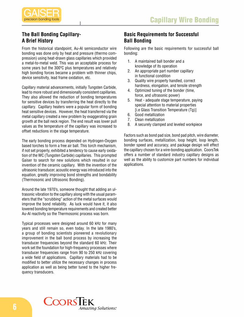
Capillaries have two basic sets of industry standard dimen-sional characteristics: large geometry and small geometry. Large geometry dimensions generally refer to the shank, back hole, and cone. Small geometry dimensions refer to the tip details.
Virtually all capillaries in use today are 1/16 inch diameter (0.0625 in./1.58mm). The most common capillary length is 0.437 in./11.1mm, followed by the 0.375 in./9.52mm length. Also available for the longer lengths are 0.625 in./15.88mm and 0.750 in./19.05mm.
The industry standard cone angle is 30° with 20° and 15° being optional. A 20° cone angle is becoming increasing popular for an all purpose capillary with today’s shrinking packages. Sharper cone angles provide additional clearance in tight packages. Use of a 15° cone angle may result in some loss of ultrasonic energy transfer.
For fine-pitch applications, an angle bottleneck tip design may be required. Most angle bottlenecks have a 10° or 5° angle and are normally 0.006 in./150µm to 0.015 in./380µm high. The angle bottleneck height and angle are driven mainly by the bond pad pitch and loop height of the application. See the fine pitch section for more information.
Shank Diameter (SD)1. Tool Length (L)2. Cone Angle or Main Taper Angle3. Back Hole4.
Figure 1 – Large geometry dimensionsTip Diameter (T)1. Hole Diameter or Size (H)2. Chamfer Diameter (CD or B)3. Inside Chamfer (IC)4. Inside Chamfer Angle (IC Angle)5. Face Angle (Note: may be flat, 0°)6. Outside Radius (OR)7.
Figure 2 – Small (tip) geometry dimensions
Basic Capillary Design Dimensions
Industry standard large geometry dimensions:
Industry standard small geometry dimensions:
8
TT
Capillary Wire Bonding
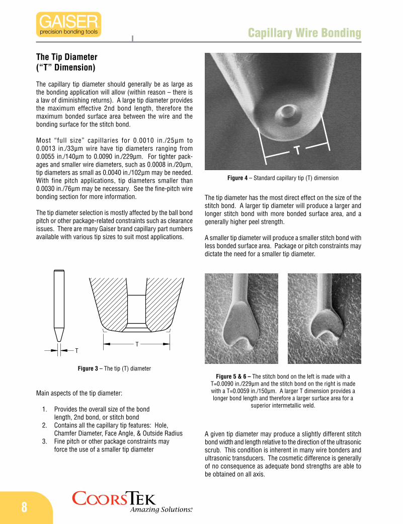
The Tip Diameter(“T” Dimension)
The capillary tip diameter should generally be as large as the bonding application will allow (within reason – there is a law of diminishing returns). A large tip diameter provides the maximum effective 2nd bond length, therefore the maximum bonded surface area between the wire and the bonding surface for the stitch bond.
Most “full size” capillaries for 0.0010 in./25µm to 0.0013 in./33µm wire have tip diameters ranging from 0.0055 in./140µm to 0.0090 in./229µm. For tighter pack-ages and smaller wire diameters, such as 0.0008 in./20µm, tip diameters as small as 0.0040 in./102µm may be needed. With fine pitch applications, tip diameters smaller than 0.0030 in./76µm may be necessary. See the fine-pitch wire bonding section for more information.
The tip diameter selection is mostly affected by the ball bond pitch or other package-related constraints such as clearance issues. There are many Gaiser brand capillary part numbers available with various tip sizes to suit most applications.
A given tip diameter may produce a slightly different stitch bond width and length relative to the direction of the ultrasonic scrub. This condition is inherent in many wire bonders and ultrasonic transducers. The cosmetic difference is generally of no consequence as adequate bond strengths are able to be obtained on all axis.
The tip diameter has the most direct effect on the size of the stitch bond. A larger tip diameter will produce a larger and longer stitch bond with more bonded surface area, and a generally higher peel strength.
A smaller tip diameter will produce a smaller stitch bond with less bonded surface area. Package or pitch constraints may dictate the need for a smaller tip diameter.
Figure 4 – Standard capillary tip (T) dimension
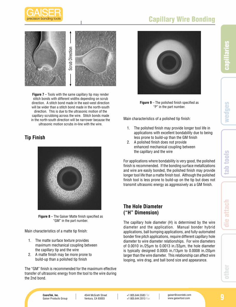
Main aspects of the tip diameter:
Provides the overall size of the bond 1. length, 2nd bond, or stitch bondContains all the capillary tip features: Hole, 2. Chamfer Diameter, Face Angle, & Outside RadiusFine pitch or other package constraints may 3. force the use of a smaller tip diameter
Figure 3 – The tip (T) diameterFigure 5 & 6 – The stitch bond on the left is made with a
T=0.0090 in./229µm and the stitch bond on the right is made with a T=0.0059 in./150µm. A larger T dimension provides a longer bond length and therefore a larger surface area for a
superior intermetallic weld.
T
capi
llarie
s
94544 McGrath StreetVentura, CA 93003
[email protected] www.gaisertool.com
CoorsTek, Inc.Gaiser Products Group
TelFax
+1 805.644.5583+1 805.644.2013
wed
ges
tab
tool
sdi
e at
tach
othe
r
Capillary Wire Bonding
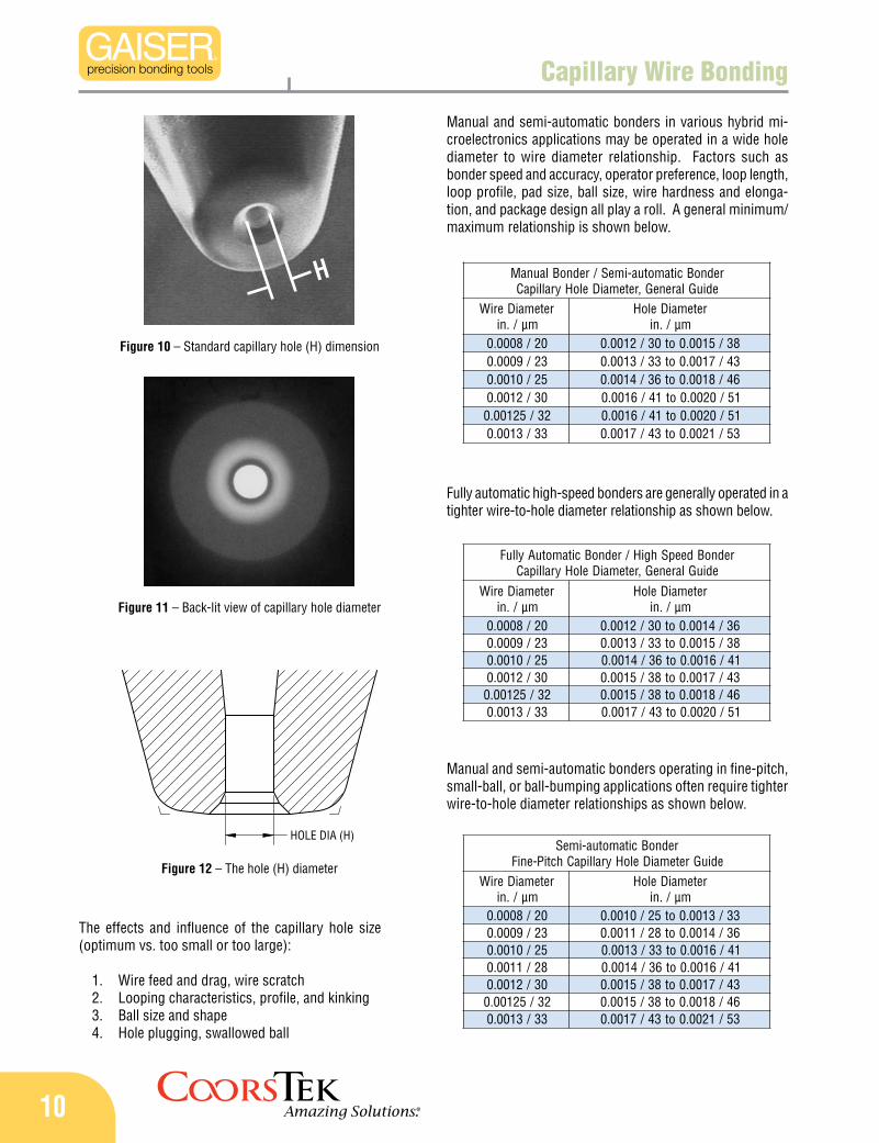
Tip Finish
Figure 7 – Tools with the same capillary tip may render stitch bonds with different widths depending on scrub
direction. A stitch bond made in the east-west direction will be wider than a stitch bond made in the north-south
direction. This is due to the ultrasonic motion of the capillary scrubbing across the wire. Stitch bonds made in the north-south direction will be narrower because the
ultrasonic motion scrubs in-line with the wire.Main characteristics of a polished tip finish:
The polished finish may provide longer tool life in 1. applications with excellent bondability due to being less prone to build-up than the GM finishA polished finish does not provide 2. enhanced mechanical coupling between the capillary and the wire
For applications where bondability is very good, the polished finish is recommended. If the bonding surface metallizations and wire are easily bonded, the polished finish may provide longer tool life than a matte finish tool. Although the polished finish tool is less prone to build-up on the tip but does not transmit ultrasonic energy as aggressively as a GM finish.
Figure 9 – The polished finish specified as “P” in the part number.
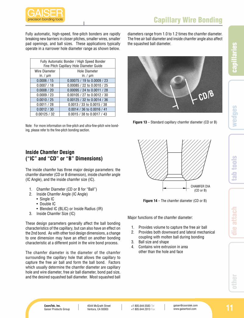
The Hole Diameter(“H” Dimension)
The capillary hole diameter (H) is determined by the wire diameter and the application. Manual bonder hybrid applications, ball bumping applications, and fully-automated bonder fine pitch applications, require different capillary hole diameter to wire diameter relationships. For wire diameters of 0.0010 in./25µm to 0.0013 in./33µm, the hole diameter is typically designed 0.0005 in./13µm to 0.0008 in./20µm larger than the wire diameter. This relationship can affect wire looping, wire drag, and ball bond size and appearance.
Main characteristics of a matte tip finish:
The matte surface texture provides 1. maximum mechanical coupling between the capillary tip and the wireA matte finish may be more prone to 2. build-up than a polished tip finish
The “GM” finish is recommended for the maximum effective transfer of ultrasonic energy from the tool to the wire during the 2nd bond.
Figure 8 – The Gaiser Matte finish specified as “GM” in the part number.
Scru
b Di
rect
ion
10
HOLE DIA (H)
rednoBdeepShgiH/rednoBcitamotuAylluFediuGlareneG,retemaiDeloHyrallipaC
retemaiDeriWmµ/.ni
retemaiDeloHmµ/.ni
02/8000.0 63/4100.0ot03/2100.032/9000.0 83/5100.0ot33/3100.052/0100.0 14/6100.0ot63/4100.003/2100.0 34/7100.0ot83/5100.023/52100.0 64/8100.0ot83/5100.033/3100.0 15/0200.0ot34/7100.0
rednoBcitamotua-imeS/rednoBlaunaMediuGlareneG,retemaiDeloHyrallipaC
retemaiDeriWmµ/.ni
retemaiDeloHmµ/.ni
02/8000.0 83/5100.0ot03/2100.032/9000.0 34/7100.0ot33/3100.052/0100.0 64/8100.0ot63/4100.003/2100.0 15/0200.0ot14/6100.023/52100.0 15/0200.0ot14/6100.033/3100.0 35/1200.0ot34/7100.0
rednoBcitamotua-imeSediuGretemaiDeloHyrallipaChctiPe-niF
retemaiDeriWmµ/.ni
retemaiDeloHmµ/.ni
02/8000.0 33/3100.0ot52/0100.032/9000.0 63/4100.0ot82/1100.052/0100.0 14/6100.0ot33/3100.082/1100.0 14/6100.0ot63/4100.003/2100.0 34/7100.0ot83/5100.023/52100.0 64/8100.0ot83/5100.0
33/3100.0 35/1200.0ot34/7100.0
Capillary Wire Bonding
Manual and semi-automatic bonders in various hybrid mi-croelectronics applications may be operated in a wide hole diameter to wire diameter relationship. Factors such as bonder speed and accuracy, operator preference, loop length, loop profile, pad size, ball size, wire hardness and elonga-tion, and package design all play a roll. A general minimum/maximum relationship is shown below.
Figure 10 – Standard capillary hole (H) dimension
The effects and influence of the capillary hole size (optimum vs. too small or too large):
Wire feed and drag, wire scratch1. Looping characteristics, profile, and kinking2. Ball size and shape3. Hole plugging, swallowed ball4.
Figure 12 – The hole (H) diameter
Figure 11 – Back-lit view of capillary hole diameter
Fully automatic high-speed bonders are generally operated in a tighter wire-to-hole diameter relationship as shown below.
Manual and semi-automatic bonders operating in fine-pitch, small-ball, or ball-bumping applications often require tighter wire-to-hole diameter relationships as shown below.
H
capi
llarie
s
114544 McGrath StreetVentura, CA 93003
[email protected] www.gaisertool.com
CoorsTek, Inc.Gaiser Products Group
TelFax
+1 805.644.5583+1 805.644.2013
wed
ges
tab
tool
sdi
e at
tach
othe
r
CHAMFER DIA (CD or B)
rednoBdeepShgiH/rednoBcitamotuAylluFediuGretemaiDeloHyrallipaChctiPeniF
retemaiDeriWmµ/.ni
retemaiDeloHmµ/.ni
51/6000.0 32/9000.0ot91/57000.081/7000.0 52/0100.0ot22/58000.002/8000.0 82/1100.0ot42/59000.032/9000.0 03/2100.0ot72/50100.052/0100.0 63/4100.0ot23/52100.082/1100.0 83/5100.0ot33/3100.003/2100.0 14/6100.0ot63/4100.023/52100.0 34/7100.0ot83/5100.0
Inside Chamfer Design(“IC” and “CD” or “B” Dimensions)
Fully automatic, high-speed, fine-pitch bonders are rapidly breaking new barriers in closer pitches, smaller wires, smaller pad openings, and ball sizes. These applications typically operate in a narrower hole diameter range as shown below.
Note: For more information on fine-pitch and ultra-fine-pitch wire bond-ing, please refer to the fine-pitch bonding section.
The inside chamfer has three major design parameters: the chamfer diameter (CD or B dimension), inside chamfer angle (IC Angle), and the inside chamfer size (IC).
Chamfer Diameter (CD or B for “Ball”)1. Inside Chamfer Angle (IC Angle) 2. •SingleIC •DoubleIC •BlendedIC(BLIC)orInsideRadius(IR)Inside Chamfer Size (IC)3.
These design parameters generally affect the ball bonding characteristics of the capillary, but can also have an effect on the 2nd bond. As with other tool design dimensions, a change to one dimension may have an effect on another bonding characteristic at a different point in the wire bond process.
The chamfer diameter is the diameter of the chamfer surrounding the capillary hole that allows the capillary to capture the free air ball and form the ball bond. Factors which usually determine the chamfer diameter are capillary hole and wire diameter, free air ball diameter, bond pad size, and the desired squashed ball diameter. Most squashed ball
diameters range from 1.0 to 1.2 times the chamfer diameter. The free air ball diameter and inside chamfer angle also affect the squashed ball diameter.
Major functions of the chamfer diameter:
Provides volume to capture the free air ball1. Provides both downward and lateral mechanical 2. coupling with molten ball during bondingBall size and shape3. Contains wire extrusion in area 4. other than the hole and face
Figure 13 – Standard capillary chamfer diameter (CD or B)
Figure 14 – The chamfer diameter (CD or B)
Capillary Wire Bonding
CD/B
12
90°
45°
F1
F2
F1 = F2
120°
60°
F2
F1
F1 > F2
IC=H
B
ICB-H2
B=2xIC + H
Capillary Wire Bonding
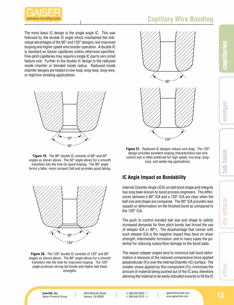
The previous section discussed the basics of the chamfer diameter (CD or B). This section covers the inside chamfer angle (IC Angle) and the remaining component in the equa-tion, the inside chamfer (IC).
Mathematically, the IC value is 1/2 the difference between the chamfer diameter and the hole diameter, or the delta X component of the chamfer surrounding the capillary hole.
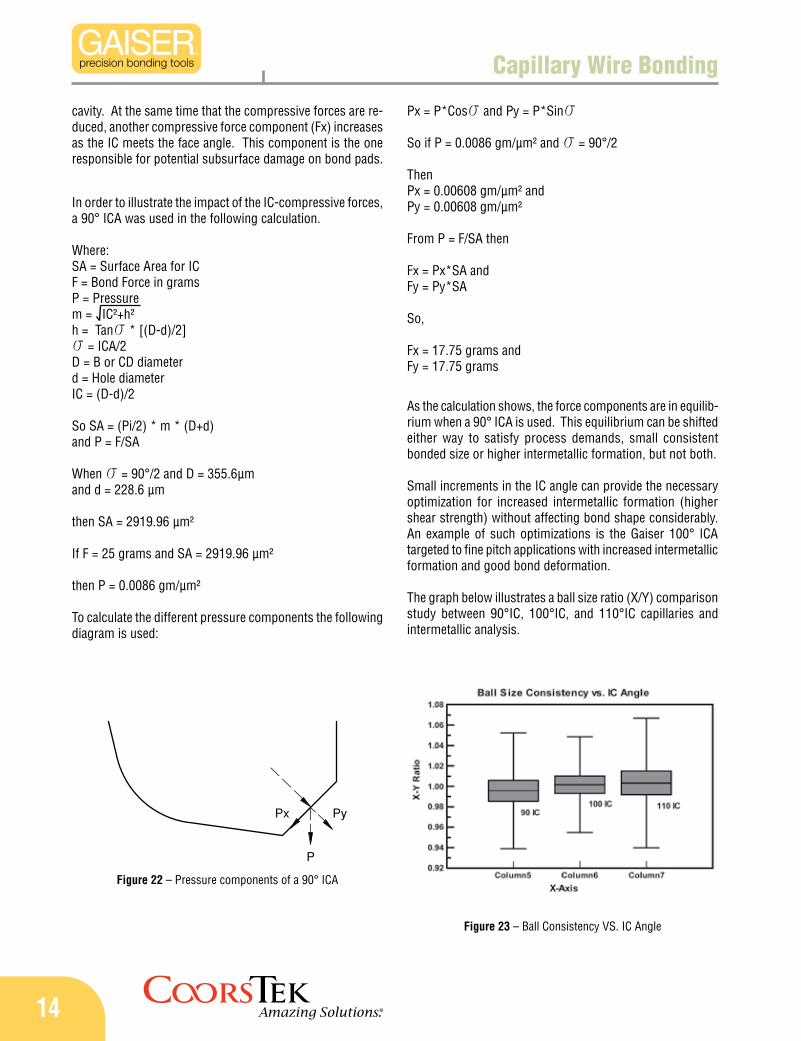
Larger capillaries for 0.00125 in./32µm wire hybrid applications may have an inside chamfer size of up to 0.0010 in./25µm. Medium to small ball capillaries have IC sizes from 0.0006 in./15µm down to 0.0003 in./8µm. Fine pitch capillaries have IC sizes from 0.0004 in./10µm down to as small as 0.00015/4µm. New developments for ultra-fine-pitch capillaries are pushing the envelope to 0.0001 in./2.5µm and below.
Figure 18 – Standard capillary inside chamfer (IC) dimension
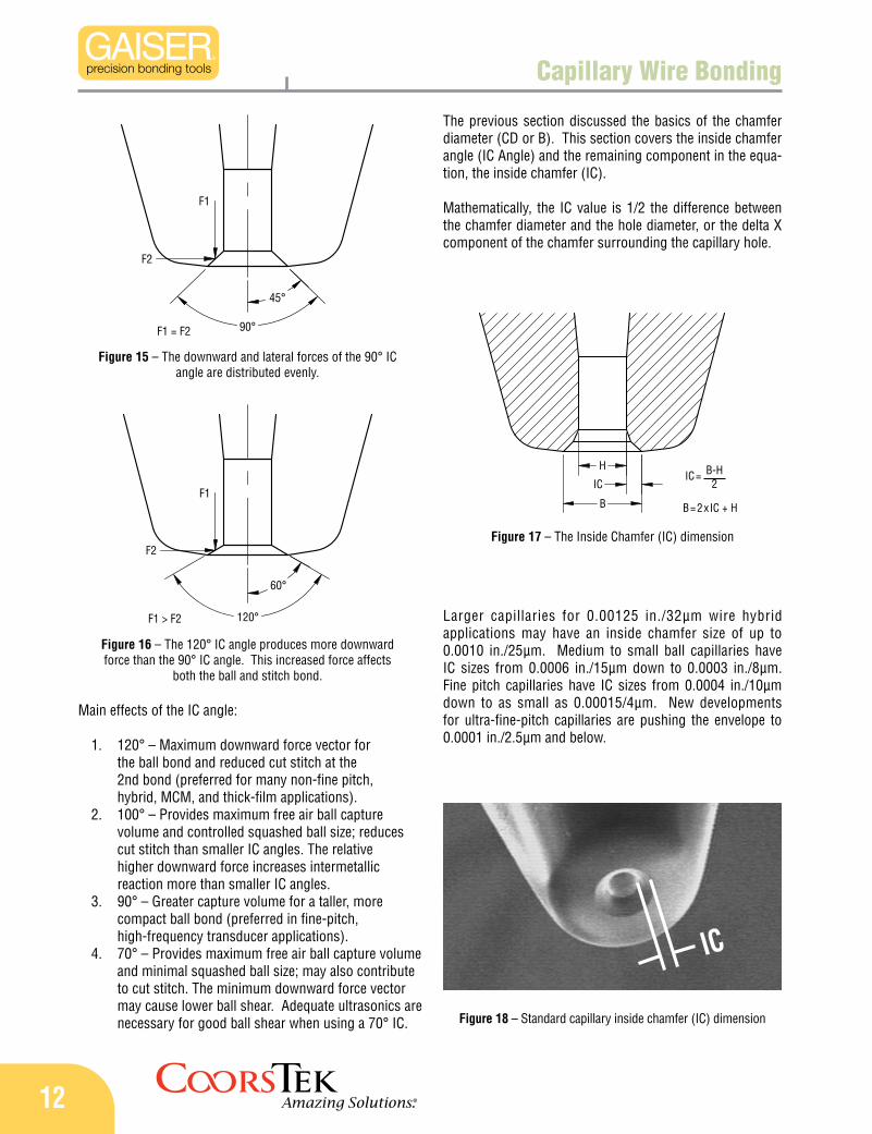
Figure 16 – The 120° IC angle produces more downward force than the 90° IC angle. This increased force affects
both the ball and stitch bond.
Figure 15 – The downward and lateral forces of the 90° IC angle are distributed evenly.
Main effects of the IC angle:
120° – Maximum downward force vector for 1. the ball bond and reduced cut stitch at the 2nd bond (preferred for many non-fine pitch, hybrid, MCM, and thick-film applications).100° – Provides maximum free air ball capture 2. volume and controlled squashed ball size; reduces cut stitch than smaller IC angles. The relative higher downward force increases intermetallic reaction more than smaller IC angles.90° – Greater capture volume for a taller, more 3. compact ball bond (preferred in fine-pitch, high-frequency transducer applications).70° – Provides maximum free air ball capture volume 4. and minimal squashed ball size; may also contribute to cut stitch. The minimum downward force vector may cause lower ball shear. Adequate ultrasonics are necessary for good ball shear when using a 70° IC.
Figure 17 – The Inside Chamfer (IC) dimension
IC
capi
llarie
s
134544 McGrath StreetVentura, CA 93003
[email protected] www.gaisertool.com
CoorsTek, Inc.Gaiser Products Group
TelFax
+1 805.644.5583+1 805.644.2013
wed
ges
tab
tool
sdi
e at
tach
othe
r
90°
50°
120°
80°
90°
120°
Capillary Wire Bonding
IC Angle Impact on Bondability
The most basic IC design is the single angle IC. This was followed by the double IC angle which maintained the indi-vidual advantages of the 90° and 120° designs, but improved looping and higher speed wire bonder operation. A double IC is standard on Gaiser capillaries unless otherwise specified. Fine-pitch capillaries may require a single IC due to very small feature size. Further to the double IC design is the radiused inside chamfer or blended inside radius. Radiused inside chamfer designs are helpful in low-loop, long-loop, long-wire, or high/low bonding applications.
Internal Chamfer Angle (ICA) on ball bond shape and integrity has long been known to bond process engineers. The differ-ences between a 90° ICA and a 120° ICA are clear when the ball size and shape are compared. The 90° ICA provides less squash or deformation on the finished bond as compared to the 120° ICA.
The push to control bonded ball size and shape to satisfy increased demands for finer pitch bonds has forced the use of steeper ICA (< 90°). The disadvantage that comes with such steeper ICA is the negative impact they have on shear strength, intermetallic formation, and in many cases the po-tential for inducing subsurface damage to the bond pads.
The reason steeper angles tend to minimize ball bond defor-mation is because of the reduced compressive force applied perpendicular (Fy) over the Internal Chamfer (IC) surface. The smaller stress applied by this component (Fy) minimizes the amount of material being pushed out of the IC area, therefore allowing the material to be easily extruded inwards to fill the IC
Figure 19. The 90° double IC consists of 90° and 50° angles as shown above. The 50° angle allows for a smooth
transition into the hole for good looping. The 90° angle forms a taller, more compact ball and provides good tailing.
Figure 20. The 120° double IC consists of 120° and 80° angles as shown above. The 80° angle allows for a smooth
transition into the hole for improved looping. The 120° angle produces strong tail bonds and higher ball shear
strengths.
Figure 21. Radiused IC designs reduce wire drag. The 120° design provides excellent looping characteristics and wire
control and is often preferred for high speed, low-loop, long-loop, and spider-leg applications.
14
Capillary Wire Bonding
cavity. At the same time that the compressive forces are re-duced, another compressive force component (Fx) increases as the IC meets the face angle. This component is the one responsible for potential subsurface damage on bond pads.
As the calculation shows, the force components are in equilib-rium when a 90° ICA is used. This equilibrium can be shifted either way to satisfy process demands, small consistent bonded size or higher intermetallic formation, but not both.
Small increments in the IC angle can provide the necessary optimization for increased intermetallic formation (higher shear strength) without affecting bond shape considerably. An example of such optimizations is the Gaiser 100° ICA targeted to fine pitch applications with increased intermetallic formation and good bond deformation.
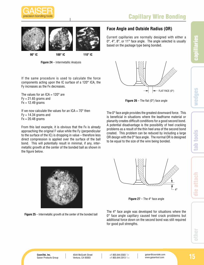
The graph below illustrates a ball size ratio (X/Y) comparison study between 90°IC, 100°IC, and 110°IC capillaries and intermetallic analysis.
Px = P*Coss and Py = P*Sins
So if P = 0.0086 gm/µm² and s = 90°/2
ThenPx = 0.00608 gm/µm² andPy = 0.00608 gm/µm²
From P = F/SA then
Fx = Px*SA and Fy = Py*SA
So,
Fx = 17.75 grams andFy = 17.75 grams
Figure 23 – Ball Consistency VS. IC Angle
Figure 22 – Pressure components of a 90° ICA
In order to illustrate the impact of the IC-compressive forces, a 90° ICA was used in the following calculation.
Where:SA = Surface Area for ICF = Bond Force in gramsP = Pressurem = IC²+h² h = Tans * [(D-d)/2]s = ICA/2D = B or CD diameterd = Hole diameterIC = (D-d)/2
So SA = (Pi/2) * m * (D+d)and P = F/SA
When s = 90°/2 and D = 355.6µmand d = 228.6 µm
then SA = 2919.96 µm²
If F = 25 grams and SA = 2919.96 µm²
then P = 0.0086 gm/µm²
To calculate the different pressure components the following diagram is used:
capi
llarie
s
154544 McGrath StreetVentura, CA 93003
[email protected] www.gaisertool.com
CoorsTek, Inc.Gaiser Products Group
TelFax
+1 805.644.5583+1 805.644.2013
wed
ges
tab
tool
sdi
e at
tach
othe
r
FLAT FACE (0°)
4°
Capillary Wire Bonding
Face Angle and Outside Radius (OR)
Current capillaries are normally designed with either a 0°, 4°, 8°, or 11° face angle. The angle selected is usually based on the package type being bonded.
If the same procedure is used to calculate the force components acting upon the IC surface of a 120° ICA, the Fy increases as the Fx decreases.
The values for an ICA = 120° areFy = 21.65 grams andFx = 12.49 grams
If we now calculate the values for an ICA = 70° thenFy = 14.34 grams andFx = 20.48 grams
From this last example, it is obvious that the Fx is already approaching the original F value while the Fy (perpendicular to the surface of the IC) is dropping in value – therefore less direct compression is applied over the surface of the ball bond. This will potentially result in minimal, if any, inter-metallic growth at the center of the bonded ball as shown in the figure below.
The 0° face angle provides the greatest downward force. This is beneficial in situations where the leadframe material or planarity creates difficult conditions for a good second bond. A potential disadvantage is the possibility of heel cracking problems as a result of the thin heel area of the second bond created. This problem can be reduced by including a large OR design with the 0° face angle. The normal OR is designed to be equal to the size of the wire being bonded.
Figure 24 – Intermetallic Analysis
Figure 25 – Intermetallic growth at the center of the bonded ball
Figure 26 – The flat (0°) face angle
90° IC 100° IC 110° IC
The 4° face angle was developed for situations where the 0° face angle capillary caused heel crack problems but additional force down on the second bond was still required for good pull strengths.
Figure 27 – The 4° face angle
16
8°
11°
LC
POTENTIALWELDMENT AREA
STITCH BONDTAIL
BOND
LOCATION
60°11°
Capillary Wire Bonding
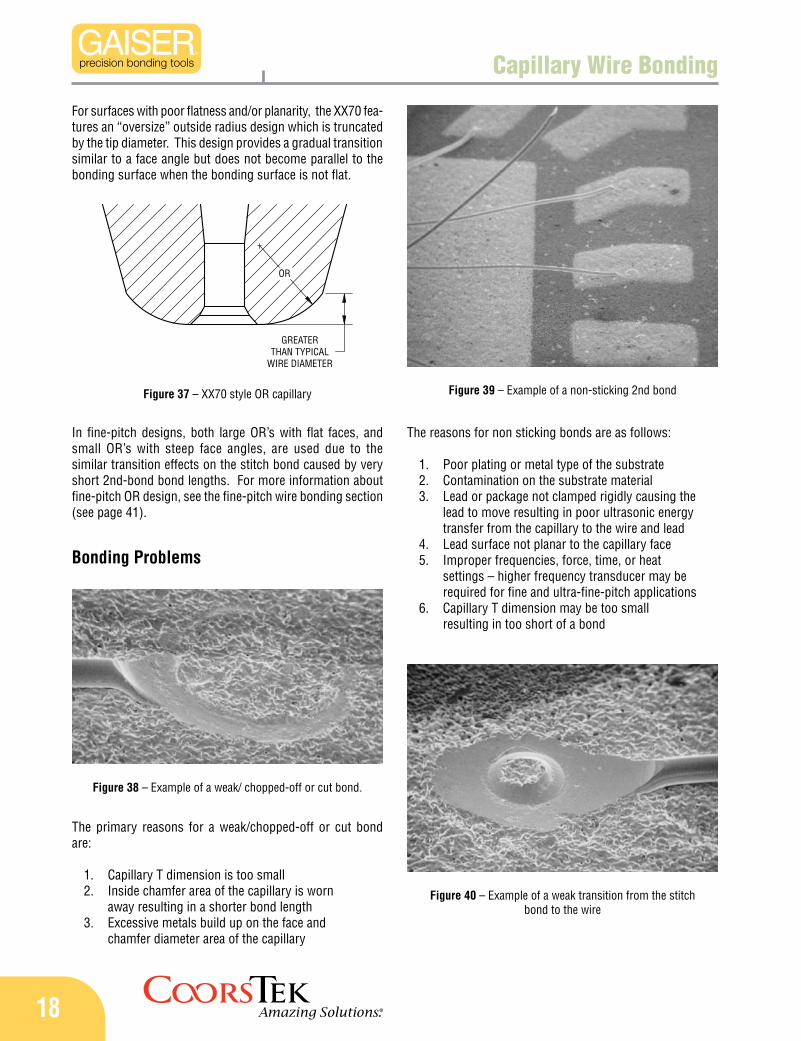
Another way of illustrating stresses is shown in the compari-son below where a fixed-face-angle capillary is compared with a CDR2B type capillary.
The standard face angle capillary shows a Vertical Force component concentrated at the intersection of the IC and Face Angle. If this component is excessive, the results are cut wires resulting in missing balls.
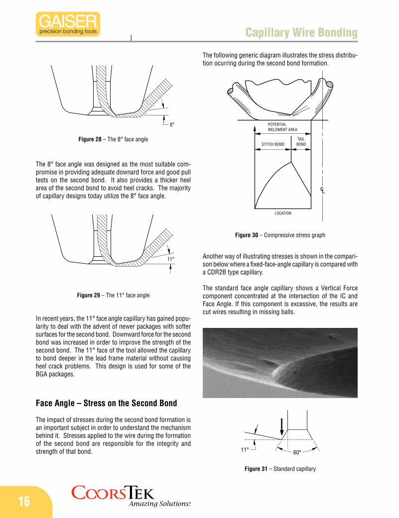
Figure 28 – The 8° face angle
The 8° face angle was designed as the most suitable com-promise in providing adequate downard force and good pull tests on the second bond. It also provides a thicker heel area of the second bond to avoid heel cracks. The majority of capillary designs today utilize the 8° face angle.
Figure 29 – The 11° face angle
In recent years, the 11° face angle capillary has gained popu-larity to deal with the advent of newer packages with softer surfaces for the second bond. Downward force for the second bond was increased in order to improve the strength of the second bond. The 11° face of the tool allowed the capillary to bond deeper in the lead frame material without causing heel crack problems. This design is used for some of the BGA packages.
Face Angle – Stress on the Second Bond
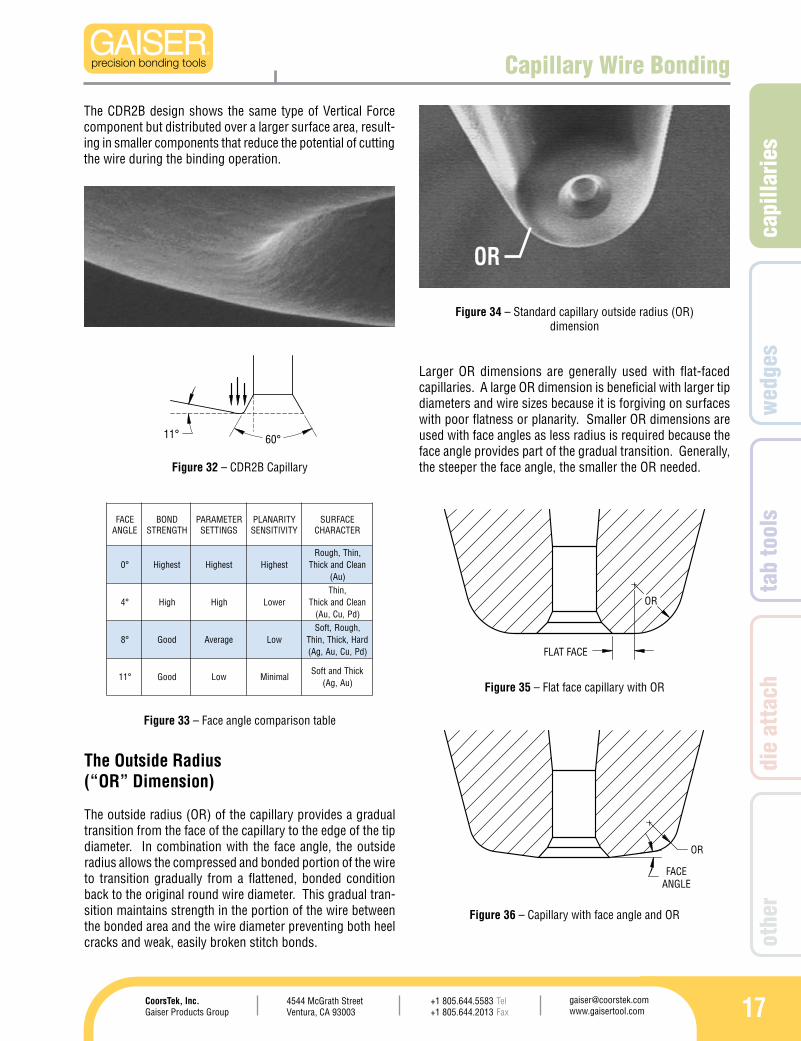
The impact of stresses during the second bond formation is an important subject in order to understand the mechanism behind it. Stresses applied to the wire during the formation of the second bond are responsible for the integrity and strength of that bond.
The following generic diagram illustrates the stress distribu-tion ocurring during the second bond formation.
Figure 31 – Standard capillary
Figure 30 – Compressive stress graph
capi
llarie
s
174544 McGrath StreetVentura, CA 93003
[email protected] www.gaisertool.com
CoorsTek, Inc.Gaiser Products Group
TelFax
+1 805.644.5583+1 805.644.2013
wed
ges
tab
tool
sdi
e at
tach
othe
r
OR
FLAT FACE
OR
FACE ANGLE
60°11°
ECAFELGNA
DNOBHTGNERTS
RETEMARAPSGNITTES
YTIRANALPYTIVITISNES
ECAFRUSRETCARAHC
°0 tsehgiH tsehgiH tsehgiH,nihT,hguoRnaelCdnakcihT
)uA(
°4 hgiH hgiH rewoL,nihT
naelCdnakcihT)dP,uC,uA(
°8 dooG egarevA woL,hguoR,tfoS
draH,kcihT,nihT)dP,uC,uA,gA(
°11 dooG woL laminiMkcihTdnatfoS
)uA,gA(
Capillary Wire Bonding
The Outside Radius(“OR” Dimension)
The outside radius (OR) of the capillary provides a gradual transition from the face of the capillary to the edge of the tip diameter. In combination with the face angle, the outside radius allows the compressed and bonded portion of the wire to transition gradually from a flattened, bonded condition back to the original round wire diameter. This gradual tran-sition maintains strength in the portion of the wire between the bonded area and the wire diameter preventing both heel cracks and weak, easily broken stitch bonds.
Figure 32 – CDR2B Capillary
Larger OR dimensions are generally used with flat-faced capillaries. A large OR dimension is beneficial with larger tip diameters and wire sizes because it is forgiving on surfaces with poor flatness or planarity. Smaller OR dimensions are used with face angles as less radius is required because the face angle provides part of the gradual transition. Generally, the steeper the face angle, the smaller the OR needed.
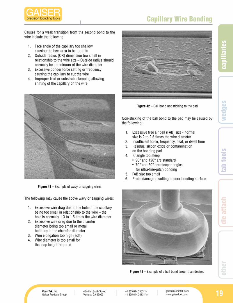
Figure 34 – Standard capillary outside radius (OR) dimension
Figure 33 – Face angle comparison table
The CDR2B design shows the same type of Vertical Force component but distributed over a larger surface area, result-ing in smaller components that reduce the potential of cutting the wire during the binding operation.
Figure 35 – Flat face capillary with OR
Figure 36 – Capillary with face angle and OR
OR
18
OR
GREATERTHAN TYPICAL
WIRE DIAMETER
Capillary Wire Bonding
For surfaces with poor flatness and/or planarity, the XX70 fea-tures an “oversize” outside radius design which is truncated by the tip diameter. This design provides a gradual transition similar to a face angle but does not become parallel to the bonding surface when the bonding surface is not flat.
Figure 37 – XX70 style OR capillary
In fine-pitch designs, both large OR’s with flat faces, and small OR’s with steep face angles, are used due to the similar transition effects on the stitch bond caused by very short 2nd-bond bond lengths. For more information about fine-pitch OR design, see the fine-pitch wire bonding section (see page 41).
Bonding Problems
Figure 40 – Example of a weak transition from the stitch bond to the wire
Figure 39 – Example of a non-sticking 2nd bond
Figure 38 – Example of a weak/ chopped-off or cut bond.
The reasons for non sticking bonds are as follows:
Poor plating or metal type of the substrate1. Contamination on the substrate material2. Lead or package not clamped rigidly causing the 3. lead to move resulting in poor ultrasonic energy transfer from the capillary to the wire and leadLead surface not planar to the capillary face4. Improper frequencies, force, time, or heat 5. settings – higher frequency transducer may be required for fine and ultra-fine-pitch applicationsCapillary T dimension may be too small 6. resulting in too short of a bond
The primary reasons for a weak/chopped-off or cut bond are:
Capillary T dimension is too small1. Inside chamfer area of the capillary is worn 2. away resulting in a shorter bond lengthExcessive metals build up on the face and 3. chamfer diameter area of the capillary
capi
llarie
s
194544 McGrath StreetVentura, CA 93003
[email protected] www.gaisertool.com
CoorsTek, Inc.Gaiser Products Group
TelFax
+1 805.644.5583+1 805.644.2013
wed
ges
tab
tool
sdi
e at
tach
othe
r
Capillary Wire Bonding
Figure 41 – Example of wavy or sagging wires
Figure 42 – Ball bond not sticking to the pad
Figure 43 – Example of a ball bond larger than desired
Causes for a weak transition from the second bond to the wire include the following:
Face angle of the capillary too shallow 1. causing the heel area to be too thinOutside radius (OR) dimension too small in 2. relationship to the wire size – Outside radius should normally be a minimum of the wire diameterExcessive bonder force setting or frequency 3. causing the capillary to cut the wireImproper lead or substrate clamping allowing 4. shifting of the capillary on the wire
The following may cause the above wavy or sagging wires:
Excessive wire drag due to the hole of the capillary 1. being too small in relationship to the wire – the hole is normally 1.3 to 1.5 times the wire diameterExcessive wire drag due to the chamfer 2. diameter being too small or metal build-up in the chamfer diameterWire elongation too high (soft)3. Wire diameter is too small for 4. the loop length required
Non-sticking of the ball bond to the pad may be caused by the following:
Excessive free air ball (FAB) size - normal 1. size is 2 to 2.5 times the wire diameterInsufficient force, frequency, heat, or dwell time2. Residual silicon oxide or contamination 3. on the bonding padIC angle too steep 4. •90°and120°arestandard •70°and50°aresteeperangles for ultra-fine-pitch bondingFAB size too small5. Probe damage resulting in poor bonding surface6.
20
Capillary Wire Bonding
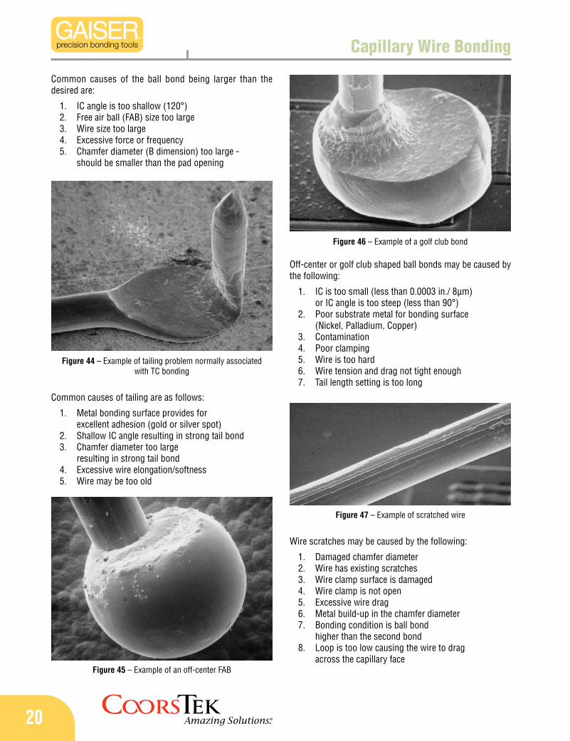
Figure 44 – Example of tailing problem normally associated with TC bonding
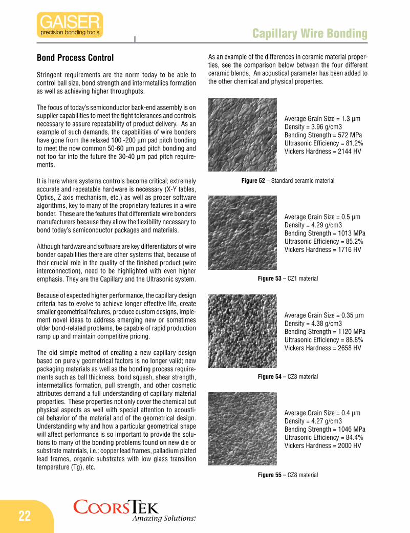
Figure 47 – Example of scratched wire
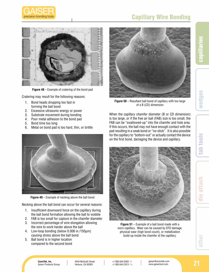
Figure 46 – Example of a golf club bond
Figure 45 – Example of an off-center FAB
Common causes of the ball bond being larger than the desired are:
IC angle is too shallow (120°)1. Free air ball (FAB) size too large2. Wire size too large3. Excessive force or frequency4. Chamfer diameter (B dimension) too large - 5. should be smaller than the pad opening
Common causes of tailing are as follows:
Metal bonding surface provides for 1. excellent adhesion (gold or silver spot)Shallow IC angle resulting in strong tail bond2. Chamfer diameter too large 3. resulting in strong tail bondExcessive wire elongation/softness4. Wire may be too old 5.
Off-center or golf club shaped ball bonds may be caused by the following:
IC is too small (less than 0.0003 in./ 8µm) 1. or IC angle is too steep (less than 90°)Poor substrate metal for bonding surface 2. (Nickel, Palladium, Copper)Contamination3. Poor clamping4. Wire is too hard5. Wire tension and drag not tight enough6. Tail length setting is too long 7.
Wire scratches may be caused by the following:
Damaged chamfer diameter1. Wire has existing scratches2. Wire clamp surface is damaged3. Wire clamp is not open4. Excessive wire drag5. Metal build-up in the chamfer diameter6. Bonding condition is ball bond 7. higher than the second bondLoop is too low causing the wire to drag 8. across the capillary face
capi
llarie
s
214544 McGrath StreetVentura, CA 93003
[email protected] www.gaisertool.com
CoorsTek, Inc.Gaiser Products Group
TelFax
+1 805.644.5583+1 805.644.2013
wed
ges
tab
tool
sdi
e at
tach
othe
r
Capillary Wire Bonding
Figure 48 – Example of cratering of the bond pad
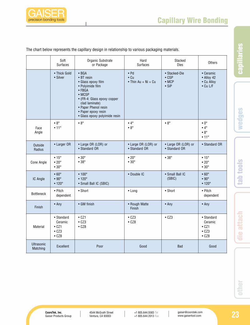
Figure 50 – Resultant ball bond of capillary with too large of a B (CD) dimension
Figure 51 – Example of a ball bond made with a worn capillary. Wear can be caused by EFO damage,
physical wear (high bond count), or metallization build-up inside the chamfer of the capillary.
Cratering may result for the following reasons:
Bond heads dropping too fast in 1. forming the ball bond Excessive ultrasonic energy or power2. Substrate movement during bonding3. Poor metal adhesion to the bond pad4. Bond time too long5. Metal on bond pad is too hard, thin, or brittle6.
Necking above the ball bond can occur for several reasons:
Insufficient downward force on the capillary during 1. the ball bond formation allowing the ball to wobble FAB is too small for capture in the chamfer diameter2. Incorrect percentage of wire elongation allowing 3. the wire to work harder above the ballLow-loop bonding (below 0.006 in./150µm) 4. causing stress above the ball bondBall bond is in higher location 5. compared to the second bond
When the capillary chamfer diameter (B or CD dimension) is too large, or if the free air ball (FAB) size is too small, the FAB can be “swallowed-up” into the chamfer and hole area. If this occurs, the ball may not have enough contact with the pad resulting in a weak bond or “no-stick”. It is also possible for the capillary to “bottom-out” or actually contact the device on the first bond, damaging the device and capillary.
Figure 49 – Example of necking above the ball bond
22
Capillary Wire Bonding
Bond Process Control
Stringent requirements are the norm today to be able to control ball size, bond strength and intermetallics formation as well as achieving higher throughputs.
The focus of today’s semiconductor back-end assembly is on supplier capabilities to meet the tight tolerances and controls necessary to assure repeatability of product delivery. As an example of such demands, the capabilities of wire bonders have gone from the relaxed 100 -200 µm pad pitch bonding to meet the now common 50-60 µm pad pitch bonding and not too far into the future the 30-40 µm pad pitch require-ments.
It is here where systems controls become critical; extremely accurate and repeatable hardware is necessary (X-Y tables, Optics, Z axis mechanism, etc.) as well as proper software algorithms, key to many of the proprietary features in a wire bonder. These are the features that differentiate wire bonders manufacturers because they allow the flexibility necessary to bond today’s semiconductor packages and materials.
Although hardware and software are key differentiators of wire bonder capabilities there are other systems that, because of their crucial role in the quality of the finished product (wire interconnection), need to be highlighted with even higher emphasis. They are the Capillary and the Ultrasonic system.
Because of expected higher performance, the capillary design criteria has to evolve to achieve longer effective life, create smaller geometrical features, produce custom designs, imple-ment novel ideas to address emerging new or sometimes older bond-related problems, be capable of rapid production ramp up and maintain competitive pricing.
The old simple method of creating a new capillary design based on purely geometrical factors is no longer valid; new packaging materials as well as the bonding process require-ments such as ball thickness, bond squash, shear strength, intermetallics formation, pull strength, and other cosmetic attributes demand a full understanding of capillary material properties. These properties not only cover the chemical but physical aspects as well with special attention to acousti-cal behavior of the material and of the geometrical design. Understanding why and how a particular geometrical shape will affect performance is so important to provide the solu-tions to many of the bonding problems found on new die or substrate materials, i.e.: copper lead frames, palladium plated lead frames, organic substrates with low glass transition temperature (Tg), etc.
Figure 52 – Standard ceramic material
Average Grain Size = 1.3 µmDensity = 3.96 g/cm3Bending Strength = 572 MPaUltrasonic Efficiency = 81.2%Vickers Hardness = 2144 HV
Average Grain Size = 0.5 µmDensity = 4.29 g/cm3Bending Strength = 1013 MPaUltrasonic Efficiency = 85.2%Vickers Hardness = 1716 HV
Figure 53 – CZ1 material
Figure 54 – CZ3 material
Figure 55 – CZ8 material
Average Grain Size = 0.35 µmDensity = 4.38 g/cm3Bending Strength = 1120 MPaUltrasonic Efficiency = 88.8%Vickers Hardness = 2658 HV
Average Grain Size = 0.4 µmDensity = 4.27 g/cm3Bending Strength = 1046 MPaUltrasonic Efficiency = 84.4%Vickers Hardness = 2000 HV
As an example of the differences in ceramic material proper-ties, see the comparison below between the four different ceramic blends. An acoustical parameter has been added to the other chemical and physical properties.
capi
llarie
s
234544 McGrath StreetVentura, CA 93003
[email protected] www.gaisertool.com
CoorsTek, Inc.Gaiser Products Group
TelFax
+1 805.644.5583+1 805.644.2013
wed
ges
tab
tool
sdi
e at
tach
othe
r
tfoSsecafruS
etartsbuScinagrOegakcaPro
draHsecafruS
dekcatSseiD srehtO
kcihT• dloGrevliS•
AGB•niserTB•
mlifyxopessalG•mlifedimiyloP•
AGBF•PSCM•
reppocyxopessalG:4-RF(•)etanimaldalc
niserlonehPrepaP•niseryxoperepaP•
niseredimiylopyxopessalG•
dP•uC•
uC+iN+uAnihT•
eiD-dekcatS•PSC•PCM•
PiS•
cimareC•24yollA•yollAuC•
F/LuC•
ecaFelgnA
°8•°11•
°8• °4•°8•
°8• °0•°4•°8•
°11•
edistuOsuidaR
ROregraL• ro)ROL(ROegraL•ROdradnatS•
ro)ROL(ROegraL•ROdradnatS•
ro)ROL(ROegraL•ROdradnatS•
ROdradnatS•
elgnAenoC°51•°02•°03•
°03•°83•
°02•°03•
°83• °51•°02•°03•
elgnACI°06•°09•
°021•
°001•°021•
)CIBS(CIllaBllamS•
CIelbuoD• CIllaBllamS•)CIBS(
°06•°09•
°021•
kcenelttoBhctiP•
tnednepedtrohS• gnoL• trohS• hctiP•
tnedneped
hsiniFynA• hsinifMG• ettaMhguoR•
hsiniFynA• ynA•
lairetaM
dradnatS•cimareC
1ZC•3ZC•8ZC•
1ZC•3ZC•8ZC•
3ZC•8ZC•
3ZC• dradnatS•cimareC
1ZC•3ZC•8ZC•
cinosartlUgnihctaM tnellecxE rooP dooG daB dooG
Capillary Wire Bonding
The chart below represents the capillary design in relationship to various packaging materials.
24
1513-18-437GM-20D-CZ1
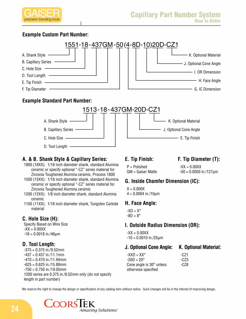
Capillary Part Number SystemHow to Order
A. & B. Shank Style & Capillary Series:1800 (18XX): 1/16 inch diameter shank, standard Alumina
ceramic or specify optional “-CZ” series material for Zirconia Toughened Alumina ceramic, Process 1800
1500 (15XX): 1/16 inch diameter shank, standard Alumina ceramic or specify optional “-CZ” series material for Zirconia Toughened Alumina ceramic
1200 (12XX): 1/8 inch diameter shank, standard Alumina ceramic
1100 (11XX): 1/16 inch diameter shank, Tungsten Carbide material
C. Hole Size (H):Specify Based on Wire Size-XX = 0.00XX-18 = 0.0018 in./46µm
D. Tool Length:-375 = 0.375 in./9.52mm-437 = 0.437 in./11.1mm-470 = 0.470 in./11.94mm-625 = 0.625 in./15.88mm-750 = 0.750 in./19.05mm1200 series are 0.375 in./9.52mm only (do not specify length in part number)
E. Tip Finish:
G. Inside Chamfer Dimension (IC):X = 0.000X4 = 0.0004 in./10µm
H. Face Angle:-XD = X°-8D = 8°
I. Outside Radius Dimension (OR):-XX = 0.00XX-10 = 0.0010 in./25µm
Example Custom Part Number:
J. Optional Cone Angle:-XXD = XX°-20D = 20°Cone angle is 30° unless otherwise specified
1551-18-437GM-50(4-8D-10)20D-CZ1
A. Shank Style
B. Capillary Series
C. Hole Size
D. Tool Length
E. Tip Finish
F. Tip Diameter
J. Optional Cone Angle
I. OR Dimension
H. Face Angle
G. IC Dimension
K. Optional Material
P = PolishedGM = Gaiser Matte
F. Tip Diameter (T):-XX = 0.00XX-50 = 0.0050 in./127µm
Example Standard Part Number:
A. Shank Style
B. Capillary Series
C. Hole Size
D. Tool Length
J. Optional Cone Angle
E. Tip Finish
K. Optional Material
K. Optional Material:-CZ1-CZ3-CZ8
We reserve the right to change the design or specification of any catalog item without notice. Such changes will be in the interest of improving design.
capi
llarie
s
254544 McGrath StreetVentura, CA 93003
[email protected] www.gaisertool.com
CoorsTek, Inc.Gaiser Products Group
TelFax
+1 805.644.5583+1 805.644.2013
wed
ges
tab
tool
sdi
e at
tach
othe
r
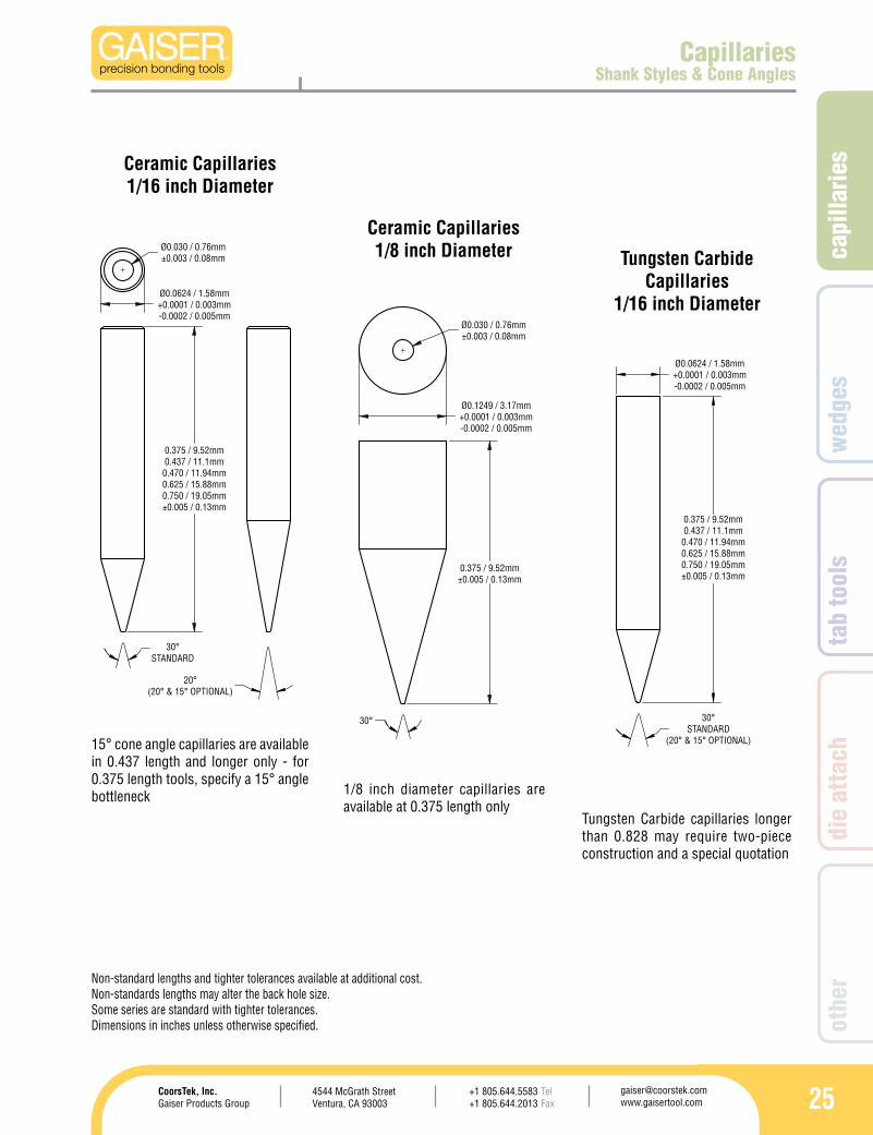
CapillariesShank Styles & Cone Angles
15° cone angle capillaries are available in 0.437 length and longer only - for 0.375 length tools, specify a 15° angle bottleneck
Non-standard lengths and tighter tolerances available at additional cost.Non-standards lengths may alter the back hole size.Some series are standard with tighter tolerances.Dimensions in inches unless otherwise specified.
Ceramic Capillaries1/16 inch Diameter
Ceramic Capillaries1/8 inch Diameter Tungsten Carbide
Capillaries1/16 inch Diameter
1/8 inch diameter capillaries are available at 0.375 length only
Tungsten Carbide capillaries longer than 0.828 may require two-piece construction and a special quotation
0.375 / 9.52mm0.437 / 11.1mm
0.470 / 11.94mm0.625 / 15.88mm0.750 / 19.05mm±0.005 / 0.13mm
20°(20° & 15° OPTIONAL)
Ø0.0624 / 1.58mm+0.0001 / 0.003mm-0.0002 / 0.005mm
Ø0.030 / 0.76mm±0.003 / 0.08mm
Ø0.1249 / 3.17mm+0.0001 / 0.003mm-0.0002 / 0.005mm
0.375 / 9.52mm±0.005 / 0.13mm
Ø0.030 / 0.76mm±0.003 / 0.08mm
0.375 / 9.52mm0.437 / 11.1mm0.470 / 11.94mm0.625 / 15.88mm0.750 / 19.05mm±0.005 / 0.13mm
Ø0.0624 / 1.58mm+0.0001 / 0.003mm-0.0002 / 0.005mm
30°STANDARD
(20° & 15° OPTIONAL)
30°STANDARD
30°
0.375 / 9.52mm0.437 / 11.1mm0.470 / 11.94mm0.625 / 15.88mm0.750 / 19.05mm±0.005 / 0.13mm
20°(20° & 15° OPTIONAL)
Ø0.0624 / 1.58mm+0.0001 / 0.003mm-0.0002 / 0.005mm
Ø0.030 / 0.76mm±0.003 / 0.08mm
Ø0.1249 / 3.17mm+0.0001 / 0.003mm-0.0002 / 0.005mm
0.375 / 9.52mm±0.005 / 0.13mm
Ø0.030 / 0.76mm±0.003 / 0.08mm
0.375 / 9.52mm0.437 / 11.1mm0.470 / 11.94mm0.625 / 15.88mm0.750 / 19.05mm±0.005 / 0.13mm
Ø0.0624 / 1.58mm+0.0001 / 0.003mm-0.0002 / 0.005mm
30°STANDARD
(20° & 15° OPTIONAL)
30°STANDARD
30°
26
HEIGHT+0.005-0.000
HEIGHT+0.005-0.000
10° 15°
HEIGHT+0.005-0.000
HEIGHT+0.005-0.000
D+0.0000-0.0005
D+0.0000-0.0005
10°
RADIUS
0.012
ELBATNGISEDKCENELTTOBTHGIARTS
BSD
ISNEMID NO/.ni mµ
MUMIXAMH
ISNEMID NOGNEL573.0 HT
/.ni mµ
MUMIXAMH
ISNEMID NOGNEL734.0 HT
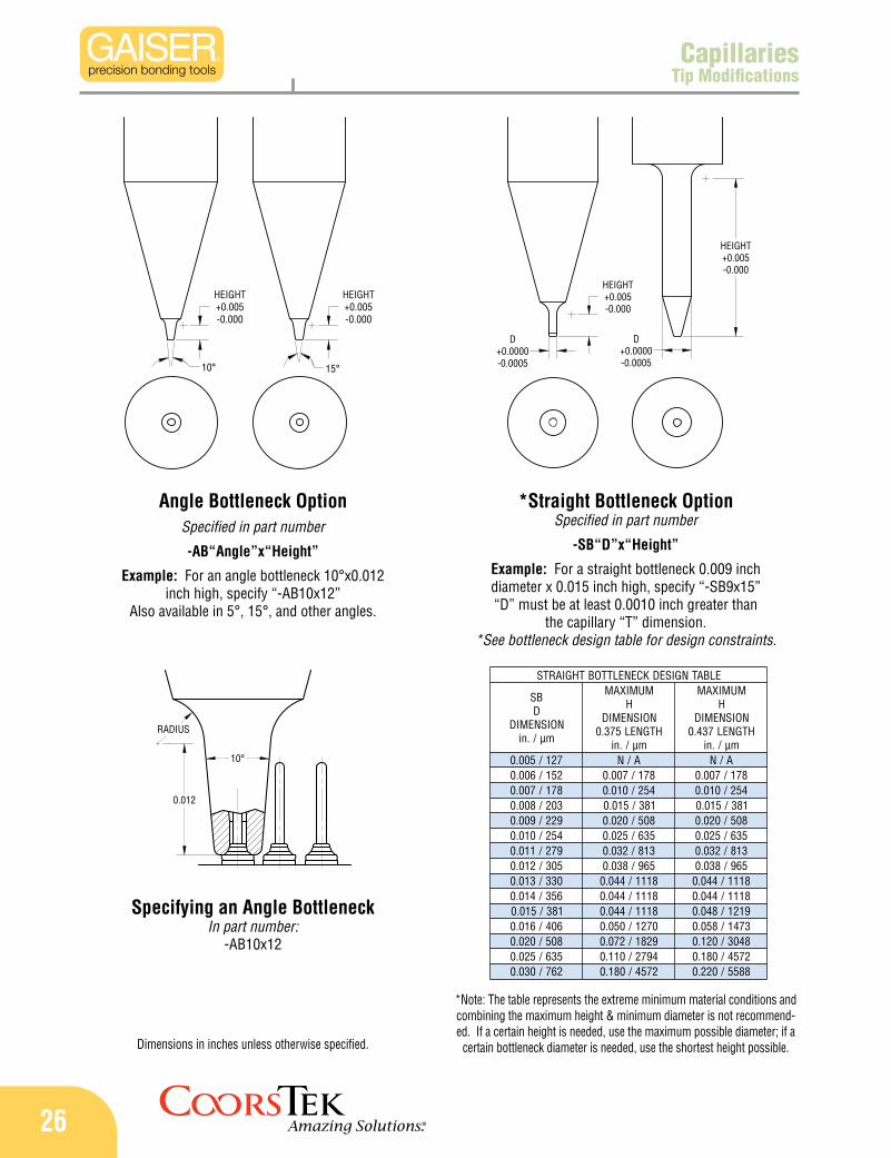
/.ni mµ721/500.0 A/N A/N251/600.0 871/700.0 871/700.0871/700.0 452/010.0 452/010.0302/800.0 183/510.0 183/510.0922/900.0 805/020.0 805/020.0452/010.0 536/520.0 536/520.0972/110.0 318/230.0 318/230.0503/210.0 569/830.0 569/830.0033/310.0 8111/440.0 8111/440.0653/410.0 8111/440.0 8111/440.0183/510.0 8111/440.0 9121/840.0604/610.0 0721/050.0 3741/850.0805/020.0 9281/270.0 8403/021.0536/520.0 4972/011.0 2754/081.0267/030.0 2754/081.0 8855/022.0
CapillariesTip Modifications
Dimensions in inches unless otherwise specified.
Angle Bottleneck OptionSpecified in part number
-AB“Angle”x“Height”
Example: For an angle bottleneck 10°x0.012 inch high, specify “-AB10x12”
Also available in 5°, 15°, and other angles.
*Straight Bottleneck Option Specified in part number
-SB“D”x“Height”
Example: For a straight bottleneck 0.009 inch diameter x 0.015 inch high, specify “-SB9x15” “D” must be at least 0.0010 inch greater than
the capillary “T” dimension.*See bottleneck design table for design constraints.
Specifying an Angle BottleneckIn part number:
-AB10x12
*Note: The table represents the extreme minimum material conditions and combining the maximum height & minimum diameter is not recommend-ed. If a certain height is needed, use the maximum possible diameter; if a
certain bottleneck diameter is needed, use the shortest height possible.
capi
llarie
s
274544 McGrath StreetVentura, CA 93003
[email protected] www.gaisertool.com
CoorsTek, Inc.Gaiser Products Group
TelFax
+1 805.644.5583+1 805.644.2013
wed
ges
tab
tool
sdi
e at
tach
othe
r
HEIGHT+0.005-0.000
HEIGHT+0.005-0.000
W+0.0000-0.0005
W+0.0000-0.0005
HEIGHT+0.005-0.000
W+0.0000-0.0005
0.065
0.015
HEIGHT=0.065
W=0.010
Clearance is user preference
ELBATNGISEDFEILEREDISELBUOD
NOITPORDW
NOISNEMIDmµ/.ni
MUMIXAMH
NOISNEMIDHTGNEL573.0
mµ/.ni
MUMIXAMH
NOISNEMIDHTGNEL734.0
mµ/.ni
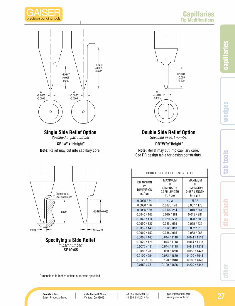
46/5200.0 A/N A/N67/0300.0 871/700.0 871/700.098/5300.0 452/010.0 452/010.0201/0400.0 183/510.0 183/510.0411/5400.0 805/020.0 805/020.0721/0500.0 536/520.0 536/520.0041/5500.0 318/230.0 318/230.0251/0600.0 569/830.0 569/830.0561/5600.0 8111/440.0 8111/440.0871/0700.0 8111/440.0 8111/440.0191/5700.0 8111/440.0 9121/840.0302/0800.0 0721/050.0 3741/850.0452/0010.0 9281/270.0 8403/021.0813/5210.0 8403/021.0 6284/091.0183/0510.0 6284/091.0 2485/032.0
CapillariesTip Modifications
Dimensions in inches unless otherwise specified.
Single Side Relief Option Specified in part number
-SR“W”x“Height”
Note: Relief may cut into capillary core.
Double Side Relief Option Specified in part number
-DR“W”x“Height”
Note: Relief may cut into capillary core. See DR design table for design constraints.
Specifying a Side ReliefIn part number:
-SR10x65
28
90°
IC
120°
OR
H
B
T
30°(STANDARD)
8°
1513
Capillaries1513 & 1513N Series
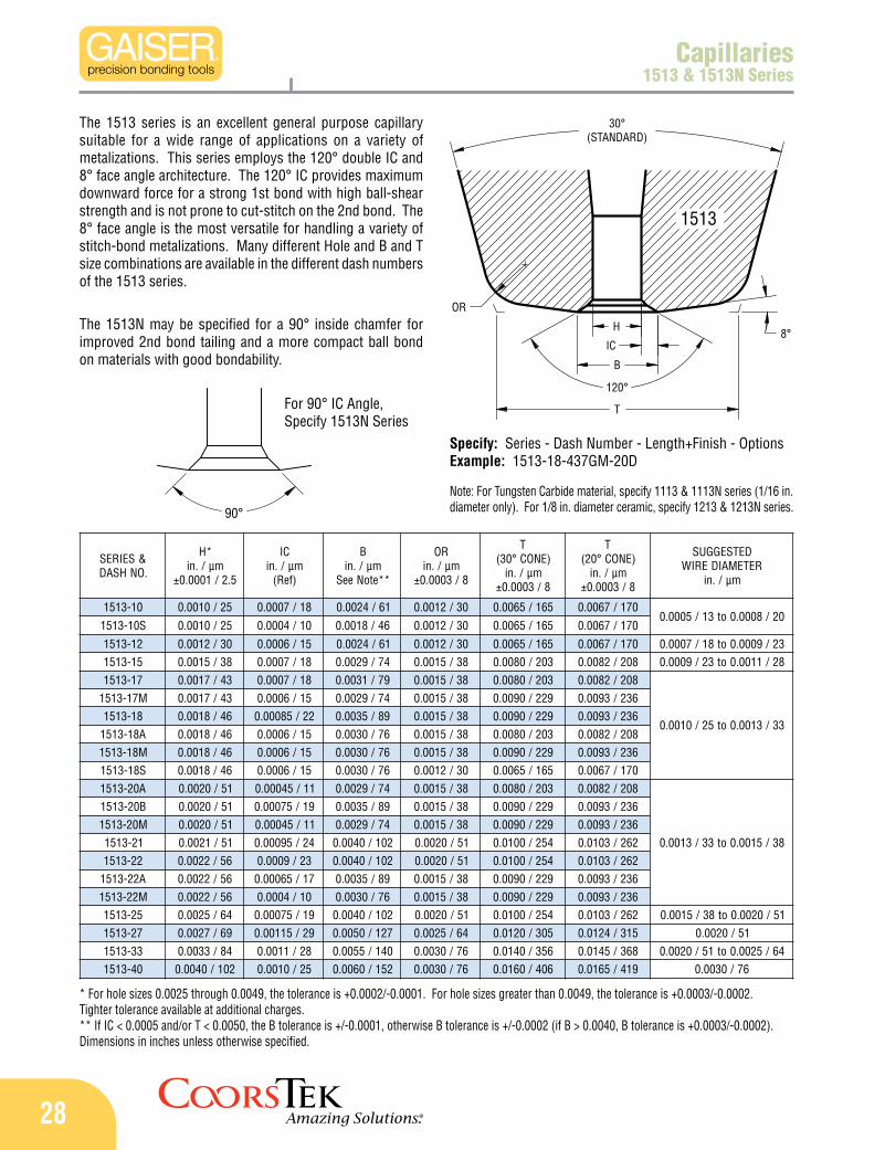
The 1513 series is an excellent general purpose capillary suitable for a wide range of applications on a variety of metalizations. This series employs the 120° double IC and 8° face angle architecture. The 120° IC provides maximum downward force for a strong 1st bond with high ball-shear strength and is not prone to cut-stitch on the 2nd bond. The 8° face angle is the most versatile for handling a variety of stitch-bond metalizations. Many different Hole and B and T size combinations are available in the different dash numbers of the 1513 series.
The 1513N may be specified for a 90° inside chamfer for improved 2nd bond tailing and a more compact ball bond on materials with good bondability.
* For hole sizes 0.0025 through 0.0049, the tolerance is +0.0002/-0.0001. For hole sizes greater than 0.0049, the tolerance is +0.0003/-0.0002. Tighter tolerance available at additional charges.** If IC < 0.0005 and/or T < 0.0050, the B tolerance is +/-0.0001, otherwise B tolerance is +/-0.0002 (if B > 0.0040, B tolerance is +0.0003/-0.0002).Dimensions in inches unless otherwise specified.
Note: For Tungsten Carbide material, specify 1113 & 1113N series (1/16 in. diameter only). For 1/8 in. diameter ceramic, specify 1213 & 1213N series.
For 90° IC Angle, Specify 1513N Series
Specify: Series - Dash Number - Length+Finish - OptionsExample: 1513-18-437GM-20D
&SEIRES.ONHSAD
*Hmµ/.ni
5.2/1000.0±
CImµ/.ni)feR(
Bmµ/.ni
**etoNeeS
ROmµ/.ni
8/3000.0±
T)ENOC°03(
mµ/.ni8/3000.0±
T)ENOC°02(
mµ/.ni8/3000.0±
DETSEGGUSRETEMAIDERIW
mµ/.ni
01-3151 52/0100.0 81/7000.0 16/4200.0 03/2100.0 561/5600.0 071/7600.002/8000.0ot31/5000.0
S01-3151 52/0100.0 01/4000.0 64/8100.0 03/2100.0 561/5600.0 071/7600.0
21-3151 03/2100.0 51/6000.0 16/4200.0 03/2100.0 561/5600.0 071/7600.0 32/9000.0ot81/7000.051-3151 83/5100.0 81/7000.0 47/9200.0 83/5100.0 302/0800.0 802/2800.0 82/1100.0ot32/9000.071-3151 34/7100.0 81/7000.0 97/1300.0 83/5100.0 302/0800.0 802/2800.0
33/3100.0ot52/0100.0
M71-3151 34/7100.0 51/6000.0 47/9200.0 83/5100.0 922/0900.0 632/3900.081-3151 64/8100.0 22/58000.0 98/5300.0 83/5100.0 922/0900.0 632/3900.0A81-3151 64/8100.0 51/6000.0 67/0300.0 83/5100.0 302/0800.0 802/2800.0M81-3151 64/8100.0 51/6000.0 67/0300.0 83/5100.0 922/0900.0 632/3900.0S81-3151 64/8100.0 51/6000.0 67/0300.0 03/2100.0 561/5600.0 071/7600.0A02-3151 15/0200.0 11/54000.0 47/9200.0 83/5100.0 302/0800.0 802/2800.0
83/5100.0ot33/3100.0
B02-3151 15/0200.0 91/57000.0 98/5300.0 83/5100.0 922/0900.0 632/3900.0M02-3151 15/0200.0 11/54000.0 47/9200.0 83/5100.0 922/0900.0 632/3900.012-3151 15/1200.0 42/59000.0 201/0400.0 15/0200.0 452/0010.0 262/3010.022-3151 65/2200.0 32/9000.0 201/0400.0 15/0200.0 452/0010.0 262/3010.0A22-3151 65/2200.0 71/56000.0 98/5300.0 83/5100.0 922/0900.0 632/3900.0M22-3151 65/2200.0 01/4000.0 67/0300.0 83/5100.0 922/0900.0 632/3900.052-3151 46/5200.0 91/57000.0 201/0400.0 15/0200.0 452/0010.0 262/3010.0 15/0200.0ot83/5100.072-3151 96/7200.0 92/51100.0 721/0500.0 46/5200.0 503/0210.0 513/4210.0 15/0200.033-3151 48/3300.0 82/1100.0 041/5500.0 67/0300.0 653/0410.0 863/5410.0 46/5200.0ot15/0200.004-3151 201/0400.0 52/0100.0 251/0600.0 67/0300.0 604/0610.0 914/5610.0 67/0300.0
capi
llarie
s
294544 McGrath StreetVentura, CA 93003
[email protected] www.gaisertool.com
CoorsTek, Inc.Gaiser Products Group
TelFax
+1 805.644.5583+1 805.644.2013
wed
ges
tab
tool
sdi
e at
tach
othe
r
90°
IC
OR
120°
H
B
T
30°(STANDARD)
8°
1572
&SEIRES.ONHSAD
*Hmµ/.ni
5.2/1000.0±
CImµ/.ni)feR(
Bmµ/.ni
**etoNeeS
ROmµ/.ni
8/3000.0±
T)ENOC°03(
mµ/.ni8/3000.0±
T)ENOC°02(
mµ/.ni8/3000.0±
DETSEGGUSRETEMAIDERIW
mµ/.ni
01-2751 52/0100.0 81/7000.0 16/4200.0 02/8000.0 041/5500.0 241/6500.002/8000.0ot31/5000.0
S01-2751 52/0100.0 01/4000.0 64/8100.0 02/8000.0 041/5500.0 241/6500.0
21-2751 03/2100.0 51/6000.0 16/4200.0 02/8000.0 041/5500.0 241/6500.0 32/9000.0ot81/7000.031-2751 33/3100.0 51/6000.0 46/5200.0 02/8000.0 041/5500.0 241/6500.0
52/0100.0ot02/8000.0S31-2751 33/3100.0 01/4000.0 35/1200.0 02/8000.0 041/5500.0 241/6500.051-2751 83/5100.0 81/7000.0 47/9200.0 52/0100.0 561/5600.0 071/7600.0
82/1100.0ot32/9000.0S51-2751 83/5100.0 51/6000.0 96/7200.0 02/8000.0 041/5500.0 241/6500.071-2751 34/7100.0 51/6000.0 47/9200.0 52/0100.0 922/0900.0 432/2900.0
33/3100.0ot52/0100.0S71-2751 34/7100.0 51/6000.0 47/9200.0 52/0100.0 561/5600.0 071/7600.081-2751 64/8100.0 51/6000.0 67/0300.0 52/0100.0 922/0900.0 432/2900.002-2751 15/0200.0 52/0100.0 201/0400.0 83/5100.0 922/0900.0 632/3900.0
83/5100.0ot33/3100.022-2751 65/2200.0 32/9000.0 201/0400.0 83/5100.0 922/0900.0 632/3900.052-2751 46/5200.0 33/3100.0 031/1500.0 15/0200.0 292/5110.0 003/8110.0 15/0200.0ot83/5100.003-2751 67/0300.0 33/3100.0 241/6500.0 46/5200.0 033/0310.0 043/4310.0 15/0200.053-2751 98/5300.0 52/0100.0 041/5500.0 67/0300.0 653/0410.0 863/5410.0 46/5200.0ot15/0200.004-2751 201/0400.0 52/0100.0 251/0600.0 67/0300.0 653/0410.0 863/5410.0 67/0300.005-2751 721/0500.0 33/3100.0 391/6700.0 67/0300.0 604/0610.0 914/5610.0 201/0400.007-2751 871/0700.0 83/5100.0 452/0010.0 721/0500.0 117/0820.0 237/8820.0 721/0500.0001-2751 452/0010.0 15/0200.0 653/0410.0 871/0700.0 569/0830.0 399/1930.0 251/0600.0
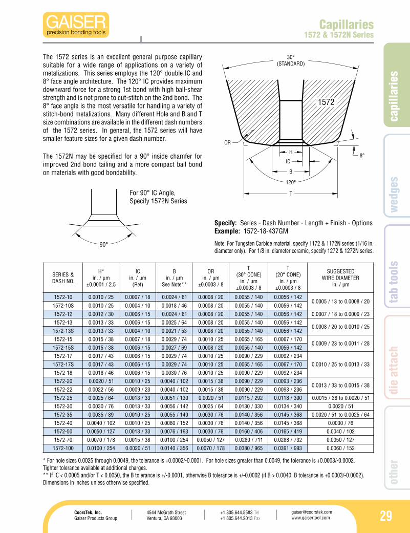
Capillaries1572 & 1572N Series
The 1572 series is an excellent general purpose capillary suitable for a wide range of applications on a variety of metalizations. This series employs the 120° double IC and 8° face angle architecture. The 120° IC provides maximum downward force for a strong 1st bond with high ball-shear strength and is not prone to cut-stitch on the 2nd bond. The 8° face angle is the most versatile for handling a variety of stitch-bond metalizations. Many different Hole and B and T size combinations are available in the different dash numbers of the 1572 series. In general, the 1572 series will have smaller feature sizes for a given dash number.
The 1572N may be specified for a 90° inside chamfer for improved 2nd bond tailing and a more compact ball bond on materials with good bondability.
Note: For Tungsten Carbide material, specify 1172 & 1172N series (1/16 in. diameter only). For 1/8 in. diameter ceramic, specify 1272 & 1272N series.
Specify: Series - Dash Number - Length + Finish - OptionsExample: 1572-18-437GM
* For hole sizes 0.0025 through 0.0049, the tolerance is +0.0002/-0.0001. For hole sizes greater than 0.0049, the tolerance is +0.0003/-0.0002. Tighter tolerance available at additional charges.** If IC < 0.0005 and/or T < 0.0050, the B tolerance is +/-0.0001, otherwise B tolerance is +/-0.0002 (if B > 0.0040, B tolerance is +0.0003/-0.0002).Dimensions in inches unless otherwise specified.
For 90° IC Angle, Specify 1572N Series
30
120°
IC
OR
30°(STANDARD)
H
B
T
90°
1570
&SEIRES.ONHSAD
*Hmµ/.ni
5.2/1000.0±
CImµ/.ni)feR(
Bmµ/.ni
**etoNeeS
***ROmµ/.ni
8/3000.0±
T)ENOC°03(
mµ/.ni8/3000.0±
T)ENOC°02(
mµ/.ni8/3000.0±
DETSEGGUSRETEMAIDERIW
mµ/.ni
01-0751 52/0100.0 8/3000.0 14/6100.0 15/0200.0 721/0500.0 031/1500.0 02/8000.0ot31/5000.021-0751 03/2100.0 8/3000.0 64/8100.0 15/0200.0 721/0500.0 031/1500.0 32/9000.0ot81/7000.031-0751 33/3100.0 01/4000.0 35/1200.0 46/5200.0 251/0600.0 751/2600.0 52/0100.0ot02/8000.051-0751 83/5100.0 31/5000.0 46/5200.0 67/0300.0 871/0700.0 381/2700.0 82/1100.0ot32/9000.071-0751 34/7100.0 51/6000.0 47/9200.0 98/5300.0 302/0800.0 112/3800.0
33/3100.0ot52/0100.081-0751 64/8100.0 51/6000.0 67/0300.0 98/5300.0 302/0800.0 112/3800.002-0751 15/0200.0 81/7000.0 68/4300.0 201/0400.0 922/0900.0 632/3900.0
83/5100.0ot33/3100.022-0751 65/2200.0 81/7000.0 19/6300.0 201/0400.0 922/0900.0 632/3900.052-0751 46/5200.0 02/8000.0 401/1400.0 721/0500.0 292/5110.0 203/9110.0 15/0200.0ot83/5100.003-0751 67/0300.0 32/9000.0 221/8400.0 251/0600.0 653/0410.0 663/4410.0
15/0200.053-0751 98/5300.0 82/1100.0 541/7500.0 871/0700.0 914/5610.0 234/0710.004-0751 201/0400.0 33/3100.0 861/6600.0 302/0800.0 384/0910.0 894/6910.0
67/0300.054-0751 411/5400.0 63/4100.0 581/3700.0 922/0900.0 635/1120.0 455/8120.005-0751 721/0500.0 83/5100.0 302/0800.0 452/0010.0 016/0420.0 726/7420.0 201/0400.006-0751 251/0600.0 64/8100.0 442/6900.0 503/0210.0 737/0920.0 957/9920.0
721/0500.007-0751 871/0700.0 35/1200.0 482/2110.0 653/0410.0 988/0530.0 419/0630.0
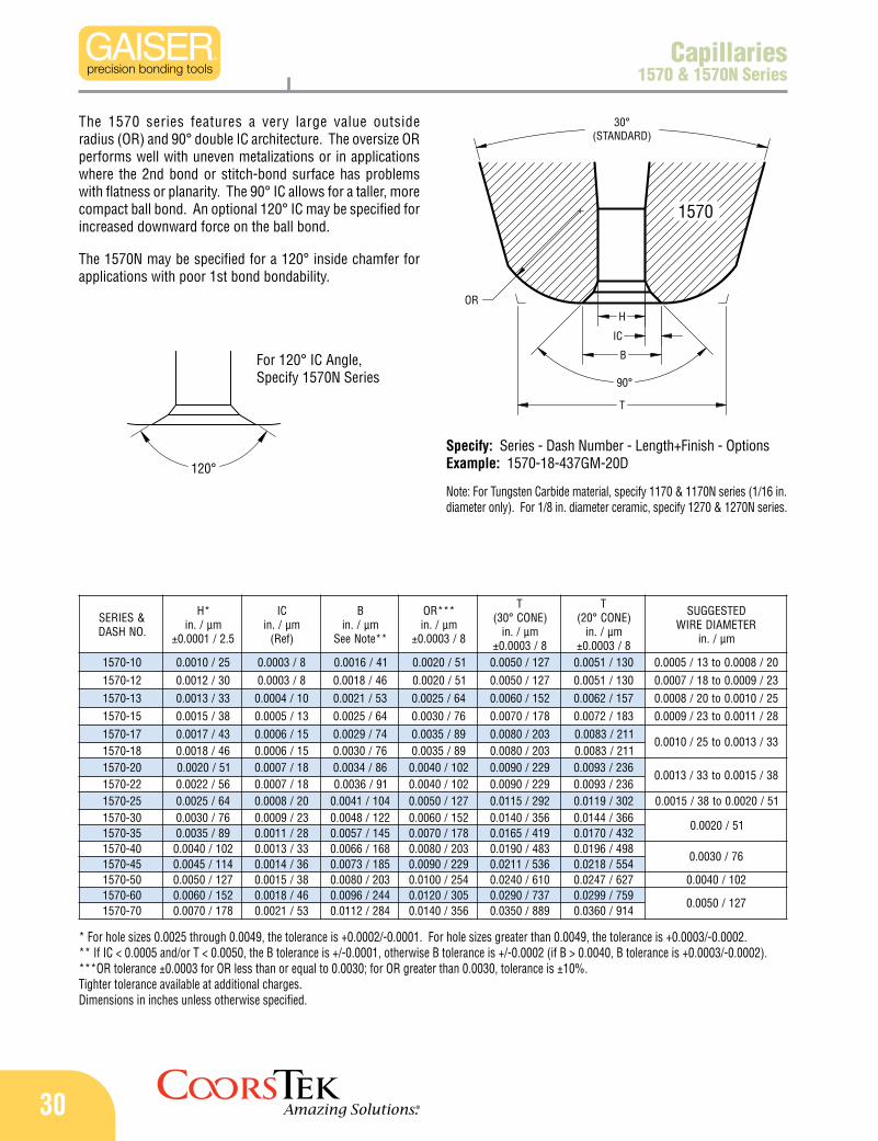
Capillaries1570 & 1570N Series
The 1570 series features a very large value outside radius (OR) and 90° double IC architecture. The oversize OR performs well with uneven metalizations or in applications where the 2nd bond or stitch-bond surface has problems with flatness or planarity. The 90° IC allows for a taller, more compact ball bond. An optional 120° IC may be specified for increased downward force on the ball bond.
The 1570N may be specified for a 120° inside chamfer for applications with poor 1st bond bondability.
Note: For Tungsten Carbide material, specify 1170 & 1170N series (1/16 in. diameter only). For 1/8 in. diameter ceramic, specify 1270 & 1270N series.
For 120° IC Angle, Specify 1570N Series
Specify: Series - Dash Number - Length+Finish - OptionsExample: 1570-18-437GM-20D
* For hole sizes 0.0025 through 0.0049, the tolerance is +0.0002/-0.0001. For hole sizes greater than 0.0049, the tolerance is +0.0003/-0.0002.** If IC < 0.0005 and/or T < 0.0050, the B tolerance is +/-0.0001, otherwise B tolerance is +/-0.0002 (if B > 0.0040, B tolerance is +0.0003/-0.0002). ***OR tolerance ±0.0003 for OR less than or equal to 0.0030; for OR greater than 0.0030, tolerance is ±10%.Tighter tolerance available at additional charges.Dimensions in inches unless otherwise specified.
capi
llarie
s
314544 McGrath StreetVentura, CA 93003
[email protected] www.gaisertool.com
CoorsTek, Inc.Gaiser Products Group
TelFax
+1 805.644.5583+1 805.644.2013
wed
ges
tab
tool
sdi
e at
tach
othe
r
120°
IC
OR
30°(STANDARD)
90°
B
T
H
1574
&SEIRES.ONHSAD
*Hmµ/.ni
5.2/1000.0±
CImµ/.ni)feR(
Bmµ/.ni
**etoNeeS
***ROmµ/.ni
8/3000.0±
T)ENOC°03(
mµ/.ni8/3000.0±
T)ENOC°02(
mµ/.ni8/3000.0±
DETSEGGUSRETEMAIDERIW
mµ/.ni
01-4751 52/0100.0 5/2000.0 63/4100.0 46/5200.0 561/5600.0 471/8600.0 02/8000.0ot31/5000.021-4751 03/2100.0 5/2000.0 14/6100.0 46/5200.0 561/5600.0 471/8600.0 32/9000.0ot81/7000.031-4751 33/3100.0 8/3000.0 84/9100.0 46/5200.0 561/5600.0 471/8600.0 52/0100.0ot02/8000.0S51-4751 83/5100.0 8/3000.0 35/1200.0 98/5300.0 302/0800.0 612/5800.0 82/1100.0ot32/9000.071-4751 34/7100.0 81/7000.0 97/1300.0 16/4200.0 302/0800.0 112/3800.0
33/31000.ot52/0100.0S71-4751 34/7100.0 5/2000.0 35/1200.0 98/5300.0 302/0800.0 612/5800.081-4751 64/8100.0 02/8000.0 68/4300.0 16/4200.0 302/0800.0 112/3800.0M81-4751 64/8100.0 41/55000.0 47/9200.0 16/4200.0 302/0800.0 112/3800.0S81-4751 64/8100.0 5/2000.0 65/2200.0 98/5300.0 302/0800.0 612/5800.002-4751 15/0200.0 81/7000.0 68/4300.0 16/4200.0 302/0800.0 112/3800.0
83/5100.0ot33/3100.0M02-4751 15/0200.0 11/54000.0 47/9200.0 16/4200.0 302/0800.0 112/3800.022-4751 65/2200.0 51/6000.0 68/4300.0 16/4200.0 302/0800.0 112/3800.0M22-4751 65/2200.0 9/53000.0 47/9200.0 16/4200.0 302/0800.0 112/3800.052-4751 46/5200.0 31/5000.0 98/5300.0 16/4200.0 302/0800.0 112/3800.0 15/0200.0ot83/5100.003-4751 67/0300.0 52/0100.0 721/0500.0 041/5500.0 914/5610.0 734/2710.0 15/0200.053-4751 98/5300.0 02/8000.0 031/1500.0 561/5600.0 914/5610.0 244/4710.0
46/5200.0ot15/0200.0S53-4751 98/5300.0 02/8000.0 031/1500.0 041/5500.0 914/5610.0 734/2710.004-4751 201/0400.0 52/0100.0 251/0600.0 561/5600.0 914/5610.0 244/4710.0 67/0300.005-4751 721/0500.0 03/2100.0 881/4700.0 871/0700.0 384/0910.0 805/0020.0 201/0400.0
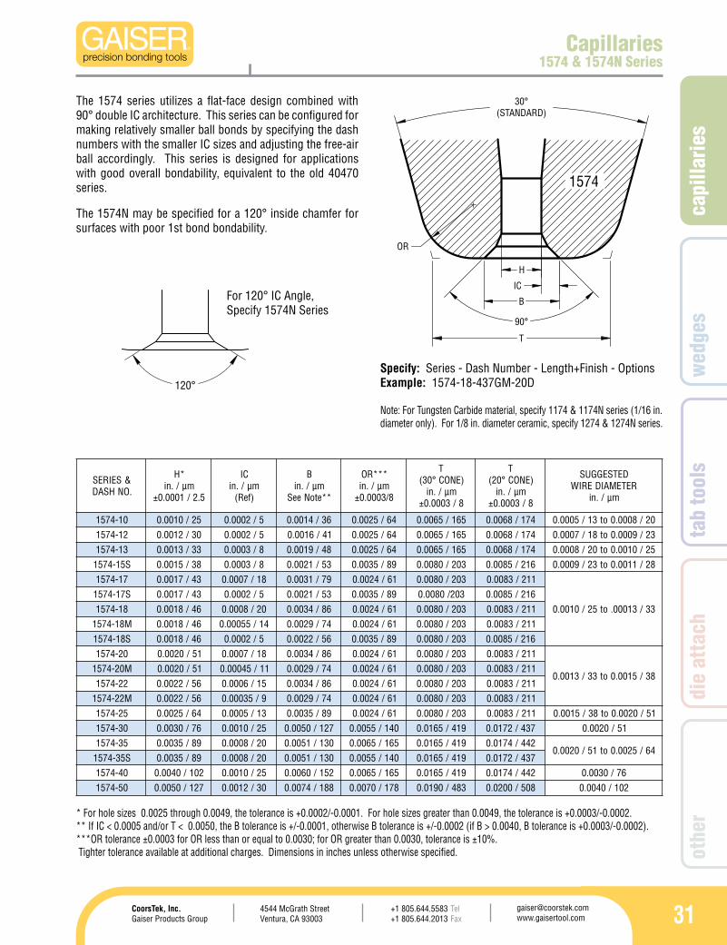
Capillaries1574 & 1574N Series
Note: For Tungsten Carbide material, specify 1174 & 1174N series (1/16 in. diameter only). For 1/8 in. diameter ceramic, specify 1274 & 1274N series.
The 1574 series utilizes a flat-face design combined with 90° double IC architecture. This series can be configured for making relatively smaller ball bonds by specifying the dash numbers with the smaller IC sizes and adjusting the free-air ball accordingly. This series is designed for applications with good overall bondability, equivalent to the old 40470 series.
The 1574N may be specified for a 120° inside chamfer for surfaces with poor 1st bond bondability.
For 120° IC Angle, Specify 1574N Series
Specify: Series - Dash Number - Length+Finish - OptionsExample: 1574-18-437GM-20D
* For hole sizes 0.0025 through 0.0049, the tolerance is +0.0002/-0.0001. For hole sizes greater than 0.0049, the tolerance is +0.0003/-0.0002.** If IC < 0.0005 and/or T < 0.0050, the B tolerance is +/-0.0001, otherwise B tolerance is +/-0.0002 (if B > 0.0040, B tolerance is +0.0003/-0.0002). ***OR tolerance ±0.0003 for OR less than or equal to 0.0030; for OR greater than 0.0030, tolerance is ±10%. Tighter tolerance available at additional charges. Dimensions in inches unless otherwise specified.
32
120°
IC
OR
30°(STANDARD)
90°
H
B
T
1548
&SEIRES.ONHSAD
*Hmµ/.ni
5.2/1000.0±
CImµ/.ni)feR(
Bmµ/.ni
**etoNeeS
***ROmµ/.ni
8/3000.0±
T)ENOC°03(
mµ/.ni8/3000.0±
T)ENOC°02(
mµ/.ni8/3000.0±
DETSEGGUSRETEMAIDERIW
mµ/.ni
01-8451 52/0100.0 01/4000.0 4/8100.0 6 64/8100.0 721/0500.0 231/2500.0 02/8000.0ot31/5000.021-8451 03/2100.0 9/53000.0 84/9100.0 64/8100.0 721/0500.0 231/2500.0 32/9000.0ot81/7000.031-8451 33/3100.0 01/4000.0 35/1200.0 35/1200.0 251/0600.0 061/3600.0 52/0100.0ot02/8000.051-8451 83/5100.0 31/5000.0 46/5200.0 46/5200.0 871/0700.0 581/3700.0 82/1100.0ot32/9000.071-8451 34/7100.0 51/6000.0 47/9200.0 47/9200.0 302/0800.0 312/4800.0
33/3100.0ot52/0100.081-8451 64/8100.0 71/56000.0 97/1300.0 47/9200.0 302/0800.0 312/4800.002-8451 15/0200.0 81/7000.0 68/4300.0 18/2300.0 922/0900.0 932/4900.0
83/5100.0ot33/3100.022-8451 65/2200.0 81/7000.0 19/6300.0 18/2300.0 922/0900.0 932/4900.003-8451 67/0300.0 32/9000.0 221/8400.0 221/8400.0 653/0410.0 373/7410.0 51/02000.53-8451 98/5300.0 32/9000.0 531/3500.0 561/5600.0 914/5610.0 244/4710.0 46/5200.0ot15/0200.004-8451 201/0400.0 23/52100.0 561/5600.0 561/5600.0 074/5810.0 394/4910.0 67/0300.0
Capillaries1548 & 1548N Series
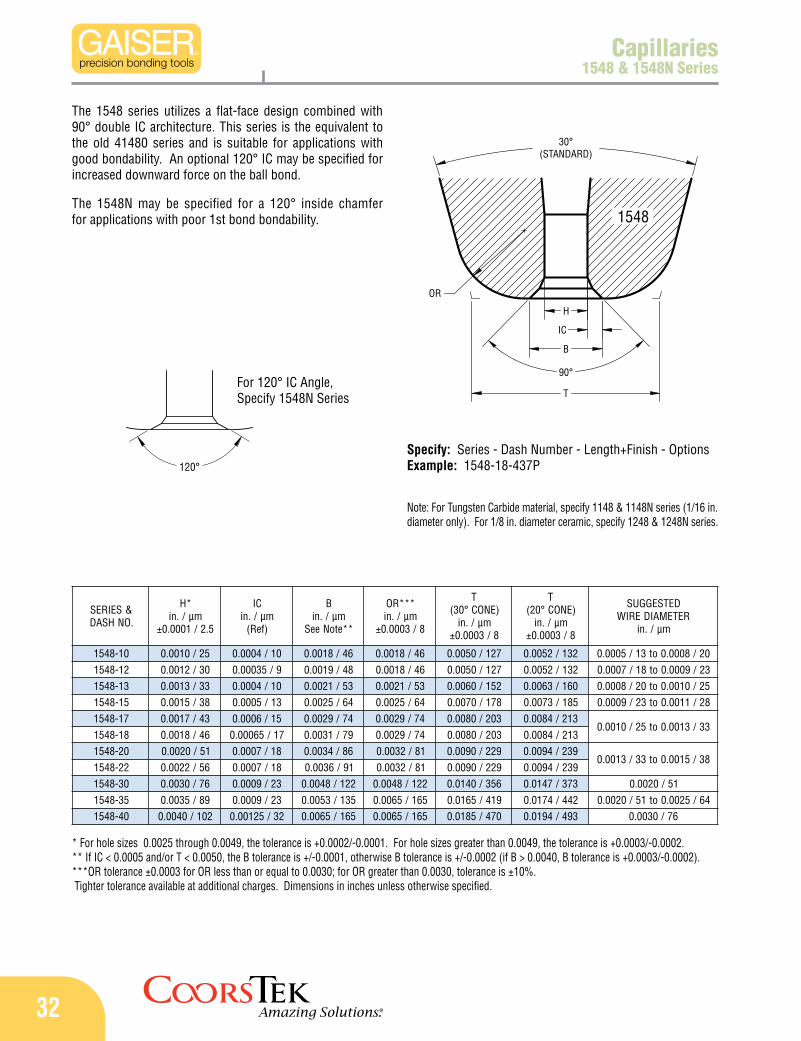
The 1548 series utilizes a flat-face design combined with 90° double IC architecture. This series is the equivalent to the old 41480 series and is suitable for applications with good bondability. An optional 120° IC may be specified for increased downward force on the ball bond.
The 1548N may be specified for a 120° inside chamfer for applications with poor 1st bond bondability.
Note: For Tungsten Carbide material, specify 1148 & 1148N series (1/16 in. diameter only). For 1/8 in. diameter ceramic, specify 1248 & 1248N series.
For 120° IC Angle, Specify 1548N Series
Specify: Series - Dash Number - Length+Finish - OptionsExample: 1548-18-437P
* For hole sizes 0.0025 through 0.0049, the tolerance is +0.0002/-0.0001. For hole sizes greater than 0.0049, the tolerance is +0.0003/-0.0002.** If IC < 0.0005 and/or T < 0.0050, the B tolerance is +/-0.0001, otherwise B tolerance is +/-0.0002 (if B > 0.0040, B tolerance is +0.0003/-0.0002). ***OR tolerance ±0.0003 for OR less than or equal to 0.0030; for OR greater than 0.0030, tolerance is ±10%. Tighter tolerance available at additional charges. Dimensions in inches unless otherwise specified.
capi
llarie
s
334544 McGrath StreetVentura, CA 93003
[email protected] www.gaisertool.com
CoorsTek, Inc.Gaiser Products Group
TelFax
+1 805.644.5583+1 805.644.2013
wed
ges
tab
tool
sdi
e at
tach
othe
r
90°
30°(STANDARD)
120°
T
8°H
IC
OR
B
IR
1573
&SEIRES.ONHSAD
*Hmµ/.ni
5.2/1000.0±
RImµ/.ni)feR(
Bmµ/.ni
**etoNeeS
***ROmµ/.ni
8/3000.0±
T)ENOC°03(
mµ/.ni8/3000.0±
T)ENOC°02(
mµ/.ni8/3000.0±
DETSEGGUSRETEMAIDERIW
mµ/.ni
11-3751 82/1100.0 01/4000.0 4/9100.0 8 02/8000.0 731/4500.0 041/5500.0 02/8000.0ot31/5000.0
21-3751 03/2100.0 01/4000.0 15/0200.0 02/8000.0 731/4500.0 041/5500.0 32/9000.0ot81/7000.031-3751 33/3100.0 01/4000.0 35/1200.0 02/8000.0 731/4500.0 041/5500.0
52/0100.0ot02/8000.041-3751 63/4100.0 01/4000.0 65/2200.0 02/8000.0 731/4500.0 041/5500.051-3751 83/5100.0 01/4000.0 85/3200.0 02/8000.0 731/4500.0 041/5500.0 82/1100.0ot32/9000.0
71-3751 34/7100.0 01/4000.0 46/5200.0 02/8000.0 741/8500.0 051/9500.033/3100.0ot52/0100.0
81-3751 64/8100.0 01/4000.0 66/6200.0 02/8000.0 741/8500.0 051/9500.0
91-3751 84/9100.0 51/6000.0 97/1300.0 52/0100.0 061/3600.0 561/5600.0 33/3100.0ot82/1100.012-3751 35/1200.0 51/6000.0 38/3300.0 52/0100.0 061/3600.0 561/5600.0
83/5100.0ot33/3100.022-3751 65/2200.0 51/6000.0 68/4300.0 52/0100.0 061/3600.0 561/5600.0
Capillaries1573 & 1573N Series
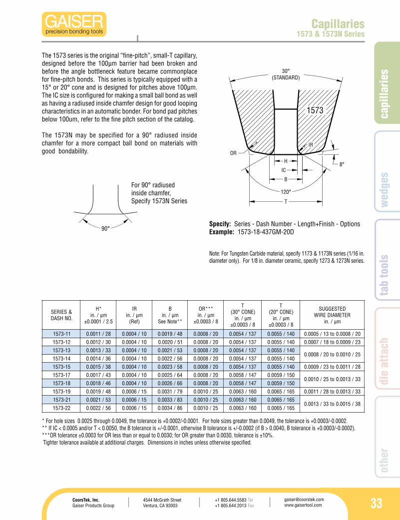
The 1573 series is the original “fine-pitch”, small-T capillary, designed before the 100µm barrier had been broken and before the angle bottleneck feature became commonplace for fine-pitch bonds. This series is typically equipped with a 15° or 20° cone and is designed for pitches above 100µm. The IC size is configured for making a small ball bond as well as having a radiused inside chamfer design for good looping characteristics in an automatic bonder. For bond pad pitches below 100um, refer to the fine pitch section of the catalog.
The 1573N may be specified for a 90° radiused inside chamfer for a more compact ball bond on materials with good bondability.
* For hole sizes 0.0025 through 0.0049, the tolerance is +0.0002/-0.0001. For hole sizes greater than 0.0049, the tolerance is +0.0003/-0.0002.** If IC < 0.0005 and/or T < 0.0050, the B tolerance is +/-0.0001, otherwise B tolerance is +/-0.0002 (if B > 0.0040, B tolerance is +0.0003/-0.0002). ***OR tolerance ±0.0003 for OR less than or equal to 0.0030; for OR greater than 0.0030, tolerance is ±10%. Tighter tolerance available at additional charges. Dimensions in inches unless otherwise specified.
Note: For Tungsten Carbide material, specify 1173 & 1173N series (1/16 in. diameter only). For 1/8 in. diameter ceramic, specify 1273 & 1273N series.
For 90° radiused inside chamfer, Specify 1573N Series
Specify: Series - Dash Number - Length+Finish - OptionsExample: 1573-18-437GM-20D
34
120°
IC
30°(STANDARD)
120°
FACEANGLE
OR
H
B
T
IR
1520
30°(STANDARD)
FACEANGLE
90°
OR
T
H
IC
B
1551
Custom User-Specified Dimensions Series1551, 1520, 1553, & 1554 Series
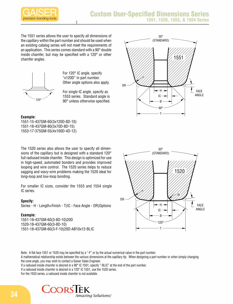
The 1551 series allows the user to specify all dimensions of the capillary within the part number and should be used when an existing catalog series will not meet the requirements of an application. This series comes standard with a 90° double inside chamfer, but may be specified with a 120° or other chamfer angles.
The 1520 series also allows the user to specify all dimen-sions of the capillary but is designed with a standard 120° full radiused inside chamfer. This design is optimized for use in high-speed, automated bonders and provides improved looping and wire control. The 1520 series helps to reduce sagging and wavy-wire problems making the 1520 ideal for long-loop and low-loop bonding.
For 120° IC angle, specify “x120D” in part number. Other angle options also apply.
For single IC angle, specify as 1553 series. Standard angle is 90° unless otherwise specified.
Specify: Series - H - Length+Finish - T(IC - Face Angle - OR)Options
Example: 1551-18-437GM-60(3-8D-10)20D 1520-18-437GM-60(3-8D-10) 1551-18-437GM-60(3-F-10)20D-AB10x12-BLIC
Note: A flat face 1551 or 1520 may be specified by a “-F” or by the actual numerical value in the part number.A mathematical relationship exists between the various dimensions at the capillary tip. When designing a part number or when simply changing the cone angle, you may wish to contact a Gaiser Sales Engineer.If a radiused inside chamfer is desired in a 90° IC 1551, specify “-BLIC” at the end of the part number.If a radiused inside chamfer is desired in a 120° IC 1551, use the 1520 series.For the 1553 series, a radiused inside chamfer is not available.
Example: 1551-15-437GM-60(3x120D-8D-10) 1551-18-437GM-80(3x70D-8D-15) 1553-17-375GM-55(4x100D-4D-12)
For smaller IC sizes, consider the 1553 and 1554 single IC series.
capi
llarie
s
354544 McGrath StreetVentura, CA 93003
[email protected] www.gaisertool.com
CoorsTek, Inc.Gaiser Products Group
TelFax
+1 805.644.5583+1 805.644.2013
wed
ges
tab
tool
sdi
e at
tach
othe
r
SEIRES ERUTCETIHCRA°09 ERUTCETIHCRA°021 SNOITINIFED
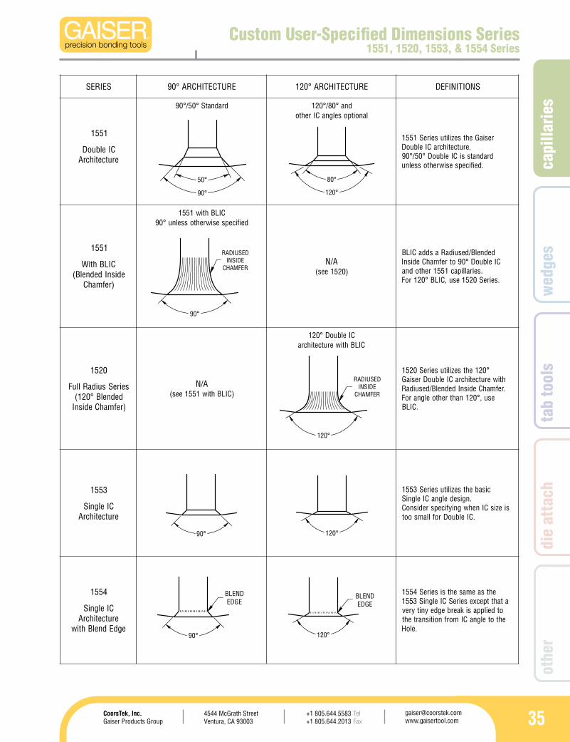
1551
CIelbuoDerutcetihcrA
dradnatS°05/°09 dna°08/°021lanoitposelgnaCIrehto
resiaGehtsezilituseireS1551.erutcetihcraCIelbuoD
dradnatssiCIelbuoD°05/°09.deificepsesiwrehtosselnu
1551
CILBhtiWedisnIdednelB(
)refmahC
CILBhtiw1551deificepsesiwrehtosselnu°09
A/N)0251ees(
dednelB/desuidaRasddaCILBCIelbuoD°09otrefmahCedisnI
.seirallipac1551rehtodna.seireS0251esu,CILB°021roF
0251
seireSsuidaRlluFdednelB°021(
)refmahCedisnI
A/N)CILBhtiw1551ees(
CIelbuoD°021CILBhtiwerutcetihcra
°021ehtsezilituseireS0251htiwerutcetihcraCIelbuoDresiaG.refmahCedisnIdednelB/desuidaR
esu,°021nahtrehtoelgnaroF.CILB
3551
CIelgniSerutcetihcrA
cisabehtsezilituseireS3551.ngisedelgnaCIelgniS
siezisCInehwgniyficepsredisnoCCIelbuoDrofllamsoot .
4551
CIelgniSerutcetihcrA
egdEdnelBhtiw
ehtsaemasehtsiseireS4551atahttpecxeseireSCIelgniS3551
otdeilppasikaerbegdeynityrevehtotelgnaCImorfnoitisnarteht
.eloH
120°
RADIUSEDINSIDE
CHAMFER
120°
80°
Custom User-Specified Dimensions Series1551, 1520, 1553, & 1554 Series
90°
50°
90° 120°
90°
BLENDEDGE
120°
BLENDEDGE
90°
RADIUSEDINSIDE
CHAMFER
36
30° 0.012305µm
R0.010254µm
10°
30°
8°
120°
IR
IROR
H
B
T
1590
4°
120°
IR
IROR
H
B
T
1591
&SEIRES.ONHSAD
*Hmµ/.ni
5.2/1000.0±
RImµ/.ni)feR(
Bmµ/.ni
**etoNeeS
ROmµ/.ni
8/3000.0±
T)ENOC°03(
mµ/.ni8/3000.0±
T)KNTBA°01(
mµ/.ni8/3000.0±
DETSEGGUSRETEMAIDERIW
mµ/.ni
C51-X951 83/5100.0 01/4000.0 85/3200.0 03/2100.0 721/0500.0 731/4500.0
82/1100.0ot32/9000.0D51-X951 83/5100.0 01/4000.0 85/3200.0 03/2100.0 041/5500.0 051/9500.0
E51-X951 83/5100.0 31/5000.0 46/5200.0 83/5100.0 251/0600.0 561/5600.0F51-X951 83/5100.0 31/5000.0 46/5200.0 83/5100.0 561/5600.0 871/0700.0G51-X951 83/5100.0 31/5000.0 46/5200.0 83/5100.0 871/0700.0 191/5700.0C71-X951 34/7100.0 01/4000.0 46/5200.0 03/2100.0 721/0500.0 731/4500.0
33/3100.0ot52/0100.0
D71-X951 34/7100.0 01/4000.0 46/5200.0 03/2100.0 041/5500.0 051/9500.0E71-X951 34/7100.0 31/5000.0 96/7200.0 83/5100.0 251/0600.0 561/5600.0F71-X951 34/7100.0 31/5000.0 96/7200.0 83/5100.0 561/5600.0 871/0700.0G71-X951 34/7100.0 31/5000.0 96/7200.0 83/5100.0 871/0700.0 191/5700.0H71-X951 34/7100.0 31/5000.0 96/7200.0 83/5100.0 191/5700.0 302/0800.0J71-X951 34/7100.0 31/5000.0 96/7200.0 83/5100.0 302/0800.0 612/5800.0D81-X951 64/8100.0 31/5000.0 17/8200.0 03/2100.0 041/5500.0 051/9500.0E81-X951 64/8100.0 31/5000.0 17/8200.0 83/5100.0 251/0600.0 561/5600.0F81-X951 64/8100.0 31/5000.0 17/8200.0 83/5100.0 561/5600.0 871/0700.0G81-X951 64/8100.0 51/6000.0 67/0300.0 83/5100.0 871/0700.0 191/5700.0H81-X951 64/8100.0 51/6000.0 67/0300.0 83/5100.0 191/5700.0 302/0800.0J81-X951 64/8100.0 51/6000.0 67/0300.0 83/5100.0 302/0800.0 612/5800.0
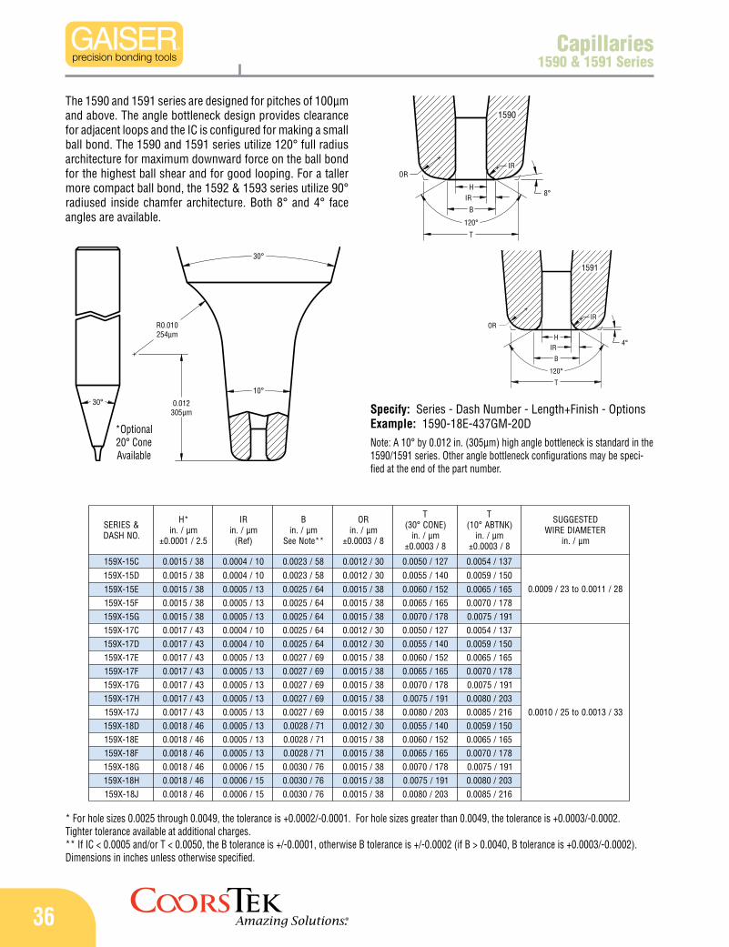
Capillaries1590 & 1591 Series
Note: A 10° by 0.012 in. (305µm) high angle bottleneck is standard in the 1590/1591 series. Other angle bottleneck configurations may be speci-fied at the end of the part number.
The 1590 and 1591 series are designed for pitches of 100µm and above. The angle bottleneck design provides clearance for adjacent loops and the IC is configured for making a small ball bond. The 1590 and 1591 series utilize 120° full radius architecture for maximum downward force on the ball bond for the highest ball shear and for good looping. For a taller more compact ball bond, the 1592 & 1593 series utilize 90° radiused inside chamfer architecture. Both 8° and 4° face angles are available.
*Optional 20° Cone Available
Specify: Series - Dash Number - Length+Finish - OptionsExample: 1590-18E-437GM-20D
* For hole sizes 0.0025 through 0.0049, the tolerance is +0.0002/-0.0001. For hole sizes greater than 0.0049, the tolerance is +0.0003/-0.0002. Tighter tolerance available at additional charges.** If IC < 0.0005 and/or T < 0.0050, the B tolerance is +/-0.0001, otherwise B tolerance is +/-0.0002 (if B > 0.0040, B tolerance is +0.0003/-0.0002).Dimensions in inches unless otherwise specified.
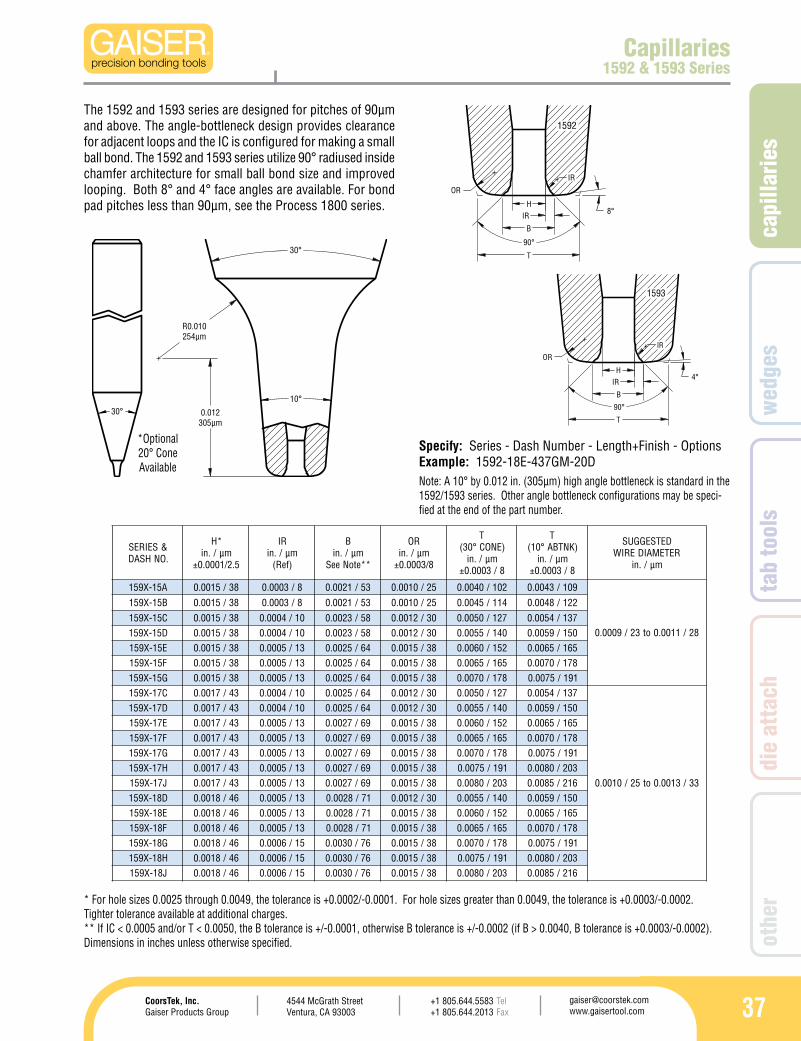
capi
llarie
s
374544 McGrath StreetVentura, CA 93003
[email protected] www.gaisertool.com
CoorsTek, Inc.Gaiser Products Group
TelFax
+1 805.644.5583+1 805.644.2013
wed
ges
tab
tool
sdi
e at
tach
othe
r
30° 0.012305µm
R0.010254µm
10°
30°
8°
IR
IR
OR
90°
H
B
T
1592
4°
90°
T
IR
OR
H
B
1593
IR
&SEIRES.ONHSAD
*Hmµ/.ni
5.2/1000.0±
RImµ/.ni)feR(
Bmµ/.ni
**etoNeeS
ROmµ/.ni
8/3000.0±
T)ENOC°03(
mµ/.ni8/3000.0±
T)KNTBA°01(
mµ/.ni8/3000.0±
DETSEGGUSRETEMAIDERIW
mµ/.ni
A51-X951 83/5100.0 8/3000.0 35/1200.0 52/0100.0 201/0400.0 901/3400.0
82/1100.0ot32/9000.0
B51-X951 83/5100.0 8/3000.0 35/1200.0 52/0100.0 411/5400.0 221/8400.0
C51-X951 83/5100.0 01/4000.0 85/3200.0 03/2100.0 721/0500.0 731/4500.0D51-X951 83/5100.0 01/4000.0 85/3200.0 03/2100.0 041/5500.0 051/9500.0E51-X951 83/5100.0 31/5000.0 46/5200.0 83/5100.0 251/0600.0 561/5600.0F51-X951 83/5100.0 31/5000.0 46/5200.0 83/5100.0 561/5600.0 871/0700.0G51-X951 83/5100.0 31/5000.0 46/5200.0 83/5100.0 871/0700.0 191/5700.0C71-X951 34/7100.0 01/4000.0 46/5200.0 03/2100.0 721/0500.0 731/4500.0
33/3100.0ot52/0100.0
D71-X951 34/7100.0 01/4000.0 46/5200.0 03/2100.0 041/5500.0 051/9500.0E71-X951 34/7100.0 31/5000.0 96/7200.0 83/5100.0 251/0600.0 561/5600.0F71-X951 34/7100.0 31/5000.0 96/7200.0 83/5100.0 561/5600.0 871/0700.0G71-X951 34/7100.0 31/5000.0 96/7200.0 83/5100.0 871/0700.0 191/5700.0H71-X951 34/7100.0 31/5000.0 96/7200.0 83/5100.0 191/5700.0 302/0800.0J71-X951 34/7100.0 31/5000.0 96/7200.0 83/5100.0 302/0800.0 612/5800.0D81-X951 64/8100.0 31/5000.0 17/8200.0 03/2100.0 041/5500.0 051/9500.0E81-X951 64/8100.0 31/5000.0 17/8200.0 83/5100.0 251/0600.0 561/5600.0F81-X951 64/8100.0 31/5000.0 17/8200.0 83/5100.0 561/5600.0 871/0700.0G81-X951 64/8100.0 51/6000.0 67/0300.0 83/5100.0 871/0700.0 191/5700.0H81-X951 64/8100.0 51/6000.0 67/0300.0 83/5100.0 191/5700.0 302/0800.0J81-X951 64/8100.0 51/6000.0 67/0300.0 83/5100.0 302/0800.0 612/5800.0
Capillaries1592 & 1593 Series
The 1592 and 1593 series are designed for pitches of 90µm and above. The angle-bottleneck design provides clearance for adjacent loops and the IC is configured for making a small ball bond. The 1592 and 1593 series utilize 90° radiused inside chamfer architecture for small ball bond size and improved looping. Both 8° and 4° face angles are available. For bond pad pitches less than 90µm, see the Process 1800 series.
Note: A 10° by 0.012 in. (305µm) high angle bottleneck is standard in the 1592/1593 series. Other angle bottleneck configurations may be speci-fied at the end of the part number.
*Optional 20° Cone Available
Specify: Series - Dash Number - Length+Finish - OptionsExample: 1592-18E-437GM-20D
* For hole sizes 0.0025 through 0.0049, the tolerance is +0.0002/-0.0001. For hole sizes greater than 0.0049, the tolerance is +0.0003/-0.0002. Tighter tolerance available at additional charges.** If IC < 0.0005 and/or T < 0.0050, the B tolerance is +/-0.0001, otherwise B tolerance is +/-0.0002 (if B > 0.0040, B tolerance is +0.0003/-0.0002).Dimensions in inches unless otherwise specified.
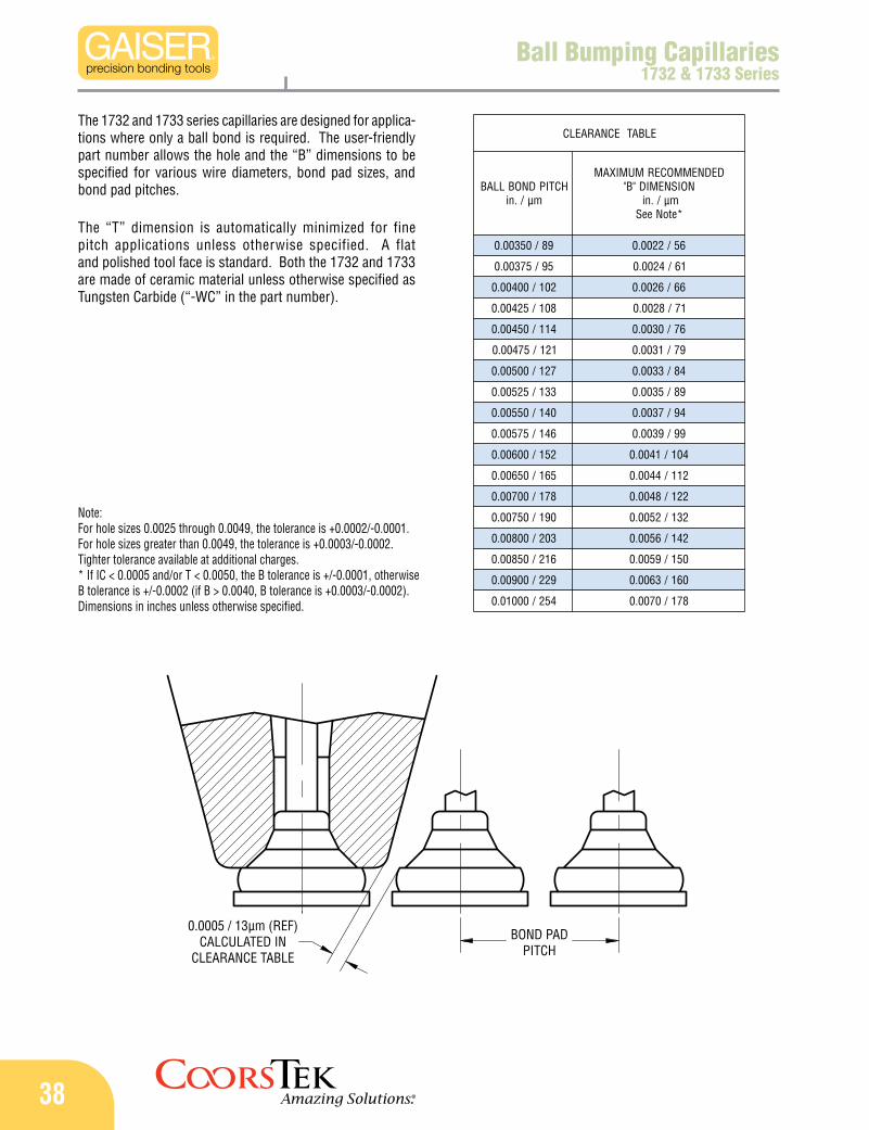
38
BOND PADPITCH
0.0005 / 13µm (REF)CALCULATED IN
CLEARANCE TABLE
ELBATECNARAELC
HCTIPDNOBLLABmµ/.ni
DEDNEMMOCERMUMIXAMNOISNEMID"B"
mµ/.ni*etoNeeS
98/05300.0 65/2200.0
59/57300.0 16/4200.0
201/00400.0 66/6200.0
801/52400.0 17/8200.0
411/05400.0 67/0300.0
121/57400.0 97/1300.0
721/00500.0 48/3300.0
331/52500.0 98/5300.0
041/05500.0 49/7300.0
641/57500.0 99/9300.0
251/00600.0 401/1400.0
561/05600.0 211/4400.0
871/00700.0 221/8400.0
091/05700.0 231/2500.0
302/00800.0 241/6500.0
612/05800.0 051/9500.0
922/00900.0 061/3600.0
452/00010.0 871/0700.0
Ball Bumping Capillaries1732 & 1733 Series
The 1732 and 1733 series capillaries are designed for applica-tions where only a ball bond is required. The user-friendly part number allows the hole and the “B” dimensions to be specified for various wire diameters, bond pad sizes, and bond pad pitches.
The “T” dimension is automatically minimized for fine pitch applications unless otherwise specified. A flat and polished tool face is standard. Both the 1732 and 1733 are made of ceramic material unless otherwise specified as Tungsten Carbide (“-WC” in the part number).
Note: For hole sizes 0.0025 through 0.0049, the tolerance is +0.0002/-0.0001. For hole sizes greater than 0.0049, the tolerance is +0.0003/-0.0002. Tighter tolerance available at additional charges.* If IC < 0.0005 and/or T < 0.0050, the B tolerance is +/-0.0001, otherwise B tolerance is +/-0.0002 (if B > 0.0040, B tolerance is +0.0003/-0.0002). Dimensions in inches unless otherwise specified.
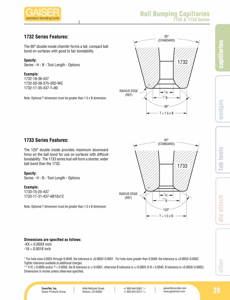
capi
llarie
s
394544 McGrath StreetVentura, CA 93003
[email protected] www.gaisertool.com
CoorsTek, Inc.Gaiser Products Group
TelFax
+1 805.644.5583+1 805.644.2013
wed
ges
tab
tool
sdi
e at
tach
othe
r
30°(STANDARD)
90°
H
B
T = 1.5 x B
RADIUS EDGE(REF)
**
*
1732
30°(STANDARD)
120°
T = 1.5 x B
B
HRADIUS EDGE(REF)
***
1733
Ball Bumping Capillaries1732 & 1733 Series
1732 Series Features:
Specify: Series - H - B - Tool Length - Options
Example: 1732-18-36-437 1732-20-38-375-20D-WC 1732-17-35-437-T=90
The 90° double inside chamfer forms a tall, compact ball bond on surfaces with good to fair bondability.
1733 Series Features:
Specify:Series - H - B - Tool Length - Options
Example:1733-15-25-4371733-17-31-437-AB10x12
The 120° double inside provides maximum downward force on the ball bond for use on surfaces with difficult bondability. The 1733 series tool will form a shorter, wider ball bond than the 1732.
Dimensions are specified as follows:-XX = 0.00XX inch-18 = 0.0018 inch
* For hole sizes 0.0025 through 0.0049, the tolerance is +0.0002/-0.0001. For hole sizes greater than 0.0049, the tolerance is +0.0003/-0.0002. Tighter tolerance available at additional charges.** If IC < 0.0005 and/or T < 0.0050, the B tolerance is +/-0.0001, otherwise B tolerance is +/-0.0002 (if B > 0.0040, B tolerance is +0.0003/-0.0002).Dimensions in inches unless otherwise specified.
Note: Optional T dimension must be greater than 1.5 x B dimension
Note: Optional T dimension must be greater than 1.5 x B dimension
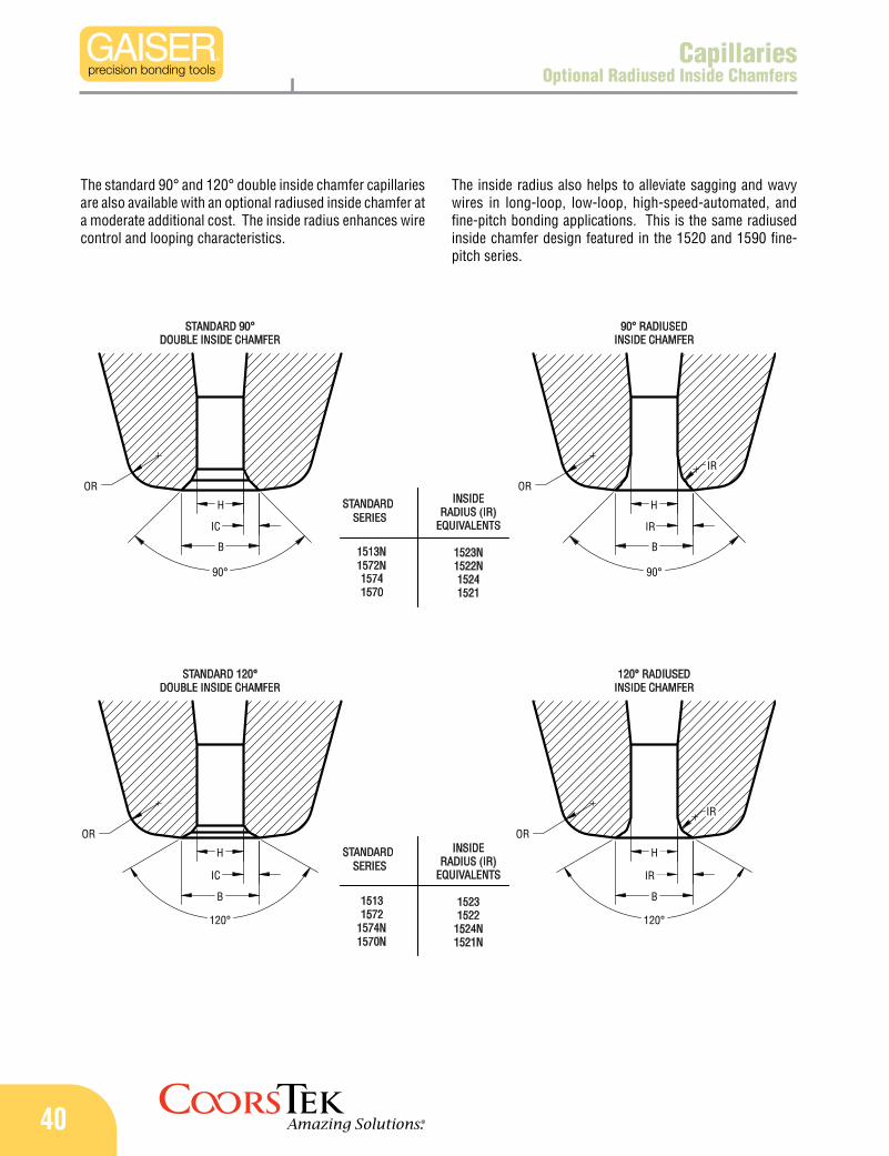
40
90° RADIUSEDINSIDE CHAMFER
120° RADIUSEDINSIDE CHAMFER
INSIDERADIUS (IR)
EQUIVALENTS
15231522
1524N1521N
STANDARDSERIES
1570N1574N15721513
15701574
1572N1513N
SERIESSTANDARD INSIDE
RADIUS (IR)EQUIVALENTS
1523N1522N15241521
STANDARD 90°DOUBLE INSIDE CHAMFER
STANDARD 120°DOUBLE INSIDE CHAMFER
IR
B
IR
120°
90°
B
IR
H
H
OR
OR
H
OR
B
90°
IC
IC
120°
OR
H
B
IR
CapillariesOptional Radiused Inside Chamfers
The standard 90° and 120° double inside chamfer capillaries are also available with an optional radiused inside chamfer at a moderate additional cost. The inside radius enhances wire control and looping characteristics.
The inside radius also helps to alleviate sagging and wavy wires in long-loop, low-loop, high-speed-automated, and fine-pitch bonding applications. This is the same radiused inside chamfer design featured in the 1520 and 1590 fine-pitch series.