
BIM Execution Plan - ggcity.org · • Project Information o BIM Execution Plan o Coordination...
29
BIM Execution Plan v001 BIM Execution Plan Great Wolf Lodge Phase II - Construction Pablo Medina and Matthew Imber 10/16/2013
-
Upload
phungquynh -
Category
Documents
-
view
227 -
download
1
Transcript of BIM Execution Plan - ggcity.org · • Project Information o BIM Execution Plan o Coordination...

BIM Execution Plan v001
BIM Execution Plan
Great Wolf Lodge Phase II - Construction
Pablo Medina and Matthew Imber
10/16/2013

Page 2 of 9
Table of Contents I. Introduction .......................................................................................................................................... 3
Project Information ............................................................................................................................... 3
Collaboration Team ............................................................................................................................... 3
II. Modeling Plan ....................................................................................................................................... 4
Model Manager..................................................................................................................................... 4
Model Scope ......................................................................................................................................... 4
III. Construction Phase Coordination Plan ................................................................................................ 5
Coordination Plan Narrative: ................................................................................................................ 5
General Model Requirements ............................................................................................................... 5
BIM Kickoff Meeting ............................................................................................................................. 7
Technical Specifications of Coordination Models ................................................................................. 7
Collaboration Details ............................................................................................................................. 8
IV. BIM Quality Assurance and Control ..................................................................................................... 8
Quality Control Plan .............................................................................................................................. 9
Page 3 of 9
I. Introduction The intent of this BIM Execution Plan is to provide a framework that allows the Great Wolf Lodge team
to deploy building information modeling (BIM) technology and best practices for improved
communication and efficient collaboration. This plan delineates roles and responsibilities of each party,
the detail and scope of information to be shared and relevant business processes.
Project Information
Project Name: Great Wolf Lodge
Project Address: 12681 Harbor Blvd., Garden Grove CA, 92840
Project Description: Water Park and Hotel
Collaboration Team
Contact Name Role/Title Company Email Phone
Ilyes Nouizi Architect Ware Malcomb [email protected] 949.788.4176
Harold Bessette Fire Protection XL Fire [email protected] 714.554.6132 Patrick George Plumbing Pan Pac [email protected] 949.474.9170
Joel Roderick Water Park Design Water Park Tech [email protected]
Chad Ford Mechanical Couts [email protected] 951.278.5560 ext 126
James Grant Electrical Helix [email protected]
Pablo Medina GC – Model Manager Turner [email protected] 714.290.8097

Page 4 of 9
II. Modeling Plan
Planning in advance is the key to a successful collaborative process. The modeling plan describes the
role of the model manager and the process for sharing the model information.
Model Manager
Project Phase Model Manager - Construction
Implementation Documents/
Construction Documents Phase
Pablo Medina
714.290.8097
The Construction Model Manager has the following responsibilities. They include, but are not limited to:
• Assuring models can easily be shared from one party to another
• Combining or linking multiple models
• Participating in design review and model coordination sessions
• Communicating issues back to the internal and cross-company teams
• Enforcing file naming accuracy
• Managing version control
• Properly storing the models in the collaborative project management system
• Facilitate Construction Phase Coordination
Model Scope
Please refer to Exhibit J about the scope of the model for each phase.
Level of Detail definitions used in Exhibit J is as follows:
Level of Development (LOD) Descriptions
Model
Content
100 200 300 400 500
Design
&
Coord.
Non-geometric
data
or line work, areas,
volumes zones,
etc.
- 2D
representations
Generic elements
shown in three
dimensions
- maximum size
- purpose
Specific elements
Confirmed 3D
Object Geometry
- dimensions
- capacities
- connections
Shop drawing/
fabrication
- purchase
- manufacture
- install
- specified
As-built
- actual

Page 5 of 9
III. Construction Phase Coordination Plan
Coordination Plan Narrative:
Turner will provide a background model that will consist of the Architecture and Superstructure
(Foundation, Structure). This model will be provided to the trades and will be used as a reference model
primarily to design within the spatial limitations of the core and shell of the building design. The trades
will collaborate with each other to avoid system clashes.
Turner will consolidate the models in Navisworks and run batches of clashes between trades. A report
will be generated which summarizes the conflicts. The clashes will be reviewed in coordination
meetings. Trades will resolve the clashes and post updated models to the designated
repository/collaborations site. Turner will re-run a clash check to confirm previously identified clashes
have been resolved and will update the clash reports with any new clashes as a result of model and
design updates.
Once the clashes have been resolved, coordinated drawings will be produced/updated reflecting the
resolutions from the coordination meetings and the subsequent model changes agreed upon. The
construction documents will reflect the clash resolutions of the coordination cycles and will be
incorporated into the installation/shop drawings.
General Model Requirements
Origin Point: All models must be in the correct location in 3D Space (x, y, and z coordinates). This project
is using shared coordinates (real world). Contact the contractor in order to received origin point details.
These coordinates will be set by Contractor/architect and distributed to all consultants & trade
contractors for their use. This includes correct floor elevation(s) (z coordinates). The correct insertion

Page 6 of 9
point is critical and ensures that each model will align properly for the master aggregate Model without
modification.
Origin Point: N 154’ – 4 61/64”
E 218’ – 7 37/256”
Elevation: 112’ 0”
Angle to true North 270.672*
This will be the Corner of H1 and HE
Tolerances: Model(s) and Model Elements must be within 1/8” of theoretical dimensions. Tolerances for
specific items and systems will be determined as necessary. Model tolerances are not to be construed as
construction tolerances.
Units: Imperial units. One (1) unit in the model equals 0’-1”
Scale: BIM/3D Models need to be in the correct scale and units. One unit (in the model) equals one inch.
Best Practices: Contributors to the model(s) shall follow to the best of their ability the best practices
listed in the "Autodesk Revit Platform 2014 Technical Note Model Performance". Geometry from CAD
applications such as AutoCAD, IFC or MicroStation shall not be imported or linked into the model. Image
files shall not be imported or linked into the model to represent geometry. Revit Warnings should be
kept to a minimum and model geometry called out in the Model Requirements section of this document
shall not be associated with any Warnings.
Coordination Zones: The Design Model has to reflect the coordination process and often has to be split
up by zones. Coordination zones will be determined during the kick-off meeting with input from the
project team. These zones will follow the construction schedule.
Page 7 of 9
BIM Kickoff Meeting
At the beginning of the project, Contractor will hold a BIM introduction or "kickoff" meeting to establish
the BIM program(s), procedures, organization and setups for all members of the Design Team. Topics to
be covered are:
• Project Information
o BIM Execution Plan
o Coordination Schedule and Critical Path Deadlines
o Version & Build of Revit to be used on the project
o Identify Software tools to be used on the project
o General Requirements / Deliverables
• Spatial Coordination
o Model Divisions and Sharing
o Building Areas of Responsibility (Shared Models)
o Team Responsibility (BIM Points of Contact)
o File Divisions / Organization
• Best Practices / Guidelines
o Anticipated Model Uses
o Procedure for Updates, Coordination and Communication
o Best Practices
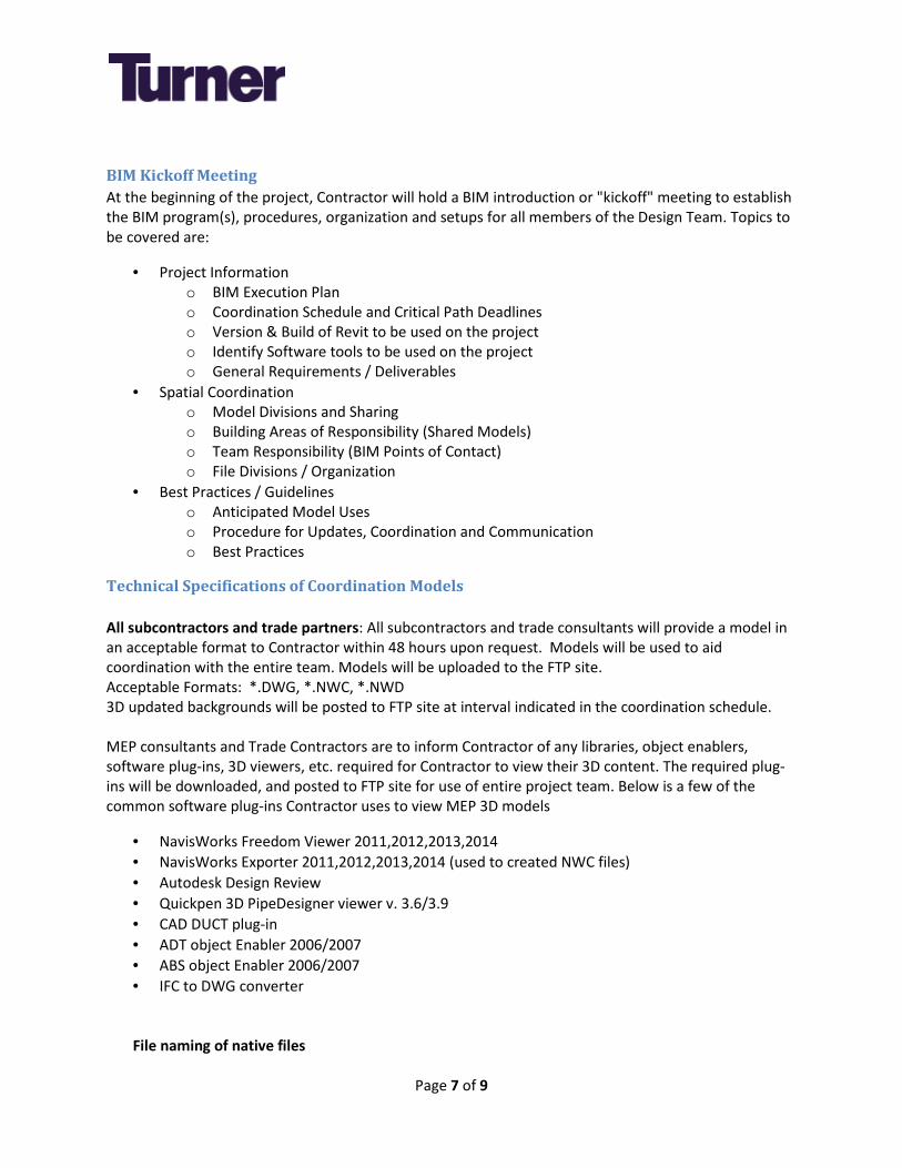
Technical Specifications of Coordination Models
All subcontractors and trade partners: All subcontractors and trade consultants will provide a model in
an acceptable format to Contractor within 48 hours upon request. Models will be used to aid
coordination with the entire team. Models will be uploaded to the FTP site.
Acceptable Formats: *.DWG, *.NWC, *.NWD
3D updated backgrounds will be posted to FTP site at interval indicated in the coordination schedule.
MEP consultants and Trade Contractors are to inform Contractor of any libraries, object enablers,
software plug-ins, 3D viewers, etc. required for Contractor to view their 3D content. The required plug-
ins will be downloaded, and posted to FTP site for use of entire project team. Below is a few of the
common software plug-ins Contractor uses to view MEP 3D models
• NavisWorks Freedom Viewer 2011,2012,2013,2014
• NavisWorks Exporter 2011,2012,2013,2014 (used to created NWC files)
• Autodesk Design Review
• Quickpen 3D PipeDesigner viewer v. 3.6/3.9
• CAD DUCT plug-in
• ADT object Enabler 2006/2007
• ABS object Enabler 2006/2007
• IFC to DWG converter
File naming of native files

Page 8 of 9
o For those who are using the Autodesk products, we request that you do not change the
name of the original file throughout the model progression. If the authoring file changes
names then all clash history gets lost once it is brought into Navisworks.
Collaboration Details
Repository Site
ViCon Server: The project will be using a server that enables collaborators to upload their specific model.
The server will restrict the file naming (see file naming convention). User accounts will be set up for all
collaborators.
Link to website: www.turnervicon.com
• File Naming Conventions for Vicon
o It is critical that all project team members use a mandated file naming convention for their
file’s name. Turner will provide the detailed file naming convention to project team
members. An example would be as follows: “PROJECT_RESPONSIBILITY_CONSTRUCTION PHASE_TRADE_COORD PHASE_ZONE_VERSION_DATA DATE”
o Any files that do not follow the file naming convention will be deleted and removed from
the server at anytime without any notification.
Example of File Naming
GWL_HELIX_CON_ELEC_PH01_ZONE01_V001_2013-11-17
GWL_COUTS_ CON_HVAC_PH??_ZONE??_V???_????-??-??
GWL_PPM_ CON_PG_PH??_ZONE??_V???_????-??-??
GWL_XL_ CON_FP_PH??_ZONE??_V???_????-??-??
GWL_RAYMOND_ CON_EXT SYSTM_PH??_ZONE??_V???_????-??-??
GWL_MARTIN BRO_CON_FRAMING_PH??_ZONE??_V???_????-??-??
GWL_LARGO_CON_CONCRETE_PH??_ZONE??_V???_????-??-??
GWL_W&W_CON_STRCT STEEL_PH??_ZONE??_V???_????-??-??
GWL_COASTLINE_CON_FOOD SRVC_PH??_ZONE??_V???_????-??-??
GWL_WATERTECH_CON_WATERPARK_PH??_ZONE??_V???_????-??-??
• Uploading Frequency
o 3D updated backgrounds and trade models will be posted to ViCon Server on every
Wednesday no later than 12:00 P.M. PST.
IV. BIM Quality Assurance and Control
The Model will be checked by the Contractor and Design Team based on processes described below. The
project team member performing the QA /QC analysis should clearly communicate the analysis

Page 9 of 9
requirements to the original model authoring team member and provide transparent deliverables to the
team about the progress of QA /QC.
Quality Control Plan
CHECKS DEFINITION RESPONSIBLE
PARTY
SOFTWARE
PROGRAM(S) FREQUENCY
VISUAL CHECK
Ensure there are no
unintended model
components and the
design intent has been
followed
MEA &
Contractor
Model
Manager
Revit 2014,
NavisWorks
2014
Weekly
CONSTRUCTABILTY
REPORTS
Detect problems in the
model where two
building components
are clashing including
soft and hard
Pablo
Medina
NavisWorks
2014
As
determined
by
coordination
schedule
CONTENT PLAN
CHECK
Ensure that the Content
Plan Guidelines have
been followed (fonts,
dimensions, line styles,
levels/layers, etc)
Revit 2014
Before major
design
milestone

akim
Text Box
EXHIBIT J
Client – McWhinney/Great Wolf Turner Construction Company
Project – Great Wolf Lodge – Garden Grove Date: 10/16/2013
Page 1 of 19 Template 05/14/09
BIM Implementation Plan
The Great Wolf Lodge – Garden Grove Project shall utilize 3D Modeling for the coordination of building elements and systems. Review the Project Plans and Specifications in conjunction with this document for additional project specific information and scope related to Coordination, BIM, and associated deliverables.
Section 1 - Virtual Design and Construction Techniques
1- Subcontractor agrees to participate in the use of digital/computer based three dimensional models and other related functionality, generally referred to as building information modeling (such models and functionality are referred to herein as BIM) as Turner may determine to be beneficial for use in facilitating coordination, sequencing, scheduling and/or production of as-built depictions of the Project and performance of the Work and as hereafter provided. The Subcontractor’s costs of such participation are included in the Price unless explicitly outlined herein.
2- Subcontractor shall provide digital submissions of information describing its respective
Work in a form and manner that Turner may require and that can be loaded into a BIM assembled by Turner.
3- Subcontractor's submissions shall be of sufficient detail to enable accurate and complete
clash detection and shall be provided by Subcontractor at a point in time that is reasonably in advance of Subcontractor’s shop drawing submittals and the subsequent on site construction of the Subcontractor’s Work and such submissions shall contain such details and follow such procedures as Turner may require.
4- The digital format of such BIM submissions shall be as described herein (specifying the
necessary digital formats, software requirements, etc.), which will be provided to subcontractor after execution of Agreement and prior to the start of coordination.
5- Subcontractor shall participate in such BIM coordination and review meetings as Turner
may require and agrees that, as a result of the information exchanged at such meetings, both the digital submission and the Work depicted in the Subcontractor’s digital submission may be required to be changed by Subcontractor to achieve coordination with other elements of the Project being provided by others. Such changes shall be accomplished at no increase in the Price or Time of Completion. Subcontractor acknowledges that such meetings will require attendance of personnel that are familiar with both the data entry aspects of the BIM as well as an understanding of the Work to be performed and its relation to other elements of the Project, and subcontractor therefore agrees that personnel conversant in both shall be on site during the coordination phase and attend all such meetings.
6- Subcontractor agrees that neither the BIM nor the use of the BIM is in lieu of nor intended
to relieve the Subcontractor of its responsibilities under the Subcontract, including to (i) coordinate its Work with the work of others involved in the Project and (ii) strictly comply with the other requirements of the Subcontract Agreement and the Contract Documents. It is expressly understood and agreed that, notwithstanding the requirement for submittals in connection with the BIM, traditional shop drawings and other submissions shall be required of Subcontractor as required by the Contract Documents and no party shall be

Client – McWhinney/Great Wolf Turner Construction Company
Project – Great Wolf Lodge – Garden Grove Date: 10/16/2013
Page 2 of 19 Template 05/14/09
liable to the other for any claim, dispute, controversy, cost or expense arising solely out of the use of the BIM.
7- Turner does not waive any of its intellectual property rights and shall have the sole and
exclusive right to use the BIM and all submissions made by Subcontractor as it deems appropriate, whether during or after construction.
8- Subcontractor agrees that notwithstanding the fact that it may participate in the BIM
process or receive information or materials from others in connection with the Project through the course of the use or development of the BIM, it shall not take any position that the receipt of such participation or information has or will, in any respect, operate to waive, release or otherwise invalidate any of its obligations or responsibilities under the Subcontract or any intellectual property rights (copyrights, trademarks/logos, patents, etc.) that may apply to such information or materials.
9- Subcontractor acknowledges and agrees that Turner shall incur no responsibility or
liability with respect to the BIM or the use thereof, including that resulting from errors, omissions or deficiencies in the BIM. In the event that Subcontractor provides deficient information or data that does not represent the Work it will be ultimately providing, that is corrupted, that contains a virus and/or that otherwise damages the BIM, Subcontractor shall bear all costs associated with reconstructing the BIM and to otherwise remediate such deficiencies or their effects.
10- In the event the Subcontractor discovers any error, inconsistency or omission in its
information or submissions, the information or submissions provided by others or any BIM, it shall promptly report the same to Turner via written notice which shall contain all relevant specifics.
11- Subcontractor acknowledges that the BIM may require updating throughout the life of the
Project to addresses any changes to the Work so that the BIM at the conclusion of the Project accurately depicts the Work as actually performed and installed. Subcontractor agrees to promptly update and provide revised submissions to Turner throughout the course of the Project so that the BIM at the conclusion of the Project accurately depicts the Work as actually performed and installed.
12- The foregoing process is in addition to the Subcontractor’s obligations to make the
traditional submissions and shall not relieve or lessen in any way the Subcontractor’s obligations contained throughout this Agreement and the other Contract Documents, defined in Article II of this Agreement.
Section 2 - BIM to Field
1. Turner Construction Company intends to implement Innovative Technologies and Processes
that Subcontractors are required to participate in and collaborate. The following technologies are targeted for implementation.
a. Online Project Documentation – Turner intends on implementing an online project
document system to access the most current project information via the internet. Participation of Trade contractors is expected. Each individual user shall have their own login, group logins may not be allowed and each subcontractor shall comply with security

Client – McWhinney/Great Wolf Turner Construction Company
Project – Great Wolf Lodge – Garden Grove Date: 10/16/2013
Page 3 of 19 Template 05/14/09
requirements as directed. Cost of each user shall be paid by each Trade and is estimated at $15.00 for each login/user per month.
b. Tablet PCs – Turner intends to utilize Windows Tablet PCs to access project information in the field. Each subcontractor is expected to take advantage of the online project document system to access the most current information and implement processes in the field.
c. Please see the following list for some examples.
i. Real time QA/QC processes ii. Field Equipment and Material verification and audits iii. Daily reporting iv. RFI tracking v. Communication vi. As-Builts vii. Safety viii. Punch lists ix. Work to complete lists x. Non-compliant work
d. Prefabrication – Turner intends on using the BIM process to realize prefabrication potential with the goal to expedite installations and improve schedule performance. Subcontractors are expected to collaborate and identify elements and systems that can be prefabricated.
e. Turner will utilize 3D Scheduling based on Lean Construction Principals to plan, monitor and collaborate on this project. All trades are required to participate.
i. Last Planner System (Pull Planning) and Flow line Scheduling Turner will implement the Last Planner System (Pull Planning) from key milestone phase to phase to create a “production plan” to execute design, shop drawing / submittals, procure and construction, commission, move-in. This production plan is put in Control and only the milestones in common with the baseline schedule are manually compared for ahead or behind of the various baseline milestone dates.
ii. Overview of Lean Production Schedule and Monitoring Process It’s commonly acknowledged that reducing the variation in starts and stops of the parade of trades and leveling capacity across trade specialists’ handoffs reduces waste and improving smooth flow. Flow line scheduling helps visualize the flow of construction by adding location information to the schedule. The INITIAL Flow line Schedule is built from the traditional Gantt chart schedule and it is also based on CPM principals. However by adding the location to the schedule, and using collaborative pull planning for initial parade of trades, the visualization of crew capacity and flow becomes more transparent and easier to communicate. It also becomes the basis for continual improvement as the crews identify incremental improvements and innovations. The suggested workflow includes the following steps:
1) Create Work Breakdown Structure (WBS) starting with the Turner standard template for this building system / assembly.
2) Import WBS activity list from the Turner conceptual Critical Path Method Milestone schedule.
3) Add high-level quantities; define conceptual production rate and minimum crew size
4) Optimize flow for locations and hold this information in Turner Team ONLY

Client – McWhinney/Great Wolf Turner Construction Company
Project – Great Wolf Lodge – Garden Grove Date: 10/16/2013
Page 4 of 19 Template 05/14/09
5) Optimize durations and balance resources.
6) Review quantities based on the Building Information Model (BIM)
7) Plan and conduct a Pull Planning meeting with the key trade partners and other stakeholders for this building system / assembly.
8) For repetitive rooms and or building areas, etc. the team would create a pull plan of a typical sequence ( small batch size )
9) IF mockups were needed, the mock up would be videotaped during assembly to learn improvement ideas and incorporate these in the Flow line.
10) Turner Team would use the “INITIAL FLOWLINE schedule from the “Baseline” as a “guide” during the Pull Plan Meeting – refer to this flow line to ask questions during the pull plan meeting.
11) Insert the resulting Pull Plan results into a FLOWLINE “Production Plan”
12) Analyze the Flow line Production Plan
13) Review the Flow line production plan with the stakeholders – incorporate improvements – run what-if scenarios with the trades and stakeholders.
14) Issue the Flow line Production Plan and establish Baseline Schedule for the team’s use in Look Ahead Planning, and Weekly Work Planning
15) Maintain and update 3D coordination schedule from “milestone to milestone” only.
16) Review updated baseline schedule with PM and potential Subs
17) Discuss production rates and crew sizes with subcontractors
iii. Information requirements for schedule planning phase:
1) Task list for monitoring
2) Assumed quantities (or verification of 3D model quantities) per task
3) Production rates per task(/quantity)
4) Productivity rates in average conditions (man-hours/unit or units/man-hr.)
5) Optimal crew sizes
6) Resource constraints (if any)
7) Schedule and production rate requirements will determine the required number of crews
8) Preferred/optimum Location Breakdown Structure - locations should be less than 5 days work for each monitored task
9) Desired location completion order (if any)
iv. After award, the subcontractor will be expected to review their information in the Flow line schedule, including committing to the overall resource graphs.
v. Operational requirements during production:
1) Subcontractor will report quantities installed or areas completed along with DCR daily.
2) DCR will include actual resources daily (total number of people working on each task location)
3) DCR will include actual start and finish dates in each location on weekly basis validated by Turner
4) Actual production rate (units / day) is used to calculate schedule forecasts
5) Use PPC (Planned Percent Complete) monitoring to provide feedback

Client – McWhinney/Great Wolf Turner Construction Company
Project – Great Wolf Lodge – Garden Grove Date: 10/16/2013
Page 5 of 19 Template 05/14/09
6) If a subcontractor is not meeting their required production rate, the team will evaluate the need for additional resources. Subcontractor needs to commit to actions to restore required production rate if the production rate is low due to reasons within their influence (for example, too few resources, low skill level, material logistics etc.). Actions can include: increasing crew size, working overtime, improving productivity by changing work methods
7) Billings might also be evaluated on a location basis. Subcontractors should try to completely finish one location before moving on to another, where possible. Billings should reflect the actual quantities in place evaluated using the 3D model when available. If locations cannot be fully completed because of reasons outside of subcontractors influence, partial billing is allowed but a location-based punch list should be created for the remainder.
8) Subcontractors should create a list of all prerequisites they need in order to be able to complete a task in a location (e.g. design, materials, prerequisite work, clean workspace)
9) Upcoming resource requirements are discussed weekly in subcontractor meetings (required manpower and production rates in the next 4-6 weeks)
vi. Change orders:
1) For each CO a labor estimate (in man-hours) and production rate is required
Section 3 - The Roles and Responsibilities of Each Subcontractor are Defined Below and Within “Minimum 3D Modeling Coordination Scope” at the End of This Document:
1. Turner Construction Company will make available a BIM Server/coordination model repository site provided by Turner or a trusted 3
rd party collaboration site (Autodesk
collaboration sites) that will enable all project parties to upload and download their respective “in progress shop models,” manage electronic drawing files or models and other electronic documents used in the coordination process. Turner may require that subcontractors divide their systems models by floors, zones, and/or areas in order to better manage the coordination process in a manner that is most conducive to meeting the project’s schedule and needs.
2. Turner will provide 3-Dimensional Architectural and Structural Models based on the design for use as backgrounds for coordination. Models will only include basic architectural features, such as the floors, a rough approximation of ceilings chases, door openings, partitions exterior wall surfaces, window openings, roofs, elevator shafts, and stairs, and basic Structural features such as slabs and walls, steel framing – columns, beams, and major structural elements. Each Trade is ultimately responsible for coordinating to all information contained in the 2-Dimensional Contract Drawings and Specifications as related to their work. The model(s) Turner will provide are used as diagrammatic representation only and is not to be relied upon for their accuracy nor as a reflection of the design, design intent, or representation of existing conditions. The trade subcontractor is not required nor encouraged to wait for the distribution of 3D background models by Turner to begin their engineering and drafting efforts. Each subcontractor shall proceed with the most haste using the 2D contract documents to begin their engineering, drafting, and modeling in order to meet the project schedule.

Client – McWhinney/Great Wolf Turner Construction Company
Project – Great Wolf Lodge – Garden Grove Date: 10/16/2013
Page 6 of 19 Template 05/14/09
Trades Required to provide Models in 3D
3. The Concrete Contractor will generate and provide, in a timely manner, a 3-Dimensional model of their structural concrete scope of work in addition to their contractually required 2-Dimensional documentation. The 3-Dimensional model will represent an “as fabricated” fully detailed level of information. The fabrication level detailed model shall include, but is not limited to, control joints, footings, decks, slabs, sheer walls, columns, tilt-up panels, block outs, seismic joints, slab depressions and slopes, Post Tension Cables, Stud Rails, shoring and re shoring elements etc necessary for the successful coordination of other building trades. These models shall be updated and maintained to reflect changes in the work as a result of coordination or design changes and shall be delivered at the end of the project as an “as built” record model of the concrete reinforcement system in its entirety.
4. The Structural Steel Contractor will generate and provide, in a timely manner, a 3-
Dimensional model of their structural scope of work in addition to their contractually required 2-Dimensional documentation. The 3-Dimensional model will represent an “as fabricated” fully detailed level of information. The fabrication level detailed model shall include, but is not limited to, major structural members such as trusses, beams, columns, etc, as well as secondary and miscellaneous steel connections including gusset plates, bracing, angles, knife plates, etc necessary for the successful coordination of other building trades. . These models shall be updated and maintained to reflect changes in the work as a result of coordination or design changes and shall be delivered at the end of the project as an “as built” record model of the structural steel system in its entirety.
5. The HVAC Contractor will generate and provide in a timely manner 3D Models of the HVAC Systems including, but not limited to, duct work, piping, and all equipment installed in the HVAC Scope of work (Fans, AHU’s, Built Up AHU’s., pumps, tanks, valves, controls, heat exchangers, Smoke & Fire Dampers, All Valves (including valve stems and handles), gauges & control valves, Insulation on piping & Ductwork, Hangers & Seismic Bracing, Diffusers, Registers, louvers, grilles, High & low point drains, Starters, Points of connection, etc.). The HVAC Contractor shall also include in the 3D model Concrete Equipment pads, inertia pads and Access Doors. The HVAC Contractor shall identify under separate drawing layer Access doors and Accessibility requirements for above listed items for code and maintenance purposes.
6. The Plumbing Contractor will generate and provide in a timely manner 3D Models of the Plumbing Systems including, but not limited to, all piping systems, and equipment installed in the Plumbing Scope of work. (Domestic Water, Chilled Water, Steam, Storm/Roof Leaders, pumps, tanks, water heaters, in wall carriers, In wall plumbing equipment., All Valves, gauges & control valves, Insulation on piping, Supports, Hangers & Seismic bracing, Clean-outs, Points of connection, trench drains, etc.). The Plumbing Contractor shall also include in the 3D model Concrete Equipment pads, inertia pads and Access Doors. The Plumbing Contractor shall identify under separate drawing layer Access doors and Accessibility requirements for above listed items for code and maintenance purposes. In addition, the Plumbing Contractor shall coordinate and model under a separate drawing layer all temporary systems to aid in construction sequencing.
7. The Fire Suppression System Contractor will generate and provide in a timely manner
3D Models of the Fire Suppression Systems including, but not limited to, all risers, main and branch piping, (including heads), pumps, controllers, ATS, and equipment installed in the Fire Suppression System Scope of work. (Preaction System, Dry System, and Main Fire Suppression Systems, Hangers & Seismic Bracing, Valve Assemblies, Drain valves,

Client – McWhinney/Great Wolf Turner Construction Company
Project – Great Wolf Lodge – Garden Grove Date: 10/16/2013
Page 7 of 19 Template 05/14/09
Fire Department Valves, etc.) The Fire Suppression System Contractor shall also include in the 3D model Concrete Equipment pads, inertia pads and Access Doors. The Sprinkler Contractor shall identify under separate drawing layer Access doors and Accessibility requirements for above listed items for code and maintenance purposes. In addition, the Fire Suppression System Contractor shall coordinate and model under a separate drawing layer all temporary systems to aid in construction sequencing.
8. The Electrical Contractor will generate and provide in a timely manner 3D Models of the Electrical Systems including, but not limited to, all conduit systems, and equipment installed in the Electrical Scope of work. (Individual Conduits over 1”, racks carrying more than 4 conduits 1” and smaller, panels, transformers, switch/paralleling gear, ATS’s, generators, cable tray, cable trenches, data racks, starters, VFD’s, Hangers & Seismic Bracing, etc. for Normal, Emergency and Isolated Power Systems). The Electrical Contractor shall also include in the 3D model Equipment pads, inertia pads, Light Fixtures, Exit Signs, Fire Alarm, Speakers, AV Equipment, Recessed Electrical devices and Access Doors. The Electrical Contractor shall identify under separate drawing layer Access doors and Accessibility requirements for above listed items for code and maintenance purposes. In addition, the Electrical Contractor shall coordinate and model under a separate drawing layer all temporary power distribution to include transformers, spider boxes, distribution centers, cabling, etc. to aid in construction sequencing.
9. The Drywall / Metal Framing Contractor will generate in a timely manner 3D Models of
the framing and partition walls including but not limited to all framed partitions and shafts installed in the Drywall / Framing Scope of work (vertical and horizontal shafts with studs, full height walls with studs, top track, kickers and stickers/z-clips, partial height walls with kickers, soffits with studs, exit passageways, joists and kickers, box headers and penetrations, curtain track, compression posts, king studs at all doors and windows and where required by the contract documents, backing, handrails and corner guards). The Drywall / Metal Framing Contractor shall also validate and maintain the floor plan and identify rated walls by color and pattern as well as horizontal shafts and wall types. After coordination and prior to field installation, identify and detail priority walls and leave out walls as coordinated with MEP trades. Provide composite submittal package to include access panels & devices in hard lids as designated by MEP subcontractors.
10. The Heavy Timber Contractor will generate and provide, in a timely manner, a 3-
Dimensional model of their scope of work in addition to their contractually required 2-Dimensional documentation. The 3-Dimensional model will represent an “as fabricated” fully detailed level of information. The fabrication level detailed model shall include, but is not limited to, major timber members such as; log members, Glulams, pole members, piers, trusses, beams, columns, etc, as well as secondary and miscellaneous wood or steel connections including attachment hardware, and all components as necessary for the successful coordination with other building trades. These models shall be updated and maintained to reflect changes in the work as a result of coordination or design changes and shall be delivered at the end of the project as an “as built” record model of the heavy timber system in its entirety.
11. The EIFS Contractor will generate in a timely manner 3D models of the Exterior Insulation Finish system. All components of the finishing system including all framing and coating systems shall be modeled in order to represent the final dimensions that will be installed.
Client – McWhinney/Great Wolf Turner Construction Company
Project – Great Wolf Lodge – Garden Grove Date: 10/16/2013
Page 8 of 19 Template 05/14/09
12. The Acoustical Ceiling Tile Contractor will generate in a timely manner 3D Models of the ceiling suspension grid system. Expansion or control joints are modeled to indicate specific width. All assembly components will be modeled including tees, hangers, support structure, and tiles.
13. The Site Utilities Contractor will generate in a timely manner 3D Models of the Site
Utilities including but not limited to all storm drain, gas, site electrical, sanitary sewer, cold water and fire water systems installed in the Site Utilities scope of work (meters, drains, yard boxes, trust blocks, cable trenches, cleanouts, manholes, backflow devices, stormceptor, valves, hydrant locations, catch basin and pipe detention systems). The site utilities contractor will also coordinate point of connections with MEP and fire sprinkler trades where applicable.
14. The Bathroom PODs Contractor will generate and provide, in a timely manner, a 3-Dimensional model of their scope of work in addition to their contractually required 2-Dimensional documentation. The 3-Dimensional model will represent an “as fabricated” fully detailed level of information. The fabrication level detailed model shall include, but is not limited to, point of connections such as mechanical, plumbing, electrical, etc, as well as locating all PODs within the model, etc necessary for the successful coordination of other building trades. These models shall be updated and maintained to reflect changes in the work as a result of coordination or design changes and shall be delivered at the end of the project as an “as built” record model of the structural steel system in its entirety.
15. The Kitchen Contractor will generate and provide, in a timely manner, a 3-Dimensional
model of their kitchen scope of work in addition to their contractually required 2-Dimensional documentation. The 3-Dimensional model will represent an “as fabricated” fully detailed level of information. The fabrication level detailed model shall include, but is not limited to, major kitchen equipment such as refrigerators, ovens, ranges, griddles, grills, steam tables, hoods, dishwashers, counters/cabinets, sinks, beverage dispensers, shelving, Ansol Systems, Floor sinks/drains, Supports, Hangers & Seismic bracing and anchorage, curbs and equipment pads, etc, as well as all POCs to equipment, etc necessary for the successful coordination of other building trades. These models shall be updated and maintained to reflect changes in the work as a result of coordination or design changes and shall be delivered at the end of the project as an “as built” record model of the kitchen systems in their entirety.
Subcontractors Participating in Coordination Without 3D Models
16. The Facilities Management System Contractor (Controls) will generate and provide in a timely manner Shop Drawings of the Building Management Systems including, but not limited to, all conduit systems, and equipment installed in the Facilities Management System Scope of work. (Individual Conduits over 1”, racks carrying more than 4 conduits 1” and smaller, panels, transformers, controls, cable tray, data racks, VAV’s, starters, VFD’s , Hangers & Seismic Bracing, etc.). The Facilities Management System Contractor shall also include in the shop drawings Concrete Equipment pads, inertia pads and Access Doors.
17. The Laundry Contractor will generate and provide, in a timely manner, Shop Drawings
that will represent an “as fabricated” fully detailed level of information. The fabrication level detailed shop drawing shall include, but is not limited to, major equipment such as washers, dryers, folders, ironers, chemical dispensers, shelving, etc, as well as utility
Client – McWhinney/Great Wolf Turner Construction Company
Project – Great Wolf Lodge – Garden Grove Date: 10/16/2013
Page 9 of 19 Template 05/14/09
POCs, etc necessary for the successful coordination of other building trades. These drawings shall be updated and maintained to reflect changes in the work as a result of coordination or design changes and shall be delivered at the end of the project as an “as built” record model of the laundry system in its entirety.
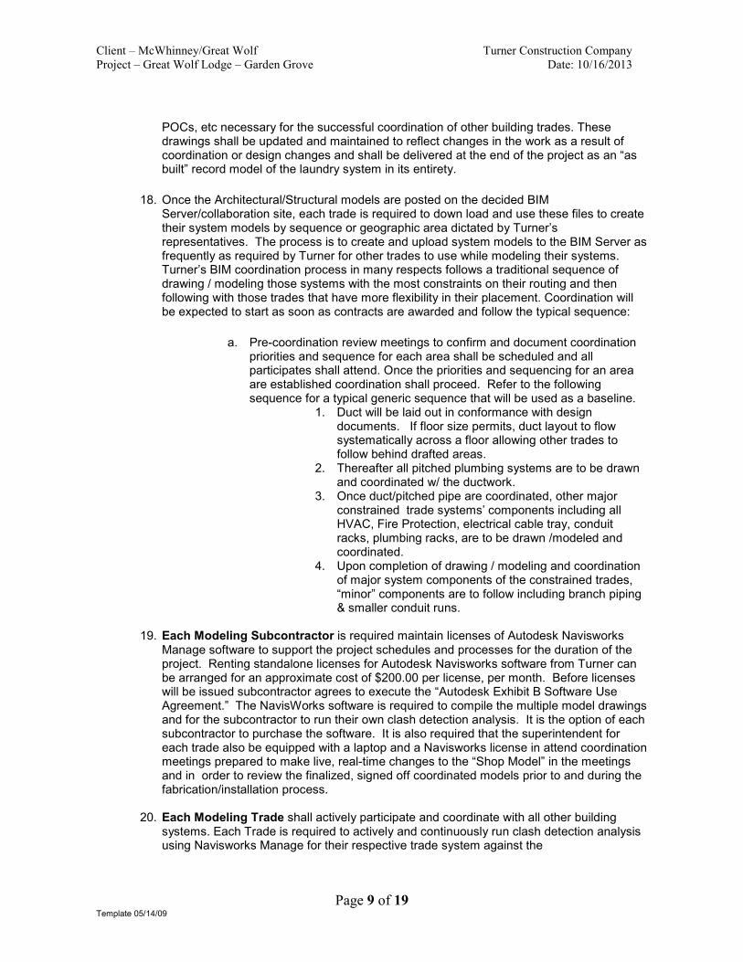
18. Once the Architectural/Structural models are posted on the decided BIM
Server/collaboration site, each trade is required to down load and use these files to create their system models by sequence or geographic area dictated by Turner’s representatives. The process is to create and upload system models to the BIM Server as frequently as required by Turner for other trades to use while modeling their systems. Turner’s BIM coordination process in many respects follows a traditional sequence of drawing / modeling those systems with the most constraints on their routing and then following with those trades that have more flexibility in their placement. Coordination will be expected to start as soon as contracts are awarded and follow the typical sequence:
a. Pre-coordination review meetings to confirm and document coordination
priorities and sequence for each area shall be scheduled and all participates shall attend. Once the priorities and sequencing for an area are established coordination shall proceed. Refer to the following sequence for a typical generic sequence that will be used as a baseline.
1. Duct will be laid out in conformance with design documents. If floor size permits, duct layout to flow systematically across a floor allowing other trades to follow behind drafted areas.
2. Thereafter all pitched plumbing systems are to be drawn and coordinated w/ the ductwork.
3. Once duct/pitched pipe are coordinated, other major constrained trade systems’ components including all HVAC, Fire Protection, electrical cable tray, conduit racks, plumbing racks, are to be drawn /modeled and coordinated.
4. Upon completion of drawing / modeling and coordination of major system components of the constrained trades, “minor” components are to follow including branch piping & smaller conduit runs.
19. Each Modeling Subcontractor is required maintain licenses of Autodesk Navisworks
Manage software to support the project schedules and processes for the duration of the project. Renting standalone licenses for Autodesk Navisworks software from Turner can be arranged for an approximate cost of $200.00 per license, per month. Before licenses will be issued subcontractor agrees to execute the “Autodesk Exhibit B Software Use Agreement.” The NavisWorks software is required to compile the multiple model drawings and for the subcontractor to run their own clash detection analysis. It is the option of each subcontractor to purchase the software. It is also required that the superintendent for each trade also be equipped with a laptop and a Navisworks license in attend coordination meetings prepared to make live, real-time changes to the “Shop Model” in the meetings and in order to review the finalized, signed off coordinated models prior to and during the fabrication/installation process.
20. Each Modeling Trade shall actively participate and coordinate with all other building
systems. Each Trade is required to actively and continuously run clash detection analysis using Navisworks Manage for their respective trade system against the
Client – McWhinney/Great Wolf Turner Construction Company
Project – Great Wolf Lodge – Garden Grove Date: 10/16/2013
Page 10 of 19 Template 05/14/09
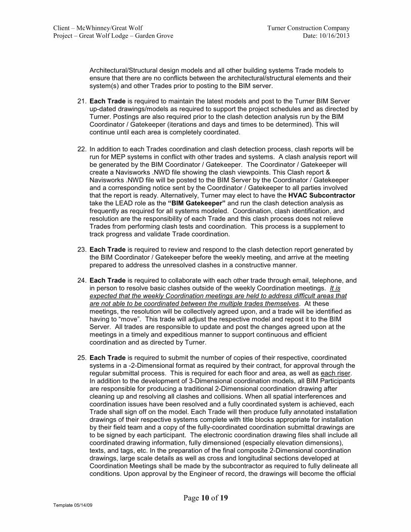
Architectural/Structural design models and all other building systems Trade models to ensure that there are no conflicts between the architectural/structural elements and their system(s) and other Trades prior to posting to the BIM server.
21. Each Trade is required to maintain the latest models and post to the Turner BIM Server up-dated drawings/models as required to support the project schedules and as directed by Turner. Postings are also required prior to the clash detection analysis run by the BIM Coordinator / Gatekeeper (iterations and days and times to be determined). This will continue until each area is completely coordinated.
22. In addition to each Trades coordination and clash detection process, clash reports will be
run for MEP systems in conflict with other trades and systems. A clash analysis report will be generated by the BIM Coordinator / Gatekeeper. The Coordinator / Gatekeeper will create a Navisworks .NWD file showing the clash viewpoints. This Clash report & Navisworks .NWD file will be posted to the BIM Server by the Coordinator / Gatekeeper and a corresponding notice sent by the Coordinator / Gatekeeper to all parties involved that the report is ready. Alternatively, Turner may elect to have the HVAC Subcontractor take the LEAD role as the “BIM Gatekeeper” and run the clash detection analysis as frequently as required for all systems modeled. Coordination, clash identification, and resolution are the responsibility of each Trade and this clash process does not relieve Trades from performing clash tests and coordination. This process is a supplement to track progress and validate Trade coordination.
23. Each Trade is required to review and respond to the clash detection report generated by the BIM Coordinator / Gatekeeper before the weekly meeting, and arrive at the meeting prepared to address the unresolved clashes in a constructive manner.
24. Each Trade is required to collaborate with each other trade through email, telephone, and in person to resolve basic clashes outside of the weekly Coordination meetings. It is expected that the weekly Coordination meetings are held to address difficult areas that are not able to be coordinated between the multiple trades themselves. At these meetings, the resolution will be collectively agreed upon, and a trade will be identified as having to “move”. This trade will adjust the respective model and repost it to the BIM Server. All trades are responsible to update and post the changes agreed upon at the meetings in a timely and expeditious manner to support continuous and efficient coordination and as directed by Turner.
25. Each Trade is required to submit the number of copies of their respective, coordinated systems in a -2-Dimensional format as required by their contract, for approval through the regular submittal process. This is required for each floor and area, as well as each riser. In addition to the development of 3-Dimensional coordination models, all BIM Participants are responsible for producing a traditional 2-Dimensional coordination drawing after cleaning up and resolving all clashes and collisions. When all spatial interferences and coordination issues have been resolved and a fully coordinated system is achieved, each Trade shall sign off on the model. Each Trade will then produce fully annotated installation drawings of their respective systems complete with title blocks appropriate for installation by their field team and a copy of the fully-coordinated coordination submittal drawings are to be signed by each participant. The electronic coordination drawing files shall include all coordinated drawing information, fully dimensioned (especially elevation dimensions), texts, and tags, etc. In the preparation of the final composite 2-Dimensional coordination drawings, large scale details as well as cross and longitudinal sections developed at Coordination Meetings shall be made by the subcontractor as required to fully delineate all conditions. Upon approval by the Engineer of record, the drawings will become the official
Client – McWhinney/Great Wolf Turner Construction Company
Project – Great Wolf Lodge – Garden Grove Date: 10/16/2013
Page 11 of 19 Template 05/14/09
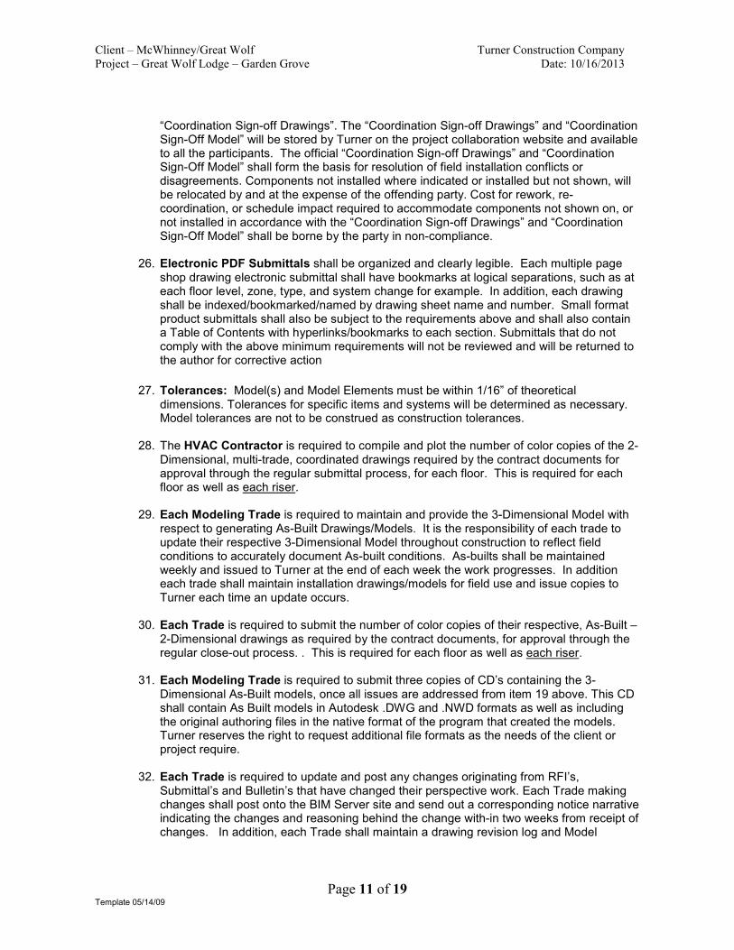
“Coordination Sign-off Drawings”. The “Coordination Sign-off Drawings” and “Coordination Sign-Off Model” will be stored by Turner on the project collaboration website and available to all the participants. The official “Coordination Sign-off Drawings” and “Coordination Sign-Off Model” shall form the basis for resolution of field installation conflicts or disagreements. Components not installed where indicated or installed but not shown, will be relocated by and at the expense of the offending party. Cost for rework, re-coordination, or schedule impact required to accommodate components not shown on, or not installed in accordance with the “Coordination Sign-off Drawings” and “Coordination Sign-Off Model” shall be borne by the party in non-compliance.
26. Electronic PDF Submittals shall be organized and clearly legible. Each multiple page shop drawing electronic submittal shall have bookmarks at logical separations, such as at each floor level, zone, type, and system change for example. In addition, each drawing shall be indexed/bookmarked/named by drawing sheet name and number. Small format product submittals shall also be subject to the requirements above and shall also contain a Table of Contents with hyperlinks/bookmarks to each section. Submittals that do not comply with the above minimum requirements will not be reviewed and will be returned to the author for corrective action
27. Tolerances: Model(s) and Model Elements must be within 1/16” of theoretical
dimensions. Tolerances for specific items and systems will be determined as necessary. Model tolerances are not to be construed as construction tolerances.
28. The HVAC Contractor is required to compile and plot the number of color copies of the 2-Dimensional, multi-trade, coordinated drawings required by the contract documents for approval through the regular submittal process, for each floor. This is required for each floor as well as each riser.
29. Each Modeling Trade is required to maintain and provide the 3-Dimensional Model with respect to generating As-Built Drawings/Models. It is the responsibility of each trade to update their respective 3-Dimensional Model throughout construction to reflect field conditions to accurately document As-built conditions. As-builts shall be maintained weekly and issued to Turner at the end of each week the work progresses. In addition each trade shall maintain installation drawings/models for field use and issue copies to Turner each time an update occurs.
30. Each Trade is required to submit the number of color copies of their respective, As-Built – 2-Dimensional drawings as required by the contract documents, for approval through the regular close-out process. . This is required for each floor as well as each riser.
31. Each Modeling Trade is required to submit three copies of CD’s containing the 3-Dimensional As-Built models, once all issues are addressed from item 19 above. This CD shall contain As Built models in Autodesk .DWG and .NWD formats as well as including the original authoring files in the native format of the program that created the models. Turner reserves the right to request additional file formats as the needs of the client or project require.
32. Each Trade is required to update and post any changes originating from RFI’s,
Submittal’s and Bulletin’s that have changed their perspective work. Each Trade making changes shall post onto the BIM Server site and send out a corresponding notice narrative indicating the changes and reasoning behind the change with-in two weeks from receipt of changes. In addition, each Trade shall maintain a drawing revision log and Model

Client – McWhinney/Great Wolf Turner Construction Company
Project – Great Wolf Lodge – Garden Grove Date: 10/16/2013
Page 12 of 19 Template 05/14/09
revision log in a format as directed by Turner for all revisions that occur post coordination sign off.
33. Each Trade shall actively participate in identifying and implementing quality control
procedures and processes to verify/validate quality of work on both the model and the installation of work in the field.
34. Each Trade shall share BIM metrics in collaboration with Turner. Each participant shall
actively participate and support efforts in measuring, identifying, collecting, and formatting information for BIM metrics to provide to Turner. See the following chart in figure 31A for an example of some Metrics expected but not limited to for the project.
Figure 31A Sample
Project Indicators Table
Indicators Tracked
(Yes/No)
Owners Name Frequency
Coordination Metrics:
Design durations:
Performance Against Schedule (PAS) for
development of Federated Model:
Yes
PAS for BIM activities relative to overall
design duration:
Yes
Model Conflicts List: Yes
Conflict Details: Yes
Conflict ROM cost savings: Yes
Conflict schedule avoidance: Yes
Construction Metrics:
Construction durations:
Performance Against Schedule (PAS): Yes
Overall Project Construction Execution: Yes
# of Request for Information (RFI): Yes
BIM related: Yes
Non-BIM related: Yes
# of Change Orders (CO):
BIM related: Yes
Non-BIM related: Yes
Amount of prefabrication done off site: Yes
BIM related: Yes
Non-BIM related: Yes
Subcontractor field (on site) headcount: Yes
Amount of waste/rework: Yes
BIM related: Yes
Subcontractor Error: Yes

Client – McWhinney/Great Wolf Turner Construction Company
Project – Great Wolf Lodge – Garden Grove Date: 10/16/2013
Page 13 of 19 Template 05/14/09
35. Each Trade is required to draw in a format that a 3rd
party individual can highlight and track progress of work thru selecting individual items in each trades model thru Navisworks.
36. Each Trade is required to attend separate meetings to review accessibility of equipment,
devices, panels, valves, etc. above ceiling with the owner, Architect, Engineer and Turner. Each Trade is responsible to provide and identify under separate drawing layer Access doors and Accessibility requirements for above listed items for maintenance purposes.
37. Change Order / Bulletin Process: The process for quantifying and correcting clashes
caused by a design change to a signed off and in-progress area is as follows: • Trade(s) that have work directly affected by the bulletin documents will take
the lead in drafting the revised 3-Dimensional layout, minimizing the clashes w/ other trades as much as possible. Revised layouts are to be drawn in an identifiable layer, labeled to match the respective bulletin.
• Once the work is drafted by the affected trade(s), a clash report is to be prepared by the BIM Coordinator / Gatekeeper w/ all latest posts. o While running the clash detection feature in Navisworks, the Coordinator /
Gatekeeper will turn on the ‘links view’ option and all clashes are labeled while navigating through the model.
o Coordinator / Gatekeeper will audit and report the clashes that are local to the area affected by the change documents, similar to the analysis of detected vs. reported clashes in preparation for weekly clash reports.
o This does not relieve Trades from their responsibilities to run clash detection, coordinate, and identify/resolve issues.
MISCELLANEOUS REQUIREMENTS A. Coordination is the responsibility of all Trades. Turner will call meetings, as required, which
contractors must attend. Failure to attend will result in work by the absent contractor on sheets reviewed at meeting being declared improperly coordinated and will require the contractor to relocate work as shown by Turner, or to field run the work not coordinated. No extra compensation will be paid to any contractor for relocating any duct, pipe, conduit, or other material that has been installed without proper coordination between all the contractors and the trades involved. If any improperly coordinated work, or work installed that is not in accordance with the approved coordination composites, necessitates additional work by other contractors, the cost of such additional work shall be assessed to the contractor responsible as determined by Turner. Errors in coordination will be resolved by the contractor at his own expense. Where agreements cannot be reached, Turner will furnish a resolution. The contractor will bear the expense of said resolution.
B. All work on the coordination drawings (including 3D models) shall be performed by competent
draftsmen in a clear legible manner utilizing standard industry conventions. All trade contractors shall be responsible for providing their coordination drawing files according to the established coordination schedule. It is the responsibility of each contractor to supply a sufficient number of draftsmen so as not to delay the BIM 3-Dimensional coordination process and shop drawing submittals.
C. Coordination drawings are not to be construed as and not to relieve each contractor from their
shop drawing obligations required under the project specifications, and are distinctly separate from the requirements to provide final “As-Built” drawings.
D. All files supplied by Turner will be as AutoDesk .dwg file format and be readable by other
trades’ CAD system and NavisWorks. Being ‘readable’ means the ability to open a file without

Client – McWhinney/Great Wolf Turner Construction Company
Project – Great Wolf Lodge – Garden Grove Date: 10/16/2013
Page 14 of 19 Template 05/14/09
any errors (such as prox, xref resolution, geometry error, etc) and with objects, layers, and other file properties remaining intact. In addition all dwg files shall be saved down to the lowest common version which is 2010 file format.
E. The trade contractors are responsible for providing 3-Dimensional solid or surface models (not
line & wireframe models) that represents the actual dimensions of the trade system elements and the equipment that will be installed.
F. It is critical that all trade contractors use a mandated file naming convention for their CAD file’s
name to track the version and date by each trade. Turner will provide the detailed file naming convention to all MEP contractors. An example would be as follows: “Project_Responsibility_Phase_Trade_Floor_Area_Version_Date” Any files that do not follow the file naming convention will be deleted and removed from the server at any time without any notification.
G. All trade subcontractor’s drawing and model files shall be based on an origin point provided by
Turner. The cost of any changes required by the Trade Contractor to their drawings or models due to the use of an unauthorized origin shall be borne by the trade contractor.
Minimum 3D Modeling Coordination Scope (As Applicable)
Concrete � Edge of slab Plan � Pre-cast panelized structures � Concrete floors, curbs, walls, tunnels, and sumps � Cast in place concrete on Metal Deck � Balconies � Ramps � Slab depressions � Roof openings � Smoke vents � Stairs and fire escapes � Stair balustrades � Slopes � Cold joints � Post tension cables � Scaffold and shoring plans
Structural Steel
� 3D Model of Structural steel shop drawings � Primary Steel � Connection details � Bent Plate � Secondary support steel at roof and deck penetrations as required by contract details � Permanent and Temporary columns, beams, supports, braces, kickers, and etc � Openings, stairs, and landings � Decking
Site Utilities
� Storm Drain � Gas � Cold Water � Fire Water
� Meters (with required clearances)
� Drains � Yard Boxes � Thrust Blocks � Cleanouts
� Manholes � Backflow Devices � Stormceptor � Valves � Hydrant Locations

Client – McWhinney/Great Wolf Turner Construction Company
Project – Great Wolf Lodge – Garden Grove Date: 10/16/2013
Page 15 of 19 Template 05/14/09
� Catch Basins and Tanks
� Pipe Detention System
� Sleeves/penetrations vertical and horizontal
� Layout Points and POCs
Fire Sprinkler
� All Mains � Branch Lines � Drops / heads (with required clearances) � Risers (with sleeves) � Gravity Supports � Seismic Bracing and Anchors � Equipment (with required clearances) � Access Abstractions � Sleeves/penetrations vertical and horizontal to be incorporated into composite trade submittal
by Plumbing contractor � Point Loads of all gravity loads to be incorporated into composite trade submittal by HVAC
contractor (Healthcare projects only or as stipulated in contract documents) � Housekeeping pads to be incorporated into composite submittal by HVAC contractor � Backing � Equipment supports � RCP layout with ceiling devices to be incorporated into a composite trade submittal by Drywall
and acoustic ceiling contractor � All support elements and braces
Plumbing
� All Systems, Equipment, & Appurtenances (Waste, Vent, Drain, Storm, Condensate, Gas, Hot and Cold Water etc.)
� Riser/Shafts (with seismic & supports & sleeves) � Valves in both positions or as an abstraction � Gravity Hangers � Seismic Bracing and anchors � Access Abstractions � Insulation � In wall � Equipment with POCs and with required clearances � Sleeves/penetrations vertical and horizontal to be incorporated into composite trade submittal
by Plumbing contractor � Point Loads of all gravity loads to be incorporated into composite trade submittal by HVAC
contractor (Healthcare projects only or as stipulated in contract documents) � Housekeeping pads to be incorporated into composite submittal by HVAC contractor � Backing � Equipment supports � RCP layout with ceiling devices to be incorporated into a composite trade submittal by Drywall
and acoustic ceiling contractor � All support elements
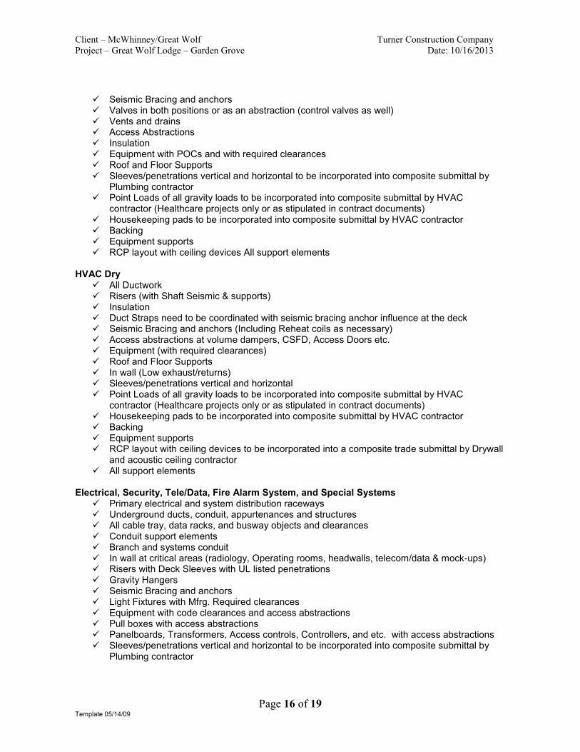
HVAC Wet
� All piping � Risers (with Shaft Seismic & supports or Sleeves) � Gravity Supports, hangers, anchors, guides, embeds, and inserts
Client – McWhinney/Great Wolf Turner Construction Company
Project – Great Wolf Lodge – Garden Grove Date: 10/16/2013
Page 16 of 19 Template 05/14/09
� Seismic Bracing and anchors � Valves in both positions or as an abstraction (control valves as well) � Vents and drains � Access Abstractions � Insulation � Equipment with POCs and with required clearances � Roof and Floor Supports � Sleeves/penetrations vertical and horizontal to be incorporated into composite submittal by
Plumbing contractor � Point Loads of all gravity loads to be incorporated into composite submittal by HVAC
contractor (Healthcare projects only or as stipulated in contract documents) � Housekeeping pads to be incorporated into composite submittal by HVAC contractor � Backing � Equipment supports � RCP layout with ceiling devices All support elements
HVAC Dry � All Ductwork � Risers (with Shaft Seismic & supports) � Insulation � Duct Straps need to be coordinated with seismic bracing anchor influence at the deck � Seismic Bracing and anchors (Including Reheat coils as necessary) � Access abstractions at volume dampers, CSFD, Access Doors etc. � Equipment (with required clearances) � Roof and Floor Supports � In wall (Low exhaust/returns) � Sleeves/penetrations vertical and horizontal � Point Loads of all gravity loads to be incorporated into composite submittal by HVAC
contractor (Healthcare projects only or as stipulated in contract documents) � Housekeeping pads to be incorporated into composite submittal by HVAC contractor � Backing � Equipment supports � RCP layout with ceiling devices to be incorporated into a composite trade submittal by Drywall
and acoustic ceiling contractor � All support elements
Electrical, Security, Tele/Data, Fire Alarm System, and Special Systems
� Primary electrical and system distribution raceways � Underground ducts, conduit, appurtenances and structures � All cable tray, data racks, and busway objects and clearances � Conduit support elements � Branch and systems conduit � In wall at critical areas (radiology, Operating rooms, headwalls, telecom/data & mock-ups) � Risers with Deck Sleeves with UL listed penetrations � Gravity Hangers � Seismic Bracing and anchors � Light Fixtures with Mfrg. Required clearances � Equipment with code clearances and access abstractions � Pull boxes with access abstractions � Panelboards, Transformers, Access controls, Controllers, and etc. with access abstractions � Sleeves/penetrations vertical and horizontal to be incorporated into composite submittal by
Plumbing contractor
Client – McWhinney/Great Wolf Turner Construction Company
Project – Great Wolf Lodge – Garden Grove Date: 10/16/2013
Page 17 of 19 Template 05/14/09
� Point Loads of all gravity loads to be incorporated into composite submittal by HVAC contractor (Healthcare projects only or as stipulated in contract documents)
� Housekeeping pads to be incorporated into composite submittal by HVAC contractor � Backing � Equipment supports � RCP layout with ceiling devices to be incorporated into a composite trade submittal by Drywall
and acoustic ceiling contractor � All support elements
Food Service Equipment
� Equipment, trim, and appurtenances with POC’s, code clearances, and access abstractions � Valves in both positions or as an abstraction � Gravity supports, hangers, anchors, embeds, and inserts. � Seismic Bracing and supports, hangers, anchors, embeds, and inserts. � Access and clearance abstractions � Insulation � In wall � Floor and ceiling supports, and equipment pads � Sleeves, penetrations, and block outs both vertical and horizontal to be incorporated into
composite submittal by Plumbing contractor � Point Loads of all gravity loads to be incorporated into composite submittal by HVAC
contractor ( as required by the Structural Engineer) � Housekeeping pads and curbs to be incorporated into composite submittal by HVAC
contractor � Backing � Equipment supports, anchorage, embeds, inserts, etc. � RCP layout with ceiling devices and access panels to be incorporated into a composite
submittal by Drywall and acoustic ceiling contractor � All support elements and braces � Islands, counters, curbs, and bases � Closure trim � Architectural and structural openings
Drywall / Metal Framing
� Floor Plan validate and maintain � All Vertical and Horizontal shafts with studs � Full Height walls with studs, top track, kickers, and stickers/z-clips � Partial height with studs walls with kickers � Soffits with studs, joists, and kickers � Identify rated walls (by color or pattern) as well as horizontal shafts & wall types � King Studs � Bent plate to exterior framing/curtain wall � Light Coves � Doors and openings in walls (including roll up door openings and framing) � Backing � Hand Rails � Corner Guards � RCP validate and maintain � RCP layout with ceiling devices to be incorporated into a composite trade submittal by Drywall
and acoustic ceiling contractor � Identify and detail Pre-rock (interference walls) and leave-out walls � Exit passageways (with required clearances) � Box Headers and Penetrations

Client – McWhinney/Great Wolf Turner Construction Company
Project – Great Wolf Lodge – Garden Grove Date: 10/16/2013
Page 18 of 19 Template 05/14/09
� Curtain Tracks � Compression posts (coordinate with obstructions to provide a constructible system) � Scaffold plans
Miscellaneous Steel � Toilet Partitions � Roll Up Door Supports � Low Wall tube steel � Floor Penetration Support Steel � Equipment Support Steel � Stairs � Elevator Shaft Steel � Secondary support steel at roof and deck penetrations as required by contract details � Openings, stairs, and landings � Permanent and Temporary columns, beams, supports, braces, kickers, and etc
Unistrut
� All major components � All support elements � All attachments
Pneumatic Tube (Laundry & Water Park)
� All tube � Gravity supports � Seismic bracing and anchors � Equipment (with access abstractions as necessary) � Sleeves/penetrations vertical and horizontal to be incorporated into composite submittal by
Plumbing contractor � Point Loads of all gravity loads to be incorporated into composite submittal by HVAC
contractor (Healthcare projects only or as stipulated in contract documents) � Housekeeping pads to be incorporated into composite submittal by HVAC contractor � Backing � Equipment supports � RCP layout with ceiling devices to be incorporated into a composite trade submittal by Drywall
and acoustic ceiling contractor � All support elements
Acoustic Ceilings
� Compression posts (coordinate with obstructions to provide a constructible system) � RCP layout with ceiling devices to be incorporated into a composite trade submittal by Drywall
and acoustic ceiling contractor � RCP layout validate and maintain � Backing, attachment angles, and trapezes
Interior Millwork and Casework
� Casework � Supports, anchors, braces, and backing � Rough carpentry � Cutouts and openings � Curbs
Curtain Wall
� All misc. structural elements (wind braces, imbeds, kickers, supports, etc)

Client – McWhinney/Great Wolf Turner Construction Company
Project – Great Wolf Lodge – Garden Grove Date: 10/16/2013
Page 19 of 19 Template 05/14/09
� Complete model of assembly (exterior, panels, etc) Additional Clarifications:
1. It is intended, unless otherwise noted that all the elements above be modeled in 3D and
issued in an AutoCAD DWG and Navisworks NWD 2012 format or format as directed by Turner.
2. It is also the intent to provide the client with a fully integrated and coordinated 3D model. All
trades shall be responsible to coordinate their scope with all other building elements. 3. All abstractions of building/trade elements shall be reviewed and approved by Turner prior to
proceeding with work.
4. All Mockups shall be fully detailed in 3D. All building systems shall be fully developed including but not limited to all framing, all MEPT systems and devices, finishes, lighting, Fire life safety systems, fire safeing, fixtures, etc.
5. The process will involve an FTP site for electronic drawings distribution. The specific process,
file naming, and schema shall to be determined.
6. All Subcontractors shall provide model for all Structural penetrations under their responsibility for incorporation into a composite submittal package by the Plumbing contractor or as directed by Turner.
7. Subcontractors shall provide models for all Point Loads and all gravity loads under their
responsibility for incorporation into a composite submittal package by the HVAC Subcontractor or as directed by Turner.
8. Subcontractors shall provide models of Housekeeping pads under their responsibility for
incorporation into a composite submittal package by the HVAC Subcontractor or as directed by Turner.
9. Subcontractors shall provide models of all ceiling devices and access panels in or on hard lids
under their responsibility for incorporation into a composite submittal package by the Drywall Subcontractor or as directed by Turner.
10. Subcontractors shall provide models of all ceiling devices and access zones in or on acoustic
ceilings under their responsibility for incorporation into a composite submittal package by the acoustic ceilings Subcontractor or as directed by Turner.


![BIM PROJECT EXECUTION PLAN - Penn State Engineering€¦ · [project title] [date] building information modeling project execution plan version 1.05 1 section a: bim project execution](https://static.fdocuments.in/doc/165x107/5ae395557f8b9a595d8e9d18/bim-project-execution-plan-penn-state-project-title-date-building-information.jpg)


