.$:B5B36&'5 B180 B 3DJH RI - Missouri Public Service ... · 7.1.2 Crack measurements ... • ACI...
77
KENTUCKY AMERICAN WATER RICHMOND ROAD STATION FILTER BUILDING PRELIMINARY STRUCTURAL AND MECHANICAL EVALUATION Prepared by American Water Works Service Company Corporate Engineering 3906 Church Road Mt Laurel, NJ 08054 December 2012 KAW_R_PSCDR1_NUM004_091714 Page 1 of 77
-
Upload
duongkhanh -
Category
Documents
-
view
226 -
download
0
Transcript of .$:B5B36&'5 B180 B 3DJH RI - Missouri Public Service ... · 7.1.2 Crack measurements ... • ACI...

KENTUCKY AMERICAN WATER RICHMOND ROAD STATION
FILTER BUILDING
PRELIMINARY STRUCTURAL AND MECHANICAL EVALUATION
Prepared by American Water Works Service Company
Corporate Engineering 3906 Church Road
Mt Laurel, NJ 08054 December 2012
KAW_R_PSCDR1_NUM004_091714 Page 1 of 77

1 Table of Contents 2 EXECUTIVE SUMMARY ............................................................................................................. 3
3 INTRODUCTION ....................................................................................................................... 6
3.1 PURPOSE OF ASSESSMENT .............................................................................................. 6
3.2 SCOPE OF INVESTIGATION............................................................................................... 6
3.2.1 Methods and Techniques ........................................................................................ 6
4 EVALUATION AND ASSESSMENT CRITERIA .............................................................................. 8
4.1.1 DESCRIPTION OF DISTRESS ...................................................................................... 9
4.1.2 MATERIAL PROPERTIES .......................................................................................... 10
4.1.3 LOADING CONDITIONS/DESIGN CRITERIA ............................................................. 11
5 DESCRIPTION OF STRUCTURE ................................................................................................ 12
5.1 GENERAL ........................................................................................................................ 12
5.2 DATES OF CONSTRUCTION, ALTERATION AND REPAIR ................................................. 13
5.3 COLLECTED DATA........................................................................................................... 14
6 DISCUSSION OF SITE VISIT ..................................................................................................... 15
6.1 OBSERVED CONDITIONS ................................................................................................ 15
6.2 OVERALL RATING OF THE STRUCTURE .......................................................................... 25
7 OFFICE ANALYSIS ................................................................................................................... 36
7.1 TESTING RESULTS .......................................................................................................... 36
7.1.1 Rebound Hammer ................................................................................................. 36
7.1.2 Crack measurements ............................................................................................. 37
7.1.3 Readings on steel pipe hangers. ............................................................................ 37
7.2 COMPUTATIONAL ANALYSIS ......................................................................................... 39
7.3 CODE CONFORMANCE ................................................................................................... 39
7.4 MECHANICAL COMPONENTS ........................................................................................ 39
8 CONCLUSIONS AND RECOMMENDATIONS ........................................................................... 41
8.1 FILTER GALLERY ............................................................................................................. 41
8.1.1 Floor slab ............................................................................................................... 41
8.1.2 Concrete beams ..................................................................................................... 41
8.1.3 Concrete walls ....................................................................................................... 42
1
KAW_R_PSCDR1_NUM004_091714 Page 2 of 77

8.1.4 Bottom Slab ........................................................................................................... 43
8.1.5 Steel Hanger Supports for the 36” Cast Iron Pipe ................................................. 43
8.1.6 Steel Pipe Supports ................................................................................................ 43
8.1.7 Steel ladder ............................................................................................................ 43
8.2 FILTER TANKS ................................................................................................................. 44
8.2.1 Top slab ................................................................................................................. 44
8.2.2 Concrete walls ....................................................................................................... 45
8.3 STEEL FRAME BUILDING ................................................................................................ 46
8.4 MECHANICAL COMPONENTS INCLUIDING PIPING, VALVES AND OPERATORS ............. 46
8.5 SHORT TERM REMEDIATION ......................................................................................... 46
8.6 COST ESTIMATES ........................................................................................................... 48
Figures Figure 6.1.1 Overall Rating. Filters – Exterior Top Slab EL 993.33 Figure 6.1.2 Overall Rating. Pipe Gallery – Top Slab and beams EL 994.18 Figure 6.1.3 Overall Rating. Pipe Gallery – Bottom Slab EL 982.60 Figure 6.1.4 Overall Rating. Filters – Exterior Walls – North Elevation Figure 6.1.5 Overall Rating. Filters – Exterior Walls – South Elevation Figure 6.1.6.a,b Overall Rating. Pipe Gallery – Walls – South Side Figure 6.1.7.a,b Overall Rating. Pipe Gallery – Walls – North Side
Tables Table 6.2 Condition Assessment of the Filter Tank
Table of Appendices Appendix A Structural Calculations Appendix B Recommended Repair Products
2
KAW_R_PSCDR1_NUM004_091714 Page 3 of 77

2 EXECUTIVE SUMMARY The Richmond Road Filter Building and associated structures (Filters and Clearwell) was originally constructed in 1924 with Building and Filter modifications in 1937, 1938 and 1953. There are also references to alterations/modifications to the structure and piping which occurred in 1971 and 2001. The rating of the structure and its associated components varies based on the date of construction. In general, the filter gallery and exterior walls between filters 11 to 22 (1924 to 1938) can be classified as poor to severe condition. These filters and the associated mechanical piping and equipment need to undergo extensive repairs and rehabilitation. On the other hand, Filters 23-26 (1953 Construction) including the associated mechanical components can be rated as fair/satisfactory. From a structural standpoint, the most critical deterioration has occurred in the operating floor slab located above the headwork’s area. This is associated with the 1924 construction period and is manifested by exposed and deteriorated rebar in the floor and floor slab beams. Fifty-eight (58%) of the concrete beams in this area have experienced a loss of concrete cover over the reinforcing bars exposing the bars to corrosion and deterioration. Beam repair is critical to avoid further deterioration that would compromise the structural integrity of the beams. Non structural concrete cracks were noted throughout the filter tank walls in the filter gallery area. Most of these cracks were sources of leakage from the filters into the gallery area. These leaks add to the humidity in the filter gallery area and in combination with chlorine gases form acidic and corrosive conditions as noted on the mechanical structures. Most of the cracks are found in the area associated with Filters 11 to 22 (older section) as compared to the 1953 section of Filters 23-26. However, there were also cracked walls associated with the newer filters and are also in need of repair. Recommendations for crack repair include cleaning, epoxy injection and surface sealing. After finishing the crack repair, a corrosion resistant protective coating is recommended to prevent further deterioration. An application procedure and recommendations product listing is presented in the appendix of the report. The condition of the top slabs for filters 15, 16, 17, 22 and 23 are classified as poor/severe. These structures are located outside of the building and are subject to weather and freeze/thaw conditions. Clear signs of weathering were noted as evidenced by scaling, exposed rebar, hollow zones noted through rebound hammer testing, and visual cracks. Additional testing of the top slabs will be required to verify the extent of deterioration. In certain locations, complete replacement of the top slab may be required. The top slabs on the remaining filters (11, 13, 18, 21, 24, 25, and 26) are in satisfactory condition and do not require repair. The exterior concrete walls associated with the filters also show signs of deterioration and distress. In particular, the exterior walls associated with Filters 20 and 22 show signs of cracking, staining and leaks which are indicative of severe distress. Rebar exposure and corrosion is also evident for these filters. The remaining filters are either
3
KAW_R_PSCDR1_NUM004_091714 Page 4 of 77

buried below ground (12 & 14) or are covered with a brick facade (filters along the southern side of building). Those with the brick facade showed clear signs of moisture penetration as well as wet spots accumulated along the base. These are indications of cracks and water penetration. Removal of the brick would be required to evaluate the degree of cracking and need for repair. In addition to the concrete structures, steel pipe hangers and supports are in need of repair/replacement. In particular, the pipe hangers for the 36 inch raw water pipe are severely corroded and are in need of replacement. Besides a significant loss of steel, the pipe hangers are pitted and show signs of severe corrosion. The overall condition of the mechanical components of the filter gallery is rated as poor/fair. The valve operators have been largely changed out over the years but are still in need of constant repair due to the corrosive environment. The valves that service the filters are very old dating back to the original construction in the 1930’s and are largely original equipment. Their replacement will be required over time. Due to the severe space constraints associated with the gallery, their replacement will be very difficult and, in some cases, may require excavation of the operating floor slab for access. In addition to the filter valves and operators, severe corrosion of the piping and joints has occurred throughout the gallery due to moisture and acidic conditions. Of particular concern are the pipe joints which have corroded bolts and associated hardware. Many of these joints need to be completely replaced. Furthermore, the piping in the gallery is also showing signs of corrosion and may require sections to be replaced. A more detailed structural analysis is required to determine the exact loss of pipe material. Access to the valve gallery is poor and the ability to service the equipment is difficult at best. The piping gallery is congested with valves, operators, pipe and pipe supports along with electrical equipment and conduits required for the valve operators. This mix of equipment and materials represents a severe challenge for the maintenance and repair staff. Ingress and egress is difficult depending on the location and may represent a hazard to the staff attempting to repair equipment. Extreme caution is required whenever equipment is removed or added to this space. Replacement of existing valves, operators and associated components will prolong the useful life of the Filter Building. However, the longevity of any repairs needs to be weighed against the costs and overall functionality of the structure. A review of the structural deficiencies of the filter building raises serious concerns as to the efficacy of replacing piping, valves, operators and associated components with a life expectancy of less than 20-25 years. In addition, the replacement of the existing equipment will only perpetuate the potential hazard associated with the piping gallery and in no way correct or improve it. Furthermore, any repair may reveal deficiencies undiscovered to date further questioning the cost effectiveness of repair versus replacement. In conclusion, serious consideration should be given to replacement of the existing filters. While consideration is being given to repair or replacement of the existing filters, there are a number of short term repair recommendations. Included among these are: repair and reinforcement of 10 concrete beams rated critical, 6 concrete beams rated serious and 8 concrete beams rated poor; recoating the concrete roof slab at selected locations, applying a corrosion inhibitor, reestablish cover over the exposed rebar and applying a
4
KAW_R_PSCDR1_NUM004_091714 Page 5 of 77

corrosion resistant protective coating.; and replace steel hanger supports for the 36 inch cast iron pipe.
5
KAW_R_PSCDR1_NUM004_091714 Page 6 of 77

3 INTRODUCTION
This report summarizes the findings of the inspection performed by American Water Corporate Engineering of the Filter Building at Richmond Road Station in Lexington, Kentucky.
3.1 PURPOSE OF ASSESSMENT
This evaluation of the structural integrity of the Richmond Road Filter Building is intended to provide a preliminary assessment of the existing structure for potential rehabilitation and /or replacement. The evaluation process is intended to assess the deterioration of the concrete structure due to weather exposure on the exterior, as well as interior structural damage or distress as a result of potential foundation settlement, abrasion, fatigue effects, chemical attack, and/or weathering.
3.2 SCOPE OF INVESTIGATION
The scope of this work includes: review of available documents, site inspection, preliminary analysis and preliminary evaluation and recommendations. This inspection was performed in accordance with the standards of the
• ASCE 11-99. Guideline for structural condition assessment of existing structures. • ASCE 7-05. Minimum Design Loads for Buildings and other structures. • ACI201.1R-08. Guide for conducting a visual inspection of concrete in service. • ACI 224.1R-07. Causes, evaluation, and repair of cracks in concrete. • ACI 364.1R-07. Guide for evaluation of concrete structures before rehabilitation. • ACI 350-06. Code Requirements for Environmental Engineering Concrete. • AISC Steel Construction Manual. 13th Edition.
3.2.1 Methods and Techniques
An investigation of the Building and Filters is intended to document the nature and extent of observed conditions and to identify any problems associated with the critical components and elements. Attention will focus on the connections, support structures, areas of abrupt geometric changes and areas in the structure where load concentrations occur. Areas of spalling, cracking, exposed re-bar, pitting, deterioration, and/or distress will be observed, recorded and measured where accessible.
3.2.1.1 Data collection and documentation A comprehensive review of available plans, specifications, construction records or other related documents was performed. The purpose of this review is to understand the
6
KAW_R_PSCDR1_NUM004_091714 Page 7 of 77

critical design details of the filters and building, the load paths and elements, and the presence of any unusual features
3.2.1.2 Testing Non destructive testing were performed on the concrete including rebound hammer testing to estimate compressive strength of the concrete, measurement of crack length and width using a micrometer and measurement of rebar destruction.
3.2.1.3 Structures to be evaluated
• Filter building (steel frame and masonry structure) • Pipe gallery ( bottom slab, interior walls, top slab and roof beams) • Filters (exterior walls, top slab).
7
KAW_R_PSCDR1_NUM004_091714 Page 8 of 77

4 EVALUATION AND ASSESSMENT CRITERIA The most common causes of concrete deterioration include alkali-aggregate reactions; unsound cement, contaminated water and aggregates; sulfate attack; freezing and thawing; fatigue; damage for accidents, poor construction practices, construction overloads, errors in design and detailing, externally applied loads. Some of these causes are directly related to deterioration of the reinforcing steel embedded in the concrete. A condition assessment rating of each facility, structure, and element group is provided to aid in establishing the priority of the recommended follow-up actions. The condition assessment ratings are described in Table 4.1. Assessment
Rating Description
Not inspected
Good No problems or only minor problems noted. Structural elements may show some very minor deterioration, but no overstressing observed.
Satisfactory Minor to defects and deterioration observed, but no overstressing observed.
Fair All primary structural elements are sound; but minor to moderate defects and deterioration observed. Localized areas of moderate to advanced deterioration may be present but do not significantly reduce the load bearing capacity of the structure.
Poor Advanced deterioration or overstressing observed on widespread portions of the structure, but does not significantly reduce the load carrying capacity of the structure.
Serious Advanced deterioration, overstressing, or breakage may have significantly affected the load bearing capacity of primary structural elements. Local failures are possible and loading restrictions may be necessary.
Critical Very advanced deterioration, overstressing, or breakage has resulted in localized failure(s) of primary structural elements. More widespread failures are possible or likely to occur and load restrictions should be implemented as necessary.
Table 4.1 Condition Assessment Rating
8
KAW_R_PSCDR1_NUM004_091714 Page 9 of 77

4.1.1 DESCRIPTION OF DISTRESS
4.1.1.1 Cracking A crack is a complete or incomplete separation, of either concrete or masonry, into two or more parts produced by breaking or fracturing. Cracking of concrete should be reported based on crack widths and type of crack. Crack patterns include checking, craze cracks, D-cracks, diagonal cracks, hairline cracks, longitudinal cracks, map cracking, shrinkage cracking, random cracks, temperature cracking and transverse cracks. Table 4.1.1.1 provides the tolerable crack width in accordance to ACI 224R.
Exposure condition Tolerable crack width (in) Dry air or protective membrane 0.016
Humidity, moist air, soil 0.012 Water retaining structures 0.004
Table 4.4.1.1 Tolerable crack width for reinforced concrete.
4.1.1.2 Distress Concrete distress will be reported based on visual observations of the deterioration. Deterioration is a physical manifestation of failure of a material caused by environmental or internal autogenous influences of rock and hardened concrete as well as other materials or decomposition of material during either testing or exposure to service. Common manifestations of distress include: Chalking, curling, deflection, deformation, delamination, disintegration, dusting, efflorescence, exfoliation, exudation, joint deficiencies, joint fault, mortar flaking, peeling, popout, scaling, spall.
4.1.1.3 Textural features and phenomena relative to their development Textural features include: air void, blistering, bugholes, cold joint, discoloration, honeycomb, sand pocket, segregation, staining, stalactite.
9
KAW_R_PSCDR1_NUM004_091714 Page 10 of 77

4.1.2 MATERIAL PROPERTIES
4.1.2.1 Concrete From the 1924 Record Drawings, all concrete was mixed in the proportion 1:2:4 and all floor slabs and beams were poured monolithically. However the specification doesn’t mention if the proportion is by weight or volume. If the proportions are based on weight we still need to know the required water cement ratio. In the past, the design of concrete mixes has been done by empirically based weight ratios of the primary constituents (cement: sand: coarse aggregate and water). The proportions were chosen based on experience and job specific objectives and limitations. According to the literature, a concrete mix in proportion 1:2:4 corresponds to a concrete compressive strength equivalent to 3,500 psi.
4.1.2.2 Reinforcing steel From the 1924 Record Drawings, reinforcement was of the intermediate grade of steel with all splices in reinforcing bars at least 40 diameters. When the American Society for Testing and Materials (ASTM) first adopted their Standard for Billet-Steel Reinforcement Bars in 1911, there were three grades of deformed bars - Structural Steel Grade (specified yield strength, fy= 33 ksi), Intermediate Grade (fy = 40 ksi) and Hard Grade (fy = 50 ksi). Today ASTM A615 recognizes four grades of deformed reinforcing bars, Grade 40, Grade 60, Grade 75 and the newly added Grade 80. Therefore the specify yield stress of steel, fy =40,000 psi and fs= 16,000 psi.
10
KAW_R_PSCDR1_NUM004_091714 Page 11 of 77

4.1.3 LOADING CONDITIONS/DESIGN CRITERIA The design review was based using the Strength Design Method. Filter gallery: Slabs and beams were reviewing to support the following dead and live loads:
• Selfweight of elements (D) • 40 psf superimposed load (mechanical duct allowance, insulation,etc) (D) • 150 psf over operating floor slab (L) • 7.2 kips concentrated load @ beam midspan due to 36” Cast Iron Pipe (L) • 5.3 kips concentrated load @ beam midspan due to 30” Cast Iron Pipe (L) • 6.5 kips concentrated load @ beam midspan due to 30” Cast Iron Pipe (L)
Walls were reviewing to support the following hydrostatic and soil pressure:
• Weight of gravel: 152 pcf, h= 1.75 ft (H) • Weight of sand: 132 pcf, h= 2.50 ft (H) • Weight of water: 62.4pcf, h= 2.50 ft (F)
Filter tanks: Slabs and beams were reviewing to support the following dead, live loads and snow loads:
• Selfweight of elements (D) • 40 psf superimposed load (mechanical duct allowance, insulation,etc) (D) • 100 psf over roof slab (RL) • 30 psf (S)
Walls were reviewing to support the following hydrostatic and soil pressure:
• Weight of gravel: 152 pcf, h= 1.75 ft (H) • Weight of sand: 132 pcf, h= 2.50 ft (H) • Weight of water: 62.4pcf, h= 2.50 ft (F) • Soil pressure: completely buried (Filters 12, 14 ) (H) • Soil pressure: partially buried ( Filters 16, 18, 20, 22) (H)
D= Dead Load, L= Live Load, RL= Roof Live Load, S= Snow Load, F= Hydrostatic Load H= Soil Load. The design review did not include any consideration or allowance for seismic or wind loads.
11
KAW_R_PSCDR1_NUM004_091714 Page 12 of 77

5 DESCRIPTION OF STRUCTURE
5.1 GENERAL
The Filter Building is located at Richmond Road Station in Lexington, Kentucky. The substructure of the building was constructed in 1924 and consists of a 62’ W x 106’ L x 12’ H clearwell concrete basin with a surface area of 6,572 SF. The clearwell is 600,000 Gal. capacity and it is completely buried. The superstructure consists of a series of sixteen (16) concrete box filters, each 20’ L x 17’ W x 8.5’ H, a pipe gallery and a steel frame with brick veneer on top of the concrete filters. (Refer to Figure No.1). The total dimensions of the structure are 62’ W x 144’L with a surface area of approx 8,900 SF.
Figure No.1. Typical section of the structure.
According to the record drawings even filters are located in the North side (Filters 12 to 26) and uneven filters in the South (Filters 11 to 25). A pipe gallery was constructed in the central area of the building and approximately 80% of maintenance labor is spent repairing valves in it. The filter pipe gallery is extremely congested which makes working in this area difficult. Inadequate ventilation and dehumidification has accelerated the deterioration of the piping and valve actuators. Additionally, there is visible cracking of the filter walls and leaking in the filter gallery.
Steel Frame w/brick veneer
Filter Tanks/ Pipe gallery
Clearwell Basin
12
KAW_R_PSCDR1_NUM004_091714 Page 13 of 77

5.2 DATES OF CONSTRUCTION, ALTERATION AND REPAIR
According to the record drawings the concrete filters were constructed at different stages as follow (Refer to Figure No.2):
Filters 11 to 14 and temporary wood building 1924 Filters 15 to 20 and steel frame building 1937 Filters 21 to 22 and steel frame building 1938 Filters 23 to 25 and steel frame building 1953 There also references of some alterations/modifications during the service life of the structure as follow: RRS Renovation 1971 Site Piping Modifications 2001 1953 1938 1937 1924
Figure No.2. Dates of construction. Filter building Plan View.
In 2003, a dehumidifier was installed in the filter building to try to control the humidity in the filter gallery. However, there is still a considerable amount of moisture in the filter gallery. It is unknown how much of the moisture in the filter gallery is due to air flow conditions and pipe sweating and how much is related to leaking pipes and filters. There also appear to be leaks between the filter gallery and the chlorine contact chamber that is below the filters as there is a chlorine smell in the room. Expedited corrosion of equipment and piping could be a result of the chlorine.
13
KAW_R_PSCDR1_NUM004_091714 Page 14 of 77
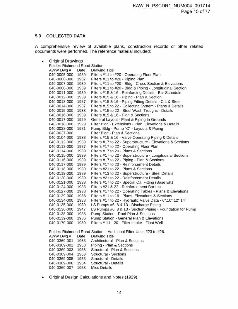
5.3 COLLECTED DATA
A comprehensive review of available plans, construction records or other related documents were performed. The reference material included:
• Original Drawings Folder: Richmond Road Station AWW Dwg # Date Drawing Title 040-0005-000 1939 Filters #11 to #20 - Operating Floor Plan 040-0006-000 1937 Filters #11 to #20 - Piping Plan 040-0007-000 1939 Filters #11 to #20 - Bldg - Cross Section & Elevations 040-0008-000 1939 Filters #11 to #20 - Bldg & Piping - Longitudinal Section 040-0011-000 1939 Filters #15 & 16 - Reinforcing Details - Bar Schedule 040-0012-000 1939 Filters #15 & 16 - Piping - Plan & Section 040-0013-000 1937 Filters #15 & 16 - Piping Fitting Details - C.I. & Steel 040-0014-000 1937 Filters #15 to 22 - Collecting System - Plans & Details 040-0015-000 1938 Filters #15 to 22 - Steel Wash Troughs - Details 040-0016-000 1939 Filters #15 & 16 - Plan & Sections 040-0017-000 1929 General Layout - Plant & Piping In Grounds 040-0018-000 1929 Filter Bldg - Extensions - Plan, Elevations & Details 040-0033-000 1931 Pump Bldg - Pump "C" - Layouts & Piping 040-0037-000 Filter Bldg - Plan & Sections 040-0104-000 1938 Filters #15 & 16 - Valve Operating Piping & Details 040-0112-000 1939 Filters #17 to 22 - Superstructure - Elevations & Sections 040-0113-000 1937 Filters #17 to 22 - Operating Floor Plan 040-0114-000 1939 Filters #17 to 20 - Plans & Sections 040-0115-000 1939 Filters #17 to 22 - Superstructure - Longitudinal Sections 040-0116-000 1939 Filters #17 to 22 - Piping - Plan & Sections 040-0117-000 1939 Filters #17 to 20 - Reinforcement Details 040-0118-000 1939 Filters #21 to 22 - Plans & Sections 040-0119-000 1939 Filters #13 to 22 - Superstructure - Steel Details 040-0120-000 1939 Filters #21 to 22 - Reinforcement Details 040-0121-000 1938 Filters #17 to 22 - Special C.I. Fitting (Base Ell.) 040-0124-000 1938 Filters #21 & 22 - Reinforcement Bar List 040-0127-000 1938 Filters #17 to 22 - Operating Tables - Plans & Elevations 040-0129-000 1938 Filters #11 to 16 - Plans, Elevations & Sections 040-0134-000 1938 Filters #17 to 22 - Hydraulic Valve Data - 6",10",12",14" 040-0135-000 1939 LS Pumps #6, 8 & 13 - Discharge Piping 040-0136-000 1947 LS Pumps #6, 8 & 13 - Suction Piping - Foundation for Pump 040-0138-000 1938 Pump Station - Roof Plan & Sections 040-0139-000 1936 Pump Station - General Plan & Elevations 040-0170-000 1939 Filters # 11 - 20 - Filter Intake - Float Well Folder: Richmond Road Station – Additional Filter Units #23 to #26. AWW Dwg # Date Drawing Title 040-0369-001 1953 Architectural - Plan & Sections 040-0369-002 1953 Piping - Plan & Sections 040-0369-003 1953 Structural - Plan & Sections 040-0369-004 1953 Structural - Sections 040-0369-005 1953 Structural - Details 040-0369-006 1954 Structural - Details 040-0369-007 1953 Misc Details
• Original Design Calculations and Notes (1929).
14
KAW_R_PSCDR1_NUM004_091714 Page 15 of 77

6 DISCUSSION OF SITE VISIT
6.1 OBSERVED CONDITIONS
Inspections of the structure were conducted by American Water Corporate Engineering and Kentucky American Water on August 23 and 24, 2012 requiring two day inspection.
A complete photo record is presented in a separate PDF file. However, a summary of the major problems found during the inspection has been described in the pictures below:
Photo 6.1. Large spalling of concrete and rusting of reinforcement on the roof beams in the 1929 filters
Photo 6.2. Large spalling of concrete and rusting of reinforcement on the operating floor in the 1929 filters
15
KAW_R_PSCDR1_NUM004_091714 Page 16 of 77

Photo 6.3. Efflorescence staining at the walls on filter 12
Photo 6.4. Leakage, liquid on filter walls
16
KAW_R_PSCDR1_NUM004_091714 Page 17 of 77

Photo 6.5. Disintegration and corrosion of bolts on flanged pipe
Photo 6.6. Serious concerns on the condition of the steel pipe hangers at the 36” diam influent Pipe (1938).
17
KAW_R_PSCDR1_NUM004_091714 Page 18 of 77

Photo 6.7. Concerns on the condition of the 30” diam pipe
Photo 6.8. Steel deterioration at pipe supports
18
KAW_R_PSCDR1_NUM004_091714 Page 19 of 77

Photo 6.9. Craze cracking at top slab at Filter No. 16 (1936)
Photo 6.10. Severe damage on concrete top slab. Cracks of varying widths, deformation and spalling due to corrosion of reinforcement. Filters No. 20 (1938).
19
KAW_R_PSCDR1_NUM004_091714 Page 20 of 77

Photo 6.11. Severe delamination at exterior filter wall – East Side-Filter No. 22 (1938)
Photo 6.12. Severe damage on concrete top slab. Filter No. 22 (1953)
20
KAW_R_PSCDR1_NUM004_091714 Page 21 of 77

Photo 6.13. Severe damage on concrete filter walls. Deformation and spalling due to corrosion of reinforcement Filter No. 20 (1936
Photo 6.14. Joint spall and sealant failure between filters No. 21 (1938) and 23 (1953).
21
KAW_R_PSCDR1_NUM004_091714 Page 22 of 77

Photo 6.15. Condition of the top slab. Filters 24 to 26 (1953)
Photo 6.16. Moisture on the veneer at Southern walls
22
KAW_R_PSCDR1_NUM004_091714 Page 23 of 77

Photo 6.17. General view o the condition of the filter wall at Northern side. Filters No. 20 to 26 (1938 -1953)
Photo 6.18. Disintegration due to erosion and abrasion at the floor slab -entrance of filter building
23
KAW_R_PSCDR1_NUM004_091714 Page 24 of 77
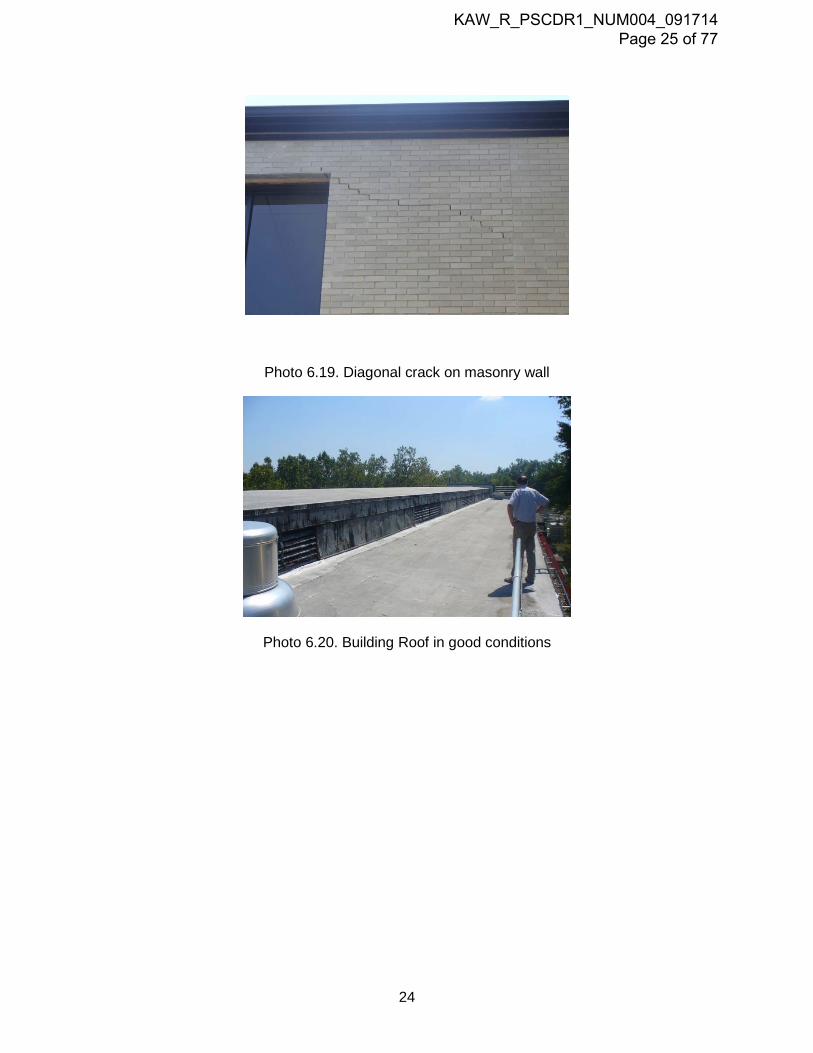
Photo 6.19. Diagonal crack on masonry wall
Photo 6.20. Building Roof in good conditions
24
KAW_R_PSCDR1_NUM004_091714 Page 25 of 77
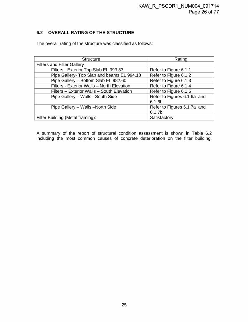
6.2 OVERALL RATING OF THE STRUCTURE
The overall rating of the structure was classified as follows:
Structure Rating Filters and Filter Gallery
Filters - Exterior Top Slab EL 993.33 Refer to Figure 6.1.1 Pipe Gallery- Top Slab and beams EL 994.18 Refer to Figure 6.1.2 Pipe Gallery – Bottom Slab EL 982.60 Refer to Figure 6.1.3 Filters - Exterior Walls – North Elevation Refer to Figure 6.1.4 Filters – Exterior Walls – South Elevation Refer to Figure 6.1.5 Pipe Gallery – Walls –South Side Refer to Figures 6.1.6a and
6.1.6b Pipe Gallery – Walls –North Side Refer to Figures 6.1.7a and
6.1.7b Filter Building (Metal framing) : Satisfactory A summary of the report of structural condition assessment is shown in Table 6.2 including the most common causes of concrete deterioration on the filter building.
25
KAW_R_PSCDR1_NUM004_091714 Page 26 of 77

7 OFFICE ANALYSIS 7.1 TESTING RESULTS
7.1.1 Rebound Hammer Non destructive testing were performed on the concrete including rebound hammer testing to estimate compressive strength of the concrete, the measurements have been summarized in Table 7.1.1. Measurements were taken in areas were the concrete surface was smooth, dry and free of any decay or scalling. In general, compressive strength of the concrete are higher than 4,500 psi.
Table 7.1.1 Rebound H
36
KAW_R_PSCDR1_NUM004_091714 Page 27 of 77

ammer Readings.
Photo 7.1.1 Estimating concrete compressive strength using the Rebound hammer
7.1.2 Crack measurements
Measurements of crack length were also performed at the interior walls within the pipe gallery. The measurements have been summarized in Table 7.1.2 and their location is shown in Figures 6.16.a, 6.1.6b, 6.1.7a and 6.1.7b.
Table 7.1.2 Crack Measurements.
Cracks on the exterior walls were not measured, however the condition of the northern wall was visually inspected and their condition is shown in Figure 6.1.4. The walls at the southern side of the filter building were not inspected since they have a brick veneer installed over the concrete structure, however moisture on several spots are evidence of possible leakage through the walls.
7.1.3 Readings on steel pipe hangers.
Condition of the steel pipe hanger for the 36” and 30” water main was evaluated at several l location using a micrometer. The measurements have been summarized in Table 7.1.3
37
KAW_R_PSCDR1_NUM004_091714 Page 28 of 77

Table 7.1.3 Readings on steel pipe hangers.
Photo 7.1.3. Measurements in steel using the Micrometer
JOB SHEET NO 1 OF 1 CALCULATED BY J.J DATE 11/1/2012 CHECKED BY DATE
PIPE HANGERS - DIAMETER READINGS
ID Location Actual Diam Original Estim Section 1 2 (in) Diam (in) loss
A Filters 21-22 27.5 23.8 0.94 1 7% B Filters 19-20 24.5 24.5 0.96 1 4% C Filters 19-20 23.4 0.92 1 9% D Filters 17-18 24.5 0.96 1 4% E Filters 17-18 23.7 0.93 1 7%
Filter building
Readings (mm)
38
KAW_R_PSCDR1_NUM004_091714 Page 29 of 77
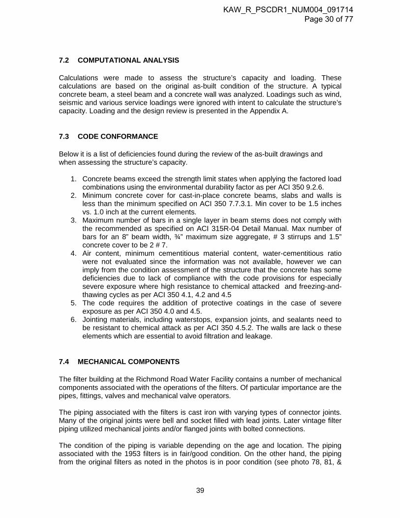
7.2 COMPUTATIONAL ANALYSIS
Calculations were made to assess the structure’s capacity and loading. These calculations are based on the original as-built condition of the structure. A typical concrete beam, a steel beam and a concrete wall was analyzed. Loadings such as wind, seismic and various service loadings were ignored with intent to calculate the structure’s capacity. Loading and the design review is presented in the Appendix A.
7.3 CODE CONFORMANCE
Below it is a list of deficiencies found during the review of the as-built drawings and when assessing the structure’s capacity.
1. Concrete beams exceed the strength limit states when applying the factored load combinations using the environmental durability factor as per ACI 350 9.2.6.
2. Minimum concrete cover for cast-in-place concrete beams, slabs and walls is less than the minimum specified on ACI 350 7.7.3.1. Min cover to be 1.5 inches vs. 1.0 inch at the current elements.
3. Maximum number of bars in a single layer in beam stems does not comply with the recommended as specified on ACI 315R-04 Detail Manual. Max number of bars for an 8” beam width, ¾” maximum size aggregate, # 3 stirrups and 1.5” concrete cover to be 2 # 7.
4. Air content, minimum cementitious material content, water-cementitious ratio were not evaluated since the information was not available, however we can imply from the condition assessment of the structure that the concrete has some deficiencies due to lack of compliance with the code provisions for especially severe exposure where high resistance to chemical attacked and freezing-and-thawing cycles as per ACI 350 4.1, 4.2 and 4.5
5. The code requires the addition of protective coatings in the case of severe exposure as per ACI 350 4.0 and 4.5.
6. Jointing materials, including waterstops, expansion joints, and sealants need to be resistant to chemical attack as per ACI 350 4.5.2. The walls are lack o these elements which are essential to avoid filtration and leakage.
7.4 MECHANICAL COMPONENTS
The filter building at the Richmond Road Water Facility contains a number of mechanical components associated with the operations of the filters. Of particular importance are the pipes, fittings, valves and mechanical valve operators. The piping associated with the filters is cast iron with varying types of connector joints. Many of the original joints were bell and socket filled with lead joints. Later vintage filter piping utilized mechanical joints and/or flanged joints with bolted connections. The condition of the piping is variable depending on the age and location. The piping associated with the 1953 filters is in fair/good condition. On the other hand, the piping from the original filters as noted in the photos is in poor condition (see photo 78, 81, &
39
KAW_R_PSCDR1_NUM004_091714 Page 30 of 77

294). None of the piping is in danger of imminent failure. However, there are serious signs of corrosion and tuberculation along the pipe. Some of the flanges and mechanical joints are noted as deteriorated and in need of repair (see photo 81). Further examination is required to determine the extent of corrosion and type of repair. Of particular concern are the connections associated with the piping. Pipe supports are corroded and tuberculated (pitted) and show signs of severe corrosion (see photo 49) . Serious consideration should be given to immediate replacement of the most corroded supports. In addition, the connector bolts in many of the mechanical joints and flanges are severely deteriorated. The photos show bolts that are completely corroded (see photos 75 & 114) The electrically operated valves associated with the filters are butterfly type and were part of the original construction. Filters and valves were added in 1936, 1937 and 1953 and were of similar construction. Other types of valves are found throughout the piping used largely as isolation valves and appear to be manually operated. Valve extensions rise from the piping gallery through the floor to the operating room above allowing for manual isolation. The valve operators for the filters were originally comprised of Pratt and BIF operators. Old BIF actuators were replaced over the last several years with EIM actuators. The entire first effluent valve operators have now been replaced with EIM actuators. In addition, the filter wash flow control valves were BIF. However, the actuators were replaced with EIM modulating operators for backwash and flow control. According to the operations staff, all of the valves and actuators associated with the filter are operational. However, it has been noted that they are in need of constant repair due to their age and the corrosive environment that exists in the piping galley. Some of the operators are relatively new having been replaced within the last five (5) years and can be considered in fair/good condition. However, the remaining operators should be considered poor/fair in condition and will need replacement over time (within next 5 – 10 years). The overall condition of the valves is hard to assess since internal inspections were not possible. A reasonable assumption is that the valves will need replacement over the next 5-10 years at increasing frequency due to their age and the corrosive environment they are present in. The operations staff indicates that removal of the valves is possible through existing access hatches and front and back egresses. However, it is possible, that in some locations, the only possible means for removal may be through a hole in the operations floor. The associated pictures note the confined conditions and limited enter and exit points (see photo 78 & 289).
40
KAW_R_PSCDR1_NUM004_091714 Page 31 of 77

8 CONCLUSIONS AND RECOMMENDATIONS The Filter building at Richmond Road Station is an old structure with significant deterioration due to the adverse environment it has been exposed. The rating of the structure varies along its structural components and the dates of construction but in general the filter gallery and the exterior walls between filters 11 to 22 (1924 to 1938 construction) can be classified as in poor to severe condition and extensive repairs need to be done to rehabilitate this part of the structure. The condition of the filters 23 to 26 (1953 construction), the bottom slab of the pipe gallery and the steel frame structure above the operating floor can be classified as satisfactory.
8.1 FILTER GALLERY
8.1.1 Floor slab The most critical deterioration is presented in the operating floor slab above the headwork area (1924 construction). 80% of the slab in this section has exposed rebars that need to be recoated. The slab is also in poor condition at selected places between filters 11 to 20. (1924 to 1937 construction) and satisfactory between filters 21 to 26 (1938 and 1953 construction). Although the existing reinforcing is adequate to resist the actual loads and no additional reinforcing is needed, the exposed rebars must be clean, protect with a corrosion inhibitor and their concrete cover be reestablished with a repair mortar. After reestablishing the concrete cover on the concrete slab, a corrosion-resistant protective coating is highly recommended to be applied.
8.1.2 Concrete beams The most critical deterioration is presented in the operating floor slab between Filters 11 to 20. Possible causes vary from moist exposure and corrosive environment to lack of adequate concrete cover. 58% of the concrete beams in this section of the slab have experienced lost of concrete cover and also have exposed and corroded reinforcement. Beam repairs must be done to stop deterioration due to corrosion of reinforcement and to avoid further deterioration that can compromise the structural capacity of the concrete beams. Special attention must be done where the beams carry the 36” Cast Iron pipe.. It is important to notice that the beams are not code compliance since the concrete beams exceed the strength limit states when applying the factor load combination using the environmental durability factor as per ACI 350 section 9.2.6. A proposed methodology to strengthen the concrete beams is presented in Figure 8.1.2. After finishing a complete structural strengthened system on the concrete beams, a corrosion-resistant protective coating is highly recommended.
41
KAW_R_PSCDR1_NUM004_091714 Page 32 of 77

Figure 8.1.2 Structural Strengthened System for deteriorated concrete beams.
8.1.3 Concrete walls Non-structural concrete cracks are extensive in the walls at the pipe gallery. All concrete cracks need to be sealed to stop leaks and to minimize future deterioration of both the concrete and reinforcement. Cracks can be bonded by the injection of epoxy. The technique generally consists of:
• Cleaning the cracks • Sealing the surfaces • Installing the entry and venting ports at close intervals along the cracks • Mixing the epoxy • Injecting the epoxy under pressure • Removing the surface seal.
Wet cracks can be injected using moisture-tolerant materials that will cure and bond in the presence of moisture, but contaminants in the cracks can reduce the effectiveness of
42
KAW_R_PSCDR1_NUM004_091714 Page 33 of 77

the epoxy to structurally repair the cracks. An application procedure and recommended product is presented in Appendix B. After finishing a complete crack repair program on the concrete walls, a corrosion-resistant protective coating is highly recommended.
8.1.4 Bottom Slab The condition of the bottom slab of the filter gallery is satisfactory and no additional repairs need to be done. However a corrosion-resistant protective coating is highly recommended.
8.1.5 Steel Hanger Supports for the 36” Cast Iron Pipe All steel hangers supports for the 36” CI pipe need to be replaced by stainless steel or galvanized steel hanger supports unless a detailed assessment of the condition of the supports indicates that the steel is adequate to withstand the loads.
8.1.6 Steel Pipe Supports Corroded pipe supports need to be repaired. A detailed take off of these elements need to be performed.
8.1.7 Steel ladder All steel ladders need to be replaced and follow the requirements established by OSHA.
43
KAW_R_PSCDR1_NUM004_091714 Page 34 of 77

8.2 FILTER TANKS
8.2.1 Top slab The evaluation of the condition of the top slab for filters 12 and 13 was not possible since the top slab was completely buried during the inspection. The condition of the floor slabs for filters 15, 16, 17, 22 and 23 can be classified as in poor/severe condition; it represents 34% of the total roof area. The condition of the top slab for filters 19 and 20 is critical; it represents 12% of the total roof area. Concrete readings using the rebound hammer at the locations mentioned before were not possible due to the extensive deterioration and scalling of the concrete surface, however the structure sounded hollow at several locations specially along the section supported between the exterior concrete wall and the 12”W x 16”H concrete beam which represents a major concern from a structural standpoint. Two approaches may be considered for the repair of the top slab:
1. Strengthening the slab by increasing its depth from top as illustrated in Figure 8.2.1 However additional testing needs to be done on the structure to better evaluate the condition of the concrete and steel reinforcing.
Figure 8.2.1 Structural Strengthened System for deteriorated concrete beams.
44
KAW_R_PSCDR1_NUM004_091714 Page 35 of 77

2. Demolishing the existing concrete beams and concrete slab and installing a new roof system using hollowcore concrete planks supported on the existing concrete walls.
Finally, the condition of the top slab for the remaining filters (11,13,18,21,24,25 and 26) is satisfactory, it represents 43% of the total roof area.
8.2.2 Concrete walls The walls at the southern side of the filter building were not inspected since they have a brick veneer installed over the concrete structure, however moisture on several spots are evidence of possible leakage through the walls. Removing the existing concrete veneer and additional testing are required in order to better assess the condition of the wall.
The walls at the northern side for filters 12 and 14 were not inspected since they were buried during the inspection. Excavating and additional testing along the northern wall are required in order to better assess the condition of the wall. The most critical walls at the northern side of the filter building correspond to filters 20 and 22. Cracking, staining and leaking are indicative of serious distress problems on the structure. The lack of concrete resistant to freezing and thawing and chemical attack has developed cracks and deterioration. The walls need to be replaced entirely or strengthened as illustrated in the Figure 8.2.2 and damproofing.
Figure 8.2.2 Structural Strengthened System for deteriorated concrete walls.
45
KAW_R_PSCDR1_NUM004_091714 Page 36 of 77

Non-structural concrete cracks on the exterior walls need to be sealed as explained on section 8.1.3.
8.3 STEEL FRAME BUILDING
The overall condition of the steel frame structure above the operating floor can be classified as satisfactory.
8.4 MECHANICAL COMPONENTS INCLUIDING PIPING, VALVES AND OPERATORS
The overall condition of the mechanical components of the filter gallery is poor/fair. The valve operators have been largely changed out over the years but are still in need of constant repair. This is particularly true of the older style many of which remain. Access to the valve gallery is poor and the ability to service the equipment is difficult at best. The valves that service the filters are very old dating back to the original construction in the 1930’s. Their replacement will be required over time. Due to the severe space constraints associated with the gallery, their replacement will be very difficult and, in some cases, may require excavation of the operating floor slab for access. In addition, due to moisture and chlorine gas accumulation in the gallery, severe corrosion of the piping has occurred in several locations. Of particular concern are the pipe joints which have corroded bolts and associated hardware. Many of these joints need to be completely replaced.
Due to the corrosive environment in the Filter Gallery, it is recommended that the electrically operated valves and actuators be replaced with new valves and pneumatically operated actuators. This will enhance the operational life of the operators by eliminating the electrical components subject to corrosion. This only pertains to the non-modulating valves. The modulating valves used for backwash of the filters must remain as electrically operated mechanical valves.
Replacement of existing valves, operators and associated components will prolong the useful life of the Filter Building. However, the longevity of any repairs needs to be weighed against the costs and overall functionality of the structure. A review of the structural deficiencies of the filter building raises serious concerns as to the efficacy of replacing piping, valves, operators and associated components with a life expectancy of less than 20-25 years. In addition, any repair may reveal deficiencies undiscovered to date further questioning the cost effectiveness of repair versus replacement. In conclusion, serious consideration should be given to replacement of the existing filters.
8.5 SHORT TERM REMEDIATION
Based on the conditions observed to date, the following actions are recommended to be implemented immediately:
1. Repair and reinforce 10 concrete beams rated critical, 6 concrete beams rated serious and 8 concrete beams rated poor as indicated in Figure 6.1.2 by strengthening their structural system as illustrated in Figure 8.1.2.
46
KAW_R_PSCDR1_NUM004_091714 Page 37 of 77

2. Recoat the concrete roof slab at selected places as indicated in Figure 6.1.2 by removing the existing concrete cover, applying a corrosion inhibitor, reestablishing the concrete cover with a repair mortar and applying a corrosion-resistant protective coating.
3. Replace all steel hanger support for the 36” Cast Iron pipe by installing new stainless steel/galvanized steel hanger pipe supports.
4. Ensure people are following safe practices by posting clear authorized personnel signs and restricted area on the concrete roof slab between filters 15 to 23.
47
KAW_R_PSCDR1_NUM004_091714 Page 38 of 77

JOB
SHEET NO 1 OF 1CALCULATED BY J.J DATE 10/25/12CHECKED BY DATE
PRELIMINARY ESTIMATE - STRUCTURAL WORKDESCRIPTION GRADE OF QTY UNIT UNIT COST NOTES
DIFFICULTY COST
A General Conditions 5.0 % of total 100,000$ B Mobilization 5.0 day 5,000$ 25,000$ C Clearing 1.0 L.S 10,000$ 10,000$ D Pipe Gallery Repairs
1. Roof beam Demolition 2 90 CF 90$ 16,200$ 2. Installation of new steel beams
2.1 Steel beams 2 211 LF 59$ 24,900$ 2.2 Concrete cover 2 56 CY 700$ 78,400$
3. Structural Strenghtening System3.1 Scalfolding for beams 3 106 EA 24$ 7,700$ 3.2 Removing the concrete cover 3 9 CY 500$ 13,500$ 3.3 Blast cleaning of exposed rebars 3 1,440 SF 10$ 43,200$ 3.4 Application of prime bonding agent Sika Armatec 110 Epocem 3 1,440 SF 18$ 78,800$ 3.5 Installing vertical and horizontal dowels -$
3.5.1 Vertical and horizontal dowels 3 9 Ton 3,130$ 84,600$ 3.5.2 Installing dowel with Sika Anchor Fix -4 3 2 CF 4,461$ 26,800$
3.6 Installing steel reinforcement 3 1 Ton 3,130$ 9,400$ 3.7 Application of cementitious repair mortar Sikatop123 Plus 3 9 CY 900$ 23,700$
4. Replacement of Hanger Pipe Supports 30" CI Pipe 3 20 EA 1,000$ 60,000$ 5. Replacement of Standup Pipe Supports 2 20 EA 1,000$ 40,000$ 6. Replacement of Steel Ladders 2 6 EA 1,000$ 12,000$ 7. Crack Repair System
7.1 Blast cleaning 2 7,035 SF 10$ 140,700$ 7.2 Sealing leaking cracks or joints with HydroActive 2 280 LF 100$ 56,000$ 7.3 Installation of extrudable swelling waterstop Sikaswell S-2 3 185 LF 50$ 27,800$ 7.4 Installation of corrosion-resistant protective coating Sikagard 62 2 9,560 SF 14$ 267,700$
STRUCTURAL COMPONENT
E Filters - Exterior1. Excavation 1 350 CY 10$ 3,500$ 2. Backfill 1 350 CY 10$ 3,500$ 3. Top Slab Demolition 2 424 CF 48$ 40,800$ 4. Roof beam Demolition 2 95 CF 90$ 17,100$ 5. Demolition of concrete walls 2 243 CF 38$ 18,500$ 6. New concrete walls 2 9 CF 700$ 12,600$ 7. Waterstop joints 2 72 FT 100$ 14,400$ 8. Hollowcore planks
8.1 Installing Hollowcore Planks 1 1,271 SF 10$ 13,200$ 8.2 Concrete topping 1 12 CY 500$ 6,000$
9. Demolition of brick veneer - Southern Filters 2 1,790 SF 5$ 17,900$ 10. Installation of brick Veneer 2 1,790 SF 15$ 53,700$ 11. Core samples and petrographic analysis 1 32 EA 1,000$ 32,000$ 12. Crack Repair System
12.1 Blast cleaning 1 3,790 SF 10$ 37,900$ 12.2 Sealing leaking cracks or joints with HydroActive 1 550 LF 100$ 55,000$
13. Damproofing northern exterior walls 1 3,790 SF 10$ 37,900$ 14. Crack repair in Masonry walls 1 1.0 LS 10,000$ 10,000$
F Demobilization 5.0 day 5,000$ 25,000$ G Restoration 1.0 Allowance 10,000$ 10,000$ H Contingency 30.0 % of total 667,000$
Total 2,223,000$
1. Top Slab demolition/ 2 Roof Beam Demolition1 For congested sites or small quantities, add up to 200% 02 41 13.33 44002 For disposal to 5 miles add 15.20 02 41 13.33 45003 Concrete elevated slab, bar reinforced, over 6CF
KAW_R_PSCDR1_NUM004_091714 Page 39 of 77

JOB
SHEET NO 1 OF 1CALCULATED BY A.H DATE 12/03/12CHECKED BY DATE
Cost Estimate - Mechanical Components - Richmond Road FiltersItem Description Qty Unit Price Total
Materials1 Misc. Pipe Replacement 250 LF 100$ 25,000$ 2 Joint replacment 24 Ea 1,000$ 24,000$ 3 Megalug Retainer w/ Kit 20 Ea 350$ 7,000$ 4 Pneumatic Actuators 36 Ea 20,000$ 720,000$ 5 Electrical Actuators 12 Ea 20,000$ 240,000$ 6 Valves 48 Ea 15,000$ 720,000$ 7 Misc. Materials including bolts, gaskets etc. 1 LS 10,000$ 10,000$ 8 Contractor Mark-up of Materials 1 LS 349,200$
Subtotal 2,095,200$
LaborConstruction Labor Crew cost 120 days 5,000$ 600,000$ Coordination, mobilization/demobilization, material delivery 25 days 5,000$ 125,000$ Subtotal 725,000$
EquipmentCrane/ hoist/ Trucks etc 1 LS 250,000$ 250,000$ Subtotal 250,000$
Total 3,070,200$Contractor OH& Profit (20%) 614,040$
Engineering Design and construction Mgt (12 %) 442,109$
30% Contingency 1,105,272$
T t l P j t 5 231 621$
COST ESTIMATES - MECHANICAL COMPONENTS
Total Project 5,231,621$
KAW_R_PSCDR1_NUM004_091714 Page 40 of 77

FIGURES
KAW_R_PSCDR1_NUM004_091714 Page 41 of 77

KAW_R_PSCDR1_NUM004_091714 Page 42 of 77
jimeneje
Typewritten Text
Figure 6.1.1

KAW_R_PSCDR1_NUM004_091714 Page 43 of 77
jimeneje
Typewritten Text
Figure 6.1.2

KAW_R_PSCDR1_NUM004_091714 Page 44 of 77
jimeneje
Typewritten Text
Figure 6.1.3

KAW_R_PSCDR1_NUM004_091714 Page 45 of 77
jimeneje
Typewritten Text
Figure 6.1.4

KAW_R_PSCDR1_NUM004_091714 Page 46 of 77
jimeneje
Typewritten Text
Figure 6.1.5

KAW_R_PSCDR1_NUM004_091714 Page 47 of 77
jimeneje
Typewritten Text
Figure 6.1.6a

KAW_R_PSCDR1_NUM004_091714 Page 48 of 77
jimeneje
Typewritten Text
jimeneje
Typewritten Text
Figure 6.1.6b

KAW_R_PSCDR1_NUM004_091714 Page 49 of 77
jimeneje
Typewritten Text
Figure 6.1.7a

KAW_R_PSCDR1_NUM004_091714 Page 50 of 77
jimeneje
Typewritten Text
Figure 6.1.7b

TABLE 6.2
KAW_R_PSCDR1_NUM004_091714 Page 51 of 77

JOB
SHEE
T N
O1
OF
3
CA
LCU
LATE
D B
YJ.
JD
ATE
11/0
1/12
CH
ECK
ED B
YD
ATE
TAB
LE 6
.2 C
ON
DIT
ION
ASS
ESSM
ENT
OF
THE
FILT
ER T
AN
KS
Stru
ctur
eW
idth
Leng
thA
rea
(ft)
(ft)
(SF)
Bot
tom
sla
b13
.518
.525
0To
p S
lab
13.5
18.5
250
Wal
ls18
.511
.92
221
Bea
m (B
otto
m s
urfa
ce)
0.67
13.5
9
Loca
tion
Ele
men
tC
ondi
tion
Cra
ckin
gS
tain
ing
Leak
ing
Sca
ling
Spa
lls a
ndE
fflor
esce
nce
Lost
of
Are
a %
Ext
ent
Bug
hole
sH
oney
com
bS
tain
ing
Cra
zeD
-cra
cks
Hai
rline
Map
Dia
gona
lLo
ngitu
dina
lTr
ansv
.R
ando
mpo
pout
sLo
ng.
Tran
sv.
cove
r(S
F)Fi
lter 1
1-12
Bot
tom
sla
bG
ood
Top
slab
Poo
rx
xx
156%
B-1
Poo
r/sev
ere
xx
xx
20%
B-2
Fair
B-3
Fair
B-4
Fair
B-5
Poo
rx
x10
%B
-6Fa
i rW
all F
ilter
11
Fair
xx
xx
Wal
l Filt
er 1
2P
oor
xx
xx
x
Filte
r 13-
14B
otto
m s
lab
Goo
dTo
p sl
abP
oor
xx
4418
%B
-1P
oor/s
ever
ex
xx
B-2
Fair
B-3
Fair
B-4
Fair
Filte
r Bui
ldin
g
Dam
age
Dis
tress
indi
cato
rsS
urfa
ce c
ondi
tion
of c
oncr
ete
Fini
sh s
urfa
ceC
rack
ing
Reb
ars
expo
sed
B-4
Fair
B-5
Poo
rx
xx
B-6
Crit
ical
xx
x80
%W
all F
ilter
13
Poo
rx
xx
Wal
l Filt
er 1
4Fa
irx
xx
xx
xx
Filte
r 15-
16B
otto
m s
lab
Fair
xx
Top
slab
Poo
rx
x20
%B
-1P
oor
xx
10%
B-2
Fai r
B-3
Fair
B-4
Fair
B-5
Fair
B-6
Crit
ical
xx
xx
50%
Wal
l Filt
er 1
5P
oor
xx
xx
xx
xx
xW
all F
ilter
16
Poo
rx
xx
xx
Filte
r 17-
18B
otto
m s
lab
Fair
xTo
p sl
abFa
irB
-1C
ritic
alx
xx
xB
-2Fa
irB
-3P
oor
xx
xB
-4Fa
irB
-5Fa
irB
-6C
ritic
alx
xx
xW
all F
ilter
17
Poo
rx
xx
xx
xx
Wal
l Filt
er 1
8P
oor
xx
xx
Filte
r 19-
20B
otto
m s
lab
Fair
Top
slab
Poo
rx
x20
%B
-1C
ritic
alx
xx
x40
%B
-2P
oor
B-3
Poo
rB
-4Fa
irB
-5C
ritic
alx
xx
xx
x40
%B
-6S
ever
ex
xx
Wal
l Filt
er 1
9P
oor
xx
xx
Wal
l Filt
er 2
0P
oor
xx
xx
x
KAW_R_PSCDR1_NUM004_091714 Page 52 of 77

JOB
SHEE
T N
O2
OF
3
CA
LCU
LATE
D B
YJ.
JD
ATE
11/0
1/12
CH
ECK
ED B
YD
ATE
Filte
r 21-
22B
otto
m s
lab
Fair
xTo
p sl
abFa
irB
-1C
ritic
alx
xx
x40
%B
-2Fa
irB
-3Fa
irB
-4Fa
irB
-5Fa
irB
-6P
oor
x10
%W
all F
ilter
21
Poo
rx
xx
x10
%W
all F
ilter
22
Fair
xx
Filte
r 23-
24B
otto
m s
lab
Fair
Top
slab
Fair
B-1
Sev
ere
xx
30%
B-2
Fair
B-3
Fair
B-4
Fair
B-5
Fair
Wal
l Filt
er 2
3Fa
irx
xW
all F
ilter
24
Fair
Filte
r 25-
26B
otto
m s
lab
Fair
Top
slab
Fair
B-1
Fair
B-2
Sev
ere
xx
xx
25%
B-3
Fair
B-4
Fair
Filte
r Bui
ldin
g
B-4
Fair
B-5
Fair
Wal
l Filt
er 2
5Fa
irW
all F
ilter
26
Fair
KAW_R_PSCDR1_NUM004_091714 Page 53 of 77

JOB
SHEE
T N
O3
OF
3
CA
LCU
LATE
D B
YJ.
JD
ATE
11/0
1/12
CH
ECK
ED B
YD
ATE
TAB
LE 6
.2 C
ON
DIT
ION
ASS
ESSM
ENT
OF
THE
FILT
ER T
AN
KS
Loca
tion
Ele
men
tC
ondi
tion
Cra
ckin
gS
tain
ing
Leak
ing
Sca
ling
Spa
lls a
ndE
fflor
esce
nce
Lost
of
Are
a %
Ext
ent
Bug
hole
sH
oney
com
bS
tain
ing
Cra
zeD
-cra
cks
Hai
rline
Map
Dia
gona
lLo
ngitu
dina
lTr
ansv
.R
ando
mpo
pout
sLo
ng.
Tran
sv.
cove
r(S
F)Fi
lter 1
1To
p sl
abFa
irx
Wal
lB
rick
Ven
eer
Filte
r 12
Top
slab
Not
insp
ecte
dW
all
Not
insp
ecte
d
Filte
r 13
Top
slab
Fair
Wal
lB
rick
Ven
eer
Filte
r 14
Top
slab
Not
insp
ecte
dW
all
Not
insp
ecte
d
Filte
r 15
Top
slab
Poo
rx
xx
x40
%W
all
Bric
k V
enee
r
Filte
r 16
Top
slab
Poo
rx
xx
Wal
lFa
irx
x
Filte
r 17
Top
slab
Poo
rx
xx
xx
Wal
lB
rick
Ven
eer
Filte
r 18
Top
slab
Fair
xW
all
Fair
Filt
19T
lb
Si
Filte
r Bui
ldin
g
Dis
tress
indi
cato
rsS
urfa
ce c
ondi
tion
of c
oncr
ete
Dam
age
Fini
sh s
urfa
ceC
rack
ing
Reb
ars
expo
sed
Filte
r 19
Top
slab
Ser
ious
xx
xx
xx
xx
Wal
lB
rick
Ven
eer
Filte
r 20
Top
slab
Crit
ical
xx
xx
xx
xW
all
Poo
rx
xx
x
Filte
r 21
Top
slab
Poo
r/Fai
rx
xW
all
Bric
k V
enee
r
Filte
r 22
Top
slab
Poo
rx
xW
all
Crit
ical
xx
xx
xx
xx
x
Filte
r 23
Top
slab
Poo
rx
xW
all
Bric
k V
enee
r
Filte
r 24
Top
slab
Fair
Wal
lFa
irx
Filte
r 25
Top
slab
Fair
xW
all
Bric
k V
enee
r
Filte
r 26
Top
slab
Goo
dW
all
Fair
x
KAW_R_PSCDR1_NUM004_091714 Page 54 of 77

APPENDIX A
KAW_R_PSCDR1_NUM004_091714 Page 55 of 77

KENTUCKY AMERICAN WATER
RICHMOND ROAD - FILTER BUILDING
STRUCTURAL CALCULATIONS
Javier E Jimenez, P.E
Date By
PREPARED BY
Designed 11/01/12 J.JRevised
QC CheckApproved
KAW_R_PSCDR1_NUM004_091714 Page 56 of 77

JOB
SHEET NO 1 OF 15CALCULATED BY J.J DATE 11/01/12CHECKED BY DATE
1.0 OPERATING FLOOR EVALUATION
1.1 Load Evaluation
Dead loads
4" concrete slab 50 psf [Filters 11 to 22]Superimposed dead load 40 psf [Mechanical duct allowance, insulation,etc]
90.0 psf
5" concrete slab 62.5 psf [Filters 23 to 25]Superimposed dead load 40 psf [Mechanical duct allowance, insulation,etc]
102.5 psf
Filters Pipe Material ID OD Pipe Water Total(in) (pcf) (in) (in) (lb/ft) (lb/ft) (lb/ft)
12 to 15 36 Cast Iron 450 36 38.76 506.4 441.1 947.516 to 27 30 Cast Iron 450 30 32.52 386.7 306.3 693.0
12 Cast Iron 450 12 13.6 100.5 49.0 149.5
Filter Building
Live loads 150 psf
1.2 Load Distribution
1.2.1 Existing Structures
ID Filters DL * LL PB(in) H(in) L(ft) Slab Pipe (kip/ft) (kip/ft) (kip)
B-1 Entrance 8 14 12.5 4.92 0.56 0.74B-2 12 to 15 8 14 13.5 4.08 7.64 0.48 0.61 7.2B-3 16 to 23 8 14 13.5 4.08 7.64 0.48 0.61 5.3B-4 24 to 27 W10X33 13.5 6.25 9.33 1.80 0.94 6.5
* Includes selfweighta= 5.45 ft
1.2.2 New Structures (Beams are increased with 2 in of repair mortar)
ID Filters DL * LL PB(in) H(in) L(ft) Slab Pipe (kip/ft) (kip/ft) (kip)
B-1 Entrance 8 16 12.5 4.92 0.58 0.74B-2 12 to 15 8 16 13.5 4.08 7.64 0.50 0.61 7.2B-3 16 to 23 8 16 13.5 4.08 7.64 0.50 0.61 5.3B-4 24 to 27 W10X33 13.5 6.25 9.33 1.80 0.94 6.5
* Includes selfweight
BeamsDimensions Tributary width (ft)
Dimensions Tributary width (ft)Beams
KAW_R_PSCDR1_NUM004_091714 Page 57 of 77
JOB
SHEET NO 2 OF 15CALCULATED BY J.J DATE 11/01/12CHECKED BY DATE
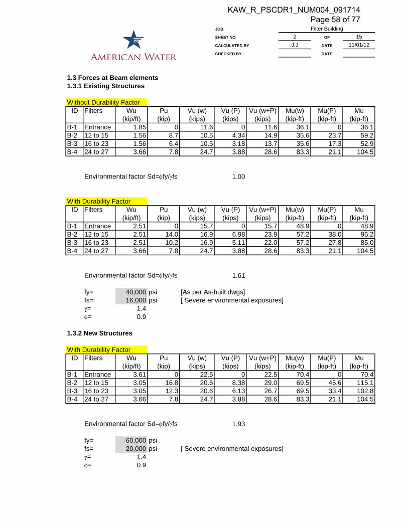
1.3 Forces at Beam elements1.3.1 Existing Structures
Without Durability FactorID Filters Wu Pu Vu (w) Vu (P) Vu (w+P) Mu(w) Mu(P) Mu
(kip/ft) (kip) (kips) (kips) (kips) (kip-ft) (kip-ft) (kip-ft)B-1 Entrance 1.85 0 11.6 0 11.6 36.1 0 36.1B-2 12 to 15 1.56 8.7 10.5 4.34 14.9 35.6 23.7 59.2B-3 16 to 23 1.56 6.4 10.5 3.18 13.7 35.6 17.3 52.9B-4 24 to 27 3.66 7.8 24.7 3.88 28.6 83.3 21.1 104.5
Environmental factor Sd=fy/fs 1.00
With Durability FactorID Filters Wu Pu Vu (w) Vu (P) Vu (w+P) Mu(w) Mu(P) Mu
(kip/ft) (kip) (kips) (kips) (kips) (kip-ft) (kip-ft) (kip-ft)B-1 Entrance 2.51 0 15.7 0 15.7 48.9 0 48.9B-2 12 to 15 2.51 14.0 16.9 6.98 23.9 57.2 38.0 95.2B-3 16 to 23 2.51 10.2 16.9 5.11 22.0 57.2 27.8 85.0
Filter Building
B-4 24 to 27 3.66 7.8 24.7 3.88 28.6 83.3 21.1 104.5
Environmental factor Sd=fy/fs 1.61
fy= 40,000 psi [As per As-built dwgs]fs= 16,000 psi [ Severe environmental exposures]= 1.4= 0.9
1.3.2 New Structures
With Durability FactorID Filters Wu Pu Vu (w) Vu (P) Vu (w+P) Mu(w) Mu(P) Mu
(kip/ft) (kip) (kips) (kips) (kips) (kip-ft) (kip-ft) (kip-ft)B-1 Entrance 3.61 0 22.5 0 22.5 70.4 0 70.4B-2 12 to 15 3.05 16.8 20.6 8.38 29.0 69.5 45.6 115.1B-3 16 to 23 3.05 12.3 20.6 6.13 26.7 69.5 33.4 102.8B-4 24 to 27 3.66 7.8 24.7 3.88 28.6 83.3 21.1 104.5
Environmental factor Sd=fy/fs 1.93
fy= 60,000 psifs= 20,000 psi [ Severe environmental exposures]= 1.4= 0.9
KAW_R_PSCDR1_NUM004_091714 Page 58 of 77

JOB
SHEET NO 3 OF 15CALCULATED BY J.J DATE 11/01/12CHECKED BY DATE
1.4 Checking Slab capacity
f'c= 3,000 psify= 40,000 psi
Bottom 4 @ 8 As= 0.30 in2/ftTop 4 @ 8 As= 0.30 in2/ft
3 @ 18 As= 0.07 in2/ft0.37 in2/ft
Slab Geometry
bw= 12 inSlab thickness,t= 4 inCover= 1.5 inLong side (Lb) 13.5 ftShort span (La) 4.17 ftd pos= 2.5 ind neg= 2.5 inlb/la 3.24 One way slab
Filter Building
Resistant a 1 ca1=a/1 ca1/d Actual MnMoment Mr (in) (in) (kip-ft/ft)Positive 0.39 0.85 0.46 0.18 0.9 0.0100 2.1Negative 0.49 0.85 0.57 0.23 0.9 0.0124 2.5
Dead loads 90 psfLive loads 150 psfSpan= 4.17 ft [critical span]Sd= 1.00wu= Sd(1.2D+1.6L)= 348.0 lb/ft
Mu= Coef *wuL2
Acting Coef Mu CheckMoment M (kip-ft/ft)Positive 0.09 0.55 OkNegative 0.10 0.60 Ok
The reinforcement of the existing 4" concrete slab is adequate toresist the actual loads.
KAW_R_PSCDR1_NUM004_091714 Page 59 of 77
JOB
SHEET NO 4 OF 15CALCULATED BY J.J DATE 11/01/12CHECKED BY DATE
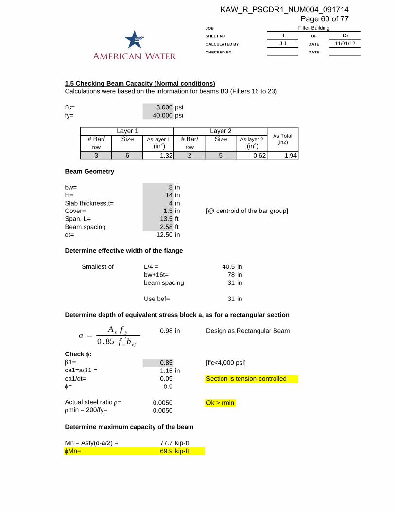
1.5 Checking Beam Capacity (Normal conditions)Calculations were based on the information for beams B3 (Filters 16 to 23)
f'c= 3,000 psify= 40,000 psi
# Bar/ Size As layer 1 # Bar/ Size As layer 2row (in2) row (in2)3 6 1.32 2 5 0.62 1.94
Beam Geometry
bw= 8 inH= 14 inSlab thickness,t= 4 inCover= 1.5 in [@ centroid of the bar group]Span, L= 13.5 ftBeam spacing 2.58 ftdt= 12.50 in
Filter Building
Layer 1 Layer 2As Total
(in2)
Determine effective width of the flange
Smallest of L/4 = 40.5 inbw+16t= 78 inbeam spacing 31 in
Use bef= 31 in
Determine depth of equivalent stress block a, as for a rectangular section
0.98 in Design as Rectangular Beam
Check :1= 0.85 [f'c<4,000 psi]ca1=a/1 = 1.15 inca1/dt= 0.09 Section is tension-controlled= 0.9
Actual steel ratio = 0.0050 Ok > rminmin = 200/fy= 0.0050
Determine maximum capacity of the beam
Mn = Asfy(d-a/2) = 77.7 kip-ftMn= 69.9 kip-ft
efc
ys
bf
fAa '85.0
KAW_R_PSCDR1_NUM004_091714 Page 60 of 77
JOB
SHEET NO 5 OF 15CALCULATED BY J.J DATE 11/01/12CHECKED BY DATE
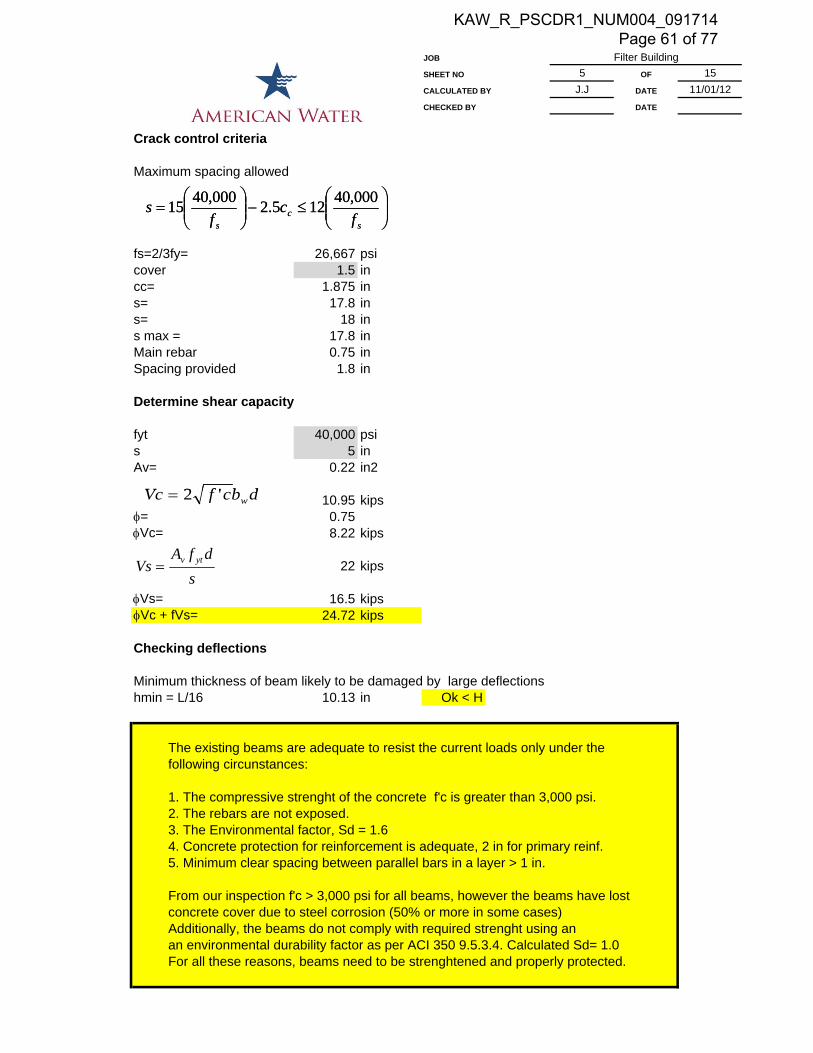
Crack control criteria
Maximum spacing allowed
fs=2/3fy= 26,667 psicover 1.5 incc= 1.875 ins= 17.8 ins= 18 ins max = 17.8 inMain rebar 0.75 inSpacing provided 1.8 in
Determine shear capacity
fyt 40,000 psis 5 inAv= 0.22 in2
Filter Building
dbfV '2
sc
s fc
fs
000,40125.2000,4015
10.95 kips= 0.75Vc= 8.22 kips
22 kips
Vs= 16.5 kipsVc + fVs= 24.72 kips
Checking deflections
Minimum thickness of beam likely to be damaged by large deflectionshmin = L/16 10.13 in Ok < H
The existing beams are adequate to resist the current loads only under thefollowing circunstances:
1. The compressive strenght of the concrete f'c is greater than 3,000 psi.2. The rebars are not exposed.3. The Environmental factor, Sd = 1.64. Concrete protection for reinforcement is adequate, 2 in for primary reinf.5. Minimum clear spacing between parallel bars in a layer > 1 in.
From our inspection f'c > 3,000 psi for all beams, however the beams have lost concrete cover due to steel corrosion (50% or more in some cases)Additionally, the beams do not comply with required strenght using anan environmental durability factor as per ACI 350 9.5.3.4. Calculated Sd= 1.0For all these reasons, beams need to be strenghtened and properly protected.
dbcfVc w'2
s
dfAVs ytv
sc
s fc
fs
000,40125.2000,4015
KAW_R_PSCDR1_NUM004_091714 Page 61 of 77

JOB
SHEET NO 6 OF 15CALCULATED BY J.J DATE 11/01/12CHECKED BY DATE
1.6 Checking Beam Capacity (Exposed rebars)Calculations were based on the information for beams B3 (Filters 16 to 23) and that only 50%of the lower rebars are in good conditions.
f'c= 3,000 psify= 40,000 psi
# Bar/ Size As layer 1 # Bar/ Size As layer 2row (in2) row (in2)1.5 6 0.66 2 5 0.62 1.28
Beam Geometry
bw= 8 inH= 14 inSlab thickness,t= 4 inCover= 2 in [@ centroid of the bar group]Span, L= 13.5 ftBeam spacing 2.58 ft
Filter Building
Layer 1 Layer 2As Total
(in2)
dt= 12.00 in
Determine effective width of the flange
Smallest of L/4 = 40.5 inbw+16t= 78 inbeam spacing 31 in
Use bef= 31 in
Determine depth of equivalent stress block a, as for a rectangular section
0.65 in Design as Rectangular Beam
Check :1= 0.85 [f'c<4,000 psi]ca1=a/1 = 0.76 inca1/dt= 0.06 Section is tension-controlled= 0.9
Actual steel ratio = 0.0034 NG < rminmin = 200/fy= 0.0050
Determine maximum capacity of the beam
Mn = Asfy(d-a/2) = 49.8 kip-ftMn= 44.8 kip-ft
efc
ys
bf
fAa '85.0
KAW_R_PSCDR1_NUM004_091714 Page 62 of 77

JOB
SHEET NO 7 OF 15CALCULATED BY J.J DATE 11/01/12CHECKED BY DATE
Crack control criteria
Maximum spacing allowed
fs=2/3fy= 26,667 psicover 1.5 incc= 1.875 ins= 17.8 ins= 18 ins max = 17.8 inMain rebar 0.75 inSpacing provided 1.8 in
Determine shear capacity
fyt 40,000 psi
Filter Building
sc
s fc
fs
000,40125.2000,4015
y ps 5 inAv= 0.22 in2
10.52 kips
= 0.75Vc= 7.89 kips
21.12 kips
Vs= 15.84 kips
Vc + fVs= 23.73 kips
Assuming that only the rebars at top layer are in good conditions and the bottom layer is at 50% of their capacity, the beams are working with a poor factor of safety and need to be braced immediately. This condition only applies to those beams that hold the water main with rebars exposed.
dbcfVc w'2
s
dfAVs ytv
sc
s fc
fs
000,40125.2000,4015
KAW_R_PSCDR1_NUM004_091714 Page 63 of 77
JOB
SHEET NO 8 OF 15CALCULATED BY J.J DATE 11/01/12CHECKED BY DATE
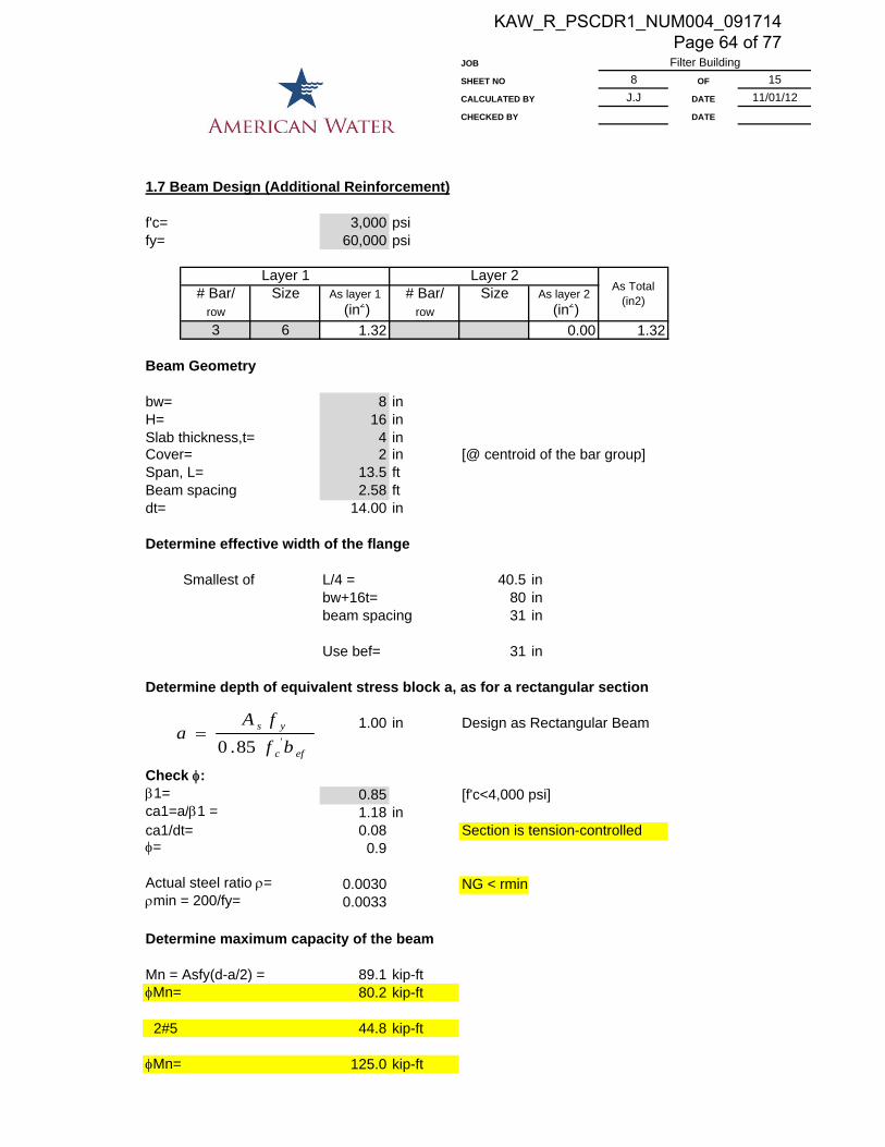
1.7 Beam Design (Additional Reinforcement)
f'c= 3,000 psify= 60,000 psi
# Bar/ Size As layer 1 # Bar/ Size As layer 2row (in2) row (in2)3 6 1.32 0.00 1.32
Beam Geometry
bw= 8 inH= 16 inSlab thickness,t= 4 inCover= 2 in [@ centroid of the bar group]Span, L= 13.5 ftBeam spacing 2.58 ftdt= 14.00 in
Filter Building
Layer 1 Layer 2As Total
(in2)
Determine effective width of the flange
Smallest of L/4 = 40.5 inbw+16t= 80 inbeam spacing 31 in
Use bef= 31 in
Determine depth of equivalent stress block a, as for a rectangular section
1.00 in Design as Rectangular Beam
Check :1= 0.85 [f'c<4,000 psi]ca1=a/1 = 1.18 inca1/dt= 0.08 Section is tension-controlled= 0.9
Actual steel ratio = 0.0030 NG < rminmin = 200/fy= 0.0033
Determine maximum capacity of the beam
Mn = Asfy(d-a/2) = 89.1 kip-ftMn= 80.2 kip-ft
2#5 44.8 kip-ft
Mn= 125.0 kip-ft
efc
ys
bf
fAa '85.0
KAW_R_PSCDR1_NUM004_091714 Page 64 of 77

JOB
SHEET NO 9 OF 15CALCULATED BY J.J DATE 11/01/12CHECKED BY DATE
Crack control criteria
Maximum spacing allowed
fs=2/3fy= 40,000 psicover 1.5 incc= 1.875 ins= 10.3 ins= 12 ins max = 10.3 inMain rebar 0.75 inSpacing provided 1.8 in
Determine shear capacity
fyt 60,000 psi
Filter Building
sc
s fc
fs
000,40125.2000,4015
y ps 5 inAv= 0.22 in2
12.27 kips
= 0.75Vc= 9.20 kips
36.96 kips
Vs= 27.72 kips
Vc + fVs= 36.92 kips
Strenghten of concrete beams is possible addin 3 #6 at the bottom o the existing beams
dbcfVc w'2
s
dfAVs ytv
sc
s fc
fs
000,40125.2000,4015
KAW_R_PSCDR1_NUM004_091714 Page 65 of 77
JOB
SHEET NO 10 OF 15CALCULATED BY J.J DATE 11/01/12CHECKED BY DATE
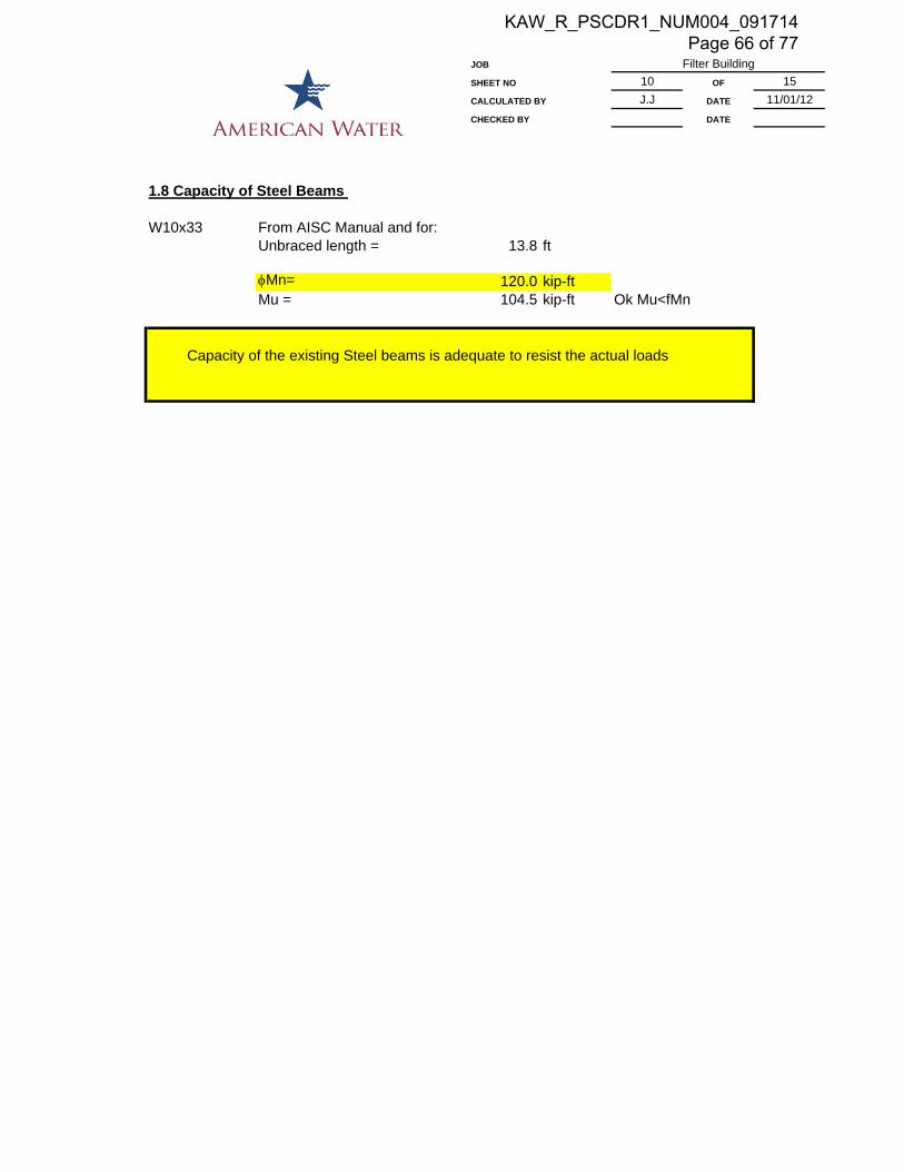
1.8 Capacity of Steel Beams
W10x33 From AISC Manual and for:Unbraced length = 13.8 ft
Mn= 120.0 kip-ftMu = 104.5 kip-ft Ok Mu<fMn
Capacity of the existing Steel beams is adequate to resist the actual loads
Filter Building
KAW_R_PSCDR1_NUM004_091714 Page 66 of 77

JOB
SHEET NO 11 OF 15CALCULATED BY J.J DATE 11/01/12CHECKED BY DATE
2.0 FILTER WALLS
2.1 Checking current design2.1.1 Soil condition. Interior empty tank
Surcharge Q = 0 psfh wall = 8.75 ftMin wall thickness L/16 = 6.5625 inWall thickness = 9 in
Ok> min
Ko = 0.4 soil = 110 pcfh fill = 8 ft
Soil pressuresq min = Ko.q = 0.4*0 0 psfq max = Ko(h+q) = 0.4*(110*8+0) 352 psf
Considering a fixed beam at the bottom and free at the top.
Filter Building
Ma triangular = wL2/8= 2,884 lb-ft/ftMa rectangular = wL2/8= 0 lb-ft/ftMa (soil) 34,603 lb-in/ft
2.1.2 Water condition + filter material. No Backfill
h (ft) g dry w (psf) P LocationGravel 152 pcf 1.75 89.6Sand 132 pcf 2.5 69.6
79.6 135.32 287.6 1.417Water 62.4 pcf 2.5 421.2
6.75Mwater = wL2/8 2,399 lb-ft/ftGravel and Sand 335 lb-ft/ftMa (water) 2,734 lb-ft/ft
Ma = 32,809 lb-ft/ft
M critical 34,603 lb-in/ft
Environmental factor Sd=fy/fs 1.41
fy= 40,000 psifs= 16,000 psi [ Severe environmental exposures]g= 1.6= 0.9
KAW_R_PSCDR1_NUM004_091714 Page 67 of 77
JOB
SHEET NO 12 OF 15CALCULATED BY J.J DATE 11/01/12CHECKED BY DATE
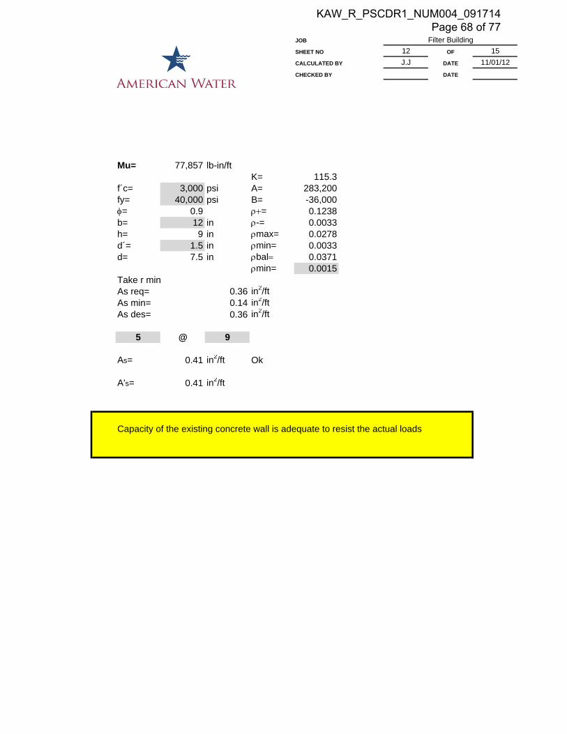
Mu= 77,857 lb-in/ftK= 115.3
f´c= 3,000 psi A= 283,200fy= 40,000 psi B= -36,000= 0.9 = 0.1238b= 12 in -= 0.0033h= 9 in max= 0.0278d´= 1.5 in min= 0.0033d= 7.5 in bal 0.0371
min= 0.0015Take r minAs req= 0.36 in2/ftAs min= 0.14 in2/ftAs des= 0.36 in2/ft
5 @ 9
Filter Building
@
As= 0.41 in2/ft Ok
A's= 0.41 in2/ft
Capacity of the existing concrete wall is adequate to resist the actual loads
KAW_R_PSCDR1_NUM004_091714 Page 68 of 77

JOB
SHEET NO 13 OF 15CALCULATED BY J.J DATE 11/01/12CHECKED BY DATE
2.2 Filter Walls (New construction)2.2.1 Soil condition. Interior empty tank
Surcharge Q = 0 psfh wall = 8.75 ftMin wall thickness L/16 = 6.5625 inWall thickness = 10 in
Ok> min
Ko = 0.4 soil = 110 pcfh fill = 8.75 ft
Soil pressuresq min = Ko.q = 0.4*0 0 psfq max = Ko(h+q) = 0.4*(110*8.75+0) 385 psf
Considering a fixed beam at the bottom and free at the top.
Filter Building
Ma triangular = wL2/8= 3,773 lb-ft/ftMa rectangular = wL2/8= 0 lb-ft/ftMa (soil) 45,276 lb-in/ft
2.2.2 Water condition + filter material
h (ft) g dry w (psf) P LocationGravel 152 pcf 1.75 89.6Sand 132 pcf 2.5 69.6
79.6 135.32 287.6 1.417Water 62.4 pcf 2.5 421.2
6.75Mwater = wL2/8 2,399 lb-ft/ftGravel and Sand 341 lb-ft/ftMa (water) 2,740 lb-ft/ft
Ma = 32,883 lb-ft/ft
M critical 45,276 lb-in/ft
Environmental factor Sd=fy/fs 1.69
fy= 60,000 psifs= 20,000 psi [ Severe environmental exposures]g= 1.6= 0.9
KAW_R_PSCDR1_NUM004_091714 Page 69 of 77

JOB
SHEET NO 14 OF 15CALCULATED BY J.J DATE 11/01/12CHECKED BY DATE
Mu= 122,245 lb-in/ftK= 207.9
f´c= 3,000 psi A= 637,200fy= 60,000 psi B= -54,000= 0.9 = 0.0807b= 12 in -= 0.0040h= 10 in max= 0.0160d´= 3 in min= 0.0033d= 7 in bal 0.0214
min= 0.0015Take rAs req= 0.49 in2/ftAs min= 0.13 in2/ftAs des= 0.49 in2/ft
6 @ 8
Filter Building
@
As= 0.66 in2/ft Ok
A's= 0.66 in2/ft
Use 10" concrete wall with #6@8" E.F.
KAW_R_PSCDR1_NUM004_091714 Page 70 of 77

JOB
SHEET NO 15 OF 15CALCULATED BY J.J DATE 11/01/12CHECKED BY DATE
2.2.3 Checking deflections (ACI 9.5.2.3)
Es= psiEc= psi
fr = 410.8 psiIg = b.h3/12 =1/12*12*10^3 1,000 in4
Filter Building
29,000,0003,122,019
cffy
IfM
IM
MI
M
MIe
rt
grcr
cra
crg
a
cr
'5.7;
133
gyt = thickness/2 = 5 inMcr = =410.79*1000/5 82,158 lb-inMa = =45276*12 45,276 lb-in
From Table 10-2 PCA Notes on ACI 318-05
n = Es/Ec =29000000/3122018.58 9.3B = b/(nAs) =12/(0.66*9.29) 1.96r =(9.29-1)*0.66/(9.29*0.66) 0.89kd 2.32Icr =1/3*12*2.32^3+9.29*0.66*(7-2.32)^2+(9.29-1)*0.66*(2.32-3)^2 186.8 in4
Ie =(82158.38/45276)^3*1000+(1-(82158.38/45276)^3)*186.75 5046 in4Ie > Ig Take Ie as Ig 1000 in4
1 =(0*(8.75)^4)/(8*3122018.58*1000)*(12^3) 0.0000 in2 =((385-0)*(8.75)^4)/(30*3122018.58*1000)*12^3 0.0416 in
total = 0.042 in Ok < Allow
allow = 8.75*12/360 0.29 in L/360
KAW_R_PSCDR1_NUM004_091714 Page 71 of 77

APPENDIX B
KAW_R_PSCDR1_NUM004_091714 Page 72 of 77

KAW_R_PSCDR1_NUM004_091714 Page 73 of 77

KAW_R_PSCDR1_NUM004_091714 Page 74 of 77

KAW_R_PSCDR1_NUM004_091714 Page 75 of 77

KAW_R_PSCDR1_NUM004_091714 Page 76 of 77

8.6 COST ESTIMATES
.
48
KAW_R_PSCDR1_NUM004_091714 Page 77 of 77