APPROVAL SHEET ISSUED CHECKED APPROVED DATE : 31. May. ‘01 REVISION No. 1.0 MESSRS. Receipt Stamp...
18
APPROVAL SHEET ISSUED CHECKED APPROVED DATE : 31. May. ‘01 REVISION No. 1.0 MESSRS. Receipt Stamp C&B Technology Inc. DESCRIPTION : CCD Color Board Camera ET MODEL NO. : CNB - EN300, 350,300C,350C ( NTSC ) CNB - EP300,350,300C,350C ( PAL )
-
Upload
christal-robbins -
Category
Documents
-
view
213 -
download
0
Transcript of APPROVAL SHEET ISSUED CHECKED APPROVED DATE : 31. May. ‘01 REVISION No. 1.0 MESSRS. Receipt Stamp...
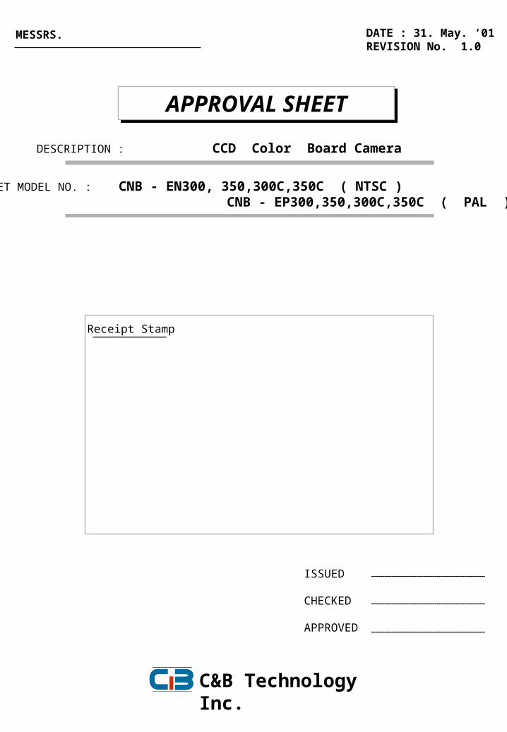
APPROVAL SHEETAPPROVAL SHEET
ISSUED
CHECKED
APPROVED
DATE : 31. May. ‘01REVISION No. 1.0
MESSRS.
Receipt Stamp
C&B Technology Inc.
DESCRIPTION : CCD Color Board Camera
SET MODEL NO. : CNB - EN300, 350,300C,350C ( NTSC ) CNB - EP300,350,300C,350C ( PAL )
REVISION CONTENTS
NO REVISION CONTENTS REVISION DATE Page REMARKS
CNB-EN300/300C/350350C, EP300/300C/350350C Specifications
C&B Technology Inc.

1/10
CONTENTS
1. SPECIFICATIONS------------------------------------------------------------ 2
2. MEASUREMENT SPECIFICATIONS------------------------------------ 4
3. ENVIRONMENT CONDITION AND TEST----------------------------- 4
4. INTERFACE------------------------------------------------------------------- 5
5. RECOMMENDED CIRCUIT FOR LOCAL CONTROLS------------ 6
6. APPEARANCE---------------------------------------------------------------- 9
7. PACKING METHOD--------------------------------------------------------- 10
PAGE
CCD COLOR BOARD CAMERA
CNB – E N 3 0 0 C V1 2 3 4
1 N : NTSCP : PAL
2 0 : HIGH 5 : NORMAL
3 C : C/CS MOUNT LENSP : PIN HOLE LENSV : VARI-FOCAL LENS
4 V : VIDEO IRISD : DC IRIS
C&B Technology Inc.
CNB-EN300/300C/350350C, EP300/300C/350350C Specifications

1. SPECIFICATIONS
Signal System NTSC ( CNB - EN300/C ) PAL ( CNB - EP300/C )
Scanning System 2 : 1 Interlace
Scanning Frequency ( H ) 15.734 KHz 15.625 KHz
59.94 Hz 50 Hz
Image Sensor 1 / 3 Inch Solid State Interline CCD Image Sensor
Total Pixels No.
Effective Pixels No.
Scanning Frequency ( V )
SONY
REMARKS
811 (H) X 508 (V) 410K 795 (H) X 596 (V) 470K
768 (H) X 494 (V) 380K 752 (H) X 582 (V) 440K
Signal System NTSC ( CNB - EN350/C) PAL ( CNB - EP350/C )
Scanning System 2 : 1 Interlace
Scanning Frequency ( H ) 15.734 KHz 15.625 KHz
59.94 Hz 50 Hz
Image Sensor 1 / 3 Inch Solid State Interline CCD Image Sensor
Total Pixels No.
Effective Pixels No.
Scanning Frequency ( V )
SONY
REMARKS
537 (H) X 505 (V) 270K 537 (H) X 597 (V) 320K
510 (H) X 492 (V) 250K 500 (H) X 582 (V) 290K
1) Angle of view at Diagonal 88 。 ( f= 3.8 mm ) 60 。 ( f= 5.8 mm )
2) Signal Process Digital Signal Process
3) Sync System Internal / External
4) Camera Function
a) Digital Zoom ON / Off ( 3 times )
b) Video Focus Focus free from 0.1m( f= 3.8 mm ) ,0.4m(f= 5.8 mm ) to ∞
2/10
c) White Balance Auto / Indoor / Outdoor / Push Auto / Manual ( R&B Gain Level UP/Down ) Special ( R or B Gain Level Control )
c) Shutter Speed Auto / Manual (1/60 ~ 1/ 10000 ( NTSC) / 1/50 ~ 1/10000 (PAL) ) d) Iris Control Fixed / Manual ( Video Iris, DC Iris Optional)
e) Gain Control Auto / Off
f) Sharpness Manual ( Sharpness UP ~ Down )
g) Brightness Manual ( Brightness UP ~ Down ) h) Negative Off / On
i) Flickerless Off / On ( 1 / 100 sec Shutter Set (NTSC) / 1 / 120 sec Shutter Set (PAL) )
j) Back Light Auto / Off / On
“ Bold : Default Mode ”
C&B Technology Inc.
CNB-EN300/300C/350350C, EP300/300C/350350C Specifications
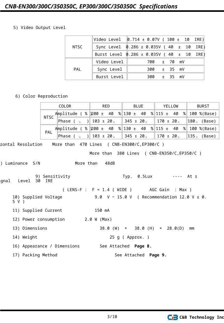
5) Video Output Level
NTSC
Video Level
Sync Level
0.714 ± 0.07V ( 100 ± 10 IRE)
0.286 ± 0.035V ( 40 ± 10 IRE)
Burst Level 0.286 ± 0.035V ( 40 ± 10 IRE)
700 ± 70 mV
300 ± 35 mV
300 ± 35 mV
PAL
Video Level
Sync Level
Burst Level
6) Color Reproduction
NTSCAmplitude ( % )
Phase ( 。 )
100 %(Base)
180 。 (Base)
RED BLUE YELLOW BURSTCOLOR
200 ± 40 %
103 ± 20 。
PALAmplitude ( % )
Phase ( 。 )
100 %(Base)
135 。 (Base)
130 ± 40 %
345 ± 20 。 115 ± 40 %
170 ± 20 。
200 ± 40 %
103 ± 20 。 130 ± 40 %
345 ± 20 。 115 ± 40 %
170 ± 20 。
9) Sensitivity Typ. 0.5Lux ---- At signal Level 30 IRE
( LENS-F : F = 1.4 ( WIDE ) AGC Gain : Max )
7) Horizontal Resolution More than 470 Lines ( CNB-EN300/C,EP300/C ) More than 380 Lines ( CNB-EN350/C,EP350/C )
8) Luminance S/N More than 48dB
3/10
10) Supplied Voltage 9.0 V ~ 15.0 V ( Recommendation 12.0 V ± 0.5 V )
11) Supplied Current 150 mA
12) Power consumption 2.0 W (Max)
13) Dimensions 38.0 (W) × 38.0 (H) × 28.0(D) mm
14) Weight 25 g ( Approx. )
16) Appearance / Dimensions See Attached Page 8.
17) Packing Method See Attached Page 9.
C&B Technology Inc.
CNB-EN300/300C/350350C, EP300/300C/350350C Specifications
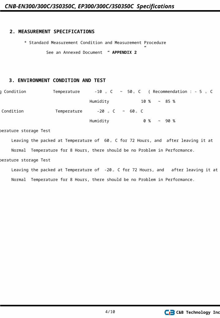
2. MEASUREMENT SPECIFICATIONS
* Standard Measurement Condition and Measurement Procedure
See an Annexed Document “ APPENDIX 2 ”
4/10
1) Operating Condition Temperature -10 。 C ~ 50 。 C ( Recommendation : - 5 。 C ~ 40 。 C )
Humidity 10 % 85 %∼
2) Storage Condition Temperature -20 。 C ~ 60 。 C Humidity 0 % 90 %∼
3) High Temperature storage Test
Leaving the packed at Temperature of 60 。 C for 72 Hours, and after leaving it at
Normal Temperature for 8 Hours, there should be no Problem in Performance.
4) Low Temperature storage Test
Leaving the packed at Temperature of -20 。 C for 72 Hours, and after leaving it at
Normal Temperature for 8 Hours, there should be no Problem in Performance.
3. ENVIRONMENT CONDITION AND TEST
C&B Technology Inc.
CNB-EN300/300C/350350C, EP300/300C/350350C Specifications
5V
GND
NAMEPIN No.
1
2
3
4
I/O LEVEL
RD(For RS-232C)
TD(For RS- 232C)
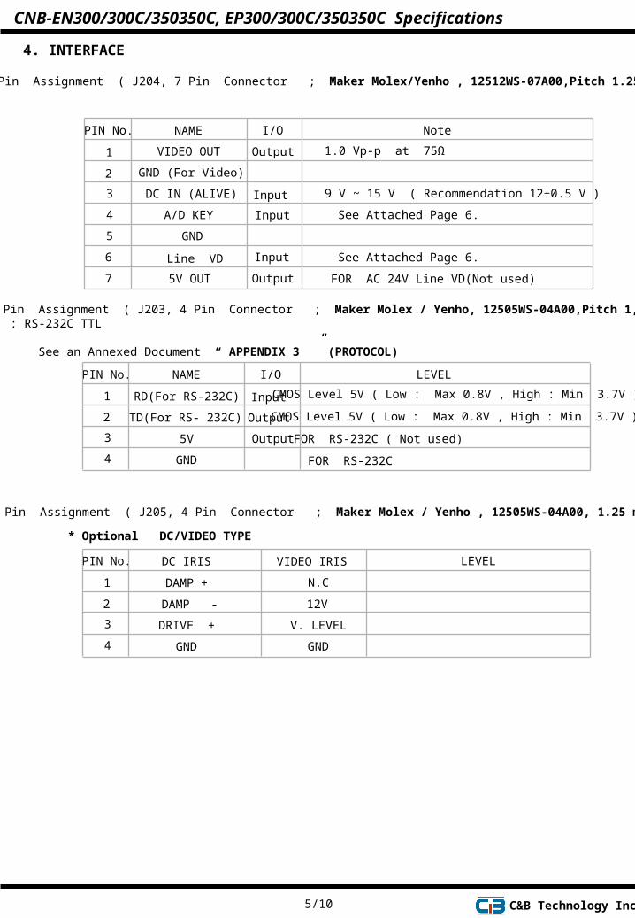
CMOS Level 5V ( Low : Max 0.8V , High : Min 3.7V )Input
Output CMOS Level 5V ( Low : Max 0.8V , High : Min 3.7V )
2) Pin Assignment ( J203, 4 Pin Connector ; Maker Molex / Yenho, 12505WS-04A00,Pitch 1,25 mm ) : RS-232C TTL See an Annexed Document “ APPENDIX 3 ” (PROTOCOL)
Output
DRIVE +
GND
DC IRISPIN No.
1
2
3
4
LEVEL
DAMP +
DAMP -
3) Pin Assignment ( J205, 4 Pin Connector ; Maker Molex / Yenho , 12505WS-04A00, 1.25 mm )
VIDEO IRIS
V. LEVEL
GND
N.C
12V
* Optional DC/VIDEO TYPE
FOR RS-232C ( Not used)
FOR RS-232C
5/10 C&B Technology Inc.
4. INTERFACE
1) Pin Assignment ( J204, 7 Pin Connector ; Maker Molex/Yenho , 12512WS-07A00,Pitch 1.25 mm )
A/D KEY
GND (For Video)
DC IN (ALIVE)
VIDEO OUT
GND
9 V ~ 15 V ( Recommendation 12±0.5 V )
NAMEPIN No.
1
2
3
4
5
6
7
I/O
Input
Note
Output
Input
5V OUT
Line VD Input
Output FOR AC 24V Line VD(Not used)
CNB-EN300/300C/350350C, EP300/300C/350350C Specifications
1.0 Vp-p at 75Ω
See Attached Page 6.
See Attached Page 6.
6/10
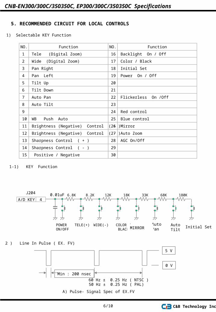
5. RECOMMENDED CIRCUIT FOR LOCAL CONTROLS
1) Selectable KEY Function
NO. Function NO. Function
1 Tele (Digital Zoom)
21
2 Wide (Digital Zoom)
22 Flickerless On /Off
3 Pan Right
23
4 Pan Left
24 Red control
5 Tilt Up
25 Blue control
6 Tilt Down
26 Mirror
7 Auto Pan
27 Auto Zoom
8 Auto Tilt
28 AGC On/Off
9
29
10 WB Push Auto
30
11 Brightness (Negative) Control ( + )
12 Brightness (Negative) Control ( - )
13 Sharpness Control ( + )
14 Sharpness Control ( - )
15 Positive / Negative
16 Backlight On / Off
17 Color / Black
18 Initial Set
19 Power On / Off
20
1-1) KEY Function
6.8K 8.2K 12K 18K 33K 68K 180K0.01uFA/D KEY 4
J204
C&B Technology Inc.
TELE(+) WIDE(-)POWERON/OFF
COLOR / BLACK
2 ) Line In Pulse ( EX. FV)
Min : 200 nsec
60 Hz ± 0.25 Hz ( NTSC )50 Hz ± 0.25 Hz ( PAL)
5 V
0 V
A) Pulse- Signal Spec of EX.FV
Initial Set Auto Pan
AutoTiltMIRROR
CNB-EN300/300C/350350C, EP300/300C/350350C Specifications
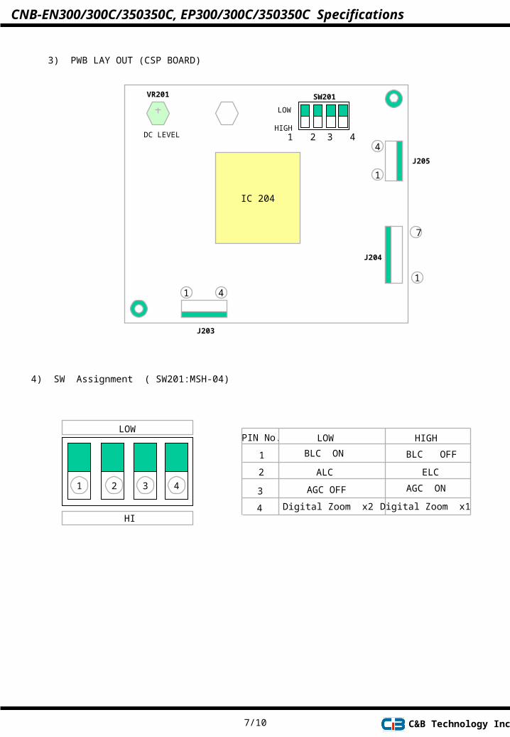
3) PWB LAY OUT (CSP BOARD)
IC 204
1 2 3 4 HIGH
LOW
SW201
1 4
J203
1
4
J205
1
7
J204
VR201
DC LEVEL
C&B Technology Inc.
4) SW Assignment ( SW201:MSH-04)
LOW
HI
1 2 3 4
LOWPIN No.
1
2 ALC
HIGH
ELC
Digital Zoom x1
3
4
BLC ON
AGC OFF AGC ON
BLC OFF
Digital Zoom x2
7/10
CNB-EN300/300C/350350C, EP300/300C/350350C Specifications

PIN No. 3 4
HIGH HIGH
HIGH
HIGH
LOWLOW
LOW
LOW
FUNCTION
Digital Zoom X1
Digital Zoom X2
Digital Zoom X3
Auto ( X1 ~ X3 ~X1 )
CNB-EN300/300C/350350C, EP300/300C/350350C Specifications
C&B Technology Inc.8/10
LOWPIN No.
1
2
HIGH
3
4
LOWPIN No.
1
2
HIGH
3
4
Option 3
4 - 1) Selectable SW Function
LOWPIN No.
1
2
HIGH
3
4
LOWPIN No.
1
2
3
4
Option 1
Option 4
MIRROR ON MIRROR OFF
ALC ELC
Zoom 1 Zoom 1
Zoom 2 Zoom 2
Option 2
BLC ON BLC OFF
ALC ELC
Flickerless ON Flickerless OFF
Digital Zoom x2 Digital Zoom OFF
BLC ON BLC OFF
ALC ELC
Flickerless ON Flickerless OFF
AGC ON AGC OFF
BLC ON BLC OFF
ALC ELC
MIRROR ON MIRROR OFF
Digital Zoom x2 Digital Zoom OFF
HIGH
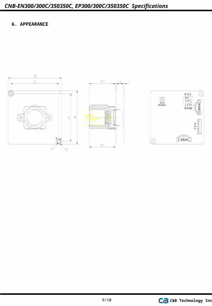
6. APPEARANCE
9/10 C&B Technology Inc.
H=4.2
MHS04
31 2 4
H=2.5
ON
H=4.8
1
8.2
* 8.8
*3.2
71/
4"
NO
R나
라
MVR32H=3
H=4.81
B.F.L. 5.6focal length3.6
IMA
GE P
LAN
O
CNB-EN300/300C/350350C, EP300/300C/350350C Specifications

7. PACKING METHOD
10/10 C&B Technology Inc.
5x4
5x4
5x4
5x4
5x4
CNB-EN300/300C/350350C, EP300/300C/350350C Specifications
APPENDIX 2
CNB - EN300/C, 350/C CNB - EP300/C, 350/C
DATE : 17. May. ‘01REVISION No. 0.9
MODEL
Measurement SpecificationsMeasurement Specifications
C&B Technology Inc.
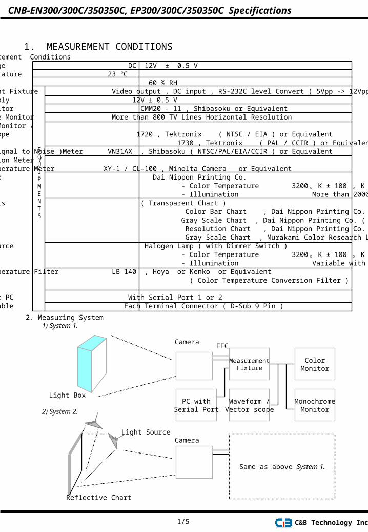
1. MEASUREMENT CONDITIONS1) Standard Measurement Conditions Supplied Voltage DC 12V ± 0.5 V Ambient Temperature 23 ℃ Humidity 60 % RH Measurement Fixture Video output , DC input , RS-232C level Convert ( 5Vpp -> 12Vpp) Power Supply 12V ± 0.5 V Color Monitor CMM20 - 11 , Shibasoku or Equivalent Monochrome Monitor More than 800 TV Lines Horizontal Resolution Waveform Monitor / Vector Scope 1720 , Tektronix ( NTSC / EIA ) or Equivalent 1730 , Tektronix ( PAL / CCIR ) or Equivalent S / N ( Signal to Noise )Meter VN31AX , Shibasoku ( NTSC/PAL/EIA/CCIR ) or Equivalent Illumination Meter / Color Temperature Meter XY-1 / CL-100 , Minolta Camera or Equivalent Light Box Dai Nippon Printing Co. - Color Temperature 3200 。 K ± 100 。 K - Illumination More than 2000 Lux Test Charts ( Transparent Chart ) Color Bar Chart , Dai Nippon Printing Co. Gray Scale Chart , Dai Nippon Printing Co. ( Gamma 0.45 ) Resolution Chart , Dai Nippon Printing Co. ( Reflective Chart ) Gray Scale Chart , Murakami Color Research Lab Light Source Halogen Lamp ( with Dimmer Switch ) - Color Temperature 3200 。 K ± 100 。 K - Illumination Variable with Dimmer Color Temperature Filter LB 140 , Hoya or Kenko or Equivalent ( Color Temperature Conversion Filter ) Adjustment PC With Serial Port 1 or 2 RS-232C Cable Each Terminal Connector ( D-Sub 9 Pin )
2. Measuring System1) System 1.
MeasurementFixture
Light Box
ColorMonitor
MonochromeMonitor
Waveform /Vector scope
FFC
PC withSerial Port2) System 2.
Light Source
Same as above System 1.
Camera
Camera
Reflective Chart
EQUIPMENTS
1/5 C&B Technology Inc.
CNB-EN300/300C/350350C, EP300/300C/350350C Specifications
2. MEASUREMENT PROCEDURE
1. VIDEO OUPUT LEVELTEST CONDITIONS
MEASURING SYSTEM
Refer to “ 1. MEASUREMENT CONDITIONS “
System 1.
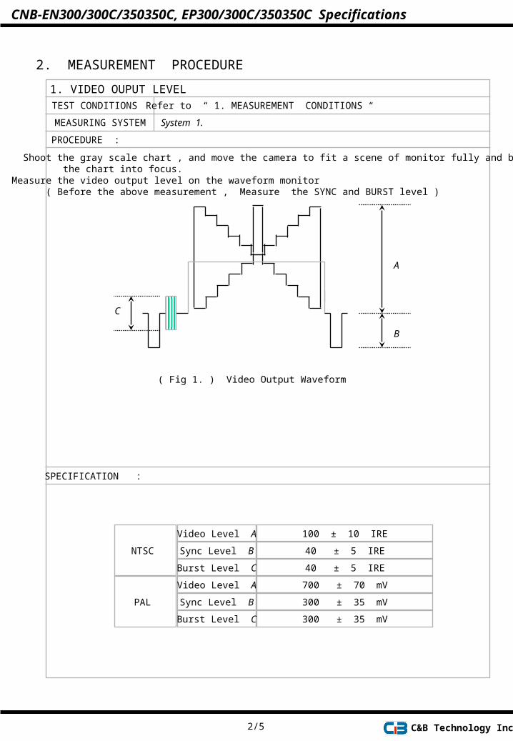
PROCEDURE :
1. Shoot the gray scale chart , and move the camera to fit a scene of monitor fully and bring the chart into focus.2. Measure the video output level on the waveform monitor ( Before the above measurement , Measure the SYNC and BURST level )
A
B
C
( Fig 1. ) Video Output Waveform
SPECIFICATION :
NTSC
Video Level A
Sync Level B
100 ± 10 IRE
40 ± 5 IRE
Burst Level C 40 ± 5 IRE
700 ± 70 mV
300 ± 35 mV
300 ± 35 mV
PAL
Video Level A
Sync Level B
Burst Level C
2/5 C&B Technology Inc.
CNB-EN300/300C/350350C, EP300/300C/350350C Specifications
2. COLOR REPRODUCTIONTEST CONDITIONS
MEASURING SYSTEM
Refer to “ 1. MEASUREMENT CONDITIONS “
System 1.
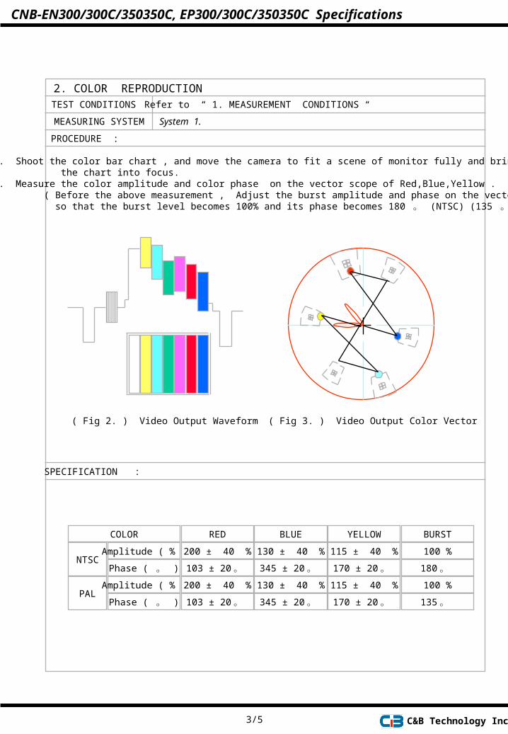
PROCEDURE :
1. Shoot the color bar chart , and move the camera to fit a scene of monitor fully and bring the chart into focus. 2. Measure the color amplitude and color phase on the vector scope of Red,Blue,Yellow . ( Before the above measurement , Adjust the burst amplitude and phase on the vectorscope so that the burst level becomes 100% and its phase becomes 180 。 (NTSC) (135 。 PAL)
( Fig 2. ) Video Output Waveform
SPECIFICATION :
NTSCAmplitude ( % )
Phase ( 。 )
( Fig 3. ) Video Output Color Vector
100 %
180 。
RED BLUE YELLOW BURSTCOLOR
200 ± 40 %
103 ± 20 。
PALAmplitude ( % )
Phase ( 。 )
100 %
135 。
130 ± 40 %
345 ± 20 。 115 ± 40 %
170 ± 20 。 200 ± 40 %
103 ± 20 。 130 ± 40 %
345 ± 20 。 115 ± 40 %
170 ± 20 。
3/5 C&B Technology Inc.
CNB-EN300/300C/350350C, EP300/300C/350350C Specifications

3. LUMINANCE S / NTEST CONDITIONS
MEASURING SYSTEM
Refer to “ 1. MEASUREMENT CONDITIONS “
System 1.
PROCEDURE :
1. Shoot the light box , and move the camera to fit a scene of monitor fully and bring the chart into focus. 2. The noise meter settings are ; Input level : Preset High Pass Filter : 100KHz Low Pass Filter : 4.2 MHz Sub-carrier Trap : On Weighting : On Sag & Hue Comp. : Optimum 3. Measure the maximum S/N on the noise meter .
SPECIFICATION :
NTSC : More than 48 dBPAL : More than 48 dB
4. HORIZONTAL RESOLUTION
TEST CONDITIONS
MEASURING SYSTEM
Refer to “ 1. MEASUREMENT CONDITIONS “
System 1.
PROCEDURE :
1. Shoot the resolution chart , and move the camera to fit a scene of monitor fully and bring the chart into focus. 2. Adjust the brightness and contrast of the B/W monitor so that each steps of resolution chart can be observed . 3. Change the scan size of monitor to underscan. 4. The reference arrows on the resolution chart are positioned at theedge of the underscanned picture . 5. Change the scan size of monitor from underscan to overscan . 6. Measure the maximum horizontal resolution on the picture .
SPECIFICATION :
More than 470 TV Lines ( High Resolution ) More than 380 TV Lines ( Normal Resolution )
4/5 C&B Technology Inc.
CNB-EN300/300C/350350C, EP300/300C/350350C Specifications
5. LOW LUMINANCE SENSITIVITYTEST CONDITIONS
MEASURING SYSTEM
Refer to “ 1. MEASUREMENT CONDITIONS “
System 2.
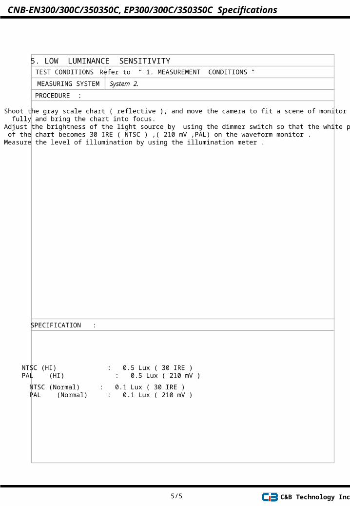
PROCEDURE :
1. Shoot the gray scale chart ( reflective ), and move the camera to fit a scene of monitor fully and bring the chart into focus. 2. Adjust the brightness of the light source by using the dimmer switch so that the white peak level of the chart becomes 30 IRE ( NTSC ) ,( 210 mV ,PAL) on the waveform monitor . 3. Measure the level of illumination by using the illumination meter .
SPECIFICATION :
5/5
NTSC (HI) : 0.5 Lux ( 30 IRE )PAL (HI) : 0.5 Lux ( 210 mV )
NTSC (Normal) : 0.1 Lux ( 30 IRE )PAL (Normal) : 0.1 Lux ( 210 mV )
C&B Technology Inc.
CNB-EN300/300C/350350C, EP300/300C/350350C Specifications