APPLICATION GUIDE - INCLINOMETERS · MEMS inclinometers employ ‘State of the Art’ MEMS sensor...
22
V1.0 January 2014 1.0 General description An inclinometer measures TILT (the measurand) which is used in several calculations (computations) to quantify displacement and deflections of slopes, embankments, and structures. There are two types of inclinometer:- • Portable • In-place 1.1 Portable inclinometer The portable system comprises of several components as follows:- 1.) Wheeled probe 2.) Reel 3.) Cable 4.) Readout 5.) Accessories including cable gates, battery chargers, spare batteries l 5 2 4 1 3 APPLICATION GUIDE - INCLINOMETERS NOTE: This application guide is intended only to give an overview of the several types of inclinometers including where and why they are used, how they are typically installed and how data is obtained from them. Please note it is not a definitive guide.
Transcript of APPLICATION GUIDE - INCLINOMETERS · MEMS inclinometers employ ‘State of the Art’ MEMS sensor...

V1.0 January 2014
1.0 General description An inclinometer measures TILT (the measurand) which is used in several calculations (computations) to quantify displacement and deflections of slopes, embankments, and structures. There are two types of inclinometer:- • Portable • In-place 1.1 Portable inclinometer The portable system comprises of several components as follows:- 1.) Wheeled probe 2.) Reel 3.) Cable 4.) Readout 5.) Accessories including cable gates, battery chargers, spare batteries l
5
2
4
1
3
APPLICATION GUIDE - INCLINOMETERS
NOTE: This application guide is intended only to give an overview of the several types of inclinometers including where and why they are used, how they are typically installed and how data is obtained from them. Please note it is not a definitive guide.
2 V1.0 January 2014
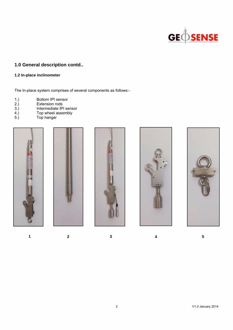
1.0 General description contd.. 1.2 In-place inclinometer The In-place system comprises of several components as follows:- 1.) Bottom IPI sensor 2.) Extension rods 3.) Intermediate IPI sensor 4.) Top wheel assembly 5.) Top hanger
1 2 3 4 5
3 V1.0 January 2014
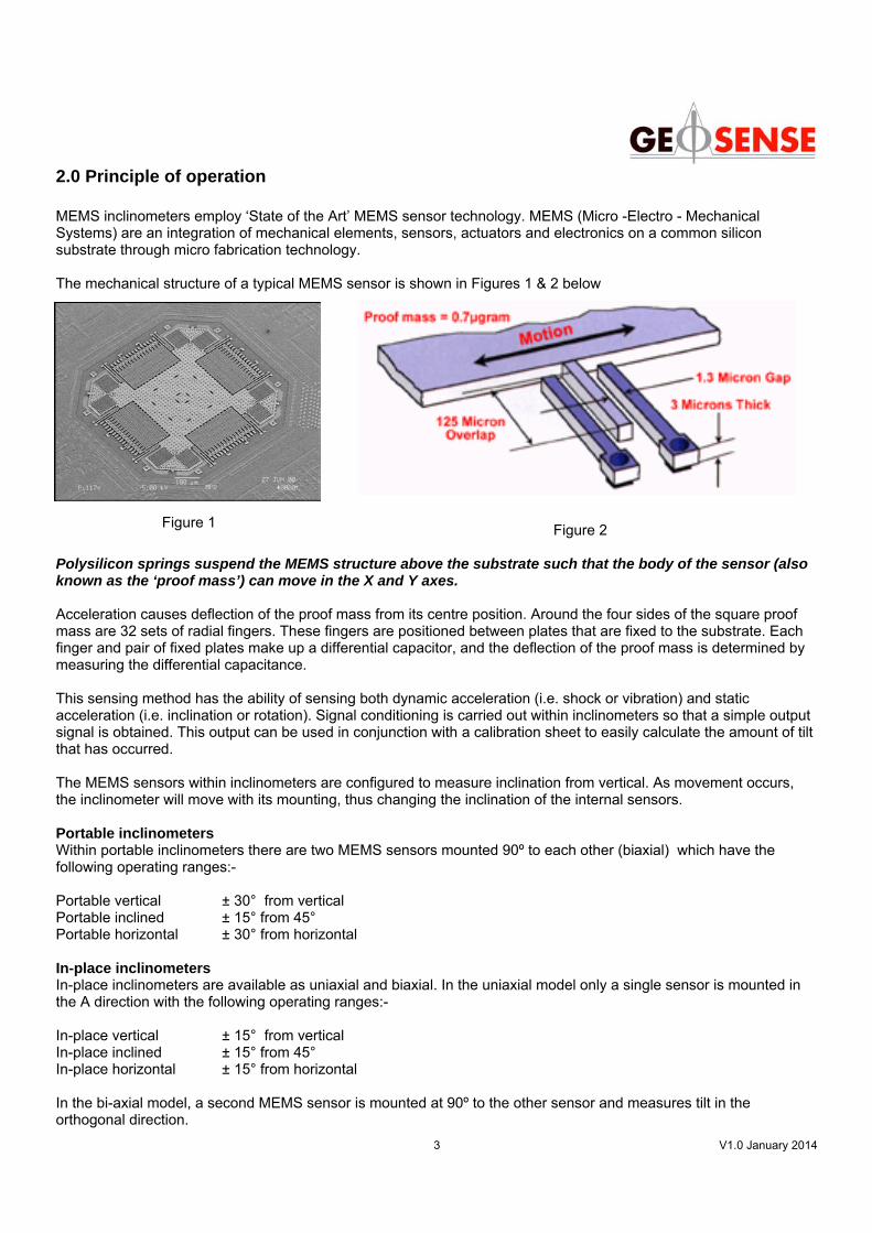
2.0 Principle of operation MEMS inclinometers employ ‘State of the Art’ MEMS sensor technology. MEMS (Micro -Electro - Mechanical Systems) are an integration of mechanical elements, sensors, actuators and electronics on a common silicon substrate through micro fabrication technology. The mechanical structure of a typical MEMS sensor is shown in Figures 1 & 2 below
Polysilicon springs suspend the MEMS structure above the substrate such that the body of the sensor (also known as the ‘proof mass’) can move in the X and Y axes. Acceleration causes deflection of the proof mass from its centre position. Around the four sides of the square proof mass are 32 sets of radial fingers. These fingers are positioned between plates that are fixed to the substrate. Each finger and pair of fixed plates make up a differential capacitor, and the deflection of the proof mass is determined by measuring the differential capacitance. This sensing method has the ability of sensing both dynamic acceleration (i.e. shock or vibration) and static acceleration (i.e. inclination or rotation). Signal conditioning is carried out within inclinometers so that a simple output signal is obtained. This output can be used in conjunction with a calibration sheet to easily calculate the amount of tilt that has occurred. The MEMS sensors within inclinometers are configured to measure inclination from vertical. As movement occurs, the inclinometer will move with its mounting, thus changing the inclination of the internal sensors. Portable inclinometers Within portable inclinometers there are two MEMS sensors mounted 90º to each other (biaxial) which have the following operating ranges:- Portable vertical ± 30° from vertical Portable inclined ± 15° from 45° Portable horizontal ± 30° from horizontal In-place inclinometers In-place inclinometers are available as uniaxial and biaxial. In the uniaxial model only a single sensor is mounted in the A direction with the following operating ranges:- In-place vertical ± 15° from vertical In-place inclined ± 15° from 45° In-place horizontal ± 15° from horizontal In the bi-axial model, a second MEMS sensor is mounted at 90º to the other sensor and measures tilt in the orthogonal direction.
Figure 1 Figure 2
4 V1.0 January 2014
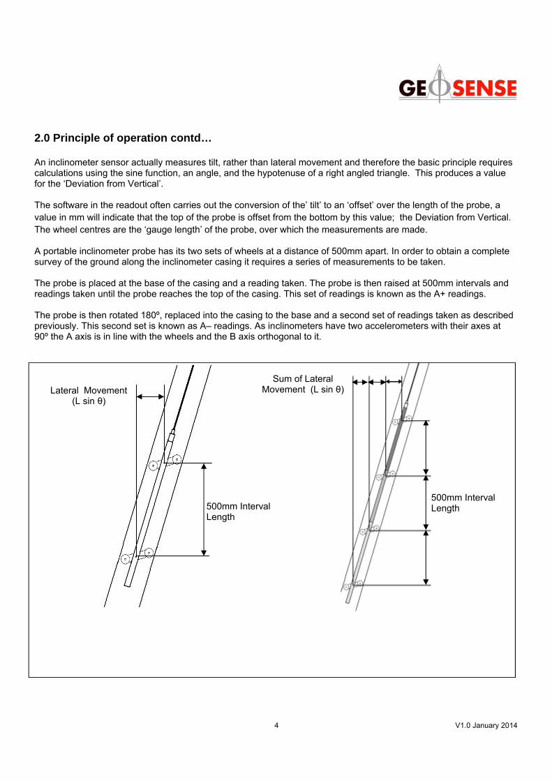
500mm Interval Length
Lateral Movement (L sin θ)
500mm Interval Length
Sum of Lateral Movement (L sin θ)
2.0 Principle of operation contd… An inclinometer sensor actually measures tilt, rather than lateral movement and therefore the basic principle requires calculations using the sine function, an angle, and the hypotenuse of a right angled triangle. This produces a value for the ‘Deviation from Vertical’. The software in the readout often carries out the conversion of the’ tilt’ to an ‘offset’ over the length of the probe, a value in mm will indicate that the top of the probe is offset from the bottom by this value; the Deviation from Vertical. The wheel centres are the ‘gauge length’ of the probe, over which the measurements are made.
A portable inclinometer probe has its two sets of wheels at a distance of 500mm apart. In order to obtain a complete survey of the ground along the inclinometer casing it requires a series of measurements to be taken. The probe is placed at the base of the casing and a reading taken. The probe is then raised at 500mm intervals and readings taken until the probe reaches the top of the casing. This set of readings is known as the A+ readings. The probe is then rotated 180º, replaced into the casing to the base and a second set of readings taken as described previously. This second set is known as A– readings. As inclinometers have two accelerometers with their axes at 90º the A axis is in line with the wheels and the B axis orthogonal to it.
5 V1.0 January 2014
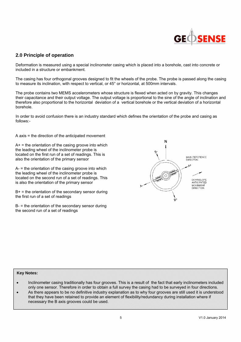
2.0 Principle of operation Deformation is measured using a special inclinometer casing which is placed into a borehole, cast into concrete or included in a structure or embankment. The casing has four orthogonal grooves designed to fit the wheels of the probe. The probe is passed along the casing to measure its inclination, with respect to vertical, or 45° or horizontal, at 500mm intervals. The probe contains two MEMS accelerometers whose structure is flexed when acted on by gravity. This changes their capacitance and their output voltage. The output voltage is proportional to the sine of the angle of inclination and therefore also proportional to the horizontal deviation of a vertical borehole or the vertical deviation of a horizontal borehole. In order to avoid confusion there is an industry standard which defines the orientation of the probe and casing as follows:-
A axis = the direction of the anticipated movement A+ = the orientation of the casing groove into which the leading wheel of the inclinometer probe is located on the first run of a set of readings. This is also the orientation of the primary sensor A- = the orientation of the casing groove into which the leading wheel of the inclinometer probe is located on the second run of a set of readings. This is also the orientation of the primary sensor B+ = the orientation of the secondary sensor during the first run of a set of readings B- = the orientation of the secondary sensor during the second run of a set of readings
Key Notes: • Inclinometer casing traditionally has four grooves. This is a result of the fact that early inclinometers included
only one sensor. Therefore in order to obtain a full survey the casing had to be surveyed in four directions. • As there appears to be no definitive industry explanation as to why four grooves are still used it is understood
that they have been retained to provide an element of flexibility/redundancy during installation where if necessary the B axis grooves could be used.

6 V1.0 January 2014
3.0 Industry convention In order to avoid confusion as to the direction of tilt of the probe, a positive value indicates that the top of the probe is tilting in the direction of the “leading wheel” (upper wheel) as illustrated below.
Probe orientated towards A+
- ve Reading +ve
+ ve Reading - ve
Leading/upper wheel
Probe orientated towards A-
Leading/upper wheel

7 V1.0 January 2014
4.0 Typical reasons to install inclinometers Site Investigation – Inclinometers are used to ascertain the soil stability of a site, by monitoring movements and by also locate the shear plane. Design verification and adjustments – Inclinometers can also be used to verify movements in, terms of magnitude, direction and that rate of movement of a structure. The readings obtained then can be compared to the allowable movements that are specified in the designs parameters. If the readings in the design specification are surpassed then remediation measures can be taken. Long term performance – Changes in the ground conditions can be highlighted by the installation of inclinometers. Long term measurements can be made with inclinometers placed behind the retaining walls. If movements are detected from behind the wall, before they are visible, this would allow remediation measurers to be under taken. Corrective measures - as they are used to monitor the magnitude, direction and rate of movement this information helps Engineers determine the need for corrective measures such as placing temporary ????at the base of an unstable slope prior to full remedial works being carried out. Safety - inclinometers are widely used for monitoring slopes adjacent to infrastructure such as roads and rail where failure can lead to serious damage or loss of life. In addition monitoring of deep excavations with diaphragm walls especially adjacent to existing buildings gives advance warning if any movements are occurring and the ability to alter excavation techniques or increase the wall support.
APPLICATION ELEMENT MEASURAND COMPUTATIONS
Dams & Embankments
Dam toe Tilt Rotation (slip planes) Body Tilt Rotation (Lateral movement) Foundation Tilt Rotation (Lateral movement) Structures Tilt Rotation (bending)
Retaining Walls & deep excavations
Wall (diaphragm, sheet, contiguous piles etc) Tilt Rotation
Wall to foundation Tilt Rotation (Lateral movement) Supported material Tilt Rotation (Lateral movement)
Slopes & embankments Body Tilt Rotation (slip planes) Load Testing Piles (horizontal loading) Tilt Rotation (bending) Tunnels & shafts Adjacent soils Tilt Settlement & rotation (lateral movement)
Bridges Tilt Rotation Tilt Rotation (slip planes)
Ground improvement Body Tilt Rotation (Lateral movement)
Piers Abutments
5.0 Typical applications
8 V1.0 January 2014
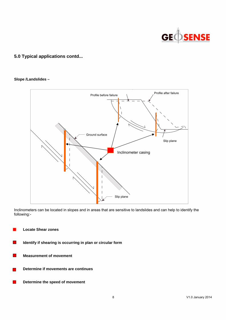
Inclinometers can be located in slopes and in areas that are sensitive to landslides and can help to identify the following:-
Slope /Landslides –
Locate Shear zones
Identify if shearing is occurring in plan or circular form
Measurement of movement
Determine if movements are continues
Determine the speed of movement
5.0 Typical applications contd...
slip plane
ground level
ground profile prior to slip ground profile
after slip
slip plane
Slip plane
Ground surface
Profile after failure
Profile before failure
Slip plane
Inclinometer casing
9 V1.0 January 2014
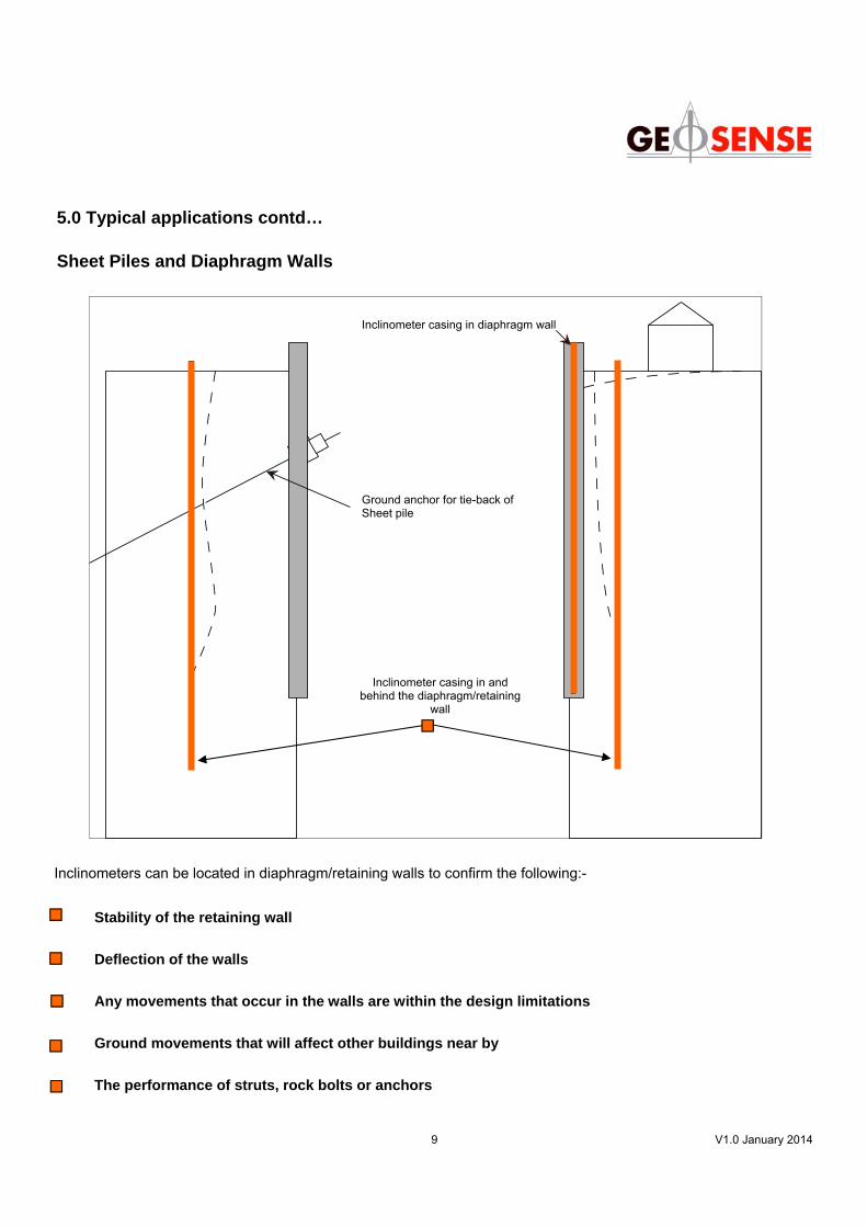
Stability of the retaining wall
Deflection of the walls
Any movements that occur in the walls are within the design limitations
Ground movements that will affect other buildings near by
The performance of struts, rock bolts or anchors
5.0 Typical applications contd… Sheet Piles and Diaphragm Walls
ground anchor
inclinometerin wall
Inclinometers can be located in diaphragm/retaining walls to confirm the following:-
Inclinometer casing in diaphragm wall
Ground anchor for tie-back of Sheet pile
Inclinometer casing in and behind the diaphragm/retaining
wall
10 V1.0 January 2014
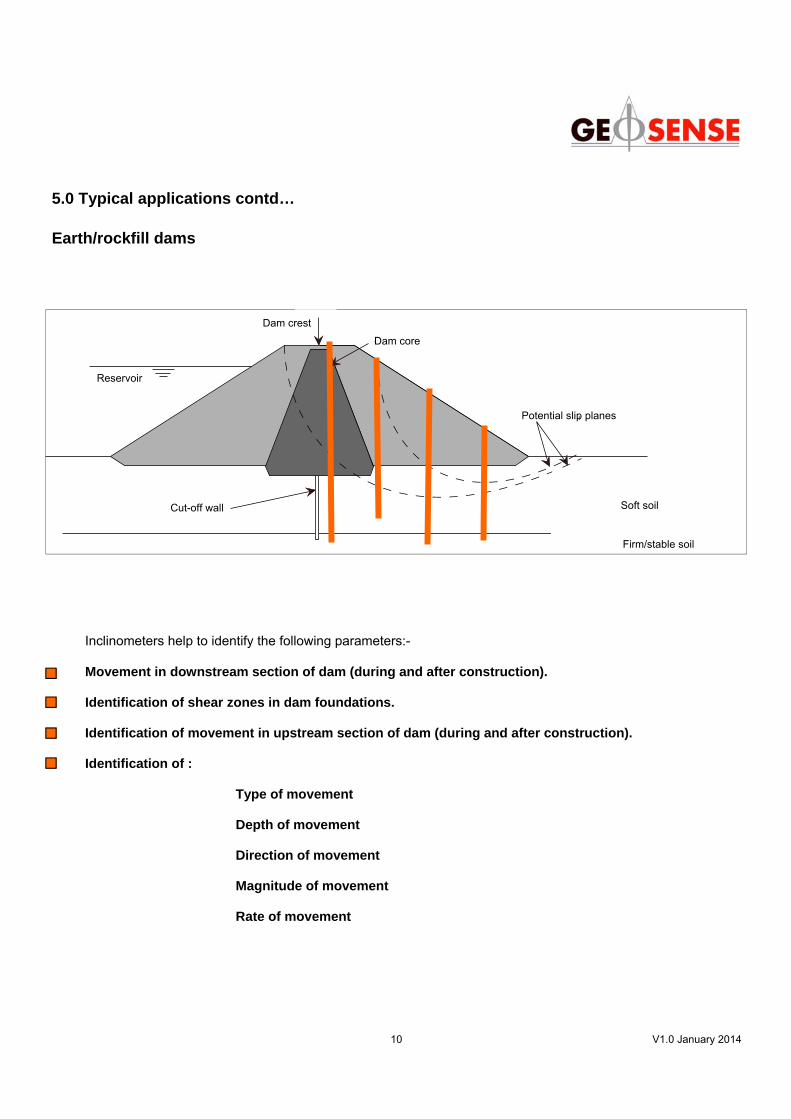
5.0 Typical applications contd… Earth/rockfill dams
Crest of Dam
Clay of Core
Firm Soil
Soft Soil
Potential Slip Planes
Resevoir
Cut-off Wall
Dam crest
Soft soil
Dam core
Reservoir
Cut-off wall
Potential slip planes
Firm/stable soil
Inclinometers help to identify the following parameters:- Movement in downstream section of dam (during and after construction).
Identification of shear zones in dam foundations.
Identification of movement in upstream section of dam (during and after construction).
Identification of :
Type of movement
Depth of movement
Direction of movement
Magnitude of movement
Rate of movement

11 V1.0 January 2014
Reservoir
Dam face & crest
Permeable Soil
Firm Soil
Cut off Wall
Inclinometer casing
5.0 Typical applications contd… Concrete faced dam
Inclinometers help to monitor and/or establish the following :- Deformation of the concrete face slab which can lead to propagation of cracks and result in seepage through the dam The stability of upstream slopes during and after filling (impounding) as failure could result in dam over-topping. Movement in the downstream side of the dam especially during filling (impounding) Whether any shear zones develop in the foundation The type, depth, direction, magnitude and rate of movement
12 V1.0 January 2014
Firm Soil
Soft Soil
Potential Slip Plane
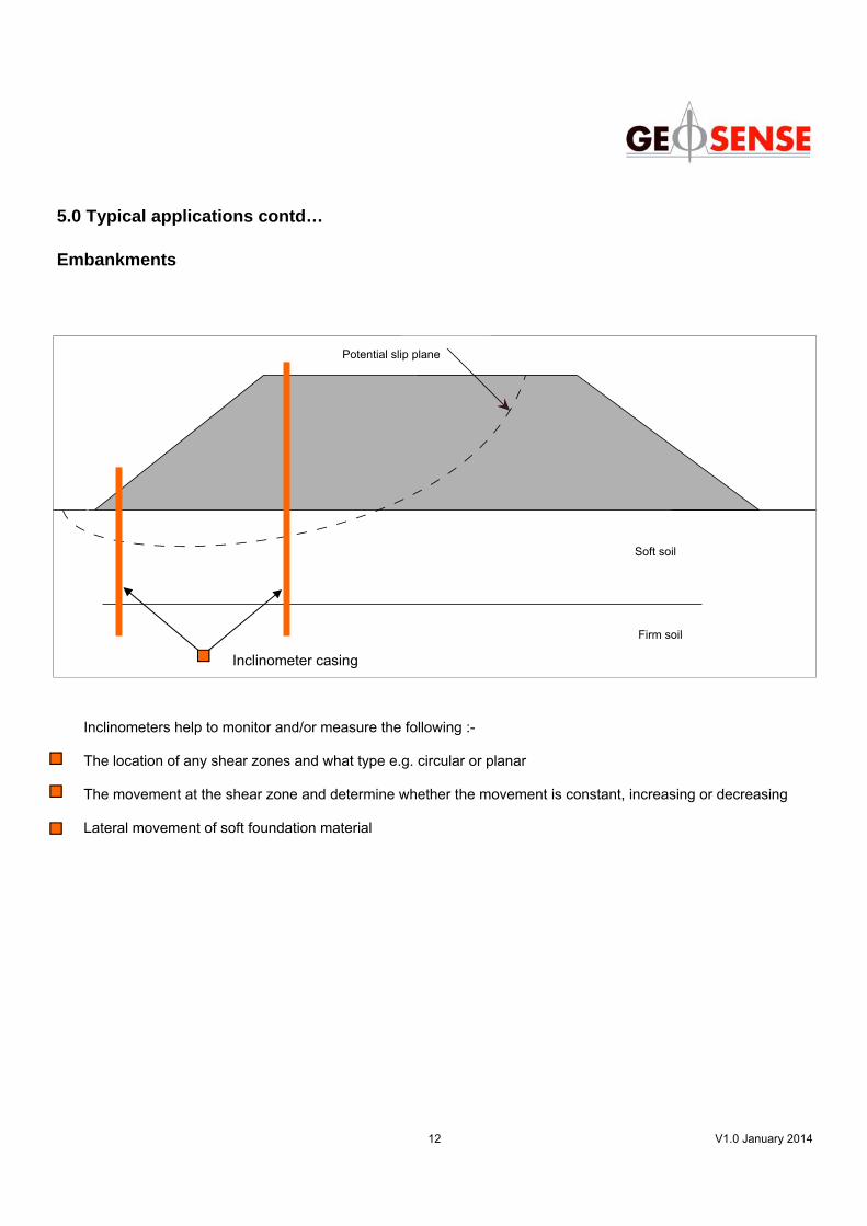
Potential slip plane
Soft soil
Firm soil
5.0 Typical applications contd… Embankments
Inclinometer casing
Inclinometers help to monitor and/or measure the following :- The location of any shear zones and what type e.g. circular or planar The movement at the shear zone and determine whether the movement is constant, increasing or decreasing Lateral movement of soft foundation material
13 V1.0 January 2014
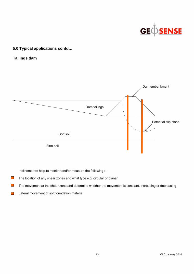
5.0 Typical applications contd… Tailings dam
Tailings
Soft Soil
Firm Soil
Dam
Potential Slip Plane
Dam tailings
Soft soil
Firm soil
Dam embankment
Potential slip plane
Inclinometers help to monitor and/or measure the following :- The location of any shear zones and what type e.g. circular or planar The movement at the shear zone and determine whether the movement is constant, increasing or decreasing Lateral movement of soft foundation material
14 V1.0 January 2014
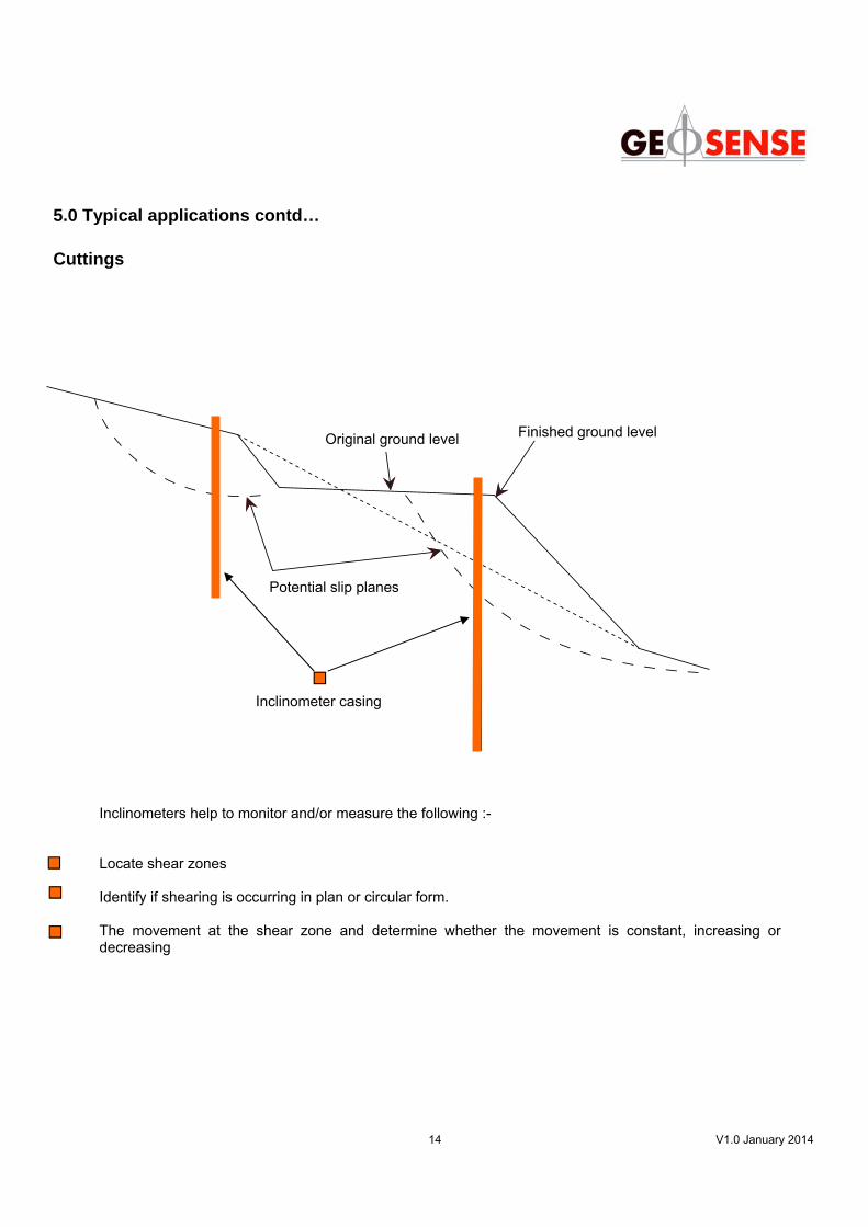
Inclinometers help to monitor and/or measure the following :- Locate shear zones Identify if shearing is occurring in plan or circular form. The movement at the shear zone and determine whether the movement is constant, increasing or decreasing
5.0 Typical applications contd… Cuttings
Potential Slip Planes
Original Ground Level Finished Ground LevelOriginal ground level Finished ground level
Potential slip planes
Inclinometer casing
15 V1.0 January 2014
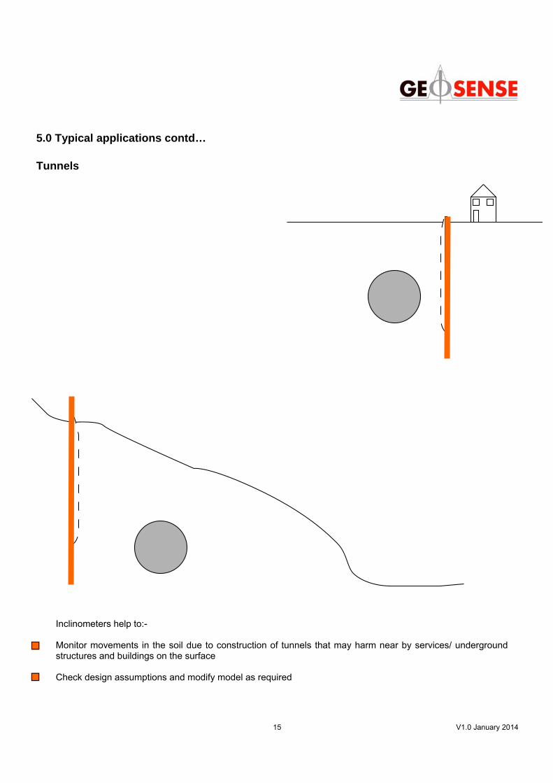
Inclinometers help to:- Monitor movements in the soil due to construction of tunnels that may harm near by services/ underground structures and buildings on the surface Check design assumptions and modify model as required
5.0 Typical applications contd… Tunnels
16 V1.0 January 2014
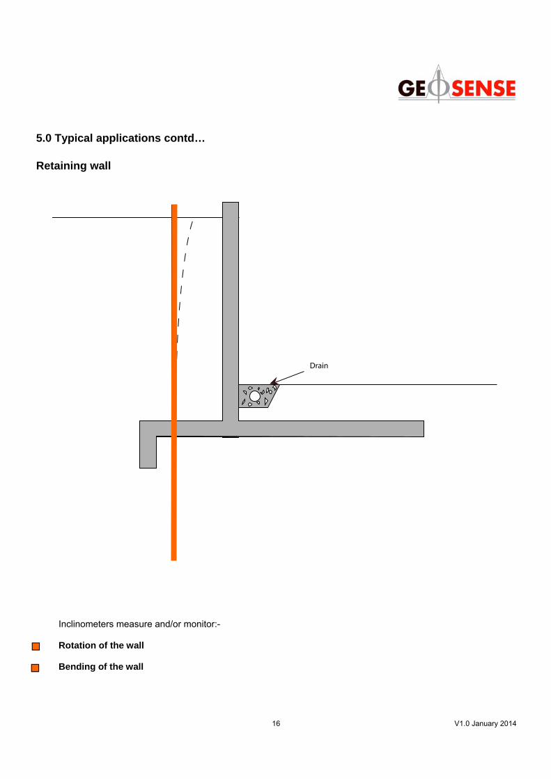
Inclinometers measure and/or monitor:- Rotation of the wall Bending of the wall
5.0 Typical applications contd… Retaining wall
Drain
17 V1.0 January 2014
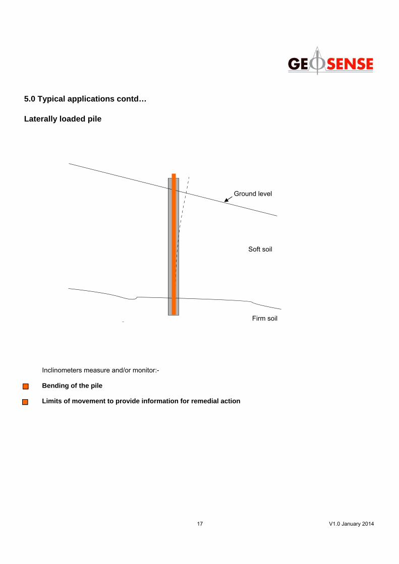
5.0 Typical applications contd… Laterally loaded pile
Inclinometers measure and/or monitor:- Bending of the pile Limits of movement to provide information for remedial action
Ground Level
Soft Soil
Firm Soil
Ground level
Soft soil
Firm soil
18 V1.0 January 2014
6.0 Purpose of inclinometer measurements Locate and measure lateral movement Lateral movement or “displacement” is the change of position of the inclinometer casing. Displacement of the inclinometer by taking away the original reading by the most resent reading taken from the inclinometer. Once a number of readings have been attained then the movement of the structure can be shown incrementally. Cumulative displacement is the addition of all the incremental data. The displacement can be seen of a inclinometer in relation to a fixed point near to the bottom of the inclinometer casing. However if the bottom of the casing is moving then the reference point of how much the inclinometer has moved can be taken from the top of the casing, that will have to be surveyed before. Locate Shear zones Inclinometers are ideal for the investigation and location of shear zones, within slopes and retaining walls for example. The accurate location, depth and type of shearing that is occurring in the affected ground that is identify by inclinometers provides information that can be used to calculate the likelihood of lateral earth movement occurring. This information provided by the inclinometer also provides information that is used to produce factors of safety for the slope. Identify if shearing is occurring in plane or circular form. The inclinometer probe also can identify what kind of shearing is occurring in a slope that can not be seen to the naked eye. The identification of the kind of shearing that is occurring e.g. plan or circular failure, will influence the calculations that need to be carried out in order to make the slope safe. Determine if movements are continuous The inclinometer probes can also identify if a slope or retaining wall is continuous. In many cases the slopes can become dormant to movement, until some environmental conditions suddenly change, due to freak weather events or the removal of vegetation and drainage. If movement starts to occur then the inclinometer probe can identify that movement is occurring and then remedial actions can then take place. Thus the inclinometer probes can be used as warning devise that is permanently in-place around sensitive areas, such as areas of high population. Determine the speed of movement. The determination of the speed of movement is key to any slope or retaining wall, this is because of the calculation of the slope stability analysis and how long it will take to reach an area of sensitivity. If need be from the speed of movement a decision can be made in the response of the speed of movement, for example if the speed of movement to fast that the a temporary sheet pile wall will need to be put in place or other remedial activates may need to be carried out, so that the speed of movement is reduced or stopped and this can only be done with measurements taken from an inclinometer probe.

19 V1.0 January 2014
7.0 Portable inclinometer measurements & plots At any position within the inclinometer casing, three readings are recorded. • Depth • Inclination ( tilt ) of the sensors in the “A” direction • Inclination ( tilt ) of the sensors in the “B” direction To minimise possible system errors, readings using portable inclinometers are each recorded twice. The probe (in which the sensors are housed ) is first read in the primary direction, “A+” then rotated through 180 degrees “A-” and the whole survey re-read. During data reduction, because there are two readings, the A- reading is subtracted from the A+ and the resultant is divided by 2. This maintains the direction of the movement , indicated by a positive or negative sign. Prior to any monitoring of a manually read inclinometer installation, a series of sets of inclinometer surveys are recorded (usually 3sets ) in a particular casing. These are called the Base Readings and usually one set is selected as the reference for all future calculations for this installation. Deviation An inclinometer sensor actually measures tilt, rather than lateral movement and therefore the basic principle requires calculations using the sine function, an angle, and the hypotenuse of a right angled triangle. This produces a value for the ‘Deviation from Vertical’. The software in the readout often carries out the conversion of the’ tilt’ to an ‘offset’ over the length of the probe, a value in mm will indicate that the top of the probe is offset from the bottom by this value; the Deviation from Vertical. The wheel centres are the ‘gauge length’ of the probe, over which the measurements are made. Displacements Displacements are calculated by comparing the current readings to the ‘Base’ or previous readings. Changes in deviation are called displacements as any change indicates that the casing has moved from its original position. When displacements are summed and plotted, the result is a high resolution representation of movement. Checksum or Face Difference A checksum or face difference is a function of the sum of an A+ reading and an A- reading at the same depth. In some cases it is divided by 2 and in other not. It serves as a ‘check’ on the quality of the data and the integrity of the inclinometer tubes. Inclinometer plots Common graphical display of inclinometer measurements include: 1. Cumulative displacement - a plot of cumulative displacement at depth against time. Starting, normally, at the base of the installation, the displacements at each elevation are added together to create an accumulative plot of displacements at each elevation from the base upwards. Sequential data sets generate a new plot line. 2. Incremental displacement - a plot of incremental displacement at depth at each depth. Sequential data sets generate a new plot line. 4. Cumulative deviation – a plot showing the profile of the casing relative to vertical (cumulative deviation against depth). Since inclination of the casing can contribute to error, the cumulative deviation plot is useful for diagnosing and correcting “rotational” errors. 5. Incremental deviation - a plot of the readings converted to lateral offset at each reading interval (incremental deviation against depth).

20 V1.0 January 2014
7.0 Inclinometer measurements & plots contd... 6. Checksum - shows checksums for each data set and can be used to evaluate the quality of the datasets. Spikes in the plot may indicate bad readings or a characteristic of the casing. 7. Polar cumulative displacement – shows the cumulative displacement of the casing movement assuming the top or bottom of the casing as reference and as origin of the movements This is the change in position of the tube looking along tis length. 8. Polar cumulative deviation - shows the cumulative deviation of the casing assuming the top or bottom of the casing as reference and as origin of the measurements. This is the actual ‘shape’ of the installed tube looking along its length. Inclinometer bias - the difference between a probe’s non-zero value at true verticality is known as the probe’s bias. Every inclinometer probe has a very small bias, which can change through the life of the probe. Bias shifts are not normally a matter for concern because the value of the bias is effectively eliminated by the standard two-pass survey and data reduction procedure.

21 V1.0 January 2014
8.0 Operation 8.1 Good practice When conducting inclinometer surveys there are a number of good working measures that includes:- ● The use of the same probe and cable - this provides the most accurate survey. ● When conducting an inclinometer survey it is important to mark the direction or groove of the first readings
that are to be taken. ● When taking the first readings after installation, it is good practice to take at least 3 initial readings first, so
that reliable data can be obtained from the inclinometer casing. ● Use the same reference point, either the bottom or top of the casing. ● Using a cable gate at the top provides a more repeatable point and helps protect the cable from damage. ● Ensure the probe is adequately protected for storage and transportation. 8.2 Instrument preparation and handling ● Ensure that probe wheels and carriages are moving smoothly. If necessary spray with suitable lubricant ● Inspect O-rings and connectors for wear and damage. NEVER USE AN OIL BASED LUBRICANT ON THE CABLE TO PROBE CONNECTOR AS THIS WILL DAMAGE IT ● Ensure the cable reel and readout have fully charged batteries. ● Attach probe to cable, ensuring the connection is hand tight (do not over tighten) ● Connect PDA to probe and cable reel via Bluetooth. 8.3 An inclinometer survey ● Identify the A+ groove in the casing. Insert the probe so that the lowermost wheel is in the opposite groove
(A-) and the uppermost wheel is in the A+ groove. ● Lower probe to base of casing and where necessary allow the probe temperature to stabilise. ● Using the cable gate to support the cable, raise the probe through 500mm intervals, allowing the readings
to stabilise at each interval and then record them on the readout. ● Once the probe reaches the top of the casing, remove it, rotate it 180º and reinsert into the casing so that
the lowest wheel is in the A+ groove. Lower to base of casing and complete survey. ● If a point or measurement is missed lower the inclinometer probe to one point below the missed recording
point and pull up to the missed point again and record the reading. 8.4 Taking readings - please refer to Operators Manual 8.5 Data handling - data can either be manipulated manually or by specialist software packages such as Inclinalysis - for full details please refer to the Data Handling section or the manual

22 V1.0 January 2014
Geosense Ltd
Nova House . Rougham Industrial Estate . Rougham . Bury St Edmunds . Suffolk . IP30 9ND . England .
Tel: +44 (0) 1359 270457 . Fax: +44 (0) 1359 272860 . email: [email protected] . www.geosense.co.uk