APL - Advanced Production and Loading AS BTL™ - Buoy ...1).pdf · 44 Company APL - Advanced...
4
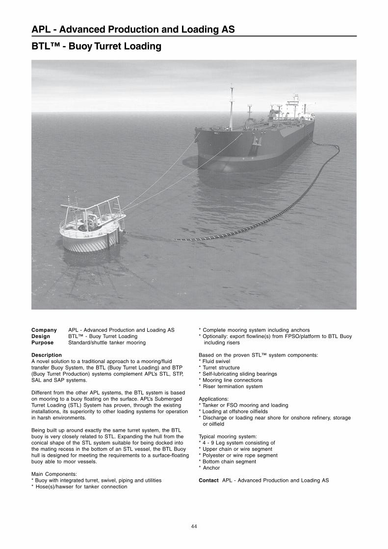
44 Company APL - Advanced Production and Loading AS Design BTL™ - Buoy Turret Loading Purpose Standard/shuttle tanker mooring Description A novel solution to a traditional approach to a mooring/fluid transfer Buoy System, the BTL (Buoy Turret Loading) and BTP (Buoy Turret Production) systems complement APL’s STL, STP, SAL and SAP systems. Different from the other APL systems, the BTL system is based on mooring to a buoy floating on the surface. APL’s Submerged Turret Loading (STL) System has proven, through the existing installations, its superiority to other loading systems for operation in harsh environments. Being built up around exactly the same turret system, the BTL buoy is very closely related to STL. Expanding the hull from the conical shape of the STL system suitable for being docked into the mating recess in the bottom of an STL vessel, the BTL Buoy hull is designed for meeting the requirements to a surface-floating buoy able to moor vessels. Main Components: * Buoy with integrated turret, swivel, piping and utilities * Hose(s)/hawser for tanker connection * Complete mooring system including anchors * Optionally: export flowline(s) from FPSO/platform to BTL Buoy including risers Based on the proven STL™ system components: * Fluid swivel * Turret structure * Self-lubricating sliding bearings * Mooring line connections * Riser termination system Applications: * Tanker or FSO mooring and loading * Loading at offshore oilfields * Discharge or loading near shore for onshore refinery, storage or oilfield Typical mooring system: * 4 - 9 Leg system consisting of * Upper chain or wire segment * Polyester or wire rope segment * Bottom chain segment * Anchor Contact APL - Advanced Production and Loading AS APL - Advanced Production and Loading AS BTL™ - Buoy Turret Loading
Transcript of APL - Advanced Production and Loading AS BTL™ - Buoy ...1).pdf · 44 Company APL - Advanced...
44
Company APL - Advanced Production and Loading ASDesign BTL™ - Buoy Turret LoadingPurpose Standard/shuttle tanker mooring
DescriptionA novel solution to a traditional approach to a mooring/fluidtransfer Buoy System, the BTL (Buoy Turret Loading) and BTP(Buoy Turret Production) systems complement APL’s STL, STP,SAL and SAP systems.
Different from the other APL systems, the BTL system is basedon mooring to a buoy floating on the surface. APL’s SubmergedTurret Loading (STL) System has proven, through the existinginstallations, its superiority to other loading systems for operationin harsh environments.
Being built up around exactly the same turret system, the BTLbuoy is very closely related to STL. Expanding the hull from theconical shape of the STL system suitable for being docked intothe mating recess in the bottom of an STL vessel, the BTL Buoyhull is designed for meeting the requirements to a surface-floatingbuoy able to moor vessels.
Main Components:* Buoy with integrated turret, swivel, piping and utilities* Hose(s)/hawser for tanker connection
* Complete mooring system including anchors* Optionally: export flowline(s) from FPSO/platform to BTL Buoy including risers
Based on the proven STL™ system components:* Fluid swivel* Turret structure* Self-lubricating sliding bearings* Mooring line connections* Riser termination system
Applications:* Tanker or FSO mooring and loading* Loading at offshore oilfields* Discharge or loading near shore for onshore refinery, storage or oilfield
Typical mooring system:* 4 - 9 Leg system consisting of* Upper chain or wire segment* Polyester or wire rope segment* Bottom chain segment* Anchor
Contact APL - Advanced Production and Loading AS
APL - Advanced Production and Loading AS
BTL™ - Buoy Turret Loading
274
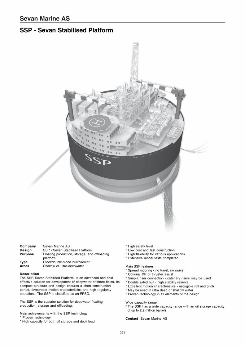
Company Sevan Marine ASDesign SSP - Sevan Stabilised PlatformPurpose Floating production, storage, and offloading
platformType Steel/double-sided hull/circularAreas Shallow or ultra-deepwater
DescriptionThe SSP, Sevan Stabilized Platform, is an advanced and cost-effective solution for development of deepwater offshore fields. Itscompact structure and design ensures a short constructionperiod, favourable motion characteristics and high regularityoperations. The SSP is classified as an FPSO.
The SSP is the superior solution for deepwater floatingproduction, storage and offloading.
Main achievements with the SSP technology:* Proven technology* High capacity for both oil storage and deck load
Sevan Marine AS
SSP - Sevan Stabilised Platform
* High safety level* Low cost and fast construction* High flexibility for various applications* Extensive model tests completed
Main SSP features:* Spread mooring - no turret, no swivel* Optional DP or thruster assist* Simple riser connection - catenary risers may be used* Double sided hull - high stability reserve* Excellent motion characteristics - negligible roll and pitch* May be used in ultra deep or shallow water* Proven technology in all elements of the design
Wide capacity range:* The SSP has a wide capacity range with an oil storage capacity of up to 2.2 million barrels
Contact Sevan Marine AS
65
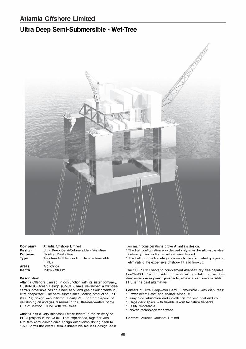
Company Atlantia Offshore LimitedDesign Ultra Deep Semi-Submersible - Wet-TreePurpose Floating ProductionType Wet-Tree Full Production Semi-submersible
(FPU)Areas WorldwideDepth 150m - 3000m
DescriptionAtlantia Offshore Limited, in conjunction with its sister company,GustoMSC-Ocean Design (GMOD), have developed a wet-treesemi-submersible design aimed at oil and gas developments inultra deepwater. The semi-submersible floating production unit(SSFPU) design was initiated in early 2003 for the purpose ofdeveloping oil and gas reserves in the ultra-deepwaters of theGulf of Mexico (GOM) with wet trees.
Atlantia has a very successful track-record in the delivery ofEPCI projects in the GOM. That experience, together withGMOD’s semi-submersible design experience dating back to1977, forms the overall semi-submersible facilities design team.
Atlantia Offshore Limited
Ultra Deep Semi-Submersible - Wet-Tree
Two main considerations drove Atlantia’s design.* The hull configuration was derived only after the allowable steel catenary riser motion envelope was defined.* The hull to topsides integration was to be completed quay-side, eliminating the expensive offshore lift and hookup.
The SSFPU will serve to complement Atlantia’s dry tree capableSeaStar® TLP and provide our clients with a solution for wet treedeepwater development prospects, where a semi-submersibleFPU is the best alternative.
Benefits of Ultra Deepwater Semi Submersible - with Wet-Trees:* Lower overall cost and shorter schedule* Quay-side fabrication and installation reduces cost and risk* Large deck space with flexible layout for future tiebacks* Easily relocatable* Proven technology worldwide
Contact Atlantia Offshore Limited

69
Company Bennett & Associates LLCDesign B-SEMI - Deepwater Semi-submersible Drilling
UnitPurpose Deepwater exploration and development drillingType Square semi-submersibleAreas Deepwater GOM, West Africa, Brazil
DescriptionB-SEMI is a semi-submersible drilling unit that was developed forthe exploration and development of the deep-water reservoirs.This design was conceived to provide the industry with aneconomical MODU that is capable of being operated in themoored condition in 1525 to 2440m (5000 to 8000ft) of water.Alternatively it can be outfitted with thrusters and a dynamicpositioning system to operate without the spread mooring. Thisparticular version of this design is not intended for operations inthe most severe environments, such as the Northern North Seaor West of the Shetlands. It was designed for operations in thedeepwater Gulf of Mexico, West Africa, Brazil and other similarenvironments. The name B-SEMI was chosen to provide a link toits designers, Bennett & Associates and to describe its relativelyboxy form.
The shape of the B-SEMI is square, which, other than thetriangle, is one of the most stable types of structural elementsthat can be utilised in a design. This shape also provides for aclean and efficient drilling unit. The box hull form is stable to towand maintain course stability when it is towed with one columninto the seas. It has been designed to have respectable motionswithout having to complicate the structure to obtain better heavecharacteristics. The areas of operation for ultra deep drilling unitsare relatively benign with the exception of those sights west ofthe Shetlands. The decision was made not to penalise the rest ofthe deepwater locations by over-designing this unit for theShetlands environmental conditions; instead it was specificallydesigned for the Gulf of Mexico and West Coast of Africa.
B-SEMI consists of several rectangular sections, which aredesigned for ease of fabrication and have been assembled toachieve the most efficient utilisation of the structure and to permitease of erection. The lower hull is made up of three pontoonsthat form a triangular ring at the base of the columns. They are inturn attached to form a square lower hull. Four square outercolumns extend upwards from the lower hulls to support the
upper hull and provide the stability of the unit. The upper hull isalso of rectangular shape and supports the unit’s equipment,quarters and the mooring system.
The displacement of the B-SEMI is only slightly greater than thatof an Enhanced Pacesetter, yet it can support a variable deckload of 6000 tons. Additionally, its eight-point mooring system caneasily provide stationkeeping characteristics for a rectangularunit of this size. The hull and columns are arranged to permitclean egress of the mooring lines so the chains or wires will notbe chafed even at the most critical mooring line angles. Thestorage of the risers on either side of the upper hull providesample storage area for even the most aggressive casingprograms. Riser joints of just about any length can beaccommodated due to the configuration of the cranes and decks.The knuckle-boom cranes can handle the riser from theoperator’s cab and feed it to the drillfloor without the need fordouble handling or other special apparatus.
The B-SEMI is designed to operate at a single draft for bothsurvival and operations thereby eliminating some of the operatingcomplexities and stability considerations. In areas having milderenvironmental conditions, deeper drafts may be desirable forimproved motion criteria resulting in having both an operationaland survival draft.
Dimensions:Length overall (excluding anchor racks and helideck) 62.00mBreadth overall (excluding anchor and riser racks) 62.00mHeight, baseline to main deck 36.00m
Lower hull: Square hulls: Breadth 16.00m Depth 8.00mColumns: Outer columns (4): Breadth 16.00m Length 16.00mSpacing CL to CL 22.00m
Upper hull: Length overall: 62.00m Breadth overall: 48.00mHeight to column tops: 28.50m Height to main deck:36.60mHeight to drillfloor: 40.50mDepth: 8.10m
Certification: Classification Society - American Bureau of ShippingA1 M Column Stabilized Drilling UnitConventions - IMO MODU Code 1989- SOLAS 1974 (Including Amendments)- MARPOL 73/78 (Including Amendments)
Operating conditions: Transit Storm DrillingDraft 11m 18m 18mDisplacement 27,256t 34,582t 34,582tVariable deck load 4,500t 6,000t 6,000t
Drillfloor and substructure: Dynamic derrick rated 1500 kipSetback 600 kip under towCrown compensator: Active 600 kip Locked 750 kipTop Drive TDS 4-S 750stCombination iron roughneck/racking systemDrawworks 3000hpHydraulic rotary 60inSubstructure 3000 kip
Mud System:Liquid mud Active main deck 4200bblReserve columns 5500bblBrine tanks 8000bblBase oil 4000bblBulk materials:Cement & Mud 20,000ft³Sack Storage 8000 sacksMud pumps 3 x 7500psi
Lightship 17,820tSteel weight 10,500t
Contact Bennett & Associates LLC
Bennett & Associates LLC
B-SEMI