
- USER MANUAL - Underwater pop-up buoy,ropeless buoy ...
68
FIOBUOY is a registered trade mark of Fiomarine Investments Pty Limited. Copyright 1997-2016 Fiomarine Investments Pty Limited. All rights reserved. - USER MANUAL – Acoustic Model Fiobuoy ® and Deck Interface Unit (Revision Jan 2016) INDUSTRIES PTY LIMITED ACN 074 357 869 ABN 91 442 031 533
Transcript of - USER MANUAL - Underwater pop-up buoy,ropeless buoy ...
FIOBUOY is a registered trade mark of Fiomarine Investments Pty Limited.
Copyright 1997-2016 Fiomarine Investments Pty Limited. All rights reserved.
- USER MANUAL –
Acoustic Model Fiobuoy®
and Deck Interface Unit
(Revision Jan 2016)
INDUSTRIES PTY LIMITEDACN 074 357 869
ABN 91 442 031 533

If you only ever read
one part of this manual,
read
Section 24-
‘ AVOIDING PROBLEMS - A LAST WORD ’

Contents
1. FIOBUOY® RETRIEVAL SYSTEM - OVERVIEW ................................................ 1
2. COMMUNICATIONS CONCEPT - OVERVIEW .................................................. 2
The Acoustic Fiobuoy®
3. DESCRIPTION OF PRINCIPAL COMPONENTS ................................................ 7
4. INFRA-RED COMMUNICATION CABLE ............................................................. 9
5. PRE-DEPLOYMENT SETUP OF THE FIOUBOY ............................................ 12
MENU OPTION 1 – PROGRAM/CHECK RELEASE EVENT .................................. 14
MENU OPTION 2 – SET BUOY CLOCK ........................................................... 18
MENU OPTION 3 – TEST JAWS ..................................................................... 19
MENU OPTION 4 – EXIT ................................................................................ 19
MENU OPTION 5 – SET STORAGE MODE ....................................................... 21
MENU OPTION 0 – THIS SCREEN .................................................................. 22
6. DEPLOYMENT ................................................................................................... 23
7. RETRIEVAL ....................................................................................................... 24
8. BENCH TESTING A ‘TIMED’ RELEASE EVENT .............................................. 25
9. STROBE LIGHT OPTION .................................................................................. 27
10. ERROR CODES ................................................................................................. 29
11. BATTERY LIFE .................................................................................................. 31
ADJUSTING FIOBUOY ACOUSTIC LISTENING BAND’ ............................................ 32
12. MAINTENANCE ................................................................................................. 33
EXTERNAL MAINTENANCE ................................................................................ 34
INSTALLING TETHER LINE ......................................................................... 35
INTERNAL MAINTENANCE ................................................................................. 36
13. BATTERY-PACK REPLACEMENT .................................................................... 37
RELEASE END-CAP MAINTENANCE. .................................................................. 40
INSPECTION AND SERVICE ................................................................................ 43
ASSEMBLE AND TEST ....................................................................................... 44
14. HIDDEN MENU OPTIONS ................................................................................. 45
15. PRODUCT SPECIFICATIONS (FIOBUOY®) ..................................................... 47
The Deck Interface Unit (DIU)
16. OPERATING PROCEDURES ............................................................................ 50
OVERVIEW: ..................................................................................................... 50
MENU OPTION 1 – SELECT A FIOBUOY.......................................................... 52
MENU OPTION 2 – WAKE THE FIOBUOY ........................................................ 52
MENU OPTION 3 – CHECK FIOBUOY BATTERY. .............................................. 53
MENU OPTION 4 – ACTIVATE RELEASE NOW. ............................................... 54
17. MAINTENANCE ................................................................................................. 55
18. BENCH TESTING – ACOUSTIC COMMUNICATIONS. .................................... 56
19. ABOUT THROUGH-WATER ACOUSTIC COMMUNICATIONS ....................... 58
20. PRODUCT SPECIFICATIONS (DECK INTERFACE UNIT) .............................. 60
General
21. PARTS LIST ....................................................................................................... 62
22. WARRANTY ....................................................................................................... 63
23. AVOIDING PROBLEMS - A LAST WORD ........................................................ 64
24. CONTACTING US ............................................................................................. 65
USER MANUAL Acoustic Fiobuoy Model SAC 1.8
Page 1 rev: Jan2016
1. Fiobuoy® Retrieval System - Overview
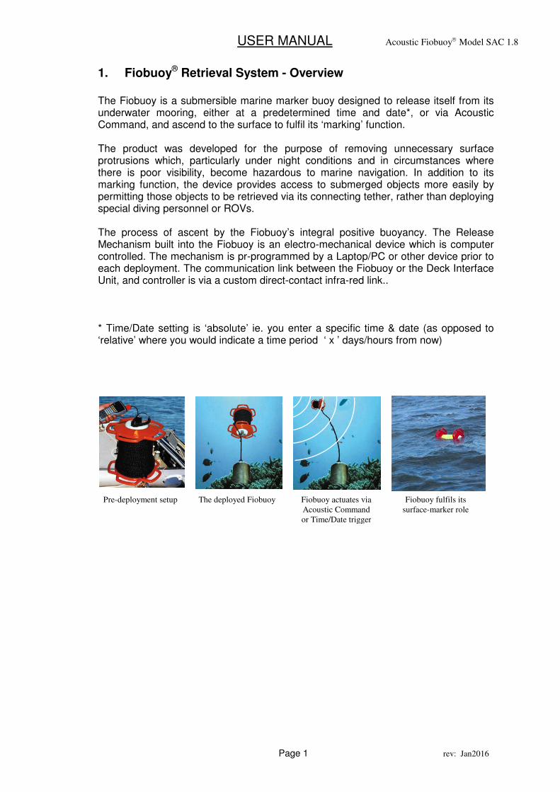
The Fiobuoy is a submersible marine marker buoy designed to release itself from its underwater mooring, either at a predetermined time and date*, or via Acoustic Command, and ascend to the surface to fulfil its ‘marking’ function. The product was developed for the purpose of removing unnecessary surface protrusions which, particularly under night conditions and in circumstances where there is poor visibility, become hazardous to marine navigation. In addition to its marking function, the device provides access to submerged objects more easily by permitting those objects to be retrieved via its connecting tether, rather than deploying special diving personnel or ROVs. The process of ascent by the Fiobuoy’s integral positive buoyancy. The Release Mechanism built into the Fiobuoy is an electro-mechanical device which is computer controlled. The mechanism is pr-programmed by a Laptop/PC or other device prior to each deployment. The communication link between the Fiobuoy or the Deck Interface Unit, and controller is via a custom direct-contact infra-red link.. * Time/Date setting is ‘absolute’ ie. you enter a specific time & date (as opposed to ‘relative’ where you would indicate a time period ‘ x ’ days/hours from now)
Pre-deployment setup The deployed Fiobuoy Fiobuoy actuates via
Acoustic Command
or Time/Date trigger
Fiobuoy fulfils its
surface-marker role
USER MANUAL Acoustic Fiobuoy Model SAC 1.8
Page 2 rev: Jan2016
2. COMMUNICATIONS CONCEPT - Overview
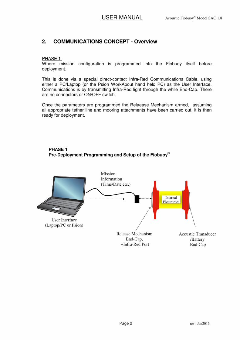
PHASE 1 Where mission configuration is programmed into the Fiobuoy itself before deployment. This is done via a special direct-contact Infra-Red Communications Cable, using either a PC/Laptop (or the Psion WorkAbout hand held PC) as the User Interface. Communications is by transmitting Infra-Red light through the while End-Cap. There are no connectors or ON/OFF switch. Once the parameters are programmed the Relaease Mechanism armed, assuming all appropriate tether line and mooring attachments have been carried out, it is then ready for deployment.
User Interface
(Laptop/PC or Psion)
Mission
Information
(Time/Date etc.)
PHASE 1 Pre-Deployment Programming and Setup of the Fiobuoy
®
Acoustic Transducer
/Battery
End-Cap
Release Mechanism
End-Cap,
+Infra-Red Port
Internal
Electronics
USER MANUAL Acoustic Fiobuoy Model SAC 1.8
Page 3 rev: Jan2016
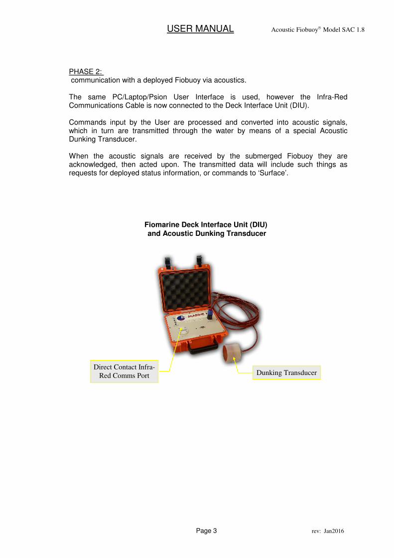
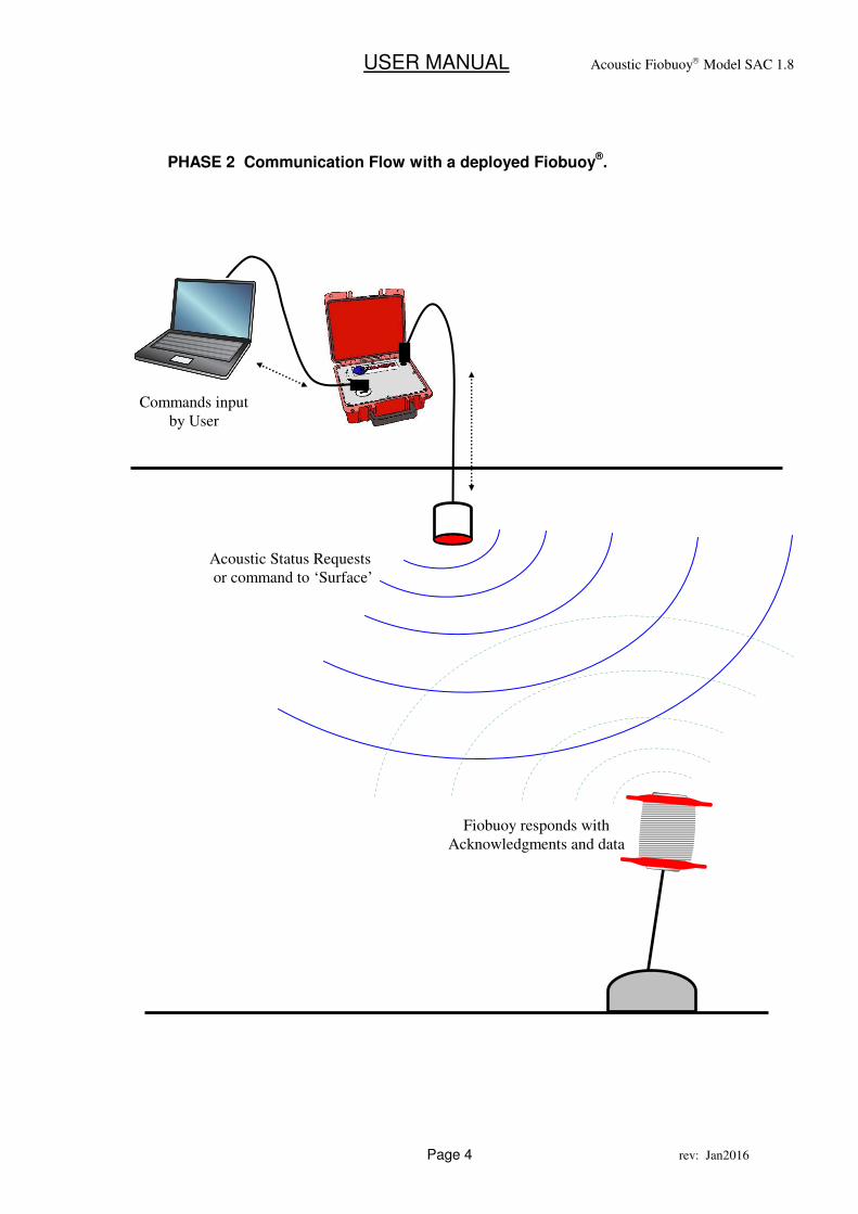
PHASE 2: communication with a deployed Fiobuoy via acoustics. The same PC/Laptop/Psion User Interface is used, however the Infra-Red Communications Cable is now connected to the Deck Interface Unit (DIU). Commands input by the User are processed and converted into acoustic signals, which in turn are transmitted through the water by means of a special Acoustic Dunking Transducer. When the acoustic signals are received by the submerged Fiobuoy they are acknowledged, then acted upon. The transmitted data will include such things as requests for deployed status information, or commands to ‘Surface’.
Fiomarine Deck Interface Unit (DIU) and Acoustic Dunking Transducer
Dunking Transducer Direct Contact Infra-
Red Comms Port
USER MANUAL Acoustic Fiobuoy Model SAC 1.8
Page 4 rev: Jan2016
Acoustic Status Requests
or command to ‘Surface’
PHASE 2 Communication Flow with a deployed Fiobuoy®.
Commands input
by User
Fiobuoy responds with
Acknowledgments and data

USER MANUAL Acoustic Fiobuoy Model SAC 1.8
Page 5 rev: Jan2016
USER MANUAL Acoustic Fiobuoy Model SAC 1.8
Page 6 rev: Jan2016
The Acoustic Fiobuoy®
USER MANUAL Acoustic Fiobuoy Model SAC 1.8
Page 7 rev: Jan2016
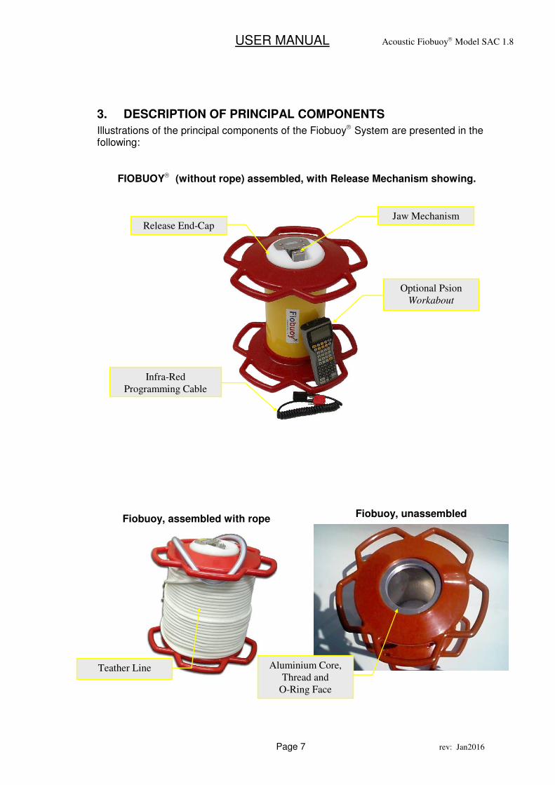
3. DESCRIPTION OF PRINCIPAL COMPONENTS
Illustrations of the principal components of the Fiobuoy System are presented in the following:
FIOBUOY (without rope) assembled, with Release Mechanism showing.
Fiobuoy, assembled with rope Fiobuoy, unassembled
Jaw Mechanism
Optional Psion
Workabout
Infra-Red
Programming Cable
Release End-Cap
Aluminium Core,
Thread and
O-Ring Face
Teather Line
USER MANUAL Acoustic Fiobuoy Model SAC 1.8
Page 8 rev: Jan2016
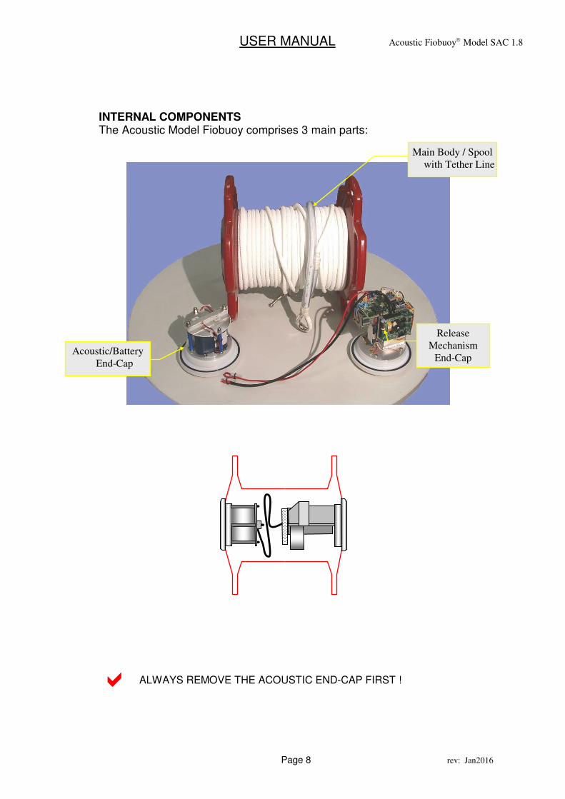
INTERNAL COMPONENTS The Acoustic Model Fiobuoy comprises 3 main parts:
ALWAYS REMOVE THE ACOUSTIC END-CAP FIRST !
Acoustic/Battery
End-Cap
Release
Mechanism
End-Cap
Main Body / Spool
with Tether Line
�
USER MANUAL Acoustic Fiobuoy Model SAC 1.8
Page 9 rev: Jan2016
4. INFRA-RED COMMUNICATION CABLE
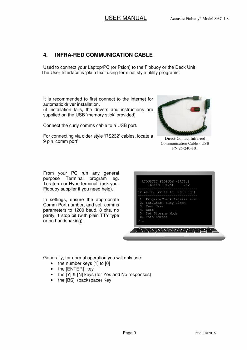
Used to connect your Laptop/PC (or Psion) to the Fiobuoy or the Deck Unit
The User Interface is ‘plain text’ using terminal style utility programs. It is recommended to first connect to the internet for automatic driver installation. (if installation fails, the drivers and instructions are supplied on the USB ‘memory stick’ provided) Connect the curly comms cable to a USB port. For connecting via older style ‘RS232’ cables, locate a 9 pin ‘comm port’ From your PC run any general purpose Terminal program eg. Teraterm or Hyperterminal. (ask your Fiobuoy supplier if you need help). In settings, ensure the appropriate Comm Port number, and set comms parameters to 1200 baud, 8 bits, no parity, 1 stop bit (with plain TTY type or no handshaking). Generally, for normal operation you will only use:
• the number keys [1] to [0]
• the [ENTER] key
• the [Y] & [N] keys (for Yes and No responses)
• the [BS] (backspace) Key
ACOUSTIC FIOBUOY -SAC1.8 (build 09X25) 7.6V ------------------------------ 12:48:35 22-10-16 (000 000) ------------------------------ 1. Program/Check Release event 2. Set/Check Buoy Clock 3. Test Jaws 4. Exit 5. Set Storage Mode 0. This Screen > _
Direct-Contact Infra-red
Communication Cable - USB
PN 25-240-101
USER MANUAL Acoustic Fiobuoy Model SAC 1.8
Page 10 rev: Jan2016
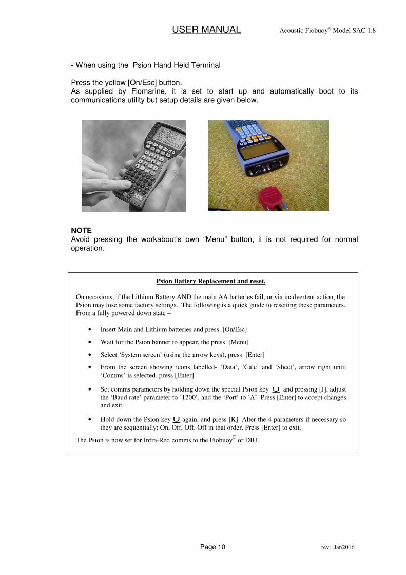
- When using the Psion Hand Held Terminal Press the yellow [On/Esc] button. As supplied by Fiomarine, it is set to start up and automatically boot to its communications utility but setup details are given below.
NOTE Avoid pressing the workabout’s own “Menu” button, it is not required for normal operation.
Psion Battery Replacement and reset.
On occasions, if the Lithium Battery AND the main AA batteries fail, or via inadvertent action, the
Psion may lose some factory settings. The following is a quick guide to resetting these parameters.
From a fully powered down state –
• Insert Main and Lithium batteries and press [On/Esc]
• Wait for the Psion banner to appear, the press [Menu]
• Select ‘System screen’ (using the arrow keys), press [Enter]
• From the screen showing icons labelled- ‘Data’, ‘Calc’ and ‘Sheet’, arrow right until
‘Comms’ is selected, press [Enter].
• Set comms parameters by holding down the special Psion key u and pressing [J], adjust
the ‘Baud rate’ parameter to ‘1200’, and the ‘Port’ to ‘A’. Press [Enter] to accept changes
and exit.
• Hold down the Psion key u again, and press [K]. Alter the 4 parameters if necessary so
they are sequentially: On, Off, Off, Off in that order. Press [Enter] to exit.
The Psion is now set for Infra-Red comms to the Fiobuoy®
or DIU.
USER MANUAL Acoustic Fiobuoy Model SAC 1.8
Page 11 rev: Jan2016
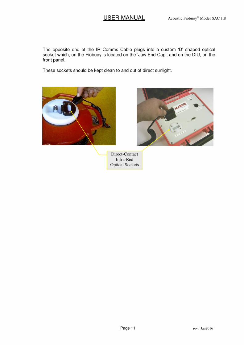
The opposite end of the IR Comms Cable plugs into a custom ‘D’ shaped optical socket which, on the Fiobuoy is located on the ‘Jaw End-Cap’, and on the DIU, on the front panel. These sockets should be kept clean to and out of direct sunlight.
Direct-Contact
Infra-Red
Optical Sockets
USER MANUAL Acoustic Fiobuoy Model SAC 1.8
Page 12 rev: Jan2016
5. PRE-DEPLOYMENT SETUP OF THE FIOUBOY
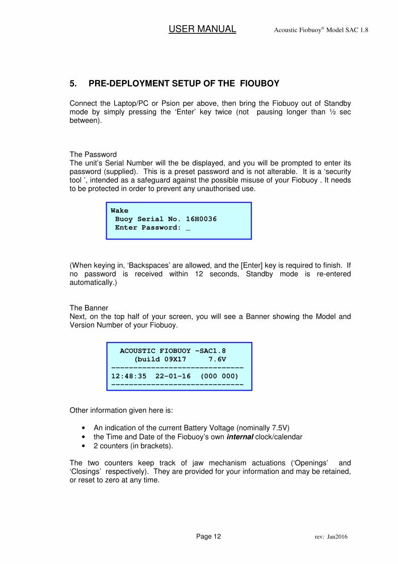
Connect the Laptop/PC or Psion per above, then bring the Fiobuoy out of Standby mode by simply pressing the ‘Enter’ key twice (not pausing longer than ½ sec between). The Password The unit’s Serial Number will the be displayed, and you will be prompted to enter its password (supplied). This is a preset password and is not alterable. It is a ‘security tool ’, intended as a safeguard against the possible misuse of your Fiobuoy . It needs to be protected in order to prevent any unauthorised use. (When keying in, ‘Backspaces’ are allowed, and the [Enter] key is required to finish. If no password is received within 12 seconds, Standby mode is re-entered automatically.) The Banner Next, on the top half of your screen, you will see a Banner showing the Model and Version Number of your Fiobuoy. Other information given here is:
• An indication of the current Battery Voltage (nominally 7.5V)
• the Time and Date of the Fiobuoy’s own internal clock/calendar
• 2 counters (in brackets). The two counters keep track of jaw mechanism actuations (‘Openings’ and ‘Closings’ respectively). They are provided for your information and may be retained, or reset to zero at any time.
Wake
Buoy Serial No. 16H0036
Enter Password: _
ACOUSTIC FIOBUOY –SAC1.8
(build 09X17 7.6V
------------------------------
12:48:35 22-01-16 (000 000)
------------------------------
USER MANUAL Acoustic Fiobuoy Model SAC 1.8
Page 13 rev: Jan2016
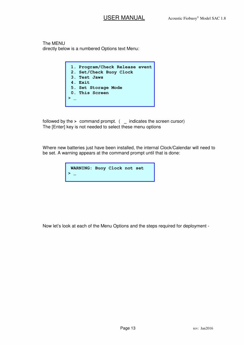
The MENU directly below is a numbered Options text Menu:
followed by the > command prompt. ( _ indicates the screen cursor)
The [Enter] key is not needed to select these menu options Where new batteries just have been installed, the internal Clock/Calendar will need to be set. A warning appears at the command prompt until that is done: Now let’s look at each of the Menu Options and the steps required for deployment -
1. Program/Check Release event
2. Set/Check Buoy Clock
3. Test Jaws
4. Exit
5. Set Storage Mode
0. This Screen
> _
WARNING: Buoy Clock not set
> _
USER MANUAL Acoustic Fiobuoy Model SAC 1.8
Page 14 rev: Jan2016
MENU OPTION 1 – Program/Check Release event
Used to program in some future Time & Date when the Fiobuoy will activate and come to the surface. Set it be some time after the intended retrieval via Acoustic Command
It is strongly recommended to use this designed backup feature as a failsafe. Regardless, this step is required to close (arm) the Jaw so that it will accept the Release Pin for deployment. In this way. NOTES
• Warning: There is no automatic return to sleep mode ‘during’ any of these
programming stages so ensure you fully complete each stage.
• None of the time or date information is held or saved on your PC/Laptop (or inside the
Psion workabout). It is retained inside the Fiobuoy only
• If required it is possible disable the Date/Time backup by setting them in the past, but
this is not advised.
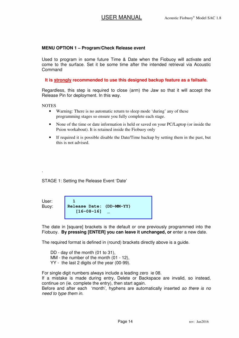
. STAGE 1: Setting the Release Event ‘Date’ User: Buoy: The date in [square] brackets is the default or one previously programmed into the Fiobuoy. By pressing [ENTER] you can leave it unchanged, or enter a new date. The required format is defined in (round) brackets directly above is a guide.
DD - day of the month (01 to 31), MM - the number of the month (01 - 12), YY - the last 2 digits of the year (00-99).
For single digit numbers always include a leading zero ie 08. If a mistake is made during entry, Delete or Backspace are invalid, so instead, continue on (ie. complete the entry), then start again. Before and after each ‘month’, hyphens are automatically inserted so there is no need to type them in.
1
Release Date: (DD-MM-YY)
[16-08-16] _
USER MANUAL Acoustic Fiobuoy Model SAC 1.8
Page 15 rev: Jan2016
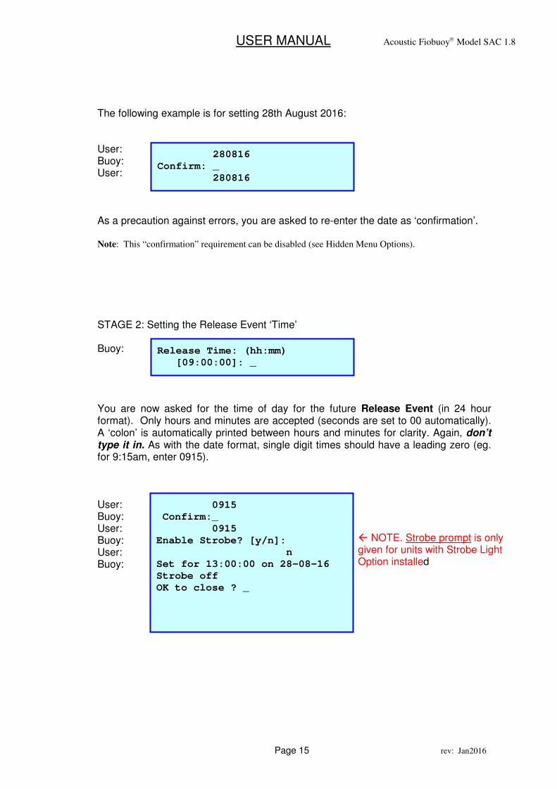
The following example is for setting 28th August 2016: User: Buoy: User: As a precaution against errors, you are asked to re-enter the date as ‘confirmation’. Note: This “confirmation” requirement can be disabled (see Hidden Menu Options).
STAGE 2: Setting the Release Event ‘Time’ Buoy: You are now asked for the time of day for the future Release Event (in 24 hour format). Only hours and minutes are accepted (seconds are set to 00 automatically). A ‘colon’ is automatically printed between hours and minutes for clarity. Again, don’t type it in. As with the date format, single digit times should have a leading zero (eg. for 9:15am, enter 0915). User: Buoy: User: Buoy: User: Buoy:
280816
Confirm: _
280816
0915
Confirm:_
0915
Enable Strobe? [y/n]:
n
Set for 13:00:00 on 28-08-16
Strobe off
OK to close ? _
Release Time: (hh:mm)
[09:00:00]: _
� NOTE. Strobe prompt is only given for units with Strobe Light Option installed
USER MANUAL Acoustic Fiobuoy Model SAC 1.8
Page 16 rev: Jan2016
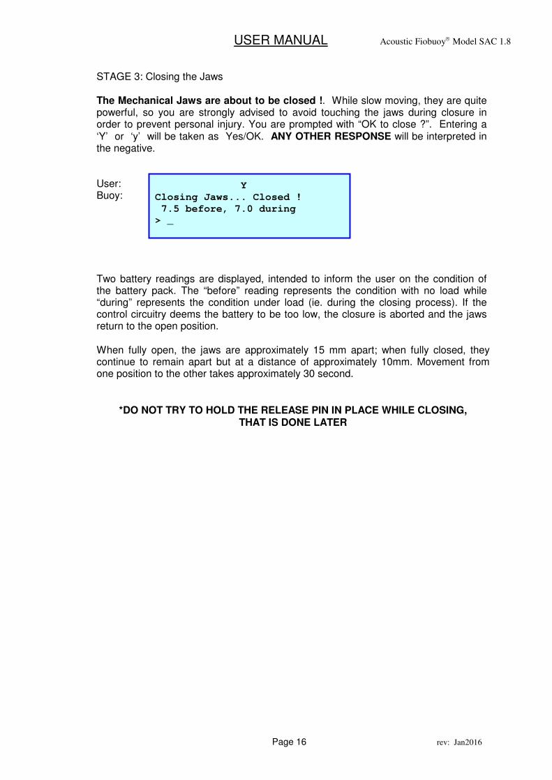
STAGE 3: Closing the Jaws The Mechanical Jaws are about to be closed !. While slow moving, they are quite powerful, so you are strongly advised to avoid touching the jaws during closure in order to prevent personal injury. You are prompted with “OK to close ?”. Entering a ‘Y’ or ‘y’ will be taken as Yes/OK. ANY OTHER RESPONSE will be interpreted in the negative. User: Buoy: Two battery readings are displayed, intended to inform the user on the condition of the battery pack. The “before” reading represents the condition with no load while “during” represents the condition under load (ie. during the closing process). If the control circuitry deems the battery to be too low, the closure is aborted and the jaws return to the open position. When fully open, the jaws are approximately 15 mm apart; when fully closed, they continue to remain apart but at a distance of approximately 10mm. Movement from one position to the other takes approximately 30 second.
*DO NOT TRY TO HOLD THE RELEASE PIN IN PLACE WHILE CLOSING,
THAT IS DONE LATER
Y
Closing Jaws... Closed !
7.5 before, 7.0 during
> _
USER MANUAL Acoustic Fiobuoy Model SAC 1.8
Page 17 rev: Jan2016
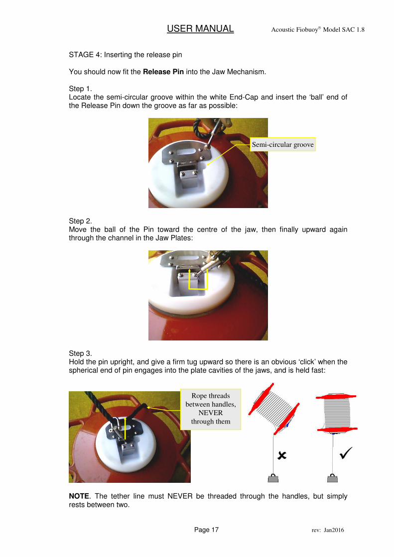
STAGE 4: Inserting the release pin You should now fit the Release Pin into the Jaw Mechanism. Step 1. Locate the semi-circular groove within the white End-Cap and insert the ‘ball’ end of the Release Pin down the groove as far as possible:
Step 2. Move the ball of the Pin toward the centre of the jaw, then finally upward again through the channel in the Jaw Plates:
Step 3. Hold the pin upright, and give a firm tug upward so there is an obvious ‘click’ when the spherical end of pin engages into the plate cavities of the jaws, and is held fast:
NOTE. The tether line must NEVER be threaded through the handles, but simply rests between two.
Semi-circular groove
Rope threads
between handles,
NEVER
through them
USER MANUAL Acoustic Fiobuoy Model SAC 1.8
Page 18 rev: Jan2016
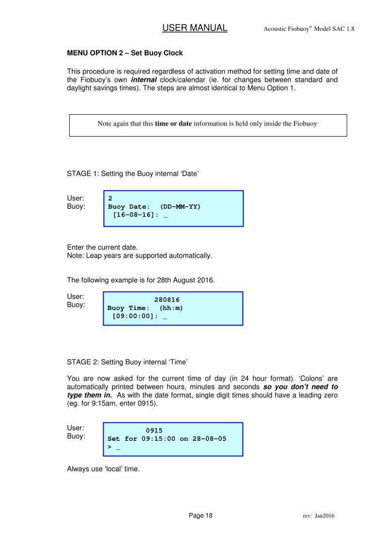
MENU OPTION 2 – Set Buoy Clock
This procedure is required regardless of activation method for setting time and date of the Fiobuoy’s own internal clock/calendar (ie. for changes between standard and daylight savings times). The steps are almost identical to Menu Option 1.
STAGE 1: Setting the Buoy internal ‘Date’ User: Buoy: Enter the current date. Note: Leap years are supported automatically. The following example is for 28th August 2016. User: Buoy: STAGE 2: Setting Buoy internal ‘Time’ You are now asked for the current time of day (in 24 hour format). ‘Colons’ are automatically printed between hours, minutes and seconds so you don’t need to type them in. As with the date format, single digit times should have a leading zero (eg. for 9:15am, enter 0915). User: Buoy: Always use ‘local’ time.
Note again that this time or date information is held only inside the Fiobuoy.
2
Buoy Date: (DD-MM-YY)
[16-08-16]: _
280816
Buoy Time: (hh:m)
[09:00:00]: _
0915
Set for 09:15:00 on 28-08-05
> _
USER MANUAL Acoustic Fiobuoy Model SAC 1.8
Page 19 rev: Jan2016
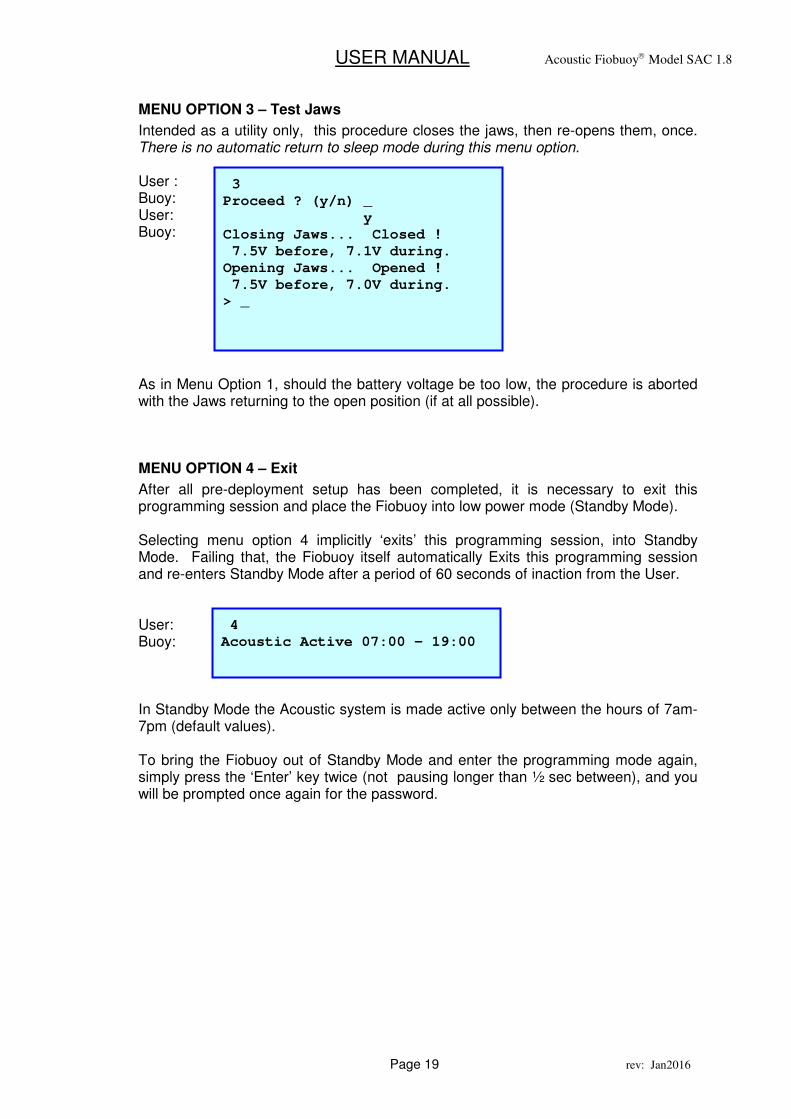
MENU OPTION 3 – Test Jaws
Intended as a utility only, this procedure closes the jaws, then re-opens them, once. There is no automatic return to sleep mode during this menu option. User : Buoy: User: Buoy: As in Menu Option 1, should the battery voltage be too low, the procedure is aborted with the Jaws returning to the open position (if at all possible).
MENU OPTION 4 – Exit
After all pre-deployment setup has been completed, it is necessary to exit this programming session and place the Fiobuoy into low power mode (Standby Mode). Selecting menu option 4 implicitly ‘exits’ this programming session, into Standby Mode. Failing that, the Fiobuoy itself automatically Exits this programming session and re-enters Standby Mode after a period of 60 seconds of inaction from the User. User: Buoy: In Standby Mode the Acoustic system is made active only between the hours of 7am-7pm (default values). To bring the Fiobuoy out of Standby Mode and enter the programming mode again, simply press the ‘Enter’ key twice (not pausing longer than ½ sec between), and you will be prompted once again for the password.
3
Proceed ? (y/n) _
y
Closing Jaws... Closed !
7.5V before, 7.1V during.
Opening Jaws... Opened !
7.5V before, 7.0V during.
> _
4
Acoustic Active 07:00 – 19:00
USER MANUAL Acoustic Fiobuoy Model SAC 1.8
Page 20 rev: Jan2016
POWER CONSERVATION MODES Standby mode is designed to extend battery life. This is achieved in 2 ways: When in Standby Mode, the Fiobuoy electronics, including the acoustic signal detecting sections are shut down for 9 out of every 10 seconds to reduce power consumption. The Fiobuoy is ‘woken’ from Standby Mode, in one of five ways:
1. By the User, via the Direct-Contact Infra-Red Comms port (to program mission parameters etc.)
2. By the User sending an Acoustic Command via the DIU
3. When an actual pre-programmed (timed) Release Event is about to take place.;
4. During its automated, daily diagnosis of battery condition etc.
5. When a ‘leak’ is detected inside the chamber.
After any ‘awakening’, ‘standby’ mode is re-entered automatically following a predetermined period of inaction. Additiona..y, as most recovery operations will occur during daylight hours, the Fiobuoy acoustics electronics are by default, shut down completely between 7pm and 7am, disabling any reception of acoustic communications/commands. Note 1. Pre-programmed Time/Date triggering and Leak Detection still function 24 hours
per day. Infra-red programming is also still always available.
Note 2. The default 12 hour ‘listening band’ (7am to 7pm) can be altered by the User as
required, to increase the length of the listening band, or reduce it further to
conserve battery life. see ‘Adjusting Fiobuoy Acoustic Listening Band’
See section ‘Battery Life’.
USER MANUAL Acoustic Fiobuoy Model SAC 1.8
Page 21 rev: Jan2016
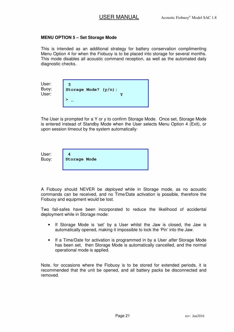
MENU OPTION 5 – Set Storage Mode
This is intended as an additional strategy for battery conservation complimenting Menu Option 4 for when the Fiobuoy is to be placed into storage for several months. This mode disables all acoustic command reception, as well as the automated daily diagnostic checks. User: Buoy: User: The User is prompted for a Y or y to confirm Storage Mode. Once set, Storage Mode is entered instead of Standby Mode when the User selects Menu Option 4 (Exit), or upon session timeout by the system automatically: User: Buoy: A Fiobuoy should NEVER be deployed while in Storage mode, as no acoustic commands can be received, and no Time/Date activation is possible, therefore the Fiobuoy and equipment would be lost. Two fail-safes have been incorporated to reduce the likelihood of accidental deployment while in Storage mode:
• If Storage Mode is ‘set’ by a User whilst the Jaw is closed, the Jaw is automatically opened, making it impossible to lock the ‘Pin’ into the Jaw.
• If a Time/Date for activation is programmed in by a User after Storage Mode has been set, then Storage Mode is automatically cancelled, and the normal operational mode is applied.
Note. for occasions where the Fiobuoy is to be stored for extended periods, it is recommended that the unit be opened, and all battery packs be disconnected and removed.
5
Storage Mode? (y/n):
Y
> _
4
Storage Mode
USER MANUAL Acoustic Fiobuoy Model SAC 1.8
Page 22 rev: Jan2016
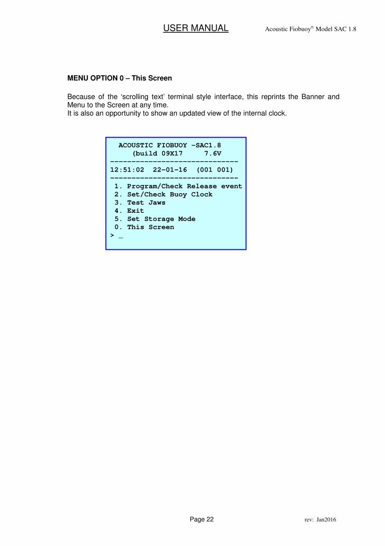
MENU OPTION 0 – This Screen
Because of the ‘scrolling text’ terminal style interface, this reprints the Banner and Menu to the Screen at any time. It is also an opportunity to show an updated view of the internal clock.
ACOUSTIC FIOBUOY –SAC1.8
(build 09X17 7.6V
------------------------------
12:51:02 22-01-16 (001 001)
------------------------------
1. Program/Check Release event
2. Set/Check Buoy Clock
3. Test Jaws
4. Exit
5. Set Storage Mode
0. This Screen
> _
USER MANUAL Acoustic Fiobuoy Model SAC 1.8
Page 23 rev: Jan2016
6. DEPLOYMENT
Successful deployment requires careful preparation and planning before you take to the water. The steps required are:
• Ensure that the internal clock/calendar of the Fiobuoy is set to the current local time and date.
• Ensure that a future Release Event time and date have been programmed and that the jaws are in the closed position.
• Ensure the release pin is properly engaged by the jaw mechanism.
• Fasten the tail end of the tether line to the anchor and/or equipment which is to be submerged.
• It is advisable to perform an ‘in-air’ check of the Acoustic system before deployment.
• Ensure that all details have been properly recorded, such as Serial Number, time and date of backup release and GPS co-ordinates.
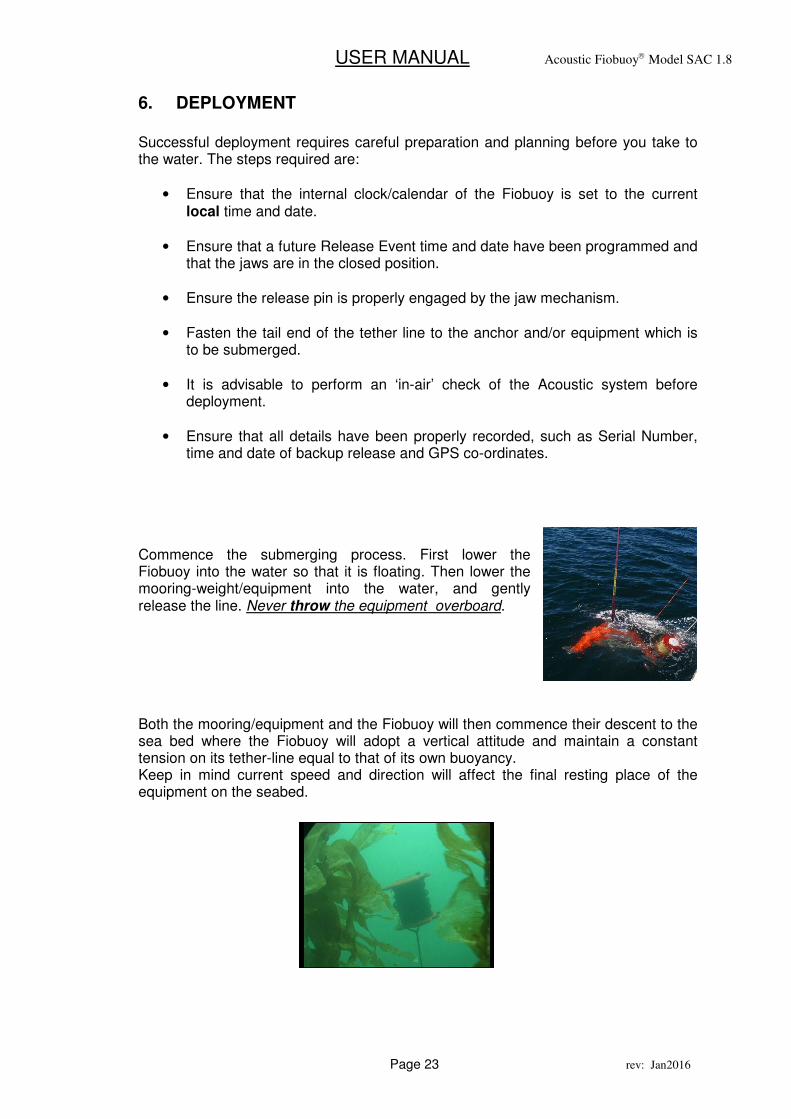
Commence the submerging process. First lower the Fiobuoy into the water so that it is floating. Then lower the mooring-weight/equipment into the water, and gently release the line. Never throw the equipment overboard. Both the mooring/equipment and the Fiobuoy will then commence their descent to the sea bed where the Fiobuoy will adopt a vertical attitude and maintain a constant tension on its tether-line equal to that of its own buoyancy. Keep in mind current speed and direction will affect the final resting place of the equipment on the seabed.
USER MANUAL Acoustic Fiobuoy Model SAC 1.8
Page 24 rev: Jan2016
7. RETRIEVAL
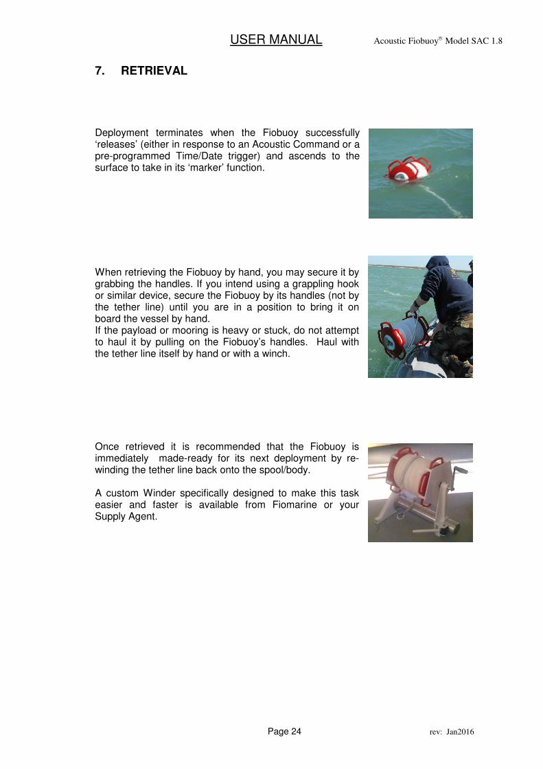
Deployment terminates when the Fiobuoy successfully ‘releases’ (either in response to an Acoustic Command or a pre-programmed Time/Date trigger) and ascends to the surface to take in its ‘marker’ function. When retrieving the Fiobuoy by hand, you may secure it by grabbing the handles. If you intend using a grappling hook or similar device, secure the Fiobuoy by its handles (not by the tether line) until you are in a position to bring it on board the vessel by hand. If the payload or mooring is heavy or stuck, do not attempt to haul it by pulling on the Fiobuoy’s handles. Haul with the tether line itself by hand or with a winch. Once retrieved it is recommended that the Fiobuoy is immediately made-ready for its next deployment by re-winding the tether line back onto the spool/body. A custom Winder specifically designed to make this task easier and faster is available from Fiomarine or your Supply Agent.
USER MANUAL Acoustic Fiobuoy Model SAC 1.8
Page 25 rev: Jan2016
8. BENCH TESTING A ‘TIMED’ RELEASE EVENT
The aim of the following bench test exercise is to enable users to become familiar with the functioning of the Fiobuoy and the processes which occur after it is programmed for a ‘Timed’ Release Event. The Fiobuoy actually brings itself out of Standby mode each day, at the time programmed during Menu Option 1, ie. at the Release Event time. It continues to do so at the same time each day (followed by a resumption of its standby mode) until the day on which the Release Event is scheduled to occur. The test illustrates how the Fiobuoy responds to the automatic wake up by its internal clock/calendar:
• during a day other than the Release Event date; and
• on the day of a programmed Release Event. Ensure that prior to conducting the following tests, the Fiobuoy’s internal clock/calendar has been correctly set with current time and date in accordance with Menu Option 2. With PC & Terminal Program (or Psion) running and plugged in to monitor proceedings, each of the following tests should yield the corresponding screen outputs: (a) Wake up during a day other than the Release Event date
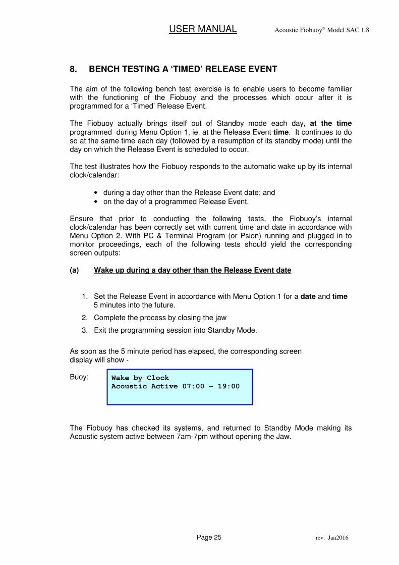
1. Set the Release Event in accordance with Menu Option 1 for a date and time 5 minutes into the future.
2. Complete the process by closing the jaw
3. Exit the programming session into Standby Mode.
As soon as the 5 minute period has elapsed, the corresponding screen display will show - Buoy:
The Fiobuoy has checked its systems, and returned to Standby Mode making its Acoustic system active between 7am-7pm without opening the Jaw.
Wake by Clock
Acoustic Active 07:00 - 19:00
USER MANUAL Acoustic Fiobuoy Model SAC 1.8
Page 26 rev: Jan2016
(b) Wake up on the day of a programmed Release Event
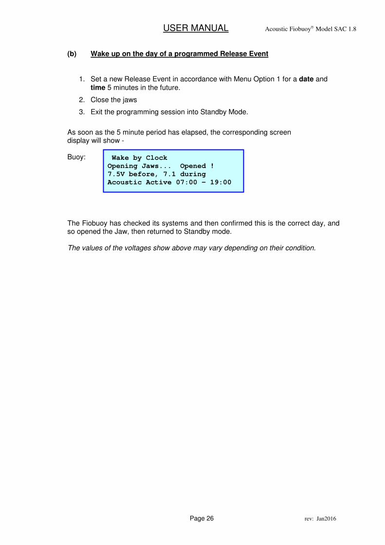
1. Set a new Release Event in accordance with Menu Option 1 for a date and
time 5 minutes in the future.
2. Close the jaws
3. Exit the programming session into Standby Mode.
As soon as the 5 minute period has elapsed, the corresponding screen display will show - Buoy: The Fiobuoy has checked its systems and then confirmed this is the correct day, and so opened the Jaw, then returned to Standby mode. The values of the voltages show above may vary depending on their condition.
Wake by Clock
Opening Jaws... Opened !
7.5V before, 7.1 during
Acoustic Active 07:00 – 19:00
USER MANUAL Acoustic Fiobuoy Model SAC 1.8
Page 27 rev: Jan2016
9. Strobe Light Option
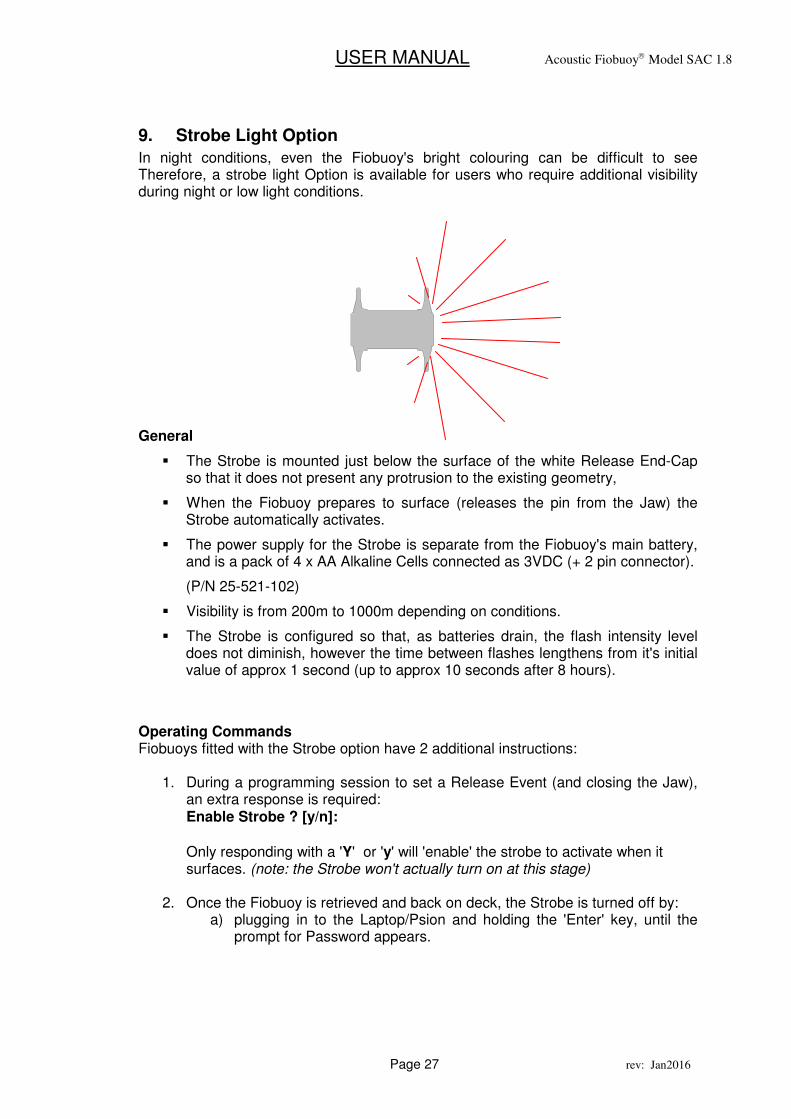
In night conditions, even the Fiobuoy's bright colouring can be difficult to see Therefore, a strobe light Option is available for users who require additional visibility during night or low light conditions. General
� The Strobe is mounted just below the surface of the white Release End-Cap so that it does not present any protrusion to the existing geometry,
� When the Fiobuoy prepares to surface (releases the pin from the Jaw) the Strobe automatically activates.
� The power supply for the Strobe is separate from the Fiobuoy's main battery, and is a pack of 4 x AA Alkaline Cells connected as 3VDC (+ 2 pin connector).
(P/N 25-521-102)
� Visibility is from 200m to 1000m depending on conditions.
� The Strobe is configured so that, as batteries drain, the flash intensity level does not diminish, however the time between flashes lengthens from it's initial value of approx 1 second (up to approx 10 seconds after 8 hours).
Operating Commands Fiobuoys fitted with the Strobe option have 2 additional instructions:
1. During a programming session to set a Release Event (and closing the Jaw), an extra response is required: Enable Strobe ? [y/n]: Only responding with a 'Y' or 'y' will 'enable' the strobe to activate when it surfaces. (note: the Strobe won't actually turn on at this stage)
2. Once the Fiobuoy is retrieved and back on deck, the Strobe is turned off by: a) plugging in to the Laptop/Psion and holding the 'Enter' key, until the
prompt for Password appears.
USER MANUAL Acoustic Fiobuoy Model SAC 1.8
Page 28 rev: Jan2016
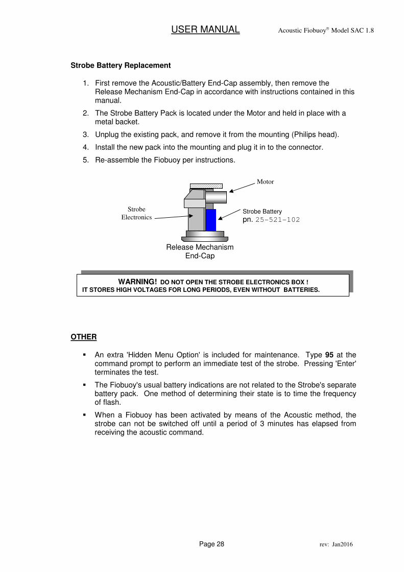
Strobe Battery Replacement
1. First remove the Acoustic/Battery End-Cap assembly, then remove the Release Mechanism End-Cap in accordance with instructions contained in this manual.
2. The Strobe Battery Pack is located under the Motor and held in place with a metal backet.
3. Unplug the existing pack, and remove it from the mounting (Philips head).
4. Install the new pack into the mounting and plug it in to the connector.
5. Re-assemble the Fiobuoy per instructions.
OTHER
� An extra 'Hidden Menu Option' is included for maintenance. Type 95 at the command prompt to perform an immediate test of the strobe. Pressing 'Enter' terminates the test.
� The Fiobuoy's usual battery indications are not related to the Strobe's separate battery pack. One method of determining their state is to time the frequency of flash.
� When a Fiobuoy has been activated by means of the Acoustic method, the strobe can not be switched off until a period of 3 minutes has elapsed from receiving the acoustic command.
WARNING! DO NOT OPEN THE STROBE ELECTRONICS BOX !
IT STORES HIGH VOLTAGES FOR LONG PERIODS, EVEN WITHOUT BATTERIES.
Motor
Release Mechanism End-Cap
Strobe Battery
pn. 25-521-102
Strobe
Electronics
USER MANUAL Acoustic Fiobuoy Model SAC 1.8
Page 29 rev: Jan2016
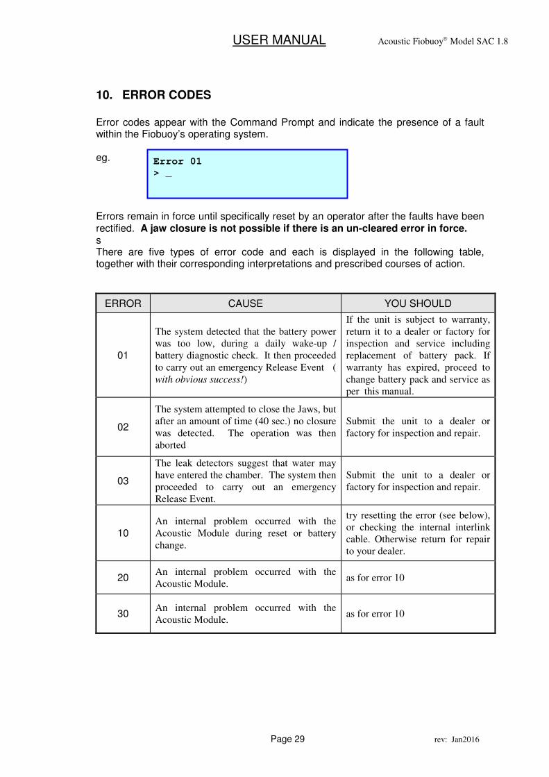
10. ERROR CODES
Error codes appear with the Command Prompt and indicate the presence of a fault within the Fiobuoy’s operating system. eg. Errors remain in force until specifically reset by an operator after the faults have been rectified. A jaw closure is not possible if there is an un-cleared error in force. s There are five types of error code and each is displayed in the following table, together with their corresponding interpretations and prescribed courses of action.
ERROR CAUSE YOU SHOULD
01
The system detected that the battery power
was too low, during a daily wake-up /
battery diagnostic check. It then proceeded
to carry out an emergency Release Event (
with obvious success!)
If the unit is subject to warranty,
return it to a dealer or factory for
inspection and service including
replacement of battery pack. If
warranty has expired, proceed to
change battery pack and service as
per this manual.
02
The system attempted to close the Jaws, but
after an amount of time (40 sec.) no closure
was detected. The operation was then
aborted
Submit the unit to a dealer or
factory for inspection and repair.
03
The leak detectors suggest that water may
have entered the chamber. The system then
proceeded to carry out an emergency
Release Event.
Submit the unit to a dealer or
factory for inspection and repair.
10 An internal problem occurred with the
Acoustic Module during reset or battery
change.
try resetting the error (see below),
or checking the internal interlink
cable. Otherwise return for repair
to your dealer.
20 An internal problem occurred with the
Acoustic Module. as for error 10
30 An internal problem occurred with the
Acoustic Module. as for error 10
Error 01
> _
USER MANUAL Acoustic Fiobuoy Model SAC 1.8
Page 30 rev: Jan2016
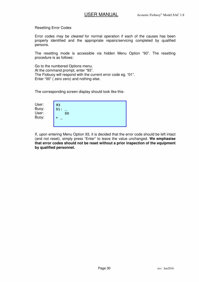
Resetting Error Codes Error codes may be cleared for normal operation if each of the causes has been properly identified and the appropriate repairs/servicing completed by qualified persons. The resetting mode is accessible via hidden Menu Option “93”. The resetting procedure is as follows: Go to the numbered Options menu. At the command prompt, enter “93”. The Fiobuoy will respond with the current error code eg. “01”. Enter “00” ( zero zero) and nothing else. The corresponding screen display should look like this- User: Buoy: User: Buoy: If, upon entering Menu Option 93, it is decided that the error code should be left intact (and not reset), simply press “Enter” to leave the value unchanged. We emphasise that error codes should not be reset without a prior inspection of the equipment by qualified personnel.
93
01: _
00
> _
USER MANUAL Acoustic Fiobuoy Model SAC 1.8
Page 31 rev: Jan2016
11. Battery Life
The anticipated battery life specification is, by necessity, only a best estimate based upon anticipated average use. It should be pointed out though, that a number of factors will affect battery life:
• Primarily the time spent being acoustically ‘active’ (listening)
• The total number of Jaw Actuations,
• The ‘frequency’ of Jaw Actuations,
• The total number of Acoustic signals sent
• Amount of time spent in Storage Mode
• Temperature
• Battery batches and types
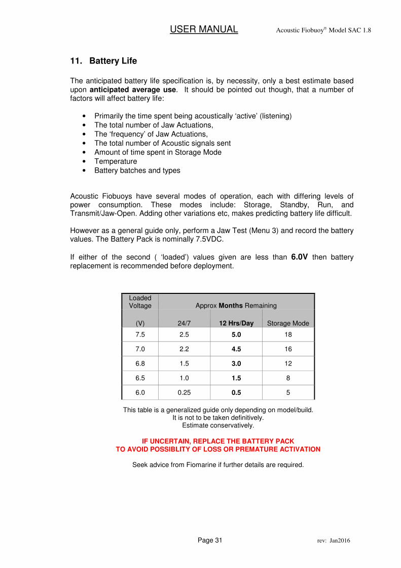
Acoustic Fiobuoys have several modes of operation, each with differing levels of power consumption. These modes include: Storage, Standby, Run, and Transmit/Jaw-Open. Adding other variations etc, makes predicting battery life difficult. However as a general guide only, perform a Jaw Test (Menu 3) and record the battery values. The Battery Pack is nominally 7.5VDC.
If either of the second ( ‘loaded’) values given are less than 6.0V then battery replacement is recommended before deployment.
Loaded Voltage Approx Months Remaining
(V) 24/7 12 Hrs/Day Storage Mode
7.5 2.5 5.0 18
7.0 2.2 4.5 16
6.8 1.5 3.0 12
6.5 1.0 1.5 8
6.0 0.25 0.5 5
This table is a generalized guide only depending on model/build. It is not to be taken definitively.
Estimate conservatively.
IF UNCERTAIN, REPLACE THE BATTERY PACK TO AVOID POSSIBLITY OF LOSS OR PREMATURE ACTIVATION
Seek advice from Fiomarine if further details are required.
USER MANUAL Acoustic Fiobuoy Model SAC 1.8
Page 32 rev: Jan2016
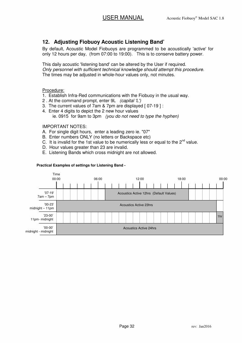
12. Adjusting Fiobuoy Acoustic Listening Band’
By default, Acoustic Model Fiobuoys are programmed to be acoustically 'active' for only 12 hours per day, (from 07:00 to 19:00). This is to conserve battery power. This daily acoustic 'listening band' can be altered by the User if required. Only personnel with sufficient technical knowledge should attempt this procedure. The times may be adjusted in whole-hour values only, not minutes. Procedure: 1. Establish Infra-Red communications with the Fiobuoy in the usual way. 2 . At the command prompt, enter 9L (capital 'L') 3. The current values of 7am & 7pm are displayed [ 07-19 ] : 4. Enter 4 digits to depict the 2 new hour values ie. 0915 for 9am to 3pm (you do not need to type the hyphen) IMPORTANT NOTES: A. For single digit hours, enter a leading zero ie. "07" B. Enter numbers ONLY (no letters or Backspace etc) C. It is invalid for the 1st value to be numerically less or equal to the 2
nd value.
D. Hour values greater than 23 are invalid. E. Listening Bands which cross midnight are not allowed. 00:00
’07-19’ 7am – 7pm
12:00 18:00 00:00
Acoustics Active 12hrs (Default Values)
Acoustics Active 23hrs ’00-23’ midnight – 11pm
1hr ’23-00’ 11pm- midnight
06:00
Practical Examples of settings for Listening Band -
Time
Acoustics Active 24hrs ’00-00’ midnight - midnight

USER MANUAL Acoustic Fiobuoy Model SAC 1.8
Page 33 rev: Jan2016
13. MAINTENANCE
General The Fiobuoy has been constructed with a minimum of moving parts and therefore, requires minimum maintenance where moderate deployments are envisaged. With average use under moderate conditions, we recommend that servicing/maintenance be undertaken every 6-12 months. With a higher frequency of use under more extreme conditions, servicing and maintenance should be undertaken every 3-6 months if possible. All maintenance should be carried out by suitably trained personnel.
USER MANUAL Acoustic Fiobuoy Model SAC 1.8
Page 34 rev: Jan2016
External Maintenance
1. Immediately prior to and following each deployment, inspect the white End-
Cap for signs of any cracking around the clamping mechanism. Contact either your local dealer or Fiomarine for further instructions should you detect any such wear or damage.
2. Inspect for any marine growth and debris, particularly around the release
mechanism and communications socket. Remove any obstruction with a stiff brush.
3. Immediately following each deployment and during the process of rewinding
the rope on to the Fiobuoy, inspect the rope for any appreciable wear and replace if necessary. Also inspect the shackles and other rope attachments to ensure they are properly secure.
4. In the event the Fiobuoy is to be either placed into storage or, not used for an
extended period rinse the Fiobuoy and its rope and attachments with fresh water before stowing away. (it is also recommended to remove the battery for long storage)
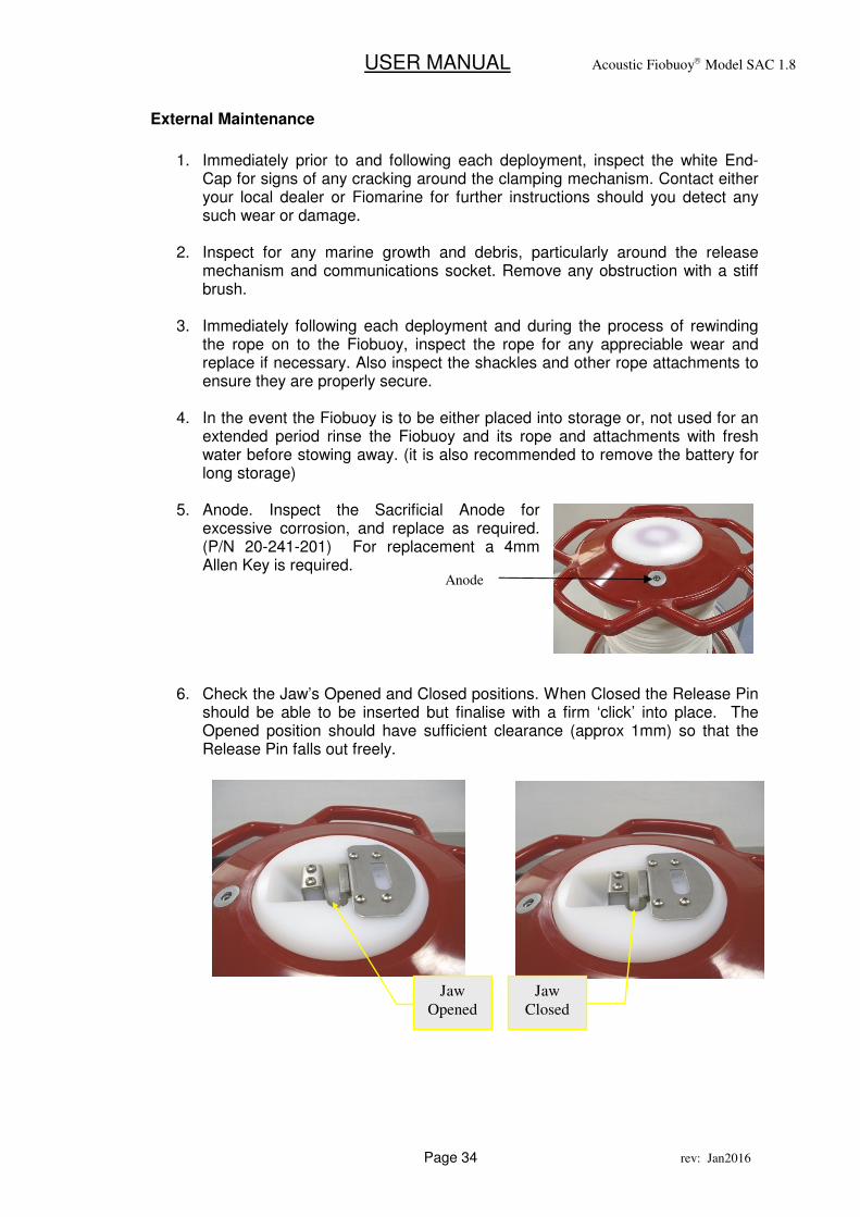
5. Anode. Inspect the Sacrificial Anode for
excessive corrosion, and replace as required. (P/N 20-241-201) For replacement a 4mm Allen Key is required.
6. Check the Jaw’s Opened and Closed positions. When Closed the Release Pin should be able to be inserted but finalise with a firm ‘click’ into place. The Opened position should have sufficient clearance (approx 1mm) so that the Release Pin falls out freely.
Anode
Jaw
Opened
Jaw
Closed
USER MANUAL Acoustic Fiobuoy Model SAC 1.8
Page 35 rev: Jan2016
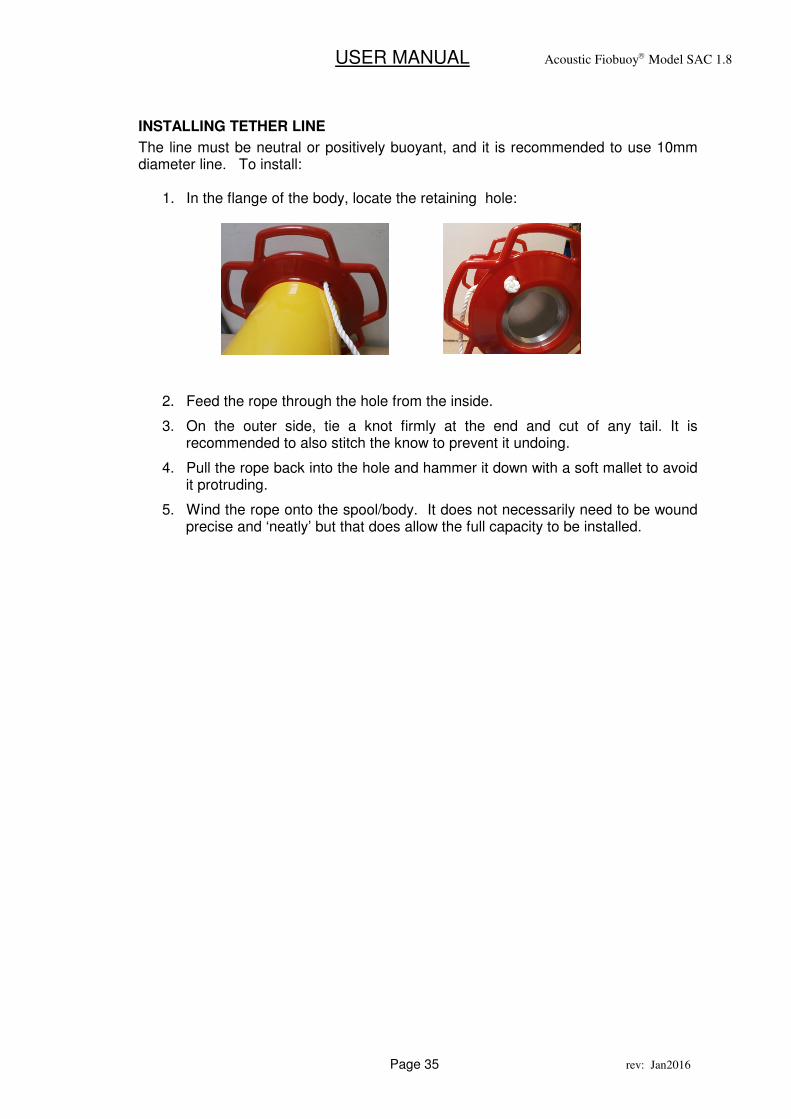
INSTALLING TETHER LINE
The line must be neutral or positively buoyant, and it is recommended to use 10mm diameter line. To install:
1. In the flange of the body, locate the retaining hole:
2. Feed the rope through the hole from the inside.
3. On the outer side, tie a knot firmly at the end and cut of any tail. It is recommended to also stitch the know to prevent it undoing.
4. Pull the rope back into the hole and hammer it down with a soft mallet to avoid it protruding.
5. Wind the rope onto the spool/body. It does not necessarily need to be wound precise and ‘neatly’ but that does allow the full capacity to be installed.
USER MANUAL Acoustic Fiobuoy Model SAC 1.8
Page 36 rev: Jan2016
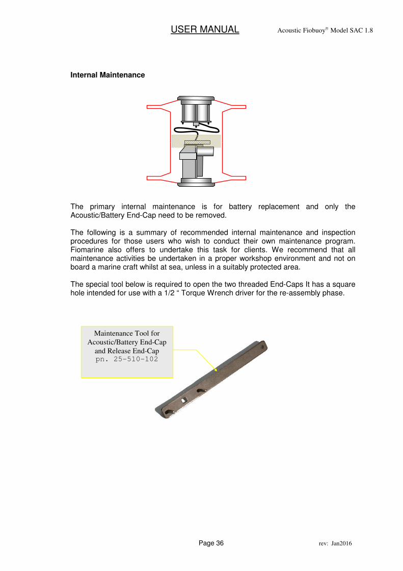
Internal Maintenance
The primary internal maintenance is for battery replacement and only the Acoustic/Battery End-Cap need to be removed. The following is a summary of recommended internal maintenance and inspection procedures for those users who wish to conduct their own maintenance program. Fiomarine also offers to undertake this task for clients. We recommend that all maintenance activities be undertaken in a proper workshop environment and not on board a marine craft whilst at sea, unless in a suitably protected area. The special tool below is required to open the two threaded End-Caps It has a square hole intended for use with a 1/2 “ Torque Wrench driver for the re-assembly phase.
Maintenance Tool for
Acoustic/Battery End-Cap
and Release End-Cap pn. 25-510-102
USER MANUAL Acoustic Fiobuoy Model SAC 1.8
Page 37 rev: Jan2016
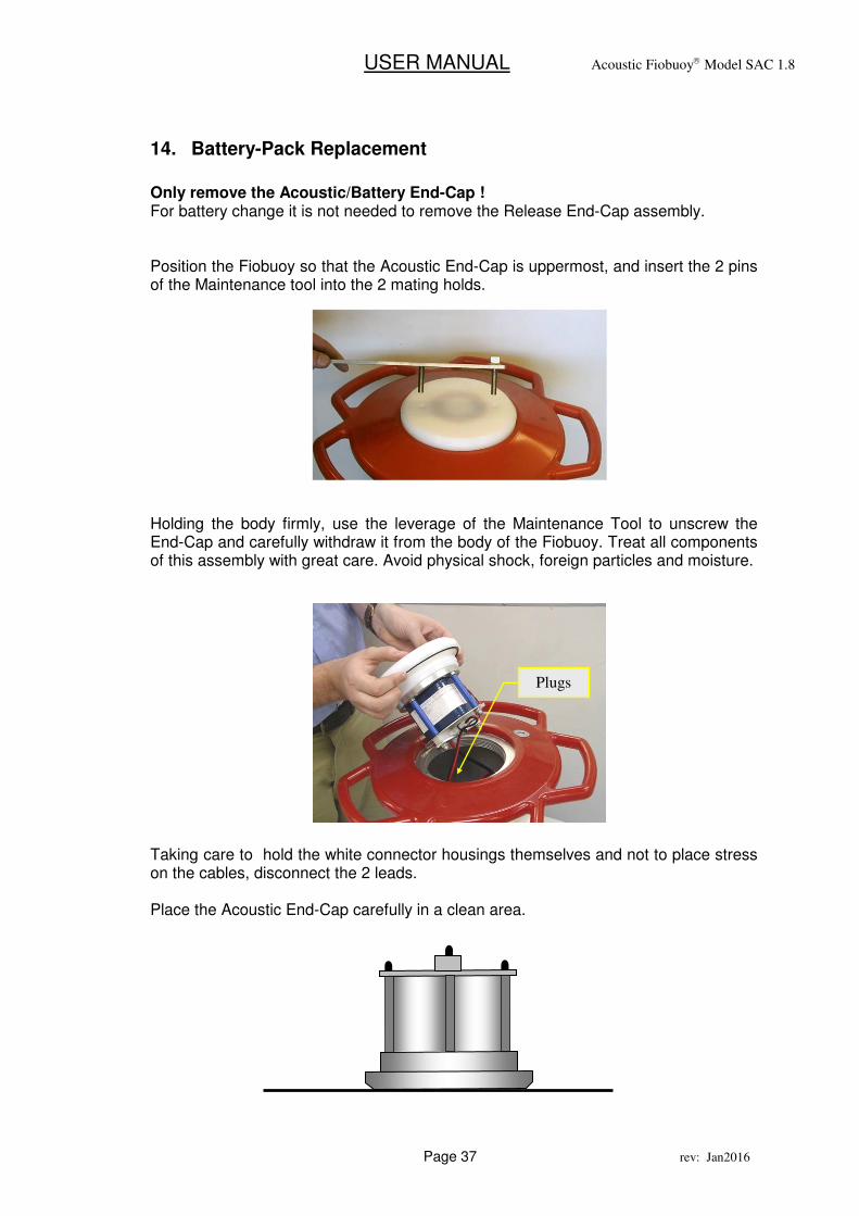
14. Battery-Pack Replacement
Only remove the Acoustic/Battery End-Cap ! For battery change it is not needed to remove the Release End-Cap assembly. Position the Fiobuoy so that the Acoustic End-Cap is uppermost, and insert the 2 pins of the Maintenance tool into the 2 mating holds. Holding the body firmly, use the leverage of the Maintenance Tool to unscrew the End-Cap and carefully withdraw it from the body of the Fiobuoy. Treat all components of this assembly with great care. Avoid physical shock, foreign particles and moisture. Taking care to hold the white connector housings themselves and not to place stress on the cables, disconnect the 2 leads. Place the Acoustic End-Cap carefully in a clean area.
Plugs
USER MANUAL Acoustic Fiobuoy Model SAC 1.8
Page 38 rev: Jan2016
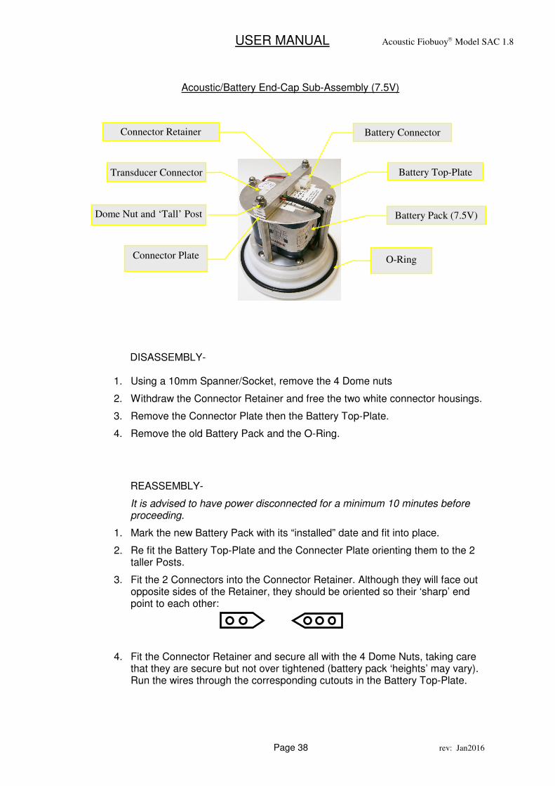
DISASSEMBLY-
1. Using a 10mm Spanner/Socket, remove the 4 Dome nuts
2. Withdraw the Connector Retainer and free the two white connector housings.
3. Remove the Connector Plate then the Battery Top-Plate.
4. Remove the old Battery Pack and the O-Ring.
REASSEMBLY-
It is advised to have power disconnected for a minimum 10 minutes before proceeding.
1. Mark the new Battery Pack with its “installed” date and fit into place.
2. Re fit the Battery Top-Plate and the Connecter Plate orienting them to the 2 taller Posts.
3. Fit the 2 Connectors into the Connector Retainer. Although they will face out opposite sides of the Retainer, they should be oriented so their ‘sharp’ end point to each other:
4. Fit the Connector Retainer and secure all with the 4 Dome Nuts, taking care that they are secure but not over tightened (battery pack ‘heights’ may vary). Run the wires through the corresponding cutouts in the Battery Top-Plate.
Acoustic/Battery End-Cap Sub-Assembly (7.5V)
Battery Top-Plate
Connector Retainer Battery Connector
Transducer Connector
Dome Nut and ‘Tall’ Post
O-Ring
Battery Pack (7.5V)
Connector Plate
USER MANUAL Acoustic Fiobuoy Model SAC 1.8
Page 39 rev: Jan2016
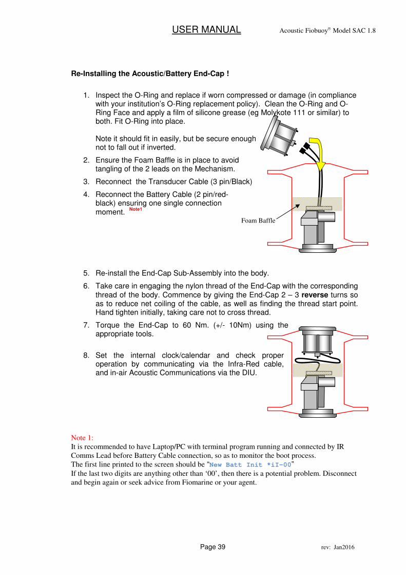
Re-Installing the Acoustic/Battery End-Cap !
1. Inspect the O-Ring and replace if worn compressed or damage (in compliance with your institution’s O-Ring replacement policy). Clean the O-Ring and O-Ring Face and apply a film of silicone grease (eg Molykote 111 or similar) to both. Fit O-Ring into place. Note it should fit in easily, but be secure enough not to fall out if inverted.
2. Ensure the Foam Baffle is in place to avoid tangling of the 2 leads on the Mechanism.
3. Reconnect the Transducer Cable (3 pin/Black)
4. Reconnect the Battery Cable (2 pin/red-black) ensuring one single connection moment.
Note1
5. Re-install the End-Cap Sub-Assembly into the body.
6. Take care in engaging the nylon thread of the End-Cap with the corresponding thread of the body. Commence by giving the End-Cap 2 – 3 reverse turns so as to reduce net coiling of the cable, as well as finding the thread start point. Hand tighten initially, taking care not to cross thread.
7. Torque the End-Cap to 60 Nm. (+/- 10Nm) using the appropriate tools.
8. Set the internal clock/calendar and check proper operation by communicating via the Infra-Red cable, and in-air Acoustic Communications via the DIU.
Note 1:
It is recommended to have Laptop/PC with terminal program running and connected by IR
Comms Lead before Battery Cable connection, so as to monitor the boot process.
The first line printed to the screen should be “New Batt Init *iI-00”
If the last two digits are anything other than ‘00’, then there is a potential problem. Disconnect
and begin again or seek advice from Fiomarine or your agent.
Foam Baffle
USER MANUAL Acoustic Fiobuoy Model SAC 1.8
Page 40 rev: Jan2016
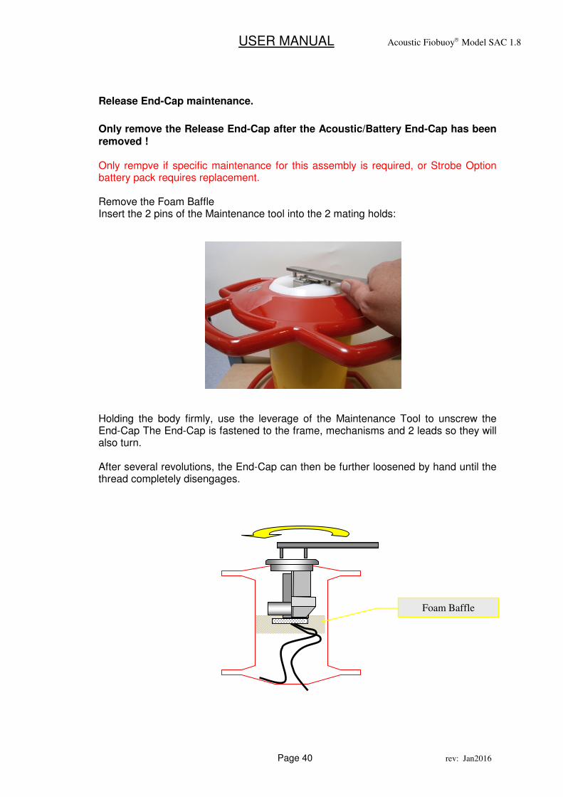
Release End-Cap maintenance.
Only remove the Release End-Cap after the Acoustic/Battery End-Cap has been removed ! Only rempve if specific maintenance for this assembly is required, or Strobe Option battery pack requires replacement. Remove the Foam Baffle Insert the 2 pins of the Maintenance tool into the 2 mating holds: Holding the body firmly, use the leverage of the Maintenance Tool to unscrew the End-Cap The End-Cap is fastened to the frame, mechanisms and 2 leads so they will also turn. After several revolutions, the End-Cap can then be further loosened by hand until the thread completely disengages.
Foam Baffle
USER MANUAL Acoustic Fiobuoy Model SAC 1.8
Page 41 rev: Jan2016
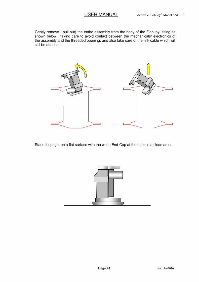
Gently remove ( pull out) the entire assembly from the body of the Fiobuoy, tilting as shown below, taking care to avoid contact between the mechanicals/ electronics of the assembly and the threaded opening, and also take care of the link cable which will still be attached.
Stand it upright on a flat surface with the white End-Cap at the base in a clean area.

USER MANUAL Acoustic Fiobuoy Model SAC 1.8
Page 42 rev: Jan2016
NEVER REMOVE THE RELEASE MECHANISM END-CAP FIRST !
Doing so may cause the internal cables to tangle during the unscrewing process and damage the unit.
ALWAYS REMOVE THE ACOUSTIC END-CAP FIRST !
Release Mechanism
Electronic Control PCB
O-Ring Seal
Acoustic Module
Motor
Leak Sensors
Battery and Transducer
cables
�
�
Release Mechanism End-Cap Assembly
USER MANUAL Acoustic Fiobuoy Model SAC 1.8
Page 43 rev: Jan2016
Inspection and service – Release End-Cap
1. Examine the aluminium O-Ring Face of the Body for any corrosion or foreign
particles (grit or hairs etc) which may compromise the water seal.
2. Inspect the O-Ring and replace if worn, compressed or damage (in compliance with your institution’s O-Ring replacement policy). Clean the O-ring groove for any foreign particles. Apply a film of silicone grease (eg Molykote 111 or similar) to the O-Ring and fit into place.
a. Note it should fit in easily, but be firmly enough not to fall out if inverted.
b. It should extend slightly proud above the white plastic base.
3. Examine both the chamber of the Fiobuoy body, the Acoustic End-Cap Assembly and the Mechanism Assembly for evidence of any moisture. (Where any moisture is detected, contact Fiomarine for further assistance.
4. The motor and gearbox assembly are factory lubricated for life and should not
require any further attention.
5. Lead screw and clevis nut - apply Castrol LM grease (or equivalent) sparingly to the lead screw every 12 months.
6. The thread of the white End-Cap sis self lubricating but should be kept clean and free of foreign particles.
USER MANUAL Acoustic Fiobuoy Model SAC 1.8
Page 44 rev: Jan2016
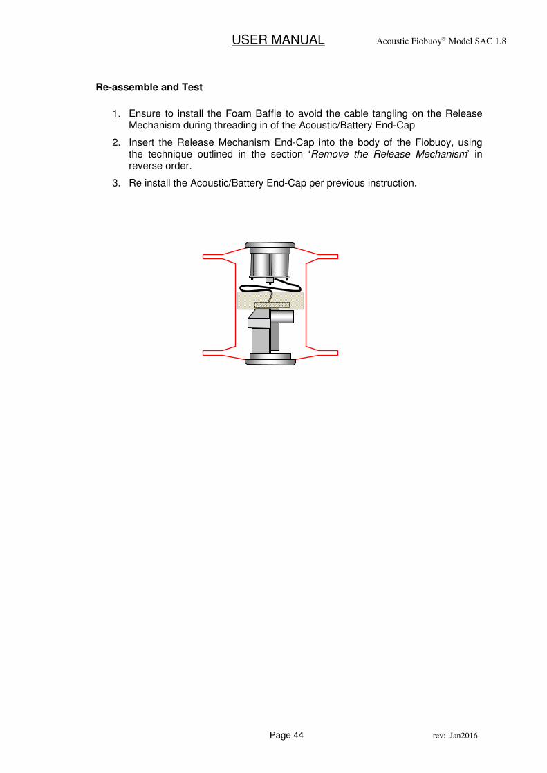
Re-assemble and Test
1. Ensure to install the Foam Baffle to avoid the cable tangling on the Release
Mechanism during threading in of the Acoustic/Battery End-Cap
2. Insert the Release Mechanism End-Cap into the body of the Fiobuoy, using the technique outlined in the section ‘Remove the Release Mechanism’ in reverse order.
3. Re install the Acoustic/Battery End-Cap per previous instruction.
USER MANUAL Acoustic Fiobuoy Model SAC 1.8
Page 45 rev: Jan2016
15. HIDDEN MENU OPTIONS
Access to special functions not listed in the menu is available via the following options. Each option, eg.”91” etc. is entered at the command prompt of the Fiobuoy itself.
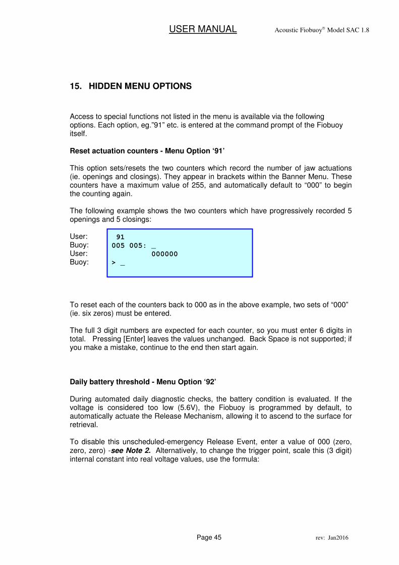
Reset actuation counters - Menu Option ‘91’ This option sets/resets the two counters which record the number of jaw actuations (ie. openings and closings). They appear in brackets within the Banner Menu. These counters have a maximum value of 255, and automatically default to “000” to begin the counting again. The following example shows the two counters which have progressively recorded 5 openings and 5 closings: User: Buoy: User: Buoy: To reset each of the counters back to 000 as in the above example, two sets of “000” (ie. six zeros) must be entered. The full 3 digit numbers are expected for each counter, so you must enter 6 digits in total. Pressing [Enter] leaves the values unchanged. Back Space is not supported; if you make a mistake, continue to the end then start again. Daily battery threshold - Menu Option ‘92’ During automated daily diagnostic checks, the battery condition is evaluated. If the voltage is considered too low (5.6V), the Fiobuoy is programmed by default, to automatically actuate the Release Mechanism, allowing it to ascend to the surface for retrieval. To disable this unscheduled-emergency Release Event, enter a value of 000 (zero, zero, zero) -see Note 2. Alternatively, to change the trigger point, scale this (3 digit) internal constant into real voltage values, use the formula:
91
005 005: _
000000
> _
USER MANUAL Acoustic Fiobuoy Model SAC 1.8
Page 46 rev: Jan2016
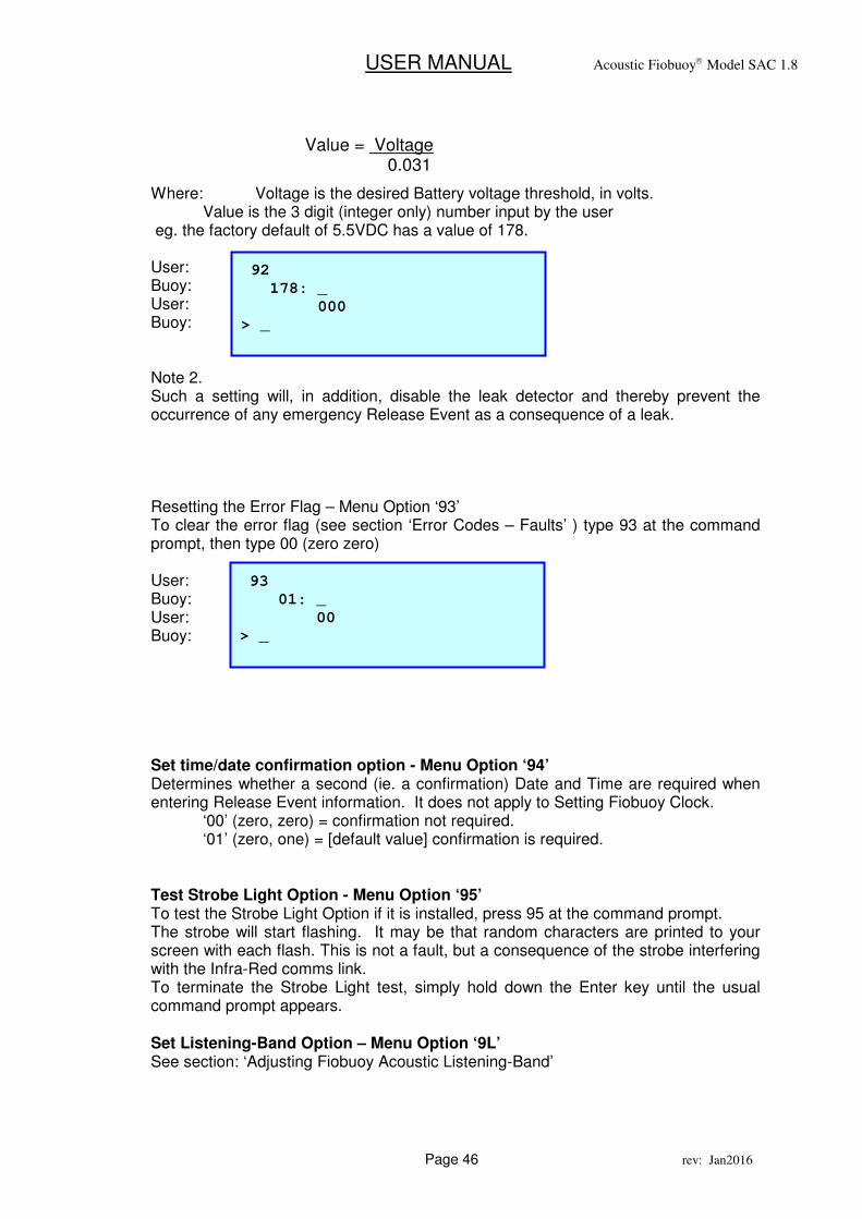
Where: Voltage is the desired Battery voltage threshold, in volts. Value is the 3 digit (integer only) number input by the user eg. the factory default of 5.5VDC has a value of 178. User: Buoy: User: Buoy: Note 2. Such a setting will, in addition, disable the leak detector and thereby prevent the occurrence of any emergency Release Event as a consequence of a leak. Resetting the Error Flag – Menu Option ‘93’ To clear the error flag (see section ‘Error Codes – Faults’ ) type 93 at the command prompt, then type 00 (zero zero) User: Buoy: User: Buoy: Set time/date confirmation option - Menu Option ‘94’ Determines whether a second (ie. a confirmation) Date and Time are required when entering Release Event information. It does not apply to Setting Fiobuoy Clock. ‘00’ (zero, zero) = confirmation not required. ‘01’ (zero, one) = [default value] confirmation is required.
Test Strobe Light Option - Menu Option ‘95’ To test the Strobe Light Option if it is installed, press 95 at the command prompt. The strobe will start flashing. It may be that random characters are printed to your screen with each flash. This is not a fault, but a consequence of the strobe interfering with the Infra-Red comms link. To terminate the Strobe Light test, simply hold down the Enter key until the usual command prompt appears. Set Listening-Band Option – Menu Option ‘9L’ See section: ‘Adjusting Fiobuoy Acoustic Listening-Band’
92
178: _
000
> _
Value = Voltage 0.031
93
01: _
00
> _
USER MANUAL Acoustic Fiobuoy Model SAC 1.8
Page 47 rev: Jan2016
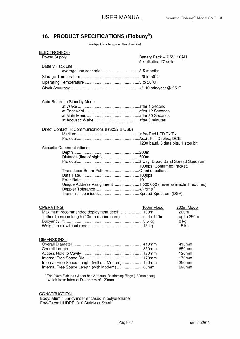
16. PRODUCT SPECIFICATIONS (Fiobuoy®)
ELECTRONICS -
Power Supply Battery Pack – 7.5V, 10AH 5 x alkaline ‘D’ cells Battery Pack Life: average use scenario ..................................3-5 months
Storage Temperature ....................................................-20 to 50°C
Operating Temperature .................................................3 to 50°C
Clock Accuracy ..............................................................+/- 10 min/year @ 25°C Auto Return to Standby Mode at Wake .......................................................after 1 Second at Password .................................................after 12 Seconds at Main Menu ...............................................after 30 Seconds at Acoustic Wake .........................................after 3 minutes Direct Contact IR Communications (RS232 & USB) Medium ........................................................Infra-Red LED Tx/Rx Protocol ........................................................Ascii, Full Duplex, DCE, 1200 baud, 8 data bits, 1 stop bit. Acoustic Communications: Depth ...........................................................200m Distance (line of sight) .................................500m Protocol ........................................................2 way, Broad Band Spread Spectrum 100bps, Confirmed Packet. Transducer Beam Pattern ...........................Omni-directional Data Rate .....................................................100bps Error Rate ....................................................10
-6
Unique Address Assignment .......................1,000,000 (move available if required) Doppler Tolerance .......................................+/- 5ms
-1
Transmit Technique .....................................Spread Spectrum (DSP)
OPERATING - 100m Model 200m Model
Maximum recommended deployment depth………… ...... 100m 200m Tether line/rope length (10mm marine cord) .................... up to 120m up to 250m Buoyancy lift ..................................................................... 3.5 kg 8 kg Weight in air without rope ................................................. 13 kg 15 kg
DIMENSIONS -
Overall Diameter ............................................................... 410mm 410mm Overall Length .................................................................. 350mm 650mm Access Hole to Cavity ....................................................... 120mm 120mm Internal Free Space Dia ................................................... 170mm 170mm
i
Internal Free Space Length (without Modem) .................. 120mm 350mm Internal Free Space Length (with Modem) ....................... 60mm 290mm
1 The 200m Fiobuoy cylinder has 2 internal Reinforcing Rings (180mm apart)
which have internal Diameters of 120mm
CONSTRUCTION - Body: Aluminium cylinder encased in polyurethane End-Caps: UHDPE, 316 Stainless Steel.
(subject to change without notice)

USER MANUAL Acoustic Fiobuoy Model SAC 1.8
Page 48 rev: Jan2016
USER MANUAL Acoustic Fiobuoy Model SAC 1.8
Page 49 rev: Jan2016
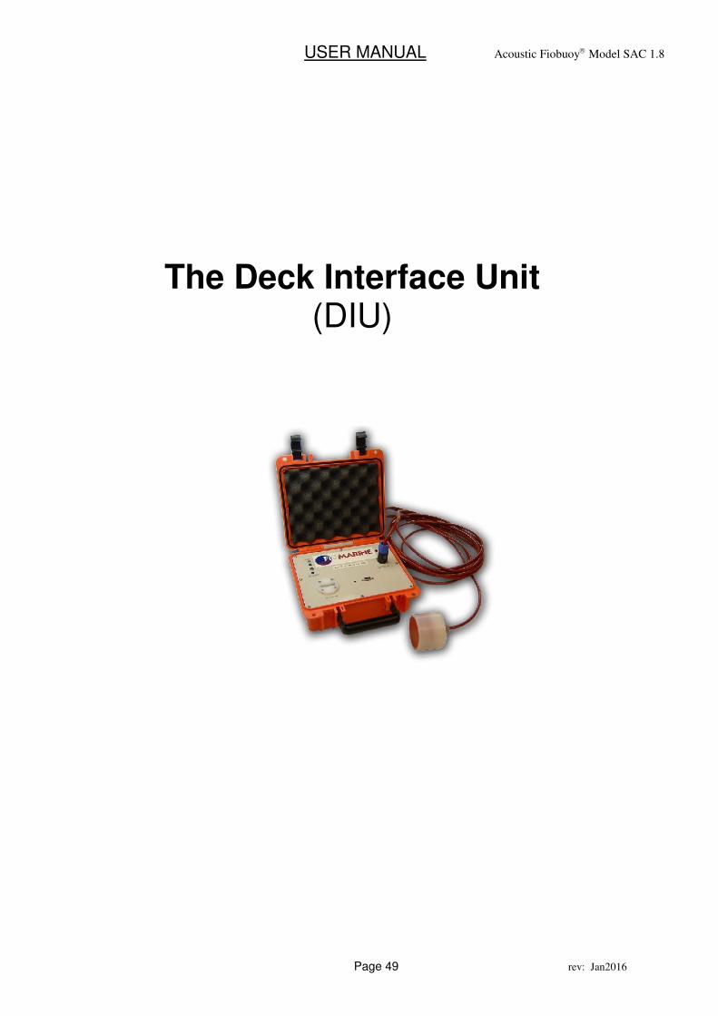
The Deck Interface Unit (DIU)
USER MANUAL Acoustic Fiobuoy Model SAC 1.8
Page 50 rev: Jan2016
17. OPERATING PROCEDURES
Overview:
The primary function of the DIU is to act as an interface between the terminal (Psion/Laptop etc) and a deployed Fiobuoy. It accepts commands input at the terminal via the direct contact Infra-Red lead, creates an appropriate acoustic signal and transmits that via the Dunking Transducer through the water to the deployed Fiobuoy. Additionally, the DIU unit waits for acoustic ‘acknowledgments’ or data from the deployed Fiobuoy, decodes their meaning and context, and reports them to the terminal screen via the Infra-Red lead for the User. Proceedure Assuming your Fiobuoy is active and appropriately deployed:
• Connect the Acoustic Dunking Transducer to the DIU in the appropriate socket.
Note, this is a bayonet style plug/socket. To plug in, align the keyway slots and insert, then turn cw 90º. To remove, pull the chrome catch back toward you with your thumb, then turn ccw 90º, and withdraw the plug from the socket.
• Connect the PC/Laptop (or Psion WorkAbout) with terminal program running to the DIU via the Direct-Contact Infra-Red Comms Cable, and switch the DCU ON.
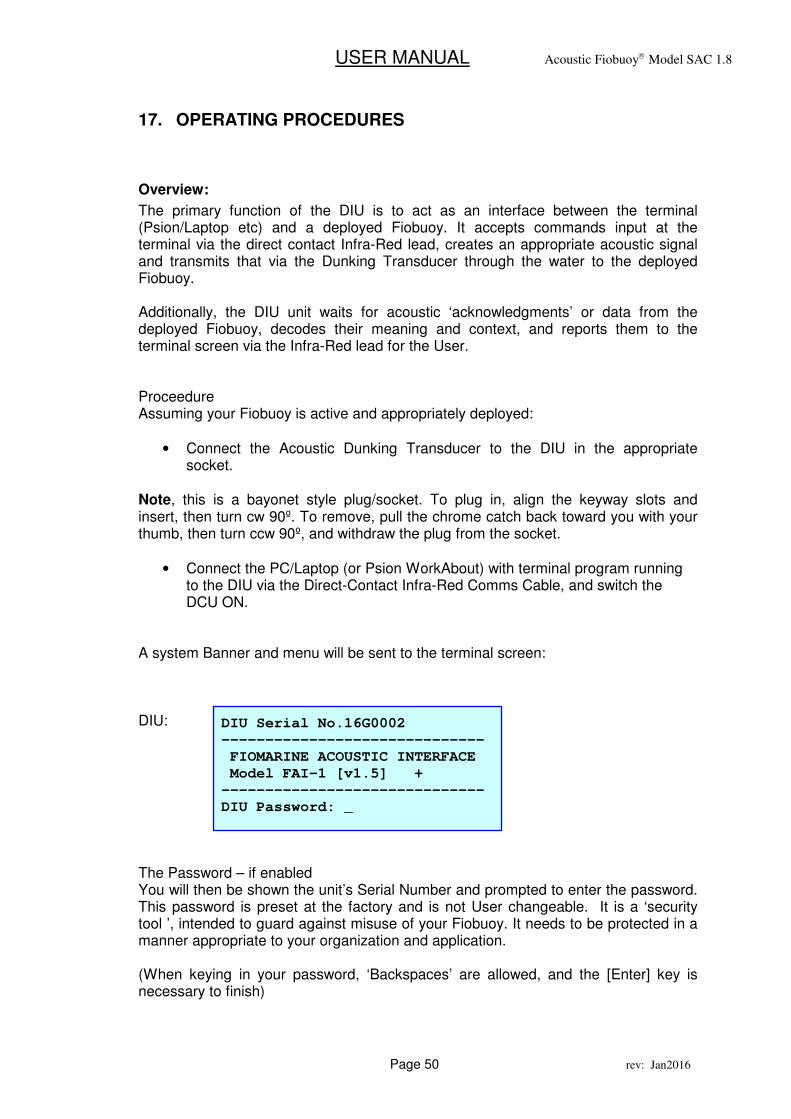
A system Banner and menu will be sent to the terminal screen: DIU: The Password – if enabled You will then be shown the unit’s Serial Number and prompted to enter the password. This password is preset at the factory and is not User changeable. It is a ‘security tool ’, intended to guard against misuse of your Fiobuoy. It needs to be protected in a manner appropriate to your organization and application. (When keying in your password, ‘Backspaces’ are allowed, and the [Enter] key is necessary to finish)
DIU Serial No.16G0002
------------------------------
FIOMARINE ACOUSTIC INTERFACE
Model FAI-1 [v1.5] +
------------------------------
DIU Password: _
USER MANUAL Acoustic Fiobuoy Model SAC 1.8
Page 51 rev: Jan2016
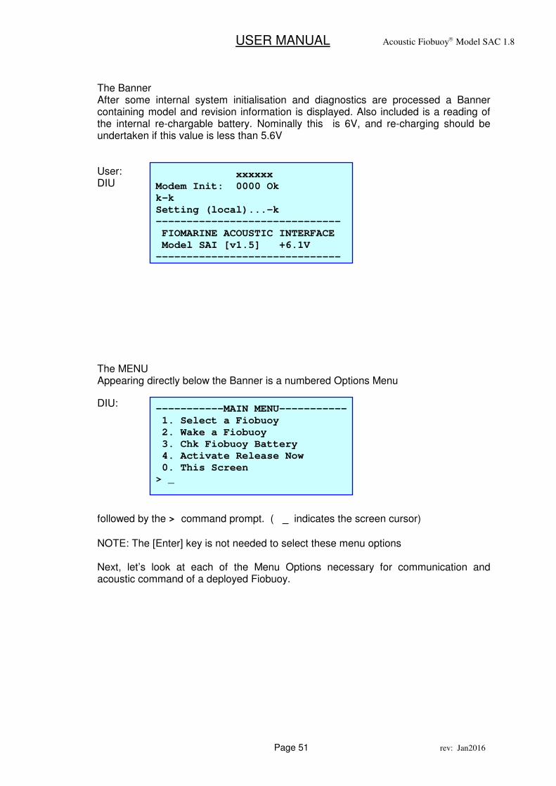
The Banner After some internal system initialisation and diagnostics are processed a Banner containing model and revision information is displayed. Also included is a reading of the internal re-chargable battery. Nominally this is 6V, and re-charging should be undertaken if this value is less than 5.6V User: DIU
The MENU Appearing directly below the Banner is a numbered Options Menu
DIU:
followed by the > command prompt. ( _ indicates the screen cursor)
NOTE: The [Enter] key is not needed to select these menu options Next, let’s look at each of the Menu Options necessary for communication and acoustic command of a deployed Fiobuoy.
-----------MAIN MENU-----------
1. Select a Fiobuoy
2. Wake a Fiobuoy
3. Chk Fiobuoy Battery
4. Activate Release Now
0. This Screen
> _
xxxxxx
Modem Init: 0000 Ok
k-k
Setting (local)...-k
------------------------------
FIOMARINE ACOUSTIC INTERFACE
Model SAI [v1.5] +6.1V
------------------------------
USER MANUAL Acoustic Fiobuoy Model SAC 1.8
Page 52 rev: Jan2016
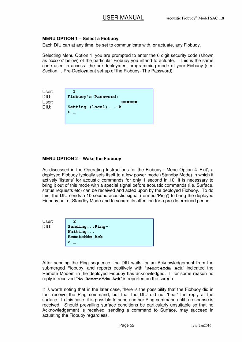
MENU OPTION 1 – Select a Fiobuoy.
Each DIU can at any time, be set to communicate with, or actuate, any Fiobuoy. Selecting Menu Option 1, you are prompted to enter the 6 digit security code (shown as ‘xxxxxx’ below) of the particular Fiobuoy you intend to actuate. This is the same code used to access the pre-deployment programming mode of your Fiobuoy (see Section 1, Pre-Deployment set-up of the Fiobuoy- The Password). User: DIU: User: DIU:
MENU OPTION 2 – Wake the Fiobuoy
As discussed in the Operating Instructions for the Fiobuoy - Menu Option 4 ‘Exit’, a deployed Fiobuoy typically sets itself to a low power mode (Standby Mode) in which it actively ‘listens’ for acoustic commands for only 1 second in 10. It is necessary to bring it out of this mode with a special signal before acoustic commands (i.e. Surface, status requests etc) can be received and acted upon by the deployed Fiobuoy. To do this, the DIU sends a 10 second acoustic signal (termed ‘Ping’) to bring the deployed Fiobuoy out of Standby Mode and to secure its attention for a pre-determined period. User: DIU: After sending the Ping sequence, the DIU waits for an Acknowledgement from the submerged Fiobuoy, and reports positively with “RemoteMdm Ack” indicated the
Remote Modem in the deployed Fiobuoy has acknowledged. If for some reason no reply is received “No RemoteMdm Ack” is reported on the screen.
It is worth noting that in the later case, there is the possibility that the Fiobuoy did in fact receive the Ping command, but that the DIU did not ‘hear’ the reply at the surface. In this case, it is possible to send another Ping command until a response is received. Should prevailing surface conditions be particularly unsuitable so that no Acknowledgement is received, sending a command to Surface, may succeed in actuating the Fiobuoy regardless.
2
Sending...Ping-
Waiting...
RemoteMdm Ack
> _
1
Fiobuoy's Password:
xxxxxx
Setting (local)...-k
> _
USER MANUAL Acoustic Fiobuoy Model SAC 1.8
Page 53 rev: Jan2016
Once active in Acoustic Mode (not in Standby Mode) the Fiobuoy can receive any number of acoustic commands or enquiries, but can not be communicated with via the Direct-Contact Infra-Red Comms Cable (ie. bench testing etc.). If no acoustic signal is received by the Fiobuoy for a period of 3 minutes, it automatically returns to ‘Standby Mode’. Each time an acoustic signal is received the 3 minute timer is restarted.
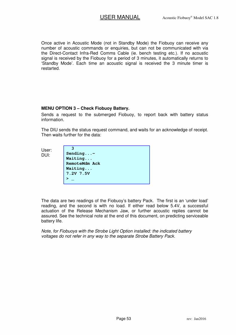
MENU OPTION 3 – Check Fiobuoy Battery.
Sends a request to the submerged Fiobuoy, to report back with battery status information. The DIU sends the status request command, and waits for an acknowledge of receipt. Then waits further for the data: User: DUI: The data are two readings of the Fiobuoy’s battery Pack. The first is an ‘under load’ reading, and the second is with no load. If either read below 5.4V, a successful actuation of the Release Mechanism Jaw, or further acoustic replies cannot be assured. See the technical note at the end of this document, on predicting serviceable battery life. Note, for Fiobuoys with the Strobe Light Option installed: the indicated battery voltages do not refer in any way to the separate Strobe Battery Pack.
3
Sending...-
Waiting...
RemoteMdm Ack
Waiting...
7.2V 7.5V
> _
USER MANUAL Acoustic Fiobuoy Model SAC 1.8
Page 54 rev: Jan2016
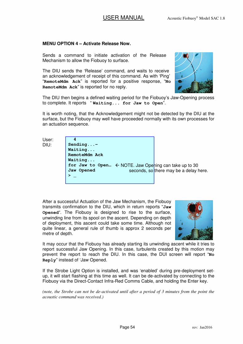
MENU OPTION 4 – Activate Release Now.
Sends a command to initiate activation of the Release Mechanism to allow the Fiobuoy to surface. The DIU sends the ‘Release’ command, and waits to receive an acknowledgement of receipt of this command. As with ‘Ping’ “RemoteMdm Ack” is reported for a positive response, “No
RemoteMdm Ack” is reported for no reply.
The DIU then begins a defined waiting period for the Fiobuoy’s Jaw-Opening process to complete. It reports “ Waiting... for Jaw to Open”.
It is worth noting, that the Acknowledgement might not be detected by the DIU at the surface, but the Fiobuoy may well have proceeded normally with its own processes for an actuation sequence. User: DIU:
After a successful Actuation of the Jaw Mechanism, the Fiobuoy transmits confirmation to the DIU, which in return reports “Jaw
Opened“. The Fiobuoy is designed to rise to the surface,
unwinding line from its spool on the ascent. Depending on depth of deployment, this ascent could take some time. Although not quite linear, a general rule of thumb is approx 2 seconds per metre of depth. It may occur that the Fiobuoy has already starting its unwinding ascent while it tries to report successful Jaw Opening. In this case, turbulents created by this motion may prevent the report to reach the DIU. In this case, the DUI screen will report “No
Reply” instead of ‘Jaw Opened.
If the Strobe Light Option is installed, and was ‘enabled’ during pre-deployment set-up, it will start flashing at this time as well. It can be de-activated by connecting to the Fiobuoy via the Direct-Contact Infra-Red Comms Cable, and holding the Enter key. (note, the Strobe can not be de-activated until after a period of 3 minutes from the point the
acoustic command was received.)
4
Sending...-
Waiting...
RemoteMdm Ack
Waiting...
for Jaw to Open…
Jaw Opened
> _
� NOTE. Jaw Opening can take up to 30 seconds, so there may be a delay here.
USER MANUAL Acoustic Fiobuoy Model SAC 1.8
Page 55 rev: Jan2016
18. Maintenance
1. The internal re-chargable battery should be replaced every 2 years.
• Remove the 8 front panel screws, and remove the front panel.
• Remove the 2 bolts of the Battery Bracket, and remove the battery, unclipping the 2 leads.
• Install an appropriate 6V 4AH equivalent (Fiomarine PN. 50-228-101) noting the polarity (Red-positive, Black-Negative)
• Re-secure the battery bracket, and replace the front panel and screws. 2. The Infra-Red optical connector should be kept clean and free from dirt etc. 3. The O-Ring seal in the lid should be inspected yearly.
4. Note, avoid fully flattening the battery (ie, by storing it switched on) as that will
damage the battery.
USER MANUAL Acoustic Fiobuoy Model SAC 1.8
Page 56 rev: Jan2016
19. Bench Testing – Acoustic Communications.
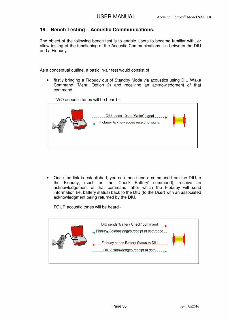
The object of the following bench test is to enable Users to become familiar with, or allow testing of the functioning of the Acoustic Communications link between the DIU and a Fiobuoy. As a conceptual outline, a basic in-air test would consist of
• firstly bringing a Fiobuoy out of Standby Mode via acoustics using DIU Wake Command (Menu Option 2) and receiving an acknowledgment of that command. TWO acoustic tones will be heard –
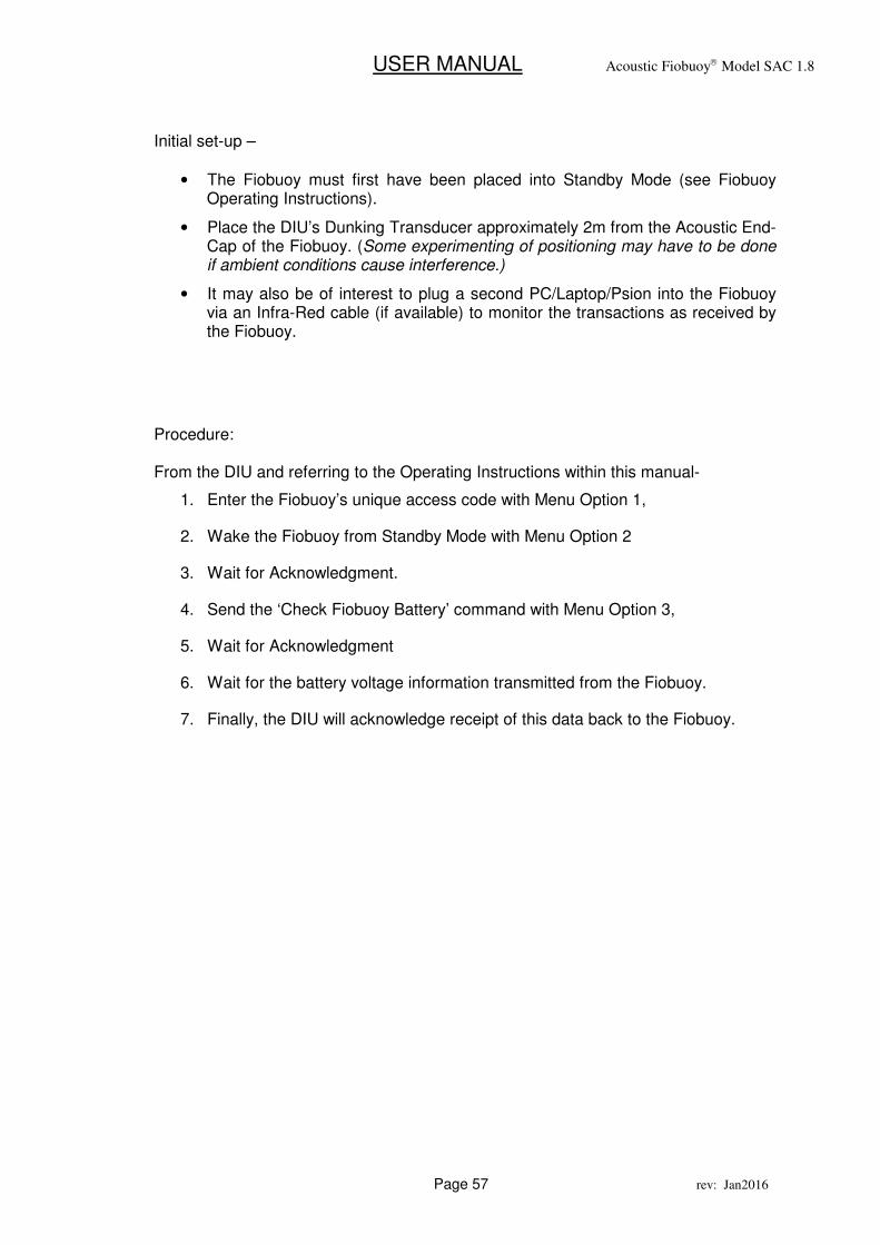
• Once the link is established, you can then send a command from the DIU to the Fiobuoy, (such as the ‘Check Battery’ command), receive an acknowledgement of that command, after which the Fiobuoy will send information (ie. battery status) back to the DIU (to the User) with an associated acknowledgment being returned by the DIU. FOUR acoustic tones will be heard -
DIU sends ‘Battery Check’ command
Fiobuoy Acknowledges receipt of command
Fiobuoy sends Battery Status to DIU
DIU Acknowledges receipt of data
DIU sends 10sec ‘Wake’ signal
Fiobuoy Acknowledges receipt of signal
USER MANUAL Acoustic Fiobuoy Model SAC 1.8
Page 57 rev: Jan2016
Initial set-up –
• The Fiobuoy must first have been placed into Standby Mode (see Fiobuoy Operating Instructions).
• Place the DIU’s Dunking Transducer approximately 2m from the Acoustic End-Cap of the Fiobuoy. (Some experimenting of positioning may have to be done if ambient conditions cause interference.)
• It may also be of interest to plug a second PC/Laptop/Psion into the Fiobuoy via an Infra-Red cable (if available) to monitor the transactions as received by the Fiobuoy.
Procedure: From the DIU and referring to the Operating Instructions within this manual-
1. Enter the Fiobuoy’s unique access code with Menu Option 1,
2. Wake the Fiobuoy from Standby Mode with Menu Option 2
3. Wait for Acknowledgment.
4. Send the ‘Check Fiobuoy Battery’ command with Menu Option 3,
5. Wait for Acknowledgment
6. Wait for the battery voltage information transmitted from the Fiobuoy.
7. Finally, the DIU will acknowledge receipt of this data back to the Fiobuoy.
USER MANUAL Acoustic Fiobuoy Model SAC 1.8
Page 58 rev: Jan2016
20. About Through-Water Acoustic Communications
Factors effecting reliable acoustic communications. While the Fiobuoy’s Acoustic Communications system employs advanced technology to overcome impediments to the acoustic signal path, it is important understand that acoustic waves by their nature, are readily influenced by various factors present in the environment in which the Fiobuoy is intended to operate. Some of these include;
• layers of differing water temperature
• layers of differing salinity or freshwater channels
• rough surface conditions or surf
• Marine animals and plants containing air cavities
• Marine animal noise
• collapsing air bubbles
• boat engine or other man-made equipment noise
• seabed topography
Should you encounter difficulty in establishing acoustic communications with a deployed Fiobuoy, there are several strategies available to improve reliability:
Try -
• positioning the surface dunking transducer at different depths
• moving it away from the boat’s engines or sonar transducer.
• moving away, toward or on a different bearing to the deployed Fiobuoy.
• moving the dunking transducer, so that it is stationary within its local body of moving water.
• The dunking transducer should not stream out from the vessel, but sit vertically in the water for best results.
USER MANUAL Acoustic Fiobuoy Model SAC 1.8
Page 59 rev: Jan2016
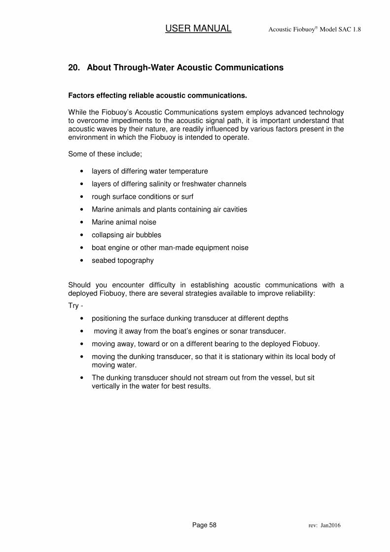
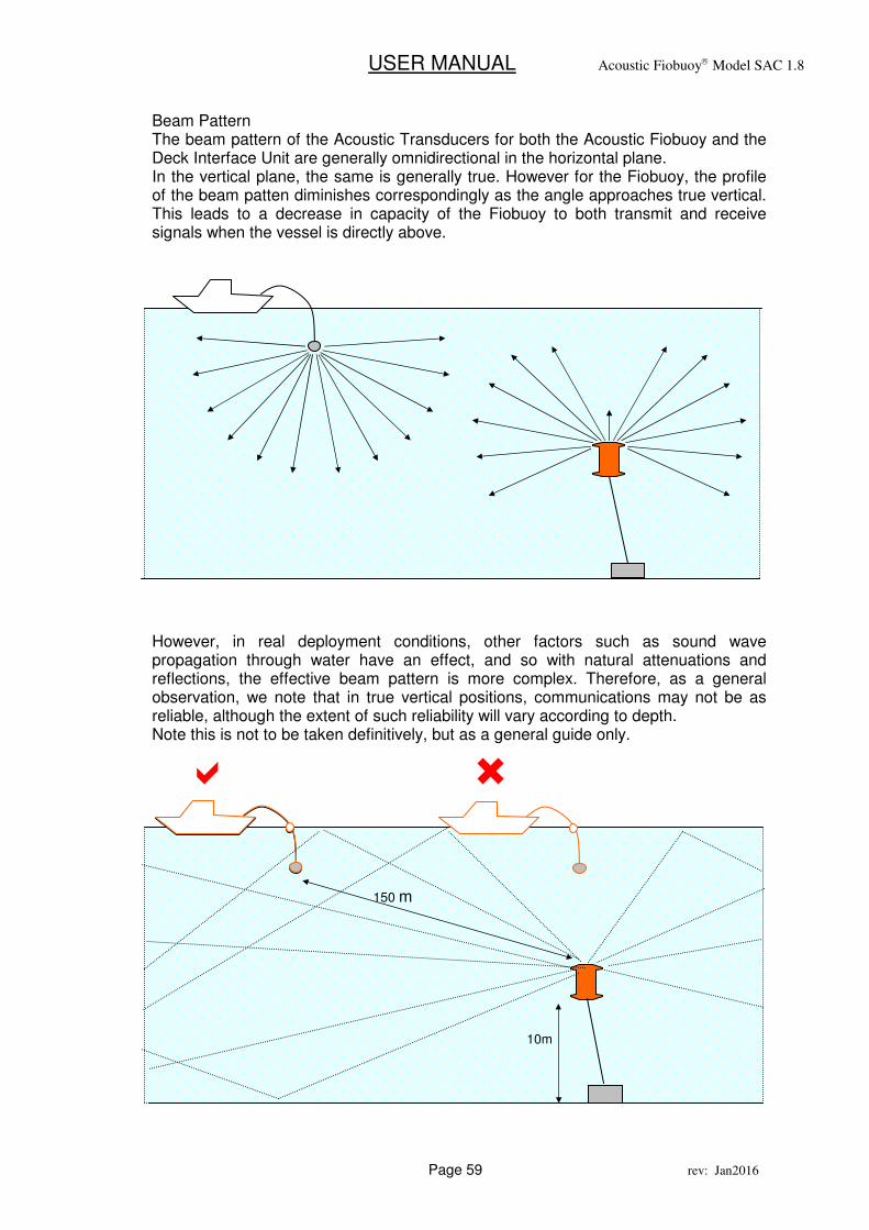
Beam Pattern The beam pattern of the Acoustic Transducers for both the Acoustic Fiobuoy and the Deck Interface Unit are generally omnidirectional in the horizontal plane. In the vertical plane, the same is generally true. However for the Fiobuoy, the profile of the beam patten diminishes correspondingly as the angle approaches true vertical. This leads to a decrease in capacity of the Fiobuoy to both transmit and receive signals when the vessel is directly above. However, in real deployment conditions, other factors such as sound wave propagation through water have an effect, and so with natural attenuations and reflections, the effective beam pattern is more complex. Therefore, as a general observation, we note that in true vertical positions, communications may not be as reliable, although the extent of such reliability will vary according to depth. Note this is not to be taken definitively, but as a general guide only.
150 m
10m
� �
USER MANUAL Acoustic Fiobuoy Model SAC 1.8
Page 60 rev: Jan2016
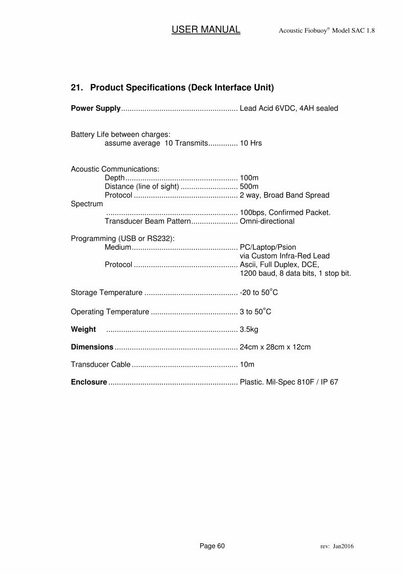
21. Product Specifications (Deck Interface Unit)
Power Supply ....................................................... Lead Acid 6VDC, 4AH sealed Battery Life between charges: assume average 10 Transmits .............. 10 Hrs Acoustic Communications: Depth ..................................................... 100m Distance (line of sight) ........................... 500m Protocol ................................................. 2 way, Broad Band Spread Spectrum .............................................................. 100bps, Confirmed Packet. Transducer Beam Pattern ...................... Omni-directional Programming (USB or RS232): Medium .................................................. PC/Laptop/Psion via Custom Infra-Red Lead Protocol ................................................. Ascii, Full Duplex, DCE, 1200 baud, 8 data bits, 1 stop bit.
Storage Temperature ............................................ -20 to 50°C
Operating Temperature ......................................... 3 to 50°C Weight .............................................................. 3.5kg Dimensions .......................................................... 24cm x 28cm x 12cm Transducer Cable .................................................. 10m Enclosure ............................................................. Plastic. Mil-Spec 810F / IP 67

USER MANUAL Acoustic Fiobuoy Model SAC 1.8
Page 61 rev: Jan2016
General
USER MANUAL Acoustic Fiobuoy Model SAC 1.8
Page 62 rev: Jan2016
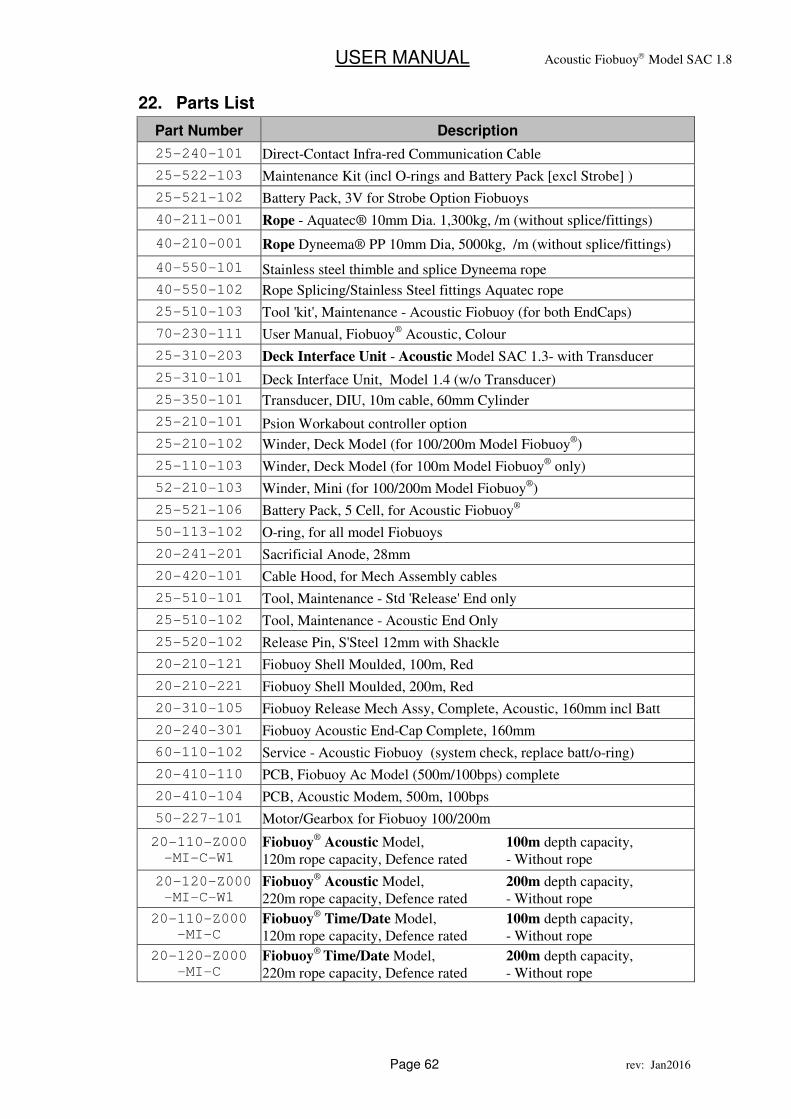
22. Parts List
Part Number Description
25-240-101 Direct-Contact Infra-red Communication Cable
25-522-103 Maintenance Kit (incl O-rings and Battery Pack [excl Strobe] )
25-521-102 Battery Pack, 3V for Strobe Option Fiobuoys
40-211-001 Rope - Aquatec® 10mm Dia. 1,300kg, /m (without splice/fittings)
40-210-001 Rope Dyneema® PP 10mm Dia, 5000kg, /m (without splice/fittings)
40-550-101 Stainless steel thimble and splice Dyneema rope
40-550-102 Rope Splicing/Stainless Steel fittings Aquatec rope
25-510-103 Tool 'kit', Maintenance - Acoustic Fiobuoy (for both EndCaps)
70-230-111 User Manual, Fiobuoy® Acoustic, Colour
25-310-203 Deck Interface Unit - Acoustic Model SAC 1.3- with Transducer
25-310-101 Deck Interface Unit, Model 1.4 (w/o Transducer)
25-350-101 Transducer, DIU, 10m cable, 60mm Cylinder
25-210-101 Psion Workabout controller option
25-210-102 Winder, Deck Model (for 100/200m Model Fiobuoy®)
25-110-103 Winder, Deck Model (for 100m Model Fiobuoy® only)
52-210-103 Winder, Mini (for 100/200m Model Fiobuoy®)
25-521-106 Battery Pack, 5 Cell, for Acoustic Fiobuoy®
50-113-102 O-ring, for all model Fiobuoys
20-241-201 Sacrificial Anode, 28mm
20-420-101 Cable Hood, for Mech Assembly cables
25-510-101 Tool, Maintenance - Std 'Release' End only
25-510-102 Tool, Maintenance - Acoustic End Only
25-520-102 Release Pin, S'Steel 12mm with Shackle
20-210-121 Fiobuoy Shell Moulded, 100m, Red
20-210-221 Fiobuoy Shell Moulded, 200m, Red
20-310-105 Fiobuoy Release Mech Assy, Complete, Acoustic, 160mm incl Batt
20-240-301 Fiobuoy Acoustic End-Cap Complete, 160mm
60-110-102 Service - Acoustic Fiobuoy (system check, replace batt/o-ring)
20-410-110 PCB, Fiobuoy Ac Model (500m/100bps) complete
20-410-104 PCB, Acoustic Modem, 500m, 100bps
50-227-101 Motor/Gearbox for Fiobuoy 100/200m
20-110-Z000
-MI-C-W1 Fiobuoy
® Acoustic Model, 100m depth capacity,
120m rope capacity, Defence rated - Without rope
20-120-Z000
-MI-C-W1 Fiobuoy
® Acoustic Model, 200m depth capacity,
220m rope capacity, Defence rated - Without rope
20-110-Z000
-MI-C Fiobuoy
® Time/Date Model, 100m depth capacity,
120m rope capacity, Defence rated - Without rope
20-120-Z000
-MI-C Fiobuoy
® Time/Date Model, 200m depth capacity,
220m rope capacity, Defence rated - Without rope
USER MANUAL Acoustic Fiobuoy Model SAC 1.8
Page 63 rev: Jan2016
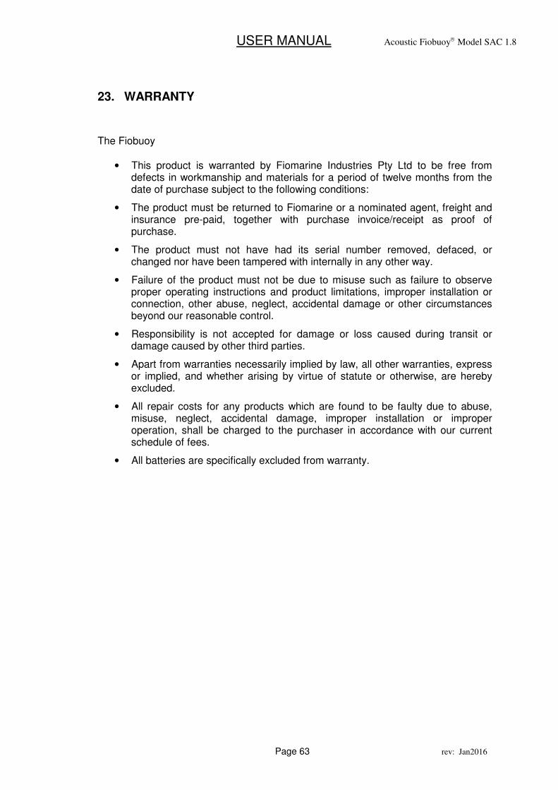
23. WARRANTY
The Fiobuoy
• This product is warranted by Fiomarine Industries Pty Ltd to be free from defects in workmanship and materials for a period of twelve months from the date of purchase subject to the following conditions:
• The product must be returned to Fiomarine or a nominated agent, freight and insurance pre-paid, together with purchase invoice/receipt as proof of purchase.
• The product must not have had its serial number removed, defaced, or changed nor have been tampered with internally in any other way.
• Failure of the product must not be due to misuse such as failure to observe proper operating instructions and product limitations, improper installation or connection, other abuse, neglect, accidental damage or other circumstances beyond our reasonable control.
• Responsibility is not accepted for damage or loss caused during transit or damage caused by other third parties.
• Apart from warranties necessarily implied by law, all other warranties, express or implied, and whether arising by virtue of statute or otherwise, are hereby excluded.
• All repair costs for any products which are found to be faulty due to abuse, misuse, neglect, accidental damage, improper installation or improper operation, shall be charged to the purchaser in accordance with our current schedule of fees.
• All batteries are specifically excluded from warranty.
USER MANUAL Acoustic Fiobuoy Model SAC 1.8
Page 64 rev: Jan2016
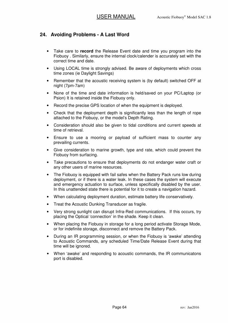
24. Avoiding Problems - A Last Word
• Take care to record the Release Event date and time you program into the Fiobuoy . Similarly, ensure the internal clock/calender is accurately set with the correct time and date.
• Using LOCAL time is strongly advised. Be aware of deployments which cross time zones (ie Daylight Savings)
• Remember that the acoustic receiving system is (by default) switched OFF at night (7pm-7am)
• None of the time and date information is held/saved on your PC/Laptop (or Psion) It is retained inside the Fiobuoy only.
• Record the precise GPS location of when the equipment is deployed.
• Check that the deployment depth is significantly less than the length of rope attached to the Fiobuoy, or the model’s Depth Rating.
• Consideration should also be given to tidal conditions and current speeds at time of retrieval.
• Ensure to use a mooring or payload of sufficient mass to counter any prevailing currents.
• Give consideration to marine growth, type and rate, which could prevent the Fiobuoy from surfacing.
• Take precautions to ensure that deployments do not endanger water craft or any other users of marine resources.
• The Fiobuoy is equipped with fail safes when the Battery Pack runs low during deployment, or if there is a water leak. In these cases the system will execute and emergency actuation to surface, unless specifically disabled by the user. In this unattended state there is potential for it to create a navigation hazard.
• When calculating deployment duration, estimate battery life conservatively.
• Treat the Acoustic Dunking Transducer as fragile.
• Very strong sunlight can disrupt Infra-Red communications. If this occurs, try placing the Optical ‘connection’ in the shade. Keep it clean.
• When placing the Fiobuoy in storage for a long period activate Storage Mode, or for indefinite storage, disconnect and remove the Battery Pack.
• During an IR programming session, or when the Fiobuoy is ‘awake’ attending to Acoustic Commands, any scheduled Time/Date Release Event during that time will be ignored.
• When ‘awake’ and responding to acoustic commands, the IR communicatons port is disabled.

USER MANUAL Acoustic Fiobuoy Model SAC 1.8
Page 65 rev: Jan2016
25. Contacting Us
For further assistance please contact either your local dealer or Fiomarine: Fiomarine Industries Pty Limited 30-38 Innovation Drive Glenorchy Tasmania 7010 Australia Phone +61 3 62726167 Fax +61 3 62726264
E-mail: [email protected]
Website: fiomarine.com Trademarks are the property of Fiomarine Investments Pty Limited.