An optimal method to design reinforced concrete lining of...
10
JME Journal of Mining & Environment, Vol. 9, No. 4, 2018, 829-837. DOI: 10.22044/jme.2018.6776.1500 An optimal method to design reinforced concrete lining of pressure tunnels E. Dadashi 1 , A. Noorzad 2* , K. Shahriar 3 and K. Goshtasbi 4 1. Department of Mining Engineering, Science, and Research Branch, Islamic Azad University, Tehran, Iran 2. Faculty of Civil, Water & Environmental Engineering, Shahid Beheshti University, Tehran, Iran 3. Department of Mining and Metallurgy Engineering, Amir Kabir University of Technology, Tehran, Iran 4. Department of Mining Engineering, Tarbiat Modares University, Tehran, Iran Received 11 February 2018; received in revised form 18 May 2018; accepted 3 June 2018 *Corresponding author: [email protected] (A. Noorzad). Abstract The utilization of the lining type in pressure tunnels is highly dependent on the geological and hydraulic conditions. There are two types of lining, namely concrete and steel lining but steel lining is one of the most expensive arrangements. To decrease the length of steel lining in these tunnels, the concrete lining, which prevents water seepage from the surrounding rock mass, is the appropriate alternative. In this work, a special attention is devoted to limit water losses in the concrete lining of pressure tunnel based on the critical reinforcing ratio in concrete lining. In order to evaluate the effect of internal water pressure on the permeability coefficient variation of the concrete lining and the surrounding rock mass, some simulations of reinforced concrete lining is implemented in the ABAQUS finite element software based on the coupled pore fluid-stress analysis. The results obtained indicate that although the critical reinforcing ratio has an important role in capturing the seepage flows and water losses, it is not sufficient to rely only on this parameter. However, among the various influential factors involved, a suitable arrangement of the reinforcement in the concrete lining should also be considered. Keywords: Pressure Tunnel, Reinforced Concrete Lining, Finite Element Model, ABAQUS Software, Seepage Control. 1. Introduction In a water pressure tunnel with concrete lining, part of the load will be transferred to the surrounding rock mass. If there is seepage flow through the lining, the excess pore water pressure will increase behind the lining [1]. Therefore, it is required to know the internal pressure in the tunnel design. Hence, it is also important to identify the permeability and deformation characteristics of the rock mass under the condition of high water head to estimate the seepage and stability of pressure tunnels. As mentioned above, the hydro-mechanical interaction analysis for the pressure tunnel and surrounding rock mass is important for two reasons. Firstly, the hydraulic characteristics of seepage phenomenon such as the efficiency of the concrete lining, rock mass, grouted zone, and seepage flow rate can be evaluated. Secondly, the effect of seepage force on the stress–deformation behavior of the concrete lining and the surrounding rock mass can be examined [2]. In the recent years, the concrete lining design of water pressure tunnels has been developed considerably. Seeber [3] has presented a diagram to evaluate the bearing capacity of pressure tunnel lining pre-stressed by grouting as long as in which the rock masses behave as an elastic material and the lining is impervious. Among the analytical methods, Schleiss [4-6] and Fernandez [7] have presented a framework to take into account the hydro-mechanical interaction in the reinforced concrete lining design of pressure tunnels, which seems to be a more wide-ranging solution. However, in those approaches, the elastic behavior of the reinforced concrete lining and the surrounding rock mass under internal water
Transcript of An optimal method to design reinforced concrete lining of...

JME Journal of Mining & Environment, Vol. 9, No. 4, 2018, 829-837.
DOI: 10.22044/jme.2018.6776.1500
An optimal method to design reinforced concrete lining of pressure tunnels
E. Dadashi
1, A. Noorzad
2*, K. Shahriar
3 and K. Goshtasbi
4
1. Department of Mining Engineering, Science, and Research Branch, Islamic Azad University, Tehran, Iran
2. Faculty of Civil, Water & Environmental Engineering, Shahid Beheshti University, Tehran, Iran
3. Department of Mining and Metallurgy Engineering, Amir Kabir University of Technology, Tehran, Iran
4. Department of Mining Engineering, Tarbiat Modares University, Tehran, Iran
Received 11 February 2018; received in revised form 18 May 2018; accepted 3 June 2018
*Corresponding author: [email protected] (A. Noorzad).
Abstract
The utilization of the lining type in pressure tunnels is highly dependent on the geological and hydraulic
conditions. There are two types of lining, namely concrete and steel lining but steel lining is one of the most
expensive arrangements. To decrease the length of steel lining in these tunnels, the concrete lining, which
prevents water seepage from the surrounding rock mass, is the appropriate alternative. In this work, a special
attention is devoted to limit water losses in the concrete lining of pressure tunnel based on the critical
reinforcing ratio in concrete lining. In order to evaluate the effect of internal water pressure on the
permeability coefficient variation of the concrete lining and the surrounding rock mass, some simulations of
reinforced concrete lining is implemented in the ABAQUS finite element software based on the coupled pore
fluid-stress analysis. The results obtained indicate that although the critical reinforcing ratio has an important
role in capturing the seepage flows and water losses, it is not sufficient to rely only on this parameter.
However, among the various influential factors involved, a suitable arrangement of the reinforcement in the
concrete lining should also be considered.
Keywords: Pressure Tunnel, Reinforced Concrete Lining, Finite Element Model, ABAQUS Software, Seepage
Control.
1. Introduction
In a water pressure tunnel with concrete lining,
part of the load will be transferred to the
surrounding rock mass. If there is seepage flow
through the lining, the excess pore water pressure
will increase behind the lining [1]. Therefore, it is
required to know the internal pressure in the
tunnel design. Hence, it is also important to
identify the permeability and deformation
characteristics of the rock mass under the
condition of high water head to estimate the
seepage and stability of pressure tunnels. As
mentioned above, the hydro-mechanical
interaction analysis for the pressure tunnel and
surrounding rock mass is important for two
reasons. Firstly, the hydraulic characteristics of
seepage phenomenon such as the efficiency of the
concrete lining, rock mass, grouted zone, and
seepage flow rate can be evaluated. Secondly, the
effect of seepage force on the stress–deformation
behavior of the concrete lining and the
surrounding rock mass can be examined [2].
In the recent years, the concrete lining design of
water pressure tunnels has been developed
considerably. Seeber [3] has presented a diagram
to evaluate the bearing capacity of pressure tunnel
lining pre-stressed by grouting as long as in which
the rock masses behave as an elastic material and
the lining is impervious. Among the analytical
methods, Schleiss [4-6] and Fernandez [7] have
presented a framework to take into account the
hydro-mechanical interaction in the reinforced
concrete lining design of pressure tunnels, which
seems to be a more wide-ranging solution.
However, in those approaches, the elastic behavior
of the reinforced concrete lining and the
surrounding rock mass under internal water
Dadashi et al./ Journal of Mining & Environment, Vol. 9, No. 4, 2018
830
pressure are considered. Following the thick-
walled cylindrical theory, Su and Li [8] have
carried out a design approach of pressure tunnel
with reinforcement concrete lining under
consolidation grouting. Their results showed that
the method of consolidation grouting could
sharply decrease water seepage from the tunnel. In
addition, the quality of consolidation grouting is
more essential than the depth of grouting to
control water leakage. Simanjuntak et al. [9] have
developed the applicability of the finite element
model to predict the hydro-mechanical behavior
and bearing capacity of pre-stressed concrete-
lined pressure tunnels subjected to a 2D plane
strain condition. Parvathi et al. [10] have studied
the effect of the size of the tunnel on the stress
distribution in the concrete lining of pressure
tunnels. Olumide [11] has simulated the coupling
of stress, seepage, and lining crack propagation in
the design of plain concrete lining of pressure
tunnels using the Plaxis 2D elasto-plastic finite
element program. The results obtained indicate
that if the rock mass is originally tight or pre-
stressed, the seepage from the tunnel will increase
the external pressure. The external pressure
decreases the gradient between the internal and
external water pressure, which leads to a drop in
the seepage flow of the tunnel. Simanjuntak et al.
[12] have also determined the bearing capacity of
concrete-lined pressure tunnels based on the
superposition principle in non-uniform in-situ
stress conditions. The results obtained
demonstrate the different distributions of crack
opening locations in the final lining, which is
useful for taking measures regarding the tunnel
stability. In order to simulate the boundary
condition between the reinforced concrete lining
and the surrounding rock and to compute the
secondary permeability of cracked lining, Zhou et
al. [13] have developed a water-filled joint (WFJ)
element. They showed that the new equivalent
coupling method reflected the actual stress level
of reinforced concrete tunnel with a high internal
water pressure.
In the present work, the variations in hoop stress
with radial distance and shear stress along the
concrete rock interface have been computed. In
addition, the total amount of tension and
compression stresses in the lining is applied in its
design. Since the effect of discontinuities is
assumed by changing the material behavior, the
concrete lining and the surrounding rock mass are
considered as equivalent continuum media, and a
three-dimensional finite element method (3D
FEM) is employed to determine the seepage flow.
The proposed model also involves the effect of
stress-dependent permeability of reinforced
concrete lining and surrounding rock mass using a
coupled pore fluid-stress analysis. It is worthy to
note that in the previous models, it has not been
considered. Based on the literature, the
hydro-mechanical interaction of the previous
works [6, 8, 11, 13] was based upon the indirect-
coupled method. However, a change in internal
water pressure incorporates changes in the volume
of the media; therefore, the direct hydro-
mechanical coupling should be taken in account.
To conclude, this proposed method solves the
equilibrium equations governing the pressure
tunnel problems for the first time.
2. Effect of hydro-mechanical interaction on
concrete cracking and seepage flow
The hydro-mechanical interaction is a complex
process when the inner water is discharged
through the cracked lining and the porous rock
mass [14]. Before the lining cracking, the
permeability coefficient of reinforced concrete
lining is very small, and the pore water pressure in
the lining is set to have a logarithmic distribution
[4]. When the internal water pressure increases,
the concrete lining will crack as soon as the
tensile stress in the concrete lining exceeds its
existing tensile strength [13]. After the crack
develops and propagates, the external water
pressure on the lining decreases the seepage flow
from the tunnel. Finally, based on the continuity
of flow, the water flow in the lining and the
surrounding rock mass will tend to reach an
equilibrium state [15].
2.1. Modification of permeability coefficient after
media cracking
When cracks develop in the concrete lining at a
high water pressure, the properties of the concrete
lining change, and as a result, the stress dependent
permeability of the lining and the surrounding
rock mass in pressure tunnels should be
considered in the computation [15].
The permeability coefficient controls the rate of
seepage flow in the porous and fractured media.
Although permeability represents an original
property of the porous media, it can be modified
when subjected to the stress variations [15].
Instead of changing aperture, the change in the
void space or volume is the typical consequence
that results in changing the permeability
coefficient [16]. The permeability coefficient
variation of the rock mass can be expressed as:
Dadashi et al./ Journal of Mining & Environment, Vol. 9, No. 4, 2018
831
11 (1/3)3 30k k [( )(1 ) ( )(1 ) ]v v00 0
(1)
where 0k is the initial permeability coefficient
(m/s), v is the volumetric strain due to the
application of the internal water pressure
corresponding to the evolution of plasticity, and
0 is the initial void ratio [17, 18]. The
permeability coefficient variation of concrete
lining is [19]:
1.64k k .exp[11.3D]0
(2)
where k and k0 are the current and the initial
material permeability, respectively, and D is the
damage variable of the concrete lining. Since the
response of the model is considered only in
tension, the concrete damage extent is described
by the following equation [20]:
tD D 1t plE ( )t t0
(3)
where 0E is the initial elastic stiffness of the
concrete lining (MPa), t is the tensile stress
(MPa), pl
t is the tensile equivalent plastic strain,
and t is the total strain.
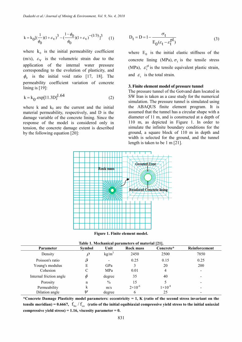
3. Finite element model of pressure tunnel
The pressure tunnel of the Gotvand dam located in
SW Iran is taken as a case study for the numerical
simulation. The pressure tunnel is simulated using
the ABAQUS finite element program. It is
assumed that the tunnel has a circular shape with a
diameter of 11 m, and is constructed at a depth of
110 m, as depicted in Figure 1. In order to
simulate the infinite boundary conditions for the
ground, a square block of 110 m in depth and
width is selected for the ground, and the tunnel
length is taken to be 1 m [21].
Figure 1. Finite element model.
Table 1. Mechanical parameters of material [21].
Parameter Symbol Unit Rock mass Concrete* Reinforcement
Density kg/m3 2450 2500 7850
Poisson's ratio - 0.25 0.15 0.25
Young's modulus E GPa 3 20 200
Cohesion C MPa 0.01 4 -
Internal friction angle degree 35 40 -
Porosity n % 15 5 -
Permeability
Dilation angle
k
m/s
degree
2×10⁻⁶
6
1×10⁻⁸
25
-
-
*Concrete Damage Plasticity model parameters: eccentricity = 1, K (ratio of the second stress invariant on the
tensile meridian) = 0.6667, bo cof / f (ratio of the initial equibiaxial compressive yield stress to the initial uniaxial
compressive yield stress) = 1.16, viscosity parameter = 0.
Dadashi et al./ Journal of Mining & Environment, Vol. 9, No. 4, 2018
832
The rock mass is assumed to behave as elastic-
perfectly plastic Mohr-Coulomb. In order to
demonstrate the response of the reinforced
concrete lining, the concrete damaged plasticity
model along with the elasto-plastic behavior is
considered to simulate the behavior of the
concrete and reinforcement [15]. The evolution of
the yield surface of the concrete lining is also
controlled by tensile and compressive equivalent
plastic strains, correspondingly [22]. The material
properties of the rock mass, reinforcement, and
concrete lining are given in Table 1.
Since the pressure tunnels have been excavated
using the conventional drill and blast technique, in
this work, the excavation steps are simulated by
the stiffness reduction method. It should be noted
that the reinforced concrete lining may be
separated from the temporary support and/or the
surrounding rock mass under the high internal
pressure [15]. In order to simplify the hydro-
mechanical interaction analysis, the concrete
lining and the surrounding rock mass are assumed
to be well-secured. In addition, the treatment of
temporary support is considered as a part of
concrete lining, and the thickness of the final
lining is suggested to be 40 cm. The quality of
contact surface between the reinforcement and
concrete has a significant impact on the results of
the analyses. If the contact area is reduced due to
the large deformations, the effect of the
discontinuity should be accounted in the analysis.
The embedded element is used for making a full
contact between the reinforcement and the
concrete [15].
Based on the structural tunnel design and to
control the compression and tension in the
concrete lining [23], the reinforcement radius is
taken at the two positions rs = 5.15 m and 5.45 m,
respectively. The 8-node trilinear displacement
and pore pressure elements (C3D8P) are chosen
for rock mass and concrete lining, while the 2-
node linear truss elements (T3D2) are selected for
reinforcement. In pressure tunnels, the internal
water pressure at the inner surface of the lining is
gradually applied to reach the maximum internal
water pressure and steady state condition. For the
phase of the internal water pressure loading, two
boundaries are considered. The first boundary at
the inner surface of the reinforced concrete lining
is imposed by internal water pressure. The second
boundary is imposed at the outside of the model
domain by the groundwater level. Since the tunnel
is assumed to be excavated under drained
conditions, external water pressure at the outside
of the model domain is equal to zero [15].
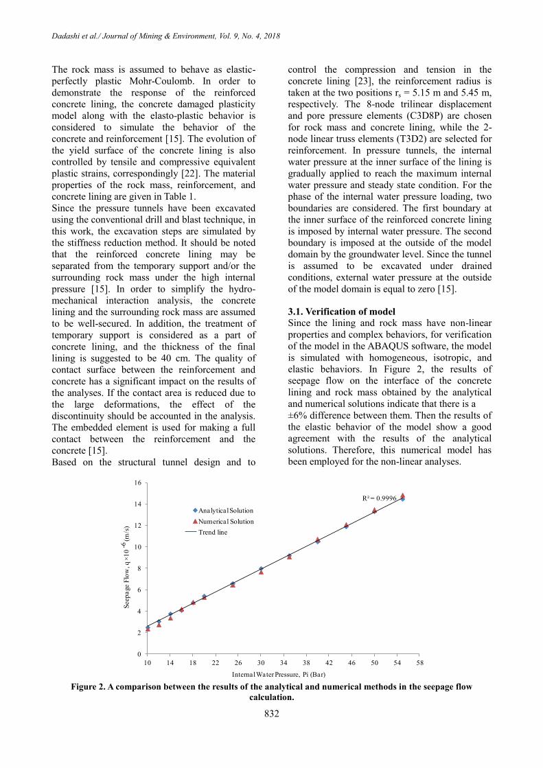
3.1. Verification of model
Since the lining and rock mass have non-linear
properties and complex behaviors, for verification
of the model in the ABAQUS software, the model
is simulated with homogeneous, isotropic, and
elastic behaviors. In Figure 2, the results of
seepage flow on the interface of the concrete
lining and rock mass obtained by the analytical
and numerical solutions indicate that there is a
±6% difference between them. Then the results of
the elastic behavior of the model show a good
agreement with the results of the analytical
solutions. Therefore, this numerical model has
been employed for the non-linear analyses.
Figure 2. A comparison between the results of the analytical and numerical methods in the seepage flow
calculation.
R² = 0.9996
0
2
4
6
8
10
12
14
16
10 14 18 22 26 30 34 38 42 46 50 54 58
Seep
age F
low
, q
10
(
m/s
)
Internal Water Pressure, Pi (Bar)
Analytical Solution
Numerical Solution
-6
Trend line

Dadashi et al./ Journal of Mining & Environment, Vol. 9, No. 4, 2018
833
4. Results and discussion
4.1. Tunnel stability control before applying
internal water pressure
In order to evaluate the pressure tunnel stability
before applying the internal water pressure, it is
required to compare the displacement results from
the numerical model with the allowable
displacements around the underground space [24].
To achieve the stability, it is necessary that the
displacements obtained from the numerical model
are less than the permissible displacement from
Equation (4) [25]. This equation expresses the
critical strain in the confined pressure conditions
around the tunnel as a function of the zone
deformation modulus [24].
clog 0.25logE 1.22 (4)
where E is the rock deformation modulus (kg/cm2)
and c is the critical strain percent. By
determining the permissible strain, the
displacement will be calculated. The permissible
displacement is obtained as follows [24]:
cc
u
a (5)
where cu is the displacement on the tunnel roof
and a is the tunnel radius (Sakurai 1997). Thus the
critical strain is equal to 4.57 × 10⁻³
and the
displacement has been calculated to be 25 mm.
The displacement recorded in the roof of the
tunnel is investigated for the lining thicknesses of
30 cm, 35 cm, and 40 cm. As shown in Figure 3,
the displacement in the roof of the tunnel is about
7 mm for the thickness of 40 cm. Thus the safety
of the tunnel is not at risk before applying internal
water pressure.
Figure 3. Displacement in the roof of tunnel before the applied internal water pressure.
4.2. Seepage control after applying internal
water pressure
During the water filling process of the tunnel,
when the tensile stress exceeds the tensile strength
at the intrados of concrete lining, the cracks occur
in the concrete lining under the hydro-mechanical
interaction. The equivalent plastic strain in tension
is referred to as the damaged state and the crack
development in the concrete lining under the high
internal water pressure. The development of the
cracks due to the damaged states in the reinforced
concrete lining is demonstrated in Figure 4. In
these conditions, the stress in the steel bars
increases in the locations of lining due to the
internal water pressure, as shown in Figure 5.
Figure 4. Development of cracks in the concrete lining under internal water pressure.

Dadashi et al./ Journal of Mining & Environment, Vol. 9, No. 4, 2018
834
Figure 5. Increasing the stress on the steel bars under internal water pressure in the locations of lining.
4.2.1. Proposing reinforced concrete lining
Since the stresses in the suitable arrangement of
reinforcement have to be lower than the allowable
stress, and the allowable stress is smaller than the
yield stress ( f 400MPay ), there is no difference
between the elastic and elastic-perfectly plastic
behaviors of the reinforcement. Therefore, the
stress-strain relationship of the reinforcement in
the model is expressed as E .
With respect to the thickness of the concrete lining,
the maximum tensile stress in the concrete lining
from the numerical method has been obtained to
be about 1.46 MPa. The maximum tensile stress at
the point of cracking is obtained from the
following equation:
.6
t t cF A 1.46 10 0.4 1 584000(N) (6)
where tF is the maximum force in the concrete
lining (N), t is the maximum critical tensile
stress in the concrete lining (N/m2), and cA is
the cross-section area of the concrete lining (m2).
This maximum force in the concrete lining will be
the criterion for the reinforcement design in the
concrete lining. In the allowable stress design
method, the stress induced at the steel bars should
be less than the allowable stress ( yf 400MPa ),
and thus the percentage of the reinforcement in
the concrete lining can be calculated using:
2s t y
6A F / 0.5f 584000/ (200 10 ) 0.00292(m )
(7)
where sA is the cross-section area of steel bars
(m2) and yf is the stress induced at the steel bars
in the allowable stress design method (N/m2).
The design of the reinforcement in the concrete
lining of the pressure tunnels is governed by
limiting stress in the steel bars, limiting width of
cracks in the concrete lining, and limiting water
losses from the tunnel [5]. To meet all the
requirements, the spacing and the diameter of the
steel bars in the concrete lining should be
optimized for up to a particular level of internal
water pressure.
Damage models of the concrete lining are capable
of representing crack initiation and crack
propagation within a continuum framework. In
principle, these models do not provide crack
openings, and the maximum crack width is not
calculated. In the durability analyses of
reinforcement concrete lining, however, the
transfer properties are the key issues controlled by
crack propagation and crack opening.
Stresses at different levels of internal water
pressure for the cases of the same steel ratio are
compared in Figure 6. As a result, the stress in the
reinforcement of the Φ 16 mm @ 20 cm remains
at a lower amount under 80 bars internal water
pressure.
Based on Figure 7, the water losses from the
tunnel for the two cases of steel quantities of Φ
16 mm @ 20 cm and Φ 20 mm @ 30 cm in the
concrete lining are compared under 15 bars
internal water pressure. Since the water losses of
the tunnel for the two cases of steel bars are about
1.5 × 10⁻⁶
m3/s and 2.1 × 10
-6 m
3/s, respectively,
the water loss from the tunnel with the net of Φ
20 mm @ 30 cm increases about 40%. Thus the
distribution of the steel bars is not appropriate,
and therefore, the net of Φ 16 mm @ 20 cm is the
appropriate arrangement of reinforcement that
contributes to minimize water losses from the
tunnel.
The development of the cracks in the reinforced
concrete lining under the internal water pressure
of 1.5 MPa is given in Figure 8. The state of
the Φ16 mm @ 20 cm contributes to distribute
the cracks on the reinforced concrete lining in the
form of micro-cracks. In this state, when the
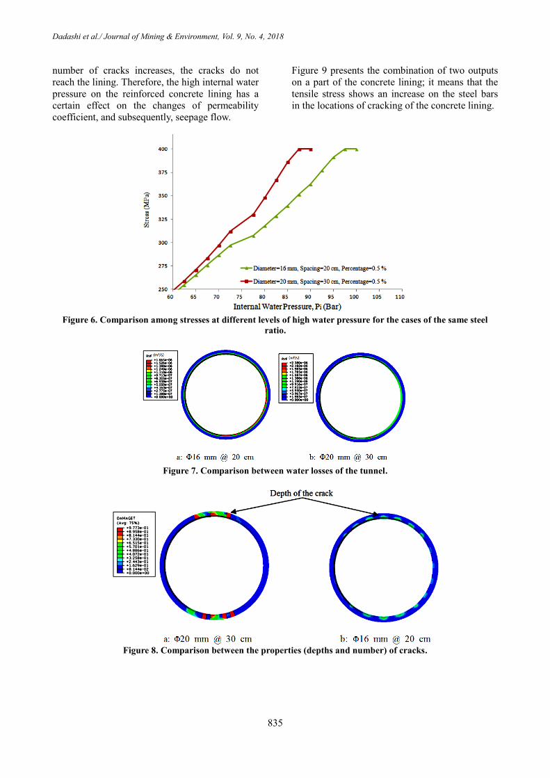
Dadashi et al./ Journal of Mining & Environment, Vol. 9, No. 4, 2018
835
number of cracks increases, the cracks do not
reach the lining. Therefore, the high internal water
pressure on the reinforced concrete lining has a
certain effect on the changes of permeability
coefficient, and subsequently, seepage flow.
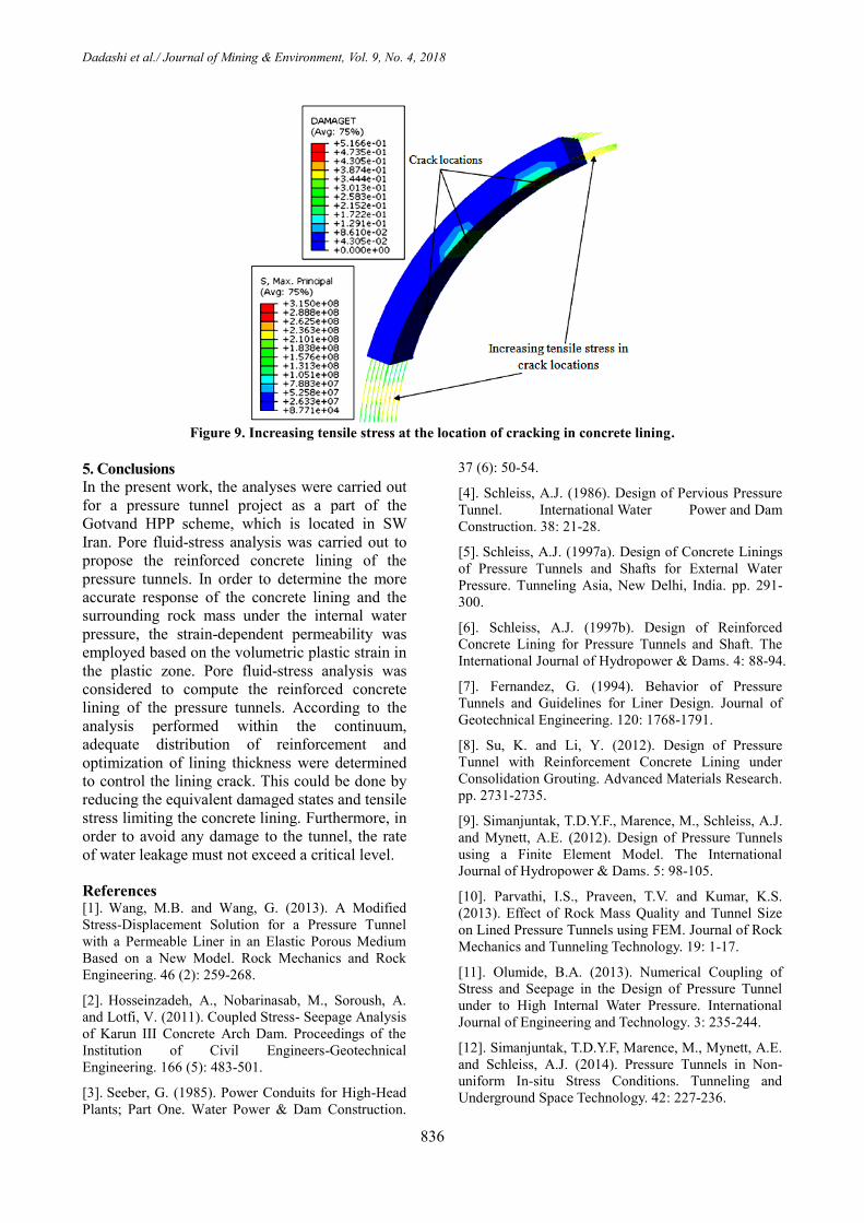
Figure 9 presents the combination of two outputs
on a part of the concrete lining; it means that the
tensile stress shows an increase on the steel bars
in the locations of cracking of the concrete lining.
Figure 6. Comparison among stresses at different levels of high water pressure for the cases of the same steel
ratio.
Figure 7. Comparison between water losses of the tunnel.
Figure 8. Comparison between the properties (depths and number) of cracks.
Dadashi et al./ Journal of Mining & Environment, Vol. 9, No. 4, 2018
836
Figure 9. Increasing tensile stress at the location of cracking in concrete lining.
5. Conclusions
In the present work, the analyses were carried out
for a pressure tunnel project as a part of the
Gotvand HPP scheme, which is located in SW
Iran. Pore fluid-stress analysis was carried out to
propose the reinforced concrete lining of the
pressure tunnels. In order to determine the more
accurate response of the concrete lining and the
surrounding rock mass under the internal water
pressure, the strain-dependent permeability was
employed based on the volumetric plastic strain in
the plastic zone. Pore fluid-stress analysis was
considered to compute the reinforced concrete
lining of the pressure tunnels. According to the
analysis performed within the continuum,
adequate distribution of reinforcement and
optimization of lining thickness were determined
to control the lining crack. This could be done by
reducing the equivalent damaged states and tensile
stress limiting the concrete lining. Furthermore, in
order to avoid any damage to the tunnel, the rate
of water leakage must not exceed a critical level.
References [1]. Wang, M.B. and Wang, G. (2013). A Modified
Stress-Displacement Solution for a Pressure Tunnel
with a Permeable Liner in an Elastic Porous Medium
Based on a New Model. Rock Mechanics and Rock
Engineering. 46 (2): 259-268.
[2]. Hosseinzadeh, A., Nobarinasab, M., Soroush, A.
and Lotfi, V. (2011). Coupled Stress- Seepage Analysis
of Karun III Concrete Arch Dam. Proceedings of the
Institution of Civil Engineers-Geotechnical
Engineering. 166 (5): 483-501.
[3]. Seeber, G. (1985). Power Conduits for High-Head
Plants; Part One. Water Power & Dam Construction.
37 (6): 50-54.
[4]. Schleiss, A.J. (1986). Design of Pervious Pressure
Tunnel. International Water Power and Dam
Construction. 38: 21-28.
[5]. Schleiss, A.J. (1997a). Design of Concrete Linings
of Pressure Tunnels and Shafts for External Water
Pressure. Tunneling Asia, New Delhi, India. pp. 291-
300.
[6]. Schleiss, A.J. (1997b). Design of Reinforced
Concrete Lining for Pressure Tunnels and Shaft. The
International Journal of Hydropower & Dams. 4: 88-94.
[7]. Fernandez, G. (1994). Behavior of Pressure
Tunnels and Guidelines for Liner Design. Journal of
Geotechnical Engineering. 120: 1768-1791.
[8]. Su, K. and Li, Y. (2012). Design of Pressure
Tunnel with Reinforcement Concrete Lining under
Consolidation Grouting. Advanced Materials Research.
pp. 2731-2735.
[9]. Simanjuntak, T.D.Y.F., Marence, M., Schleiss, A.J.
and Mynett, A.E. (2012). Design of Pressure Tunnels
using a Finite Element Model. The International
Journal of Hydropower & Dams. 5: 98-105.
[10]. Parvathi, I.S., Praveen, T.V. and Kumar, K.S.
(2013). Effect of Rock Mass Quality and Tunnel Size
on Lined Pressure Tunnels using FEM. Journal of Rock
Mechanics and Tunneling Technology. 19: 1-17.
[11]. Olumide, B.A. (2013). Numerical Coupling of
Stress and Seepage in the Design of Pressure Tunnel
under to High Internal Water Pressure. International
Journal of Engineering and Technology. 3: 235-244.
[12]. Simanjuntak, T.D.Y.F, Marence, M., Mynett, A.E.
and Schleiss, A.J. (2014). Pressure Tunnels in Non-
uniform In-situ Stress Conditions. Tunneling and
Underground Space Technology. 42: 227-236.

Dadashi et al./ Journal of Mining & Environment, Vol. 9, No. 4, 2018
837
[13]. Zhou, Y., Su, K. and Wu, H. (2015). Hydro-
Mechanical Interaction Analysis of High Pressure
Hydraulic Tunnel. Tunneling and Underground Space
Technology. 47: 28-34.
[14]. Bian, K., Xiao, M. and Chen, J. (2009). Study on
Coupled Seepage and Stress Fields in the Concrete
Lining of the Underground Pipe with High Water
Pressure. Tunneling and Underground Space
Technology. 24: 287-295.
[15]. Dadashi, E., Noorzad, A., Shahriar, K. and
Goshtasbi, K. (2017). Hydro-mechanical interaction
analysis of reinforced concrete lining in pressure
tunnels. Tunnelling and Underground Space
Technology. 69: 125-132.
[16]. Bai, M., Meng, F., Elsworth, D., Zaman, M. and
Roegiers, J. (1997). Numerical Modeling of Stress-
Dependent Permeability. International Journal Rock
Mechanics and Mining Science. 34: 2-10.
[17]. Jun, L.J., Bin, Y.X. and Zhou, Z.J. (2013).
Numerical Simulation of Geo-stress and Pore Pressure
Evolution around Oil or Water Well under Different
Injection-Production Ratio. Mathematical Problems in
Engineering. pp. 1-10.
[18]. Ying, C., Youzhi, W. and Yu, Z.Q. (2014).
Coupled Seepage Elasto-Plastic Damage Analysis of
Saturated Porous Media and its Application to Water
Conveyance Tunnel. Tunneling and Underground
Space Technology. 44: 80-87.
[19]. Cabot, P.G., Dufour, F. and Choinska, M. (2009).
Permeability due to the Increase of Damage in
Concrete: From Diffuse to Localized Damage
Distributions. Journal of Engineering Mechanics. 135:
1022-1028.
[20]. Simulia. (2011). ABAQUS Theory Manual.
Dassault Systèmes, Providence, RI, USA.
[21]. Mahab Ghods Consulting Engineering Company.
(2008). Report of Introduction, Implemented Studies,
and Execution Characteristics of Gotvand HPP Scheme.
Tehran, Iran. pp. 6-38.
[22]. Ahmed, A. (2014). Modeling of a Reinforced
Concrete Beam subjected to Impact Vibration using
ABAQUS. International Journal of Civil and Structural
Engineering. 4: 227-236.
[23]. ITA Working Group. (1988). Guidelines for the
Design of Tunnels. Tunneling and Underground Space
Technology. 3: 237-249.
[24]. Dadashi, E., Ahangari, K., Noorzad, A. and Arab,
A. (2012). Support System Suggestion Based on Back
Analysis Results Case Study: Babolak Water
Conveyance Tunnel. Arabian Journal of Geosciences. 5:
1297-1306.
[25]. Sakurai, S. (1997). Lessons Learned From Field
Measurements in Tunneling. Tunnelling and
Underground Space Technology. 12 (4): 453-460.
7931م، سال چهاردوره نهم، شماره زیست، پژوهشی معدن و محیط -و همکاران/ نشریه علمی داداشی
فشارتحتهایبرایطراحیپوششبتنیمسلحدرتونلایروشبهینهارائه
4وکامرانگشتاسبی،3کورششهریار*،2علینورزاد1احسانداداشی
1-آزاددانشگاه،تحقیقاتوعلومواحد،معدنمهندسیایرانگروه،تهران،اسالمی
2-دانشکدهوآب،عمرانمحیطمهندسیایرانزیست،تهرانبهشتیشهیددانشگاه،
3-صنعتیدانشگاه،متالورژیومعدنمهندسیایرانریرکبیامدانشکده،
4-ایران،مدرستربیتدانشگاه،مهندسیوفنیدانشکده،معدنمهندسیبخش
9/6/2172، پذیرش 77/2/2172ارسال
[email protected]* نویسنده مسئول مکاتبات:
چکیده:
دو نوع پوشش بتنی و فوالدی وجوود دارد اموا پوشوش فووالدی شناسی و هیدرولیکی است. های فشار بسیار وابسته به شرایط زمین استفاده از نوع پوشش در تونل
عنووان های بتنی به ها، پوشش شده در این تونل برای کاهش طول پوشش فوالدی پیشنهاد فشار است.های تحت های پیشنهادی برای تونل ترین طرح یکی از گران
فشوار بور اسوا های سنگی اطراف به داخل تونل گزینه مناسبی است. در این پژوهش، کاهش هدرروی آب از پوشش بتنی تونل تحت مانعی برای نفوذ آب از توده
تووده منظور بررسی تأثیر فشار آب داخلی بر ضریب نفوذپذیری متغیور پوشوش بتنوی و در دستور کار قرار گرفته است. لذا به نسبت تسلیح بحرانی در پوشش بتن
دسوت بوه نتوای فشارمنفذی اجرا شده است. -تنش توأمانبر اسا تحلیل ABAQUS افزار المان محدود بتنی مسلح در نرم سازی پوشش اطراف، شبیه سنگ
دهد که هر چند نسبت تسلیح بحرانی پوشش نقش مهمی در کاهش جریان نشت و هدرروی آب از پوشش بتنی دارد، لوذا تنهوا ایون پوارامتر نتوای آمده نشان می
پوشش بتنی نیز مورد توجه قرار گیرد. های کننده تا در میان عوامل مختلف تأثیرگذار، آرایش مناسب تقویت است الزمبنابراین کند نمی نیتأممطلوب را
، کنترل نشت.ABAQUSافزار فشار، پوشش بتنی مسلح، مدل المان محدود، نرم تونل تحت کلماتکلیدی: