An Experimental Study of the Influence of the Herschel ... · Herschel-QuincleTube Length on Noise...
16
University Bulletin – ISSUE No.19- Vol. (1) – March - 2017. - 67 - An Experimental Study of the Influence of the Herschel-QuincleTube Length on Noise Attenuation Dr. Mohamed K. Al-Taleb, Dr. Salem A. Farhat, Dr. Radwan N. Sharif Dept. of Mechanical and Industrial Engineering- Faculty of Engineering Tripoli University Abstract: The present study addresses experimental results to investigate the effect of the Herschel-Quincke (HQ) tube length on the reduction of noise. In this paper the detailed experiment is carried out in an acoustically cylindrical duct with and without HQ induced by a loudspeaker at various frequencies. Microphone system has been used to measure the net acoustic power transmission in the duct downstream with HQ tube and compared in the duct without the HQ tube. The acoustic wave signal is traveling in the
Transcript of An Experimental Study of the Influence of the Herschel ... · Herschel-QuincleTube Length on Noise...

University Bulletin – ISSUE No.19- Vol. (1) – March - 2017. - 67 -
An Experimental Study of the Influence of the
Herschel-QuincleTube Length on Noise Attenuation
Dr. Mohamed K. Al-Taleb, Dr. Salem A. Farhat, Dr. Radwan N. Sharif
Dept. of Mechanical and Industrial Engineering- Faculty of Engineering
Tripoli University
Abstract:
The present study addresses experimental results to investigate the
effect of the Herschel-Quincke (HQ) tube length on the reduction of noise.
In this paper the detailed experiment is carried out in an acoustically
cylindrical duct with and without HQ induced by a loudspeaker at various
frequencies. Microphone system has been used to measure the net acoustic
power transmission in the duct downstream with HQ tube and compared in
the duct without the HQ tube. The acoustic wave signal is traveling in the

An Experimental Study of the Influence of the Herschel-QuincleTube ــــــــــــ ــــ ــــــــــــــ
University Bulletin – ISSUE No.19- Vol. (1) – March - 2017. - 68 -
duct as a plane wave; this wave is generated by a signal generating system
with a known sinusoidal wave (sine wave). The microphone is located just
after the HQ tube in the duct. In this paper two types of HQ tube have been
studied, short HQ tube and long HQ tube. Labview software has been
applied for data acquisition, monitoring and analysis. The analysis is done
on the basis of time, history and power spectrum.This study makes an
exhaustive understanding of power spectrum of two acoustic channels in
the duct with and without HQ tube. The results show that there is a great
potential for HQ tube system to attenuate the noise over cylindrical duct
section. Results showed that, the effective reduction of noise was in the low
frequencies range when long HQ tube is used, compared with short HQ
tube, the reduction of noise was in high range of frequencies. That means
the length of the HQ tube is very important for a passive control of the
noise reduction in an industrial and turbofan engines applications.
Keywords: Acoustic, passive control, power spectrum, and HQ tube.
1.Introduction:
Passive control techniques have been widely used to reduce the noise
in industrial and engine systems, such as heating system, gas-turbine
generators, exhaust stacks and turbofan engines. Their application typically
involves modifications to the system hardware to eliminate the source of
noise. One of techniques, used to reduce the noise by using the passive
control system is a Herschel-Quincke (HQ).
In this type of passive control device the acoustic wave propagation
through a combination of acoustic filter or muffler elements, has been

,.Mohamed K. Al-Taleb & et.al ــــــــــــ ــــ ـــــــــــــــــــــــــــــــــــــــــــــــــــــــــــــــــــــــــــــــــــ ـــــــــ
University Bulletin – ISSUE No.19- Vol. (1) – March - 2017. - 69 -
studied for a very long time in the history of acoustic filters. In the 19th
century, Herschel and Quincke [1, 2]
study of two tubes in parallel
connection, for varying lengths and cross-sectional areas (called HQ tube).
They predicted that the cancellation of sound would occur at certain path
length differences between the combined signals. In the early 20th century,
Stewart et al.[3]
refined this prediction. Later, Selamat, et al.[4]
extend the
work of Stewart by driving a model without limitations on the duct cross
sectional. Selamat, et al.[5-8] continued to develop the analysis of the HQ
tube.
A Herschel-Quincke (HQ) tube [9]
is essentially a hollow side-tube
that travels along a main-duct axis and attaches to the main-duct at each of
the two ends of the tube. In general, an incident plane-wave acoustic wave,
traveling to the right, encounters a branch in the path at the first
intersection of the side-tube and main-duct, named the inlet of the HQ tube.
The incident wave divides and will later recombine at the second
intersection of the side-tube and main-duct, similarly named the outlet of
the HQ tube. A difference in path length will create a phase shift between
the recombined signals and consequently attenuation of sound will occur at
a number of discrete frequencies. Changing tube parameters such as length,
and the distance between inlet and outlet openings, termed the interface
distance, the frequencies of cancellation can be adjusted.
The HQ concept as applied to a turbofan engine inlet is illustrated in
Figure (1), where a single circumferential array of HQ tubes is positioned
on an engine inlet. The case of a single HQ tube for the control of plane
wave control is illustrated. Simplistic explanation of the noise cancellation
observed with the HQ tube in the case of the plane wave is that some of the

An Experimental Study of the Influence of the Herschel-QuincleTube ــــــــــــ ــــ ــــــــــــــ
University Bulletin – ISSUE No.19- Vol. (1) – March - 2017. - 70 -
sound energy traveling in the main-duct goes into the HQ tube at its
entrance, travels through the tube, and recombines with the remaining
energy traveling through the main-duct at the exit of the tube. Since the
sound in the tube has traveled a larger distance, frequencies exist where the
sound in the tube exit is out-of-phase with the sound in the main-duct and
would therefore cancel at those frequencies.[10]
Figure (1) schematic of the Herschel-Quincke tube concept applied to the inlet of a
turbofan engine.
Jerome et al. (2002) [11]
experimentally investigate both fixed and
adaptive HQ-systems for useful reduction of turbofan inlet noise with
realistic component son a running Turbofan engine. The Herschel-Quincke
(HQ) tube concept is a developing technique that consists of installing
circumferential arrays of HQ tubes around the inlet of a turbofan engine.

,.Mohamed K. Al-Taleb & et.al ــــــــــــ ــــ ـــــــــــــــــــــــــــــــــــــــــــــــــــــــــــــــــــــــــــــــــــ ـــــــــ
University Bulletin – ISSUE No.19- Vol. (1) – March - 2017. - 71 -
In this paper; experimentally study the effect HQ tube length on the
reduction of the noise in exited duct.
Experimental setup:
In this paper: the structure of the experimental apparatus is shown in
Fig. 2. Basically, the rig consists of a cylindrical duct with and without HQ
tube, a signal generator system, and a microphone system. The cylindrical
duct is an open-open end, with a wall thickness of 0.25 cm, and has a
length and inner diameter of 107 cm and 20 cm respectively.
The duct is closed at the end by a loudspeaker, which has a vibrating
diaphragm, and the other end is open to the atmosphere. There are two
types of HQ tubes mounted on the side of the duct, in the first; is a short
HQ tube with a length of 14 cm, and its diameter of 4cm. Tube is fixed at
59cm from the loudspeaker as shown the Figure2. The other; is the long
HQ tube with length of 72cm, and with a diameter of 4cm, this type of HQ
is fixed at 31 cm from the loudspeaker. The duct is acoustically excited by
a signal generating system includes a signal generator, an amplifier, and a
loudspeaker. The amplitude of the supply voltage for the signal generator
can be varied between 0 and 15 volts by using the amplifier. The rear side
of the speaker diaphragm is mounted on an enclosure box is located at the
end of the duct, the back side of the loudspeaker should isolated from the
front end of the duct, a small air leak is provided in the box, so that changes
in the atmospheric pressure do not displace the natural position of the
diaphragm, the loudspeaker has a maximum power of 350 W and a
frequency range from 20 Hz to 4000 Hz. In this paper; sinusoidal signal
mode has been selected.The rms pressure is measured using a microphone

An Experimental Study of the Influence of the Herschel-QuincleTube ــــــــــــ ــــ ــــــــــــــ
University Bulletin – ISSUE No.19- Vol. (1) – March - 2017. - 72 -
system, where the microphone islocated just after the HQ tube, as shown in
Figure 1, to gain captured signal by microphone, a pre-amplifier have been
used.National Instrument DAQ card and Labview software have been
applied for data acquisition, monitoring and analyses.
Figure 2. Schematic diagram of the experimental setup.
Results and Discussions:
The noise control devices have been widely used, for Active and
Passive control of sound from various types of structures. In this paper; an
experimental work has been done on passive noise control device. The
common type of passive control devices is HQ, these technique have been
widely used for Industrial noise and turbofan engine noise control. Two test
rigs are examined in this paper. In the first test rig, measurements were
carried out for short HQ technique installed on a cylindrical duct excited
acoustically. In the second test rig;HQ technique with a longer tube
installed on the same of the first rigwere extensively studied.

,.Mohamed K. Al-Taleb & et.al ــــــــــــ ــــ ـــــــــــــــــــــــــــــــــــــــــــــــــــــــــــــــــــــــــــــــــــ ـــــــــ
University Bulletin – ISSUE No.19- Vol. (1) – March - 2017. - 73 -
The experiments have been repeated many times and shown to be
repeatable. The quite place is required to avoid any external noise effect.
The acoustic pressure fluctuation is measured using a microphone
system.The voltage applied to the loudspeaker is constant for all
experiment at 10 volts. The duct section with diameter of 20 cm is used and
the HQ is placed 59 cm form closed duct end by a loudspeaker, the other
end is opened to the atmosphere and the microphone is located at just after
the end of the HQ tube.
By using the data acquisition system, the digital signal generator is
connected to the loudspeaker through a digital to analogue (D/A) and the
signal picked up by the microphone, which is connected to the data
acquisition system through the analogue to digital (A/D) channel.
Sinusoidal signal with various frequencies are generated by signal
generator, which is excited through cylindrical duct with and without HQ,
The signals are rigorously analyzed by using LabView software. The
analysis is done on the basis of time history and power spectrum. The
sampling rate is 44100 samples per second and the duration of each
sampling is 0.45 second. (Number of samples is 20,000).
The excitation frequency applied was varied from 20 Hz, which is
the lowest frequency response of the loudspeaker, to 3 kHz with an
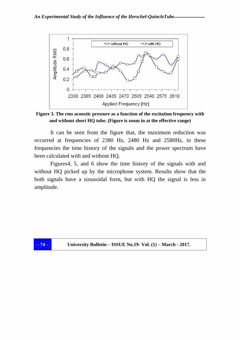
increment of 20 Hz. Figure 3, presents a full scanning of the acoustic field
in terms of rms pressure in volts as a function of excitation frequency with
and without short HQ tube, its dimensions;L =14cm, l =8cm, d=4cm, as
showed in the experimental setup section. From the results, the effect of the
short HQ on the noise level was in the range frequencies between 2300 to
2600 Hz.
An Experimental Study of the Influence of the Herschel-QuincleTube ــــــــــــ ــــ ــــــــــــــ
University Bulletin – ISSUE No.19- Vol. (1) – March - 2017. - 74 -
Figure 3. The rms acoustic pressure as a function of the excitation frequency with
and without short HQ tube. (Figure is zoom in at the effective range)
It can be seen from the figure that, the maximum reduction was
occurred at frequencies of 2380 Hz, 2480 Hz and 2580Hz, in these
frequencies the time history of the signals and the power spectrum have
been calculated with and without HQ.
Figures4, 5, and 6 show the time history of the signals with and
without HQ picked up by the microphone system. Results show that the
both signals have a sinusoidal form, but with HQ the signal is less in
amplitude.

,.Mohamed K. Al-Taleb & et.al ــــــــــــ ــــ ـــــــــــــــــــــــــــــــــــــــــــــــــــــــــــــــــــــــــــــــــــ ـــــــــ
University Bulletin – ISSUE No.19- Vol. (1) – March - 2017. - 75 -
Figure 4. Time history of the acoustic signals, without and with a short HQ at
frequency of 2380 Hz.
Figure 5. Time history of the acoustic signals, without and with a short HQ at
frequency of 2480 Hz.

An Experimental Study of the Influence of the Herschel-QuincleTube ــــــــــــ ــــ ــــــــــــــ
University Bulletin – ISSUE No.19- Vol. (1) – March - 2017. - 76 -
Figure 6. Time history of the acoustic signals, without and with a short HQ at
frequency of 2580 Hz.
Figures 7, 8, and 9 show the power spectrum at the applied
frequencies of 2380 Hz, 2480Hz, and 2580 Hz. Results show that, only one
peak at the same applied frequencies of signal generator, and also here less
amplitude of power spectrum with HQ tube, that means the signals are very
pure signal and with reduction in noise by using the HQ technique.
Figure 7. the power spectrum of the signal at the applied frequency of 2380 Hz
with and without HQ.

,.Mohamed K. Al-Taleb & et.al ــــــــــــ ــــ ـــــــــــــــــــــــــــــــــــــــــــــــــــــــــــــــــــــــــــــــــــ ـــــــــ
University Bulletin – ISSUE No.19- Vol. (1) – March - 2017. - 77 -
Figure 8. the power spectrum of the signal at the applied frequency of 2480 Hz
with and without HQ.
Figure 9. the power spectrum of the signal at the applied frequency of 2580 Hz
with and without HQ.

An Experimental Study of the Influence of the Herschel-QuincleTube ــــــــــــ ــــ ــــــــــــــ
University Bulletin – ISSUE No.19- Vol. (1) – March - 2017. - 78 -
Figure 10. shows full scanning of the RMS acoustic pressure as a
function of excitation frequency without and with long HQ tube, its
dimensions;L = 72 cm, l =36 and d = 4 cm, as mentioned in the
experimental setup section. Results showed that, the effective reduction of
noise was in the low frequencies range, with this specification of HQ tube,
the reduction wasin the range from 200 Hz to 300 Hz, compared with a
short HQ tube is very low. That mean the length of the HQ tube is very
important to control the reduction of noise. In second rig of HQ, the lowest
reduction of noise was occurred at frequency of 250 Hz, time history and
the power spectrum of the frequency are shown the Figure 11 and 12.
Figure 10. The rms acoustic pressure as a function of the excitation frequency, with
and without for a long HQ tube. (Figure is zoom in at the effective range)

,.Mohamed K. Al-Taleb & et.al ــــــــــــ ــــ ـــــــــــــــــــــــــــــــــــــــــــــــــــــــــــــــــــــــــــــــــــ ـــــــــ
University Bulletin – ISSUE No.19- Vol. (1) – March - 2017. - 79 -
Figure 11. Time history of the acoustic signals, without and with a long HQ at
frequency of 250 Hz.
Figure 12. Power spectrum of the signal at the applied frequency of 250 Hz without
and with a longHQ.

An Experimental Study of the Influence of the Herschel-QuincleTube ــــــــــــ ــــ ــــــــــــــ
University Bulletin – ISSUE No.19- Vol. (1) – March - 2017. - 80 -
Conclusions:
The present study describes an experimental work to investigate the
effects of the HQ tube length on the noise. The experimental results clearly
show that the cylindrical duct section of 20 cm diameter, when the short
HQ tube is placed 59 cm from the loudspeaker with a length of 14 cm has
the strong effect reduction of noise at high frequency range, in this type of
HQ tube the reduction of noise occurred in the range from 2300 to 2600
Hz, the maximum attenuation percentage of rmspressure was 60% at
frequency of 2480 Hz compared with a long tube placed at 31 cm from the
loudspeaker with length of 72 cm, The reduction was occurred at low range
of frequencies (200Hz to 300Hz), The maximum take place at frequency of
250 Hz, with a reduction percentage of 33%. In this paper; it has been
concluded that the length of the QH tube is play a significant role in noise
reduction and control, For low frequency the long tube should used to
attenuate the noise, and short HQ tube for high frequency.
References:
[1] Herschel, J. F. W,(1833) “On the absorption of light by coloured media,
viewed in connexion with the undulatory theory,” Philosophical
Magazine and Journal of Science, 3, pp 401-412.
[2] Quincke, G., (1866)“Ueberinterferenzapparate fur schallwellen,”
Annalen der Physik und Chemie, 128, pp177-192.
[3] Stewart, G. W., “The theory of the Herschel Quincke tube”, Physical
review, Vol,31, pp696-698, April, 1928

,.Mohamed K. Al-Taleb & et.al ــــــــــــ ــــ ـــــــــــــــــــــــــــــــــــــــــــــــــــــــــــــــــــــــــــــــــــ ـــــــــ
University Bulletin – ISSUE No.19- Vol. (1) – March - 2017. - 81 -
[4] Selamet, A., Dickey, N. S., and Novak, J. M., “The Herschel-Quincke
Tube: ATheoretical, Computational and Experimental Investigation”,
Journal of Acoustical Society of America, Vol. 96, No. 5, pages 3177-
3185, Nov., 1994.
[5] Selamet, A., Radavich, P. M., and Dickey, N. S., “Multi-Dimensional
Effects On Silencer Performance”, Noise-Con 94, pages 261-266, May,
1994.
[6] Selamet, A., Dickey, N. S., and Novak, J. M., “A Time-Domain
Computational
Simulation of Acoustic Silencers”, Journal of Vibrations and Acoustics,
Vol. 117, pages 323-331, July, 1995.
[7] Selamet, A., Radavich, P. M., “Effect of Expansion Chamber On the
Resonance Frequency of Side Branches and Herschel-Quincke Tubes”,
Proceedings of the American Society of Mechanical Engineers, NCA-
Vol. 22, pages 127-132, 1996.
[8] Selamet, A. and Easwaran, V., “Modified Herschel-Quincke tube:
Attenuation and resonance for n-duct configuration”, Journal of
Acoustical Society of America, Vol. 102, No. 1, pages 164-168, July,
1997.
[9] - Ayman El-Badawy1 and Wael El-Arna'outy,(2007). “Passive Niose
Control of a Burner-Combustor System of Turbo-Fan Engine” ICSV14,
9-12, Cairns, Australia.

An Experimental Study of the Influence of the Herschel-QuincleTube ــــــــــــ ــــ ــــــــــــــ
University Bulletin – ISSUE No.19- Vol. (1) – March - 2017. - 82 -
[10] - Raphaël F. Hallez, (2001) “Investigation of the Herschel-Quincke
Tube Conceptas a Noise ControlDevice for Turbofan Engines” Thesis,
Virginia Polytechnic Institute and State University.
[11] - Jerome P. Smith and Ricardo A. Burdisso, (2002) “Experiments
With Fixed and AdaptiveHerschel-Quincke Waveguides on the Prattand
Whitney JT15D Engine” NASA/CR-2002-211430.