An Experimental Investigation of Single and Multi-Tool Micro-EDM_2

Volume 1, Issue 1 (2013) 1-12 ISSN 2347 - 3258 International Journal of Advance Research and Innovation
1 IJARI
Experimental Studies for Accessing the Influence of
Micro-Dimple Area Density on Tribological Performance
of Mating Contacts
R. C. Singh a,*
, R. K. Pandey b, S. Maji
a
a Department of Mechanical Engineering, Delhi Technological University, New Delhi, India
b Department of Mechanical Engineering, I.I.T. Delhi, New Delhi, India
Abstract
The present research has been done to investigate the influence of the
relative motion of a plane surface with the other having micro-circular
dimples throughout the contact. Using pin-on-disk setup, experiments
have been carried out to study the influence of micro-dimple area
density on friction and specific wear rate at the interface of two
materials. Circular dimples are distributed in spiral array on the disk
face. Based on the experiments, better tribological results have been
achieved in the starved boundary lubrication mode.
1. Introduction
Existence of controlled dimple on mating
surfaces reduces the friction and improves the
tribological properties of the interface. Recently
researchers [1-4] have provided more thrusts on
improving the tribological issues using the surface
engineering as a tool. Surface texture for friction
reduction comprise of a flat surface interrupted by local micro-dimples. It has been established by
researchers that shallow micro-dimpled surface
generates innumerable tiny hydrodynamic bearings,
which separate the mating surfaces. Moreover, micro-
dimples act as oil reservoirs and wear
debris/contaminants trapping pits, which greatly
contribute in enhancing the tribological performances
of contacts even during the existence of
mixed/boundary lubrication. Effective lubrication at
the interface is influenced by many parameters such
as surface roughness, dimple depth, dimple area
density, dimple shape, and lubricant properties in addition to operating parameters. Therefore, the
objective of this paper is to explore the influence of
dimple area density on the friction and wear behaviors
of the contacts under various operating conditions.
Corresponding Author, E-mail address: [email protected]
All rights reserved: http://www.ijari.org
2. Experimentation
2.1 Specimen of disc, pin and lubricating oil
Specimen of mild steel plate of 165 mm diameter and
8 mm thick has been taken as shown in Fig.1a for
experimentation. Surface grinding and lapping fabrication processes has been performed on it to
reach up to the level of surface roughness of 0.2 to 0.3
micrometer root mean square value and checked by
surface roughness tester.
Cylindrical mild steel C-50 pin of diameter 12 mm
has been taken for test on mild steel circular plate as
dimensions shown in Fig.1b. The circular pin face has
labeled and checked by rubbing on soft paper to
remove debris and its flatness by ink impression on
paper respectively the length of pin is about 30 mm,
and diameter is 12 mm. The 26 mm length of pin is rigidly clamped and only 4 mm remains out in fixture
for test on disc so that bending may be minimized and
neglected during evaluation of tribological properties.
The lubricating oil (20W40) has been used which
have the following characteristics measured in
laboratory by true density meter, specific gravity
meter and kinematic viscosity meter are 0.89036
g/cm3, 0.8912 and 120.79248 mm2/sec at 40°C and
atmospheric pressure as per ASTM D-4052, D-287
and D-445 respectively.
Article Info
Article history:
Received 1 July 2013
Received in revised form
15 July 2013
Accepted 22 July 2013
Available online 1 August 2013
Keywords
Micro-Circular Dimples,
Pin-On-Disc,
Mating Contact,
Spiral Array

Volume 1, Issue 1 (2013) 1-12 ISSN 2347 - 3258 International Journal of Advance Research and Innovation
2 IJARI
Fig: 1a mild steel plate Fig. 1b Cylindrical mild steel C-50 pin
2.2 Specimen of wear test rig
The wear test rig as shown in Fig. 2a and the
specification in Table 1 has a motor that rotates with
different speed based on rheostat and the speed may
be fixed as desired between the ranges 200 to 2000
rpm of speeds. A horizontal plate fixture is attached
over which specimen of disc is bolted at four points.
Speed detector and wear measurement probe is
attached on it. Loading is done on pan that have
horizontal platform supporting the direction of gravity. The applied direction of force is transmitted
through wire and pulleys arrangements. Bell-crank
mechanism with uni-leverage is used and force
detector probe is used at the side to determine the
sheer friction force. Following are specification of
wear test rig.
Table: 1.
Details Description Remarks
Top
specimen
(mm)
Pin Dia
3,4,6,8,10 &
12
Material;
Ms
Bottom
specification
(mm)
Disc Diameter
165
Material:
Ms
Thickness 8
Speed (rpm) Disc Minimum
200
Maximum 2000
Frictional
force (N)
Between
pin &
disc
0 to 200
2.3 Dimples calculations
The minimum diameter of pin is 3 mm as per
specification of test rig so radial distance have been
grouped in set of 3 mm ranging from radius 10-70
mm on disc. Again the middle of those three have
been considered for calculating number of dimples
required to be fabricated on disc. At considered radius
having circumferential distance has been divided by
required 1 mm, 2 mm, 3 mm and 4 mm pitches to
know the number of dimples. So the four plates have been prepared of 420 microns for analysis of
minimum coefficient of friction.
The dimples are prepared in such a way that the
minimum diameter of pin was taken in consideration
of 3mm. The radial distance has been taken in interval
of one millimeter. The distribution of dimples along
circumferential distance is taken according to the
required pitch between two dimples.
For continuous three millimeter set of radial
distance, the angle between two dimples is divided
into three parts. The distribution of dimples starts
from reference line for the first circumferential distance.
For the second circumferential distance in the
same set of three radial distances, dimples starts from
second angle. The third circumferential distance
corresponding to third radial distance in the same set,
dimple starts from third angle. In this way all the
circumferential distance corresponding to set of three
radial distances, dimples are formed.

Volume 1, Issue 1 (2013) 1-12 ISSN 2347 - 3258 International Journal of Advance Research and Innovation
3 IJARI
Fig: 2. Schematic diagram of pin on disk test rig
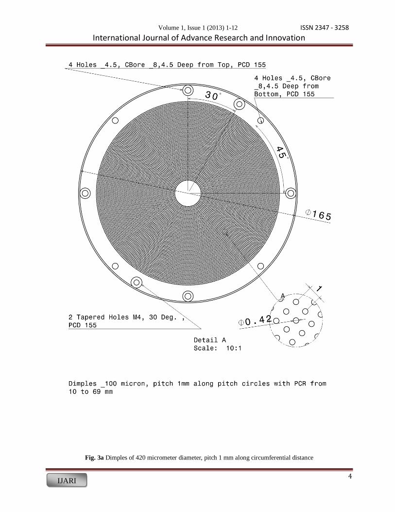
2.4 Specimen of disc with dimples
The dimples have been fabricated using chemical
etching process for different disc with the different
pitches. Drawings have been made by using Catia
software as shown in Fig. 3 as follows:
Volume 1, Issue 1 (2013) 1-12 ISSN 2347 - 3258 International Journal of Advance Research and Innovation
4 IJARI
Fig. 3a Dimples of 420 micrometer diameter, pitch 1 mm along circumferential distance

Volume 1, Issue 1 (2013) 1-12 ISSN 2347 - 3258 International Journal of Advance Research and Innovation
5 IJARI
Fig: 3b. Orthographic drawing of test plate with dimples of 420 mm diameter and having pitch 2 mm

Volume 1, Issue 1 (2013) 1-12 ISSN 2347 - 3258 International Journal of Advance Research and Innovation
6 IJARI
For determining of the friction and wear at the
interface formed between the pin end and disk face
and worn disc and pin figures have been shown in
Fig. 4. Both disk and pin are made of mild steel (C-
50). The end faces of mating bodies have been lapped
to the roughness of RMS to around 0.2 m. The face of disk is textured in the pattern as shown in Fig.1.
Circular micro-dimples of diameter of 420 m and
depth of 200-250 m are created by chemical etching process on mild steel disk. Tribological studies are
conducted for the loads characterized by pressure
varying in the range of 0.4- 1.4 MPa at sliding speeds
0.5-10 m/s (equivalent to 200 –2000 RPM).
Fig: 4a. Disc with elaborated part
Fig: 4b. Disc with worn track
3. Results and Discussions
Typical trends of friction coefficient µ at
different sliding speeds are plotted in Fig. 5 at load of
118 N for starved lubrication. Dimples on the contact
surface of disk having pitch 1mm improves the
tribological performance immensely in comparison to
disks having pitches 2, 3, and 4 mm.

Volume 1, Issue 1 (2013) 1-12 ISSN 2347 - 3258 International Journal of Advance Research and Innovation
7 IJARI
A plane and four dimpled disc having pitch 1
mm, 2 mm, 3 mm and 4 mm has been taken for
determining of coefficient of friction between pin and
disc. Experiments have been done by applying 118N (12 kg) load, 110 mm diameter of the disc, running at
500 rpm and pin has diameter 12 mm by applying
lubricant having properties shown in table. Also the
dry frictional coefficient between plain disc and pin is
0.233. The graph shown in figure, plane disc or zero
dimples has maximum value of order 0.079. Where as
dimpled have 0.0178, 0.072, 0.042 and 0.032
corresponding to disc having pitch 1 mm, 2 mm, 3
mm and 4 mm respectively. The plate having pitch 1
mm has minimum coefficient so considered for experiment.
The disc has been lubricated only once during
starting of experiment. The experiment has conducted
at different rpm by keeping the load of 12kgf constant
for 2400 second at diameter 110 mm. The frictional
force with respect to different rpm has been read to
plot variation of coefficient of friction vs load as
shown in fig. It has been observed that coefficient of
friction initially decreases and after that it increases
linearly with speed. There is no wear as shown by
wear characteristics in fig. leaving last part where
rapid grouth of wear take place.
0
0.02
0.04
0.06
0.08
0 1 2 3 4Coeff
icie
nt
of
fric
tion
, µ
Pitch (mm)
Variation of coefficient of friction with
speed (Mixed lubrication)
0
0.02
0.04
0.06
0.08
0.1
0.12
0.14
0.16
0.18
250 500 750 1000 1250 1500 1750 2000
Speed (rpm)
Co
effic
ien
t of f
rict
ion
0.08
0.10
0.12
0.14
0.16
0.18
500 750 1000 1250 1500 1750 2000
Coeff
icie
nt
of
fric
tion (
µ)
Speed (rpm)

Volume 1, Issue 1 (2013) 1-12 ISSN 2347 - 3258 International Journal of Advance Research and Innovation
8 IJARI
The variation coefficient of friction with respect to
load is shown in fig for mixed lubrication. It
decreases with load and at last it takes positive slop.
Whereas wearing of material shows that initially it
increase and after that it reduces.
Variation of wear with the speed
(Mixed lubrication at 118 N)
0
20
40
60
80
100
120
140
160
180
200
250 500 750 1000 1250 1500 1750 2000
Speed (rpm)
wea
r (m
g) x
E-4
0
4
8
12
16
20
500 750 1000 1250 1500 1750 2000
Wear
(mg)
Speed (rpm)
Variation of coefficient of friction with load
(Mixed lubrication at 1000 rpm)
0.07
0.08
0.09
0.1
0.11
40 60 80 100 120 140 160
Load (Newton)
Co
eff
icie
nt
of
fric
tio
n

Volume 1, Issue 1 (2013) 1-12 ISSN 2347 - 3258 International Journal of Advance Research and Innovation
9 IJARI
0.07
0.08
0.09
0.10
0.11
60 75 90 105 120 135 150
Coef
ficie
nt
of
fric
tion
(µ
)
Load (Newton)
Variation of wear with load
(Mixed lubrication at 1000 rpm)
0
2
4
6
8
10
12
14
40 60 80 100 120 140 160
Load (Newton)
We
ar
(mg
) x
E-4
0.2
0.4
0.6
0.8
1.0
1.2
1.4
60 75 90 105 120 135 150
Wear
(mg)
Load (Newton)

Volume 1, Issue 1 (2013) 1-12 ISSN 2347 - 3258 International Journal of Advance Research and Innovation
10 IJARI
The experiment has been carried out with
continuous flow of lubricating oil at the interface of
pin and disc to form hydrodynamic lubrication. The
load has been kept constant of 12kgf. And the speed
has been varied. It has been observed that coefficient
of friction continuously decreases with speed and
after certain period it remains constant at minimum
value nearly 0.03. The wear increases for very short
period and after that it decreases continuously to
become constant.
Variation of coefficient of friction with speed
(Hydrodynamic lubrication at 118 N)
0
0.01
0.02
0.03
0.04
0.05
0.06
0.07
0.08
250 500 750 1000 1250 1500 1750 2000
Speed (rpm)
Co
effic
ien
t of f
rict
ion
0.035
0.04
0.045
0.05
0.055
500 750 1000 1250 1500 1750 2000
Coeff
icie
nt
of
fric
tion (
µ)
Speed (rpm)
Variation of wear with speed
(Hydrodynamic lubrication at 118 N)
0
5
10
15
20
25
30
35
40
250 500 750 1000 1250 1500 1750 2000
Speed (rpm)
Wea
r (m
g) x
E-4

Volume 1, Issue 1 (2013) 1-12 ISSN 2347 - 3258 International Journal of Advance Research and Innovation
11 IJARI
The experiment has been carried out by keeping
the speed constant 1000 rpm at 110 mm diameter of
disc and varying load. It has been observed that during hydrodynamic lubrication coefficient of
friction initially at low load increases but after that
continuously decreases if last part would be taken as
straight. Wear characteristic follow the same variation of coefficient of friction with load as shown in fig.
0
1
2
3
4
500 750 1000 1250 1500 1750 2000
Wear (m
g)
Speed (rpm)
Variation of coefficient of friction with load
(Hydrodynamic lubrication at 1000 rpm)
0.04
0.045
0.05
0.055
0.06
0.065
0.07
40 60 80 100 120 140 160
Load (Newton)
Co
effic
ien
t of f
rict
ion
0.04
0.05
0.06
0.07
60 75 90 105 120 135 150
Coef
fici
ent
of
fric
tion (
µ)
Load (Newton)

Volume 1, Issue 1 (2013) 1-12 ISSN 2347 - 3258 International Journal of Advance Research and Innovation
12 IJARI
4. Summary
Based on the experiments reported in this paper,
authors have observed that micro-dimple area density
play great role in improving the coefficient of friction
at interface in boundary/mixed lubricating conditions.
The coefficient of friction first decreases then
increases continuously with speed whereas wear
remains constant. Whereas in hydrodynamic
lubrication coefficient of friction continuously
decreases with speed.
References
[1] D. F. Moore, “A History of Research on Surface
Texture Effects,” Wear, 13, 1969, 381-410
[2] U. Pettersson, S. Jacobson, “Influence of
Surface Texture on Boundary Lubricated Sliding
Contacts,” Tribol. Int., 36, 2003, 857-864
[3] I. Etsion, “State of the Art in Laser Surface
Texturing,” ASME J. Tribology, 127, 2005, 248-
253 [4] A. Erdemir, “Review of Engineered Tribological
Interfaces for Improved Boundary Lubrication,”
Tribol. Int., 38, 2005, 249-256
[5] M. Fowell, at. al, “Entrainment and Inlet
Suction: Two Mechanisms of Hydrodynamic
Lubrication in Textured Bearings,”ASME
Journal of Tibology,129(2), 2007,336-47.
[6] Y. Qiu, M. M. Khonsari, “Experimental
Investiggation of Tribological Performance of
Laser Textured Stainless Steel Rings,”
Tribology International, 2011
Variation of wear with load
(Hydrodynamic lubrication at 1000 N)
0
5
10
15
20
25
40 60 80 100 120 140 160
Load (Newton)
Wear
(mg
) x E
-4
0.0
0.5
1.0
1.5
2.0
2.5
60 75 90 105 120 135 150
Wear
(mg)
Load (Newton)