ALL PURPOSE POLY STORAGE SHEDS Poly Storage Shed
51
OWNER’S MANUAL / Instructions for Assembly • Tall Walk in Shed • Quick & Easy Assembly • Ridge Reinforced Walls • Wide Double Doors • Available in Various Sizes Call us for any missing or damaged parts. Do not return to the store. Poly Storage Shed Customer Service Hotline (800) 483-4674 www.uspolymersinc.com Requires two people and takes 2-3 hours for Installation. Ver: 1.0 A L L P U R P O S E P O L Y S T O R A G E S H E D S Size 10’ x 6’
Transcript of ALL PURPOSE POLY STORAGE SHEDS Poly Storage Shed
OWNER’S MANUAL / Instructions for Assembly
• Tall Walk in Shed• Quick & Easy Assembly • Ridge Reinforced Walls• Wide Double Doors• Available in Various Sizes
Call us for any missing or damaged parts.Do not return to the store.
Poly Storage Shed
CustomerService Hotline(800) 483-4674www.uspolymersinc.com
Requires two people and takes 2-3 hours for Installation.
Ver: 1.0
A L L P U R P O S E P O L Y S T O R A G E S H E D S
Size 10’ x 6’

Duramax Storage ShedLimited Ten Year Warranty
U.S. Polymer Inc. will send a replacement part free of charge, in the event of material defects and or workmanship for a period of ten years from the date of purchase.
This warranty is extended only to the original purchaser. A purchase receipt or other proof of date of original purchase will be required before warranty service is rendered. In no event shall we pay the cost of flooring, labor, installation or any other costs related thereto.
This warranty only covers failures due to defects in material or workmanship which occurs during normal use and does not extend to color change arising due to normal weathering or to damage resulting from misuse or neglect, commercial use, failure to follow assembly instructions and the owner’s manual (including proper anchoring of the shed), painting, forces of nature and other causes which is beyond our control.
Claims under this warranty must be made within the warranty period by calling 1-800-483-4674 or mail in a dated sales slip and clear photograph of the part to:
U.S. Polymers, Inc.6915 Slauson AvenueCommerce, CA 90040
We reserve the right to discontinue or change components. If a component has been discontinued or is not available,U.S. Polymers, Inc. reserves the right to substitute a component of equal quality as may be compatible.
Limits and Exclusions
There are no express warranties except as listed above. The warrantor shall not be liable for incidental or consequential damages resulting from the use of this product, or arising out of any breach of this warranty. All express warranties are limited to the warranty period set forth above . Some states do not allow the exclusion or limitation on how long an implied warranty lasts, so the above limitations may not apply to you.
This warranty gives you specific legal rights and you may also have other rights which vary from state to state or country to country.
IMPORTANT: USE HAND GLOVES TO PREVENT INJURY.
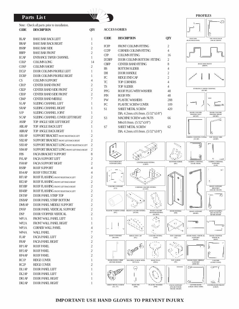
ACCESSORIES
CODE DESCRIPTION QTY
FCFP FRONT COLUMN FITTING 2CCFP CORNER COLUMN FITTNG 4CFP COLUMN FITTING 16DCBFP DOOR COLUMN BOTTOM FITTING 2CBFP CENTER BAND FITTING 8BS BOTTOM SLIDER 4DH DOOR HANDLE 2FC RIDGE END CAP 2TC TOP CORNERS 4TS TOP SLIDER 4PPG ROOF PLUG WITH WASHER 48PIN ROOF PIN 48PW PLASTIC WASHERS 288PC PLASTIC SCREW COVER 109S1 SHEET METAL SCREW 420
DIA. 4.2mm.x16.0mm. (5/32”x5/8”)S3 MACHINE SCREW with NUTS 66
M4x10.0mm. (5/32”x3/8”)S7 SHEET METAL SCREW 62
DIA. 4.2mm.x10.0mm. (5/32”x3/8”)
Note: Check all parts prior to installation.CODE DESCRIPTION QTY
BLAP BASE BAR BACK LEFT 1BRAP BASE BAR BACK RIGHT 1BSBP BASE BAR SIDE 2BBFP BASE BAR FRONT 2ECAP ENTRANCE TAPER CHANNEL 1COLP COLUMN LONG 14COSP COLUMN SHORT 2DCLP DOOR COLUMN PROFILE LEFT 1DCRP DOOR COLUMN PROFILE RIGHT 1CS COLUMN SUPPORT 4CB1P CENTER BAND FRONT 2CB2P CENTER BAND SIDE FRONT 2CB3P CENTER BAND SIDE FRONT 2CB4P CENTER BAND MIDDLE 7SLAP SLIDING CHANNEL LEFT 1SRAP SLIDING CHANNEL RIGHT 1SJP SLIDING CHANNEL JOINT 1SCAP SLIDING CHANNEL COVER LEFT/RIGHT 2ASBP TOP ANGLE SIDE LEFT/RIGHT 2ABLAP TOP ANGLE BACK LEFT 1ABRAP TOP ANGLE BACK RIGHT 1SB1AP SUPPORT BRACKET FRONT RIGHT/BACK LEFT 2SB2AP SUPPORT BRACKET FRONT LEFT/BACK RIGHT 2SB3AP SUPPORT BRACKET LONG FRONT RIGHT/BACK LEFT 2SB4AP SUPPORT BRACKET LONG FRONT LEFT/BACK RIGHT 2FBS FACIA BRACKET SUPPORT 8FSLAP FACIA SUPPORT LEFT 2FSRAP FACIA SUPPORT RIGHT 2RSBP ROOF SUPPORT 4RS4AP ROOF STRUCTURE 4RF1AP ROOF FLASHING FRONT RIGHT/BACK LEFT 2RF2AP ROOF FLASHING FRONT LEFT/BACK RIGHT 2RF3BP ROOF FLASHING FRONT LEFT/BACK RIGHT 2RF4BP ROOF FLASHING FRONT RIGHT/BACK LEFT 2DSTAP DOOR PANEL STRIP TOP 2DSBAP DOOR PANEL STRIP BOTTOM 2DMSAP DOOR PANEL MIDDLE SUPPORT 2DVSP DOOR PANEL VERTICAL SUPPORT 2DSP DOOR STOPPER VERTICAL 2WP1A FRONT WALL PANEL LEFT 1WP2A FRONT WALL PANEL RIGHT 1WP3A CORNER WALL PANEL 4WP4A WALL PANEL 7FLAP FACIA PANEL LEFT 2FRAP FACIA PANEL RIGHT 2RP1AP ROOF PANEL 2RP2AP ROOF PANEL 2RP4AP ROOF PANEL 2RC1P RIDGE COVER 1RC2P RIDGE COVER 2DL1AP DOOR PANEL LEFT 1DL2AP DOOR PANEL LEFT 1DR1AP DOOR PANEL RIGHT 1DR2AP DOOR PANEL RIGHT 1
Parts List
BASE BAR(BLAP, BRAP, BSBP)
PROFILES
IMPORTANT: USE HAND GLOVES TO PREVENT INJURY.
TOP ANGLE BACK (ABLAP, ABRAP)
BASE BAR FRONT(BBFP)
DOOR COLUMNPROFILE LEFT
(DCLP)
ENTRANCE TAPER CHANNEL(ECAP)
DOOR COLUMNPROFILE RIGHT
(DCRP)
SLIDING CHANNEL COVER(SCAP)
TOP ANGLE SIDE(ASBP)
SLIDING CHANNEL(SLAP, SRAP)
SLIDING CHANNEL SUPPORT
(SJP)
ROOF SUPPORT BRACKET
(SB1AP, SB2AP)
ROOF FLASHING(RF1AP, RF2AP,RF3BP, RF4BP
ROOF SUPPORT(RSBP)
DOOR PANEL VERTICAL SUPPORT
(DVSP)
DOOR STOPPER VERTICAL
(DSP)
DOOR PANEL MIDDLE SUPPORT(DMSAP)
COLUMN(COLP, COSP)
CENTER BAND(CB2P, CB3P, CB4P)
CENTER BAND FRONT(CB1P)
PLASTIC WASHER(PW)
TOP SLIDER(TS)
TOP CORNERS(TC)
DOOR HANDLE(DH)
BOTTOM SLIDER(BS)
CENTER BAND FITTING(CBFP)
CORNER COLUMN FITTING(CCFP)
COLUMN FITTING(CFP)
ROOF PLUG(PPG)
ROOF PIN(PIN)
RIDGE END CAP(FC)
MACHINE SCREW WITH NUT (S3)
SHEET METAL SCREW(S1, S7)
FACIA SUPPORT(FSLAP, FSRAP,SB3AP, SB4AP)
DOOR PANEL STRIP(DSTAP, DSBAP)
ROOF SUPPORT(RS4AP)
PLASTIC SCREW COVER(PC)
COLUMN SUPPORT(CS)
FACIA BRACKET SUPPORT (FBS)
FRONT COLUMN FITTING(FCFP)
DOOR COLUMN BOTTOM FITTING
(DCBFP)
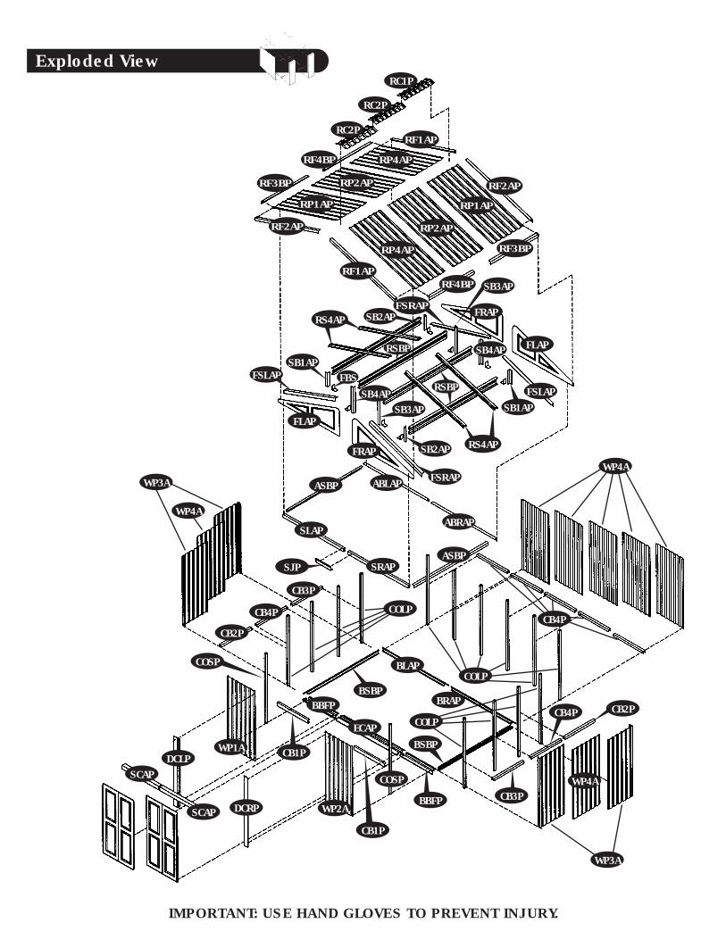
Exploded View
IMPORTANT: USE HAND GLOVES TO PREVENT INJURY.
RC2P
RC2P
RC1P
RF3BP
RF4BP
RF2AP
RF1AP
RF2AP
RF1AP
RF3BP
RF4BP
RS4AP
FLAP
FRAP
RSBP
FSRAPFRAP
FLAP
FSLAPSB1AP
SB4AP
SB2AP
SB1APFBS
SB4APRSBP
RS4APSB2AP
ASBP ABLAP
ASBP
SLAP
SRAPSJP
CB3P
CB4P
CB2P
COLP
WP3A
WP4A
CB4P
WP3A
WP4A
BRAP
BLAP
BSBPBBFP
ECAP
COSP
WP2A
DCLPSCAP
SCAP DCRP
CB1P
WP1A
SB3AP
FSLAP
FSRAP
ABRAP
COLP
COLP
CB1PBSBP
WP4A
COSP
BBFP
RP4AP
RP2AP
RP1AP
RP2AP
RP1AP
RP4AP
CB3P
CB2PCB4P
SB3AP
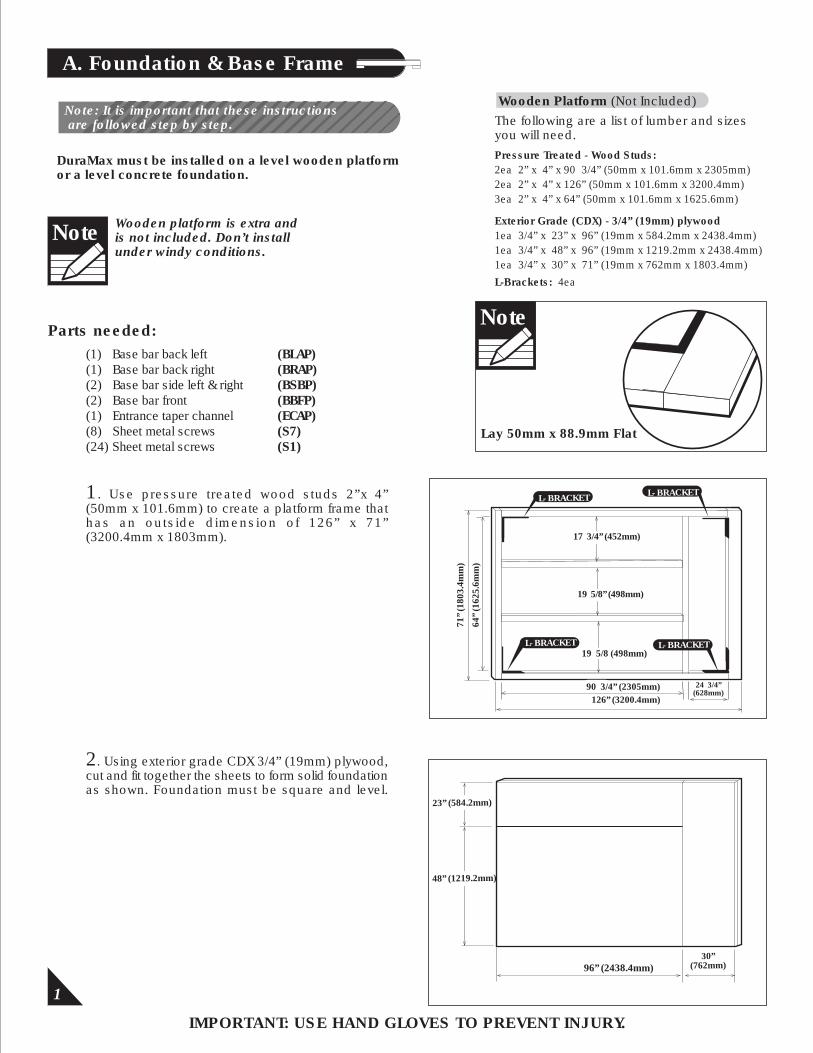
A. Foundation & Base Frame
1. Use pressure treated wood studs 2”x 4”(50mm x 101.6mm) to create a platform frame that has an outside dimension of 126” x 71”(3200.4mm x 1803mm).
DuraMax must be installed on a level wooden platformor a level concrete foundation.
2. Using exterior grade CDX 3/4” (19mm) plywood, cut and fit together the sheets to form solid foundation as shown. Foundation must be square and level.
Note: It is important that these instructions are followed step by step.
Wooden platform is extra andis not included. Don’t installunder windy conditions.
1
Note
Lay 50mm x 88.9mm Flat
Note
96” (2438.4mm)30”
(762mm)
(1) Base bar back left (BLAP)(1) Base bar back right (BRAP)(2) Base bar side left & right (BSBP) (2) Base bar front (BBFP)(1) Entrance taper channel (ECAP)(8) Sheet metal screws (S7)(24) Sheet metal screws (S1)
Parts needed:
IMPORTANT: USE HAND GLOVES TO PREVENT INJURY.
The following are a list of lumber and sizesyou will need.
Wooden Platform (Not Included)
Pressure Treated - Wood Studs:2ea 2” x 4” x 90 3/4” (50mm x 101.6mm x 2305mm)2ea 2” x 4” x 126” (50mm x 101.6mm x 3200.4mm)3ea 2” x 4” x 64” (50mm x 101.6mm x 1625.6mm)
Exterior Grade (CDX) - 3/4” (19mm) plywood1ea 3/4” x 23” x 96” (19mm x 584.2mm x 2438.4mm)1ea 3/4” x 48” x 96” (19mm x 1219.2mm x 2438.4mm)1ea 3/4” x 30” x 71” (19mm x 762mm x 1803.4mm)
L-Brackets: 4ea
L- BRACKETL- BRACKET
L- BRACKET L- BRACKET
23” (584.2mm)
48” (1219.2mm)
71”
(180
3.4m
m)
17 3/4” (452mm)
19 5/8” (498mm)
19 5/8 (498mm)
90 3/4” (2305mm)126” (3200.4mm)
24 3/4”(628mm)
64”
(162
5.6m
m)
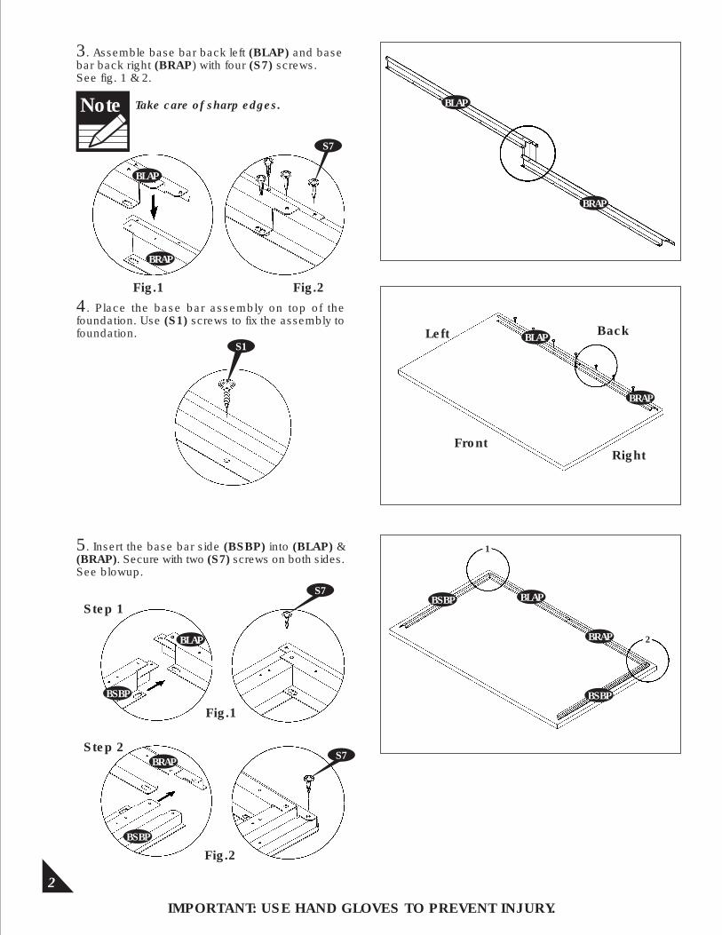
3. Assemble base bar back left (BLAP) and base bar back right (BRAP) with four (S7) screws.See fig. 1 & 2.
4. Place the base bar assembly on top of the foundation. Use (S1) screws to fix the assembly to foundation.
2
5. Insert the base bar side (BSBP) into (BLAP) & (BRAP). Secure with two (S7) screws on both sides.See blowup.
Fig.1 Fig.2
BLAP
S7
BLAP
BRAP
BLAP
BRAP
FrontRight
Left Back
Fig.1
Fig.2
Step 1
Step 2
BLAP
BRAP
BSBP
BSBP
BSBP
BLAP
BRAP
BSBP
S7
Take care of sharp edges.Note
IMPORTANT: USE HAND GLOVES TO PREVENT INJURY.
S1
BRAP
S7
1
2
3
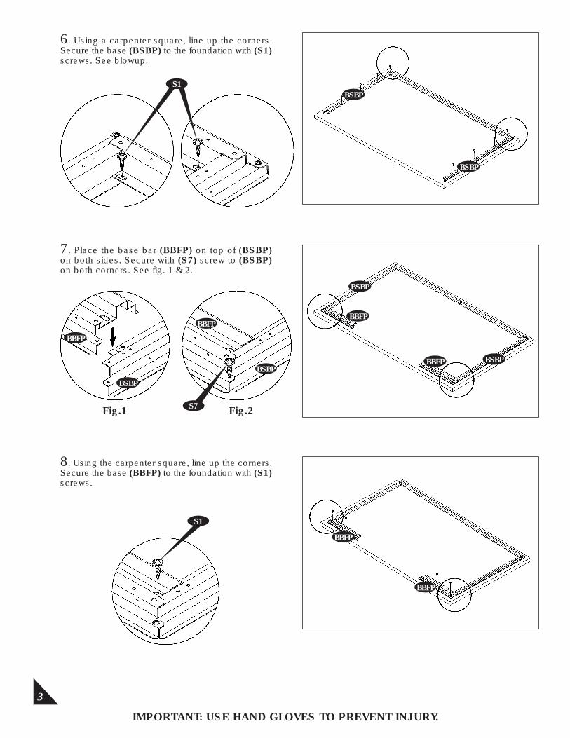
6. Using a carpenter square, line up the corners.Secure the base (BSBP) to the foundation with (S1) screws. See blowup.
7. Place the base bar (BBFP) on top of (BSBP) on both sides. Secure with (S7) screw to (BSBP) on both corners. See fig. 1 & 2.
8. Using the carpenter square, line up the corners.Secure the base (BBFP) to the foundation with (S1) screws.
BSBP
BBFP
BBFP
BBFP
BSBP
BBFP
BSBP
Fig.1 Fig.2
BBFP
BBFP
S1
BSBP
IMPORTANT: USE HAND GLOVES TO PREVENT INJURY.
S1
S7
BSBP
BSBP

4
9. Place the entrance taper channel (ECAP) on top of the (BBFP). Secure with (S1) screws to the foundation. See fig. 1 & 2.
10. Measure in all direction as shown in figure. Make the base bar assembly in a perfect square.
BBFP
BBFP
S1
Fig.1 Fig.2
ECAP
ECAP
BBFP
BBFP
Parts Needed:(2) Column short (COSP)(14) Column long (COLP)(4) Column support (CS)(1) Wall panel front left (WP1A)(1) Wall panel front right (WP2A)(4) Wall panel corner (WP3A)(7) Wall panel side (WP4A)(1) Sliding channel right (SRAP)(1) Sliding channel left (SLAP)(1) Sliding channel joint (SJP)(2) Sliding channel cover left / right (SCAP)(2) Top angle side left & right (ASBP)(1) Top angle back left (ABLAP)(1) Top angle back right (ABRAP)(2) Center band front (CB1P)
B. Walls & Columns
All panels are clearly markedand care should be taken touse the correct one.
Note
10a. (Concrete foundation) Using a carpenter’s square, line up corners. Align Base bars, mark the concrete at the holes in the base and drill concrete with 1/4” (dia. 6mm) concrete bit to accept anchor bolts to a 1 3/4” (44mm) depth. Replace base and secure with 1/4” x 1 3/8” (M6 x 35mm) anchor bolts (not provided).
Concrete foundation
BBFP
ECAP
BSBP
BSBP
BRAP
BLAP
(3037mm)
(1569mm)
(2) Center band side front (CB2P)(2) Center band side back (CB3P)(7) Center band middle (CB4P)(1) Door column profile left(DCLP)(1) Door column profile right(DCRP)(4) Corner column fitting (CCFP)(8) Center band fitting (CBFP)(2) Front column fitting (FCFP)(16) Column fitting (CFP)(4) Top slider (TS)(156) Plastic washer (PW)(260) Sheet metal screw (S1)(16) Sheet metal screw (S7)
IMPORTANT: USE HAND GLOVES TO PREVENT INJURY.
(1569mm)
(3037mm)
5
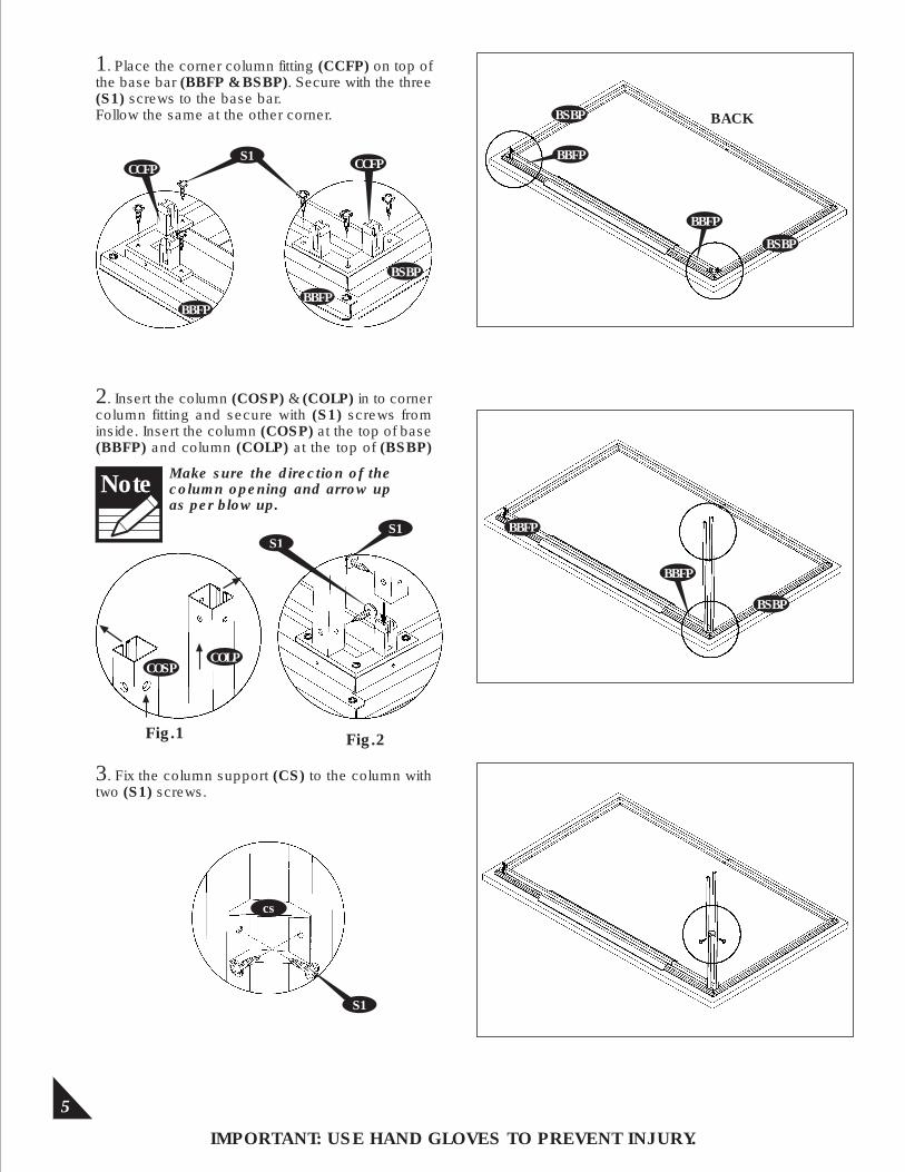
1. Place the corner column fitting (CCFP) on top of the base bar (BBFP & BSBP). Secure with the three (S1) screws to the base bar.Follow the same at the other corner.
2. Insert the column (COSP) & (COLP) in to corner column fitting and secure with (S1) screws from inside. Insert the column (COSP) at the top of base (BBFP) and column (COLP) at the top of (BSBP)
3. Fix the column support (CS) to the column with two (S1) screws.
Make sure the direction of the column opening and arrow up as per blow up.
Note
Fig.1 Fig.2
CCFP
BBFP
COSP
S1
COLP
S1
BSBP
IMPORTANT: USE HAND GLOVES TO PREVENT INJURY.
BACK
BBFP
BSBP
CCFPS1
S1BBFP
cs
BSBP
BSBP
BBFP
BBFP
BBFP
6
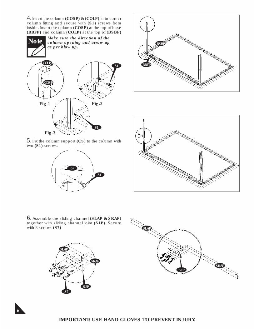
4. Insert the column (COSP) & (COLP) in to corner column fitting and secure with (S1) screws from inside. Insert the column (COSP) at the top of base (BBFP) and column (COLP) at the top of (BSBP)
5. Fix the column support (CS) to the column with two (S1) screws.
6. Assemble the sliding channel (SLAP & SRAP) together with sliding channel joint (SJP). Secure with 8 screws (S7)
Fig.1 Fig.2
BSBP
IMPORTANT: USE HAND GLOVES TO PREVENT INJURY.
S1
S1
COLP
COSP
Fig.3
BBFP
cs
S1
SLAP
SJPSRAP
SJPS7
SRAP
SLAP
Make sure the direction of the column opening and arrow up as per blow up.
Note
7
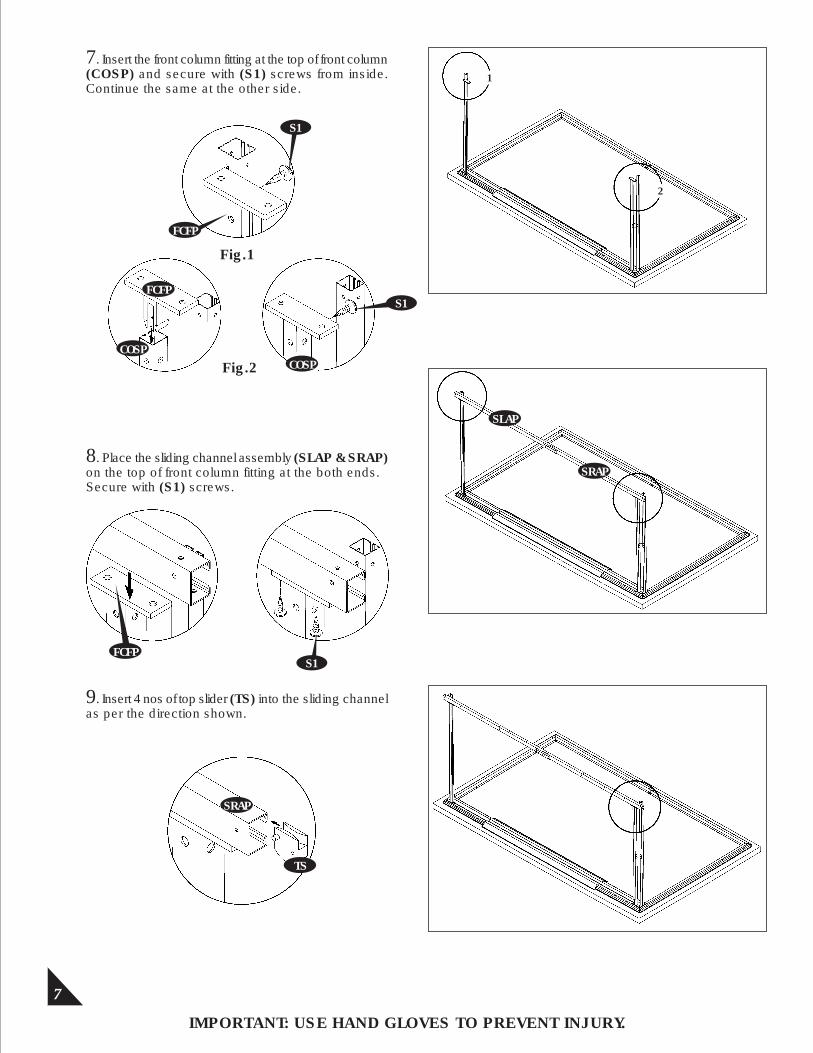
7. Insert the front column fitting at the top of front column (COSP) and secure with (S1) screws from inside. Continue the same at the other side.
8. Place the sliding channel assembly (SLAP & SRAP) on the top of front column fitting at the both ends.Secure with (S1) screws.
9. Insert 4 nos of top slider (TS) into the sliding channel as per the direction shown.
Fig.1
Fig.2COSP
IMPORTANT: USE HAND GLOVES TO PREVENT INJURY.
S1
FCFP
SLAP
SRAP
FCFPS1
SRAP
TS
FCFP
S1
COSP
2
1
8
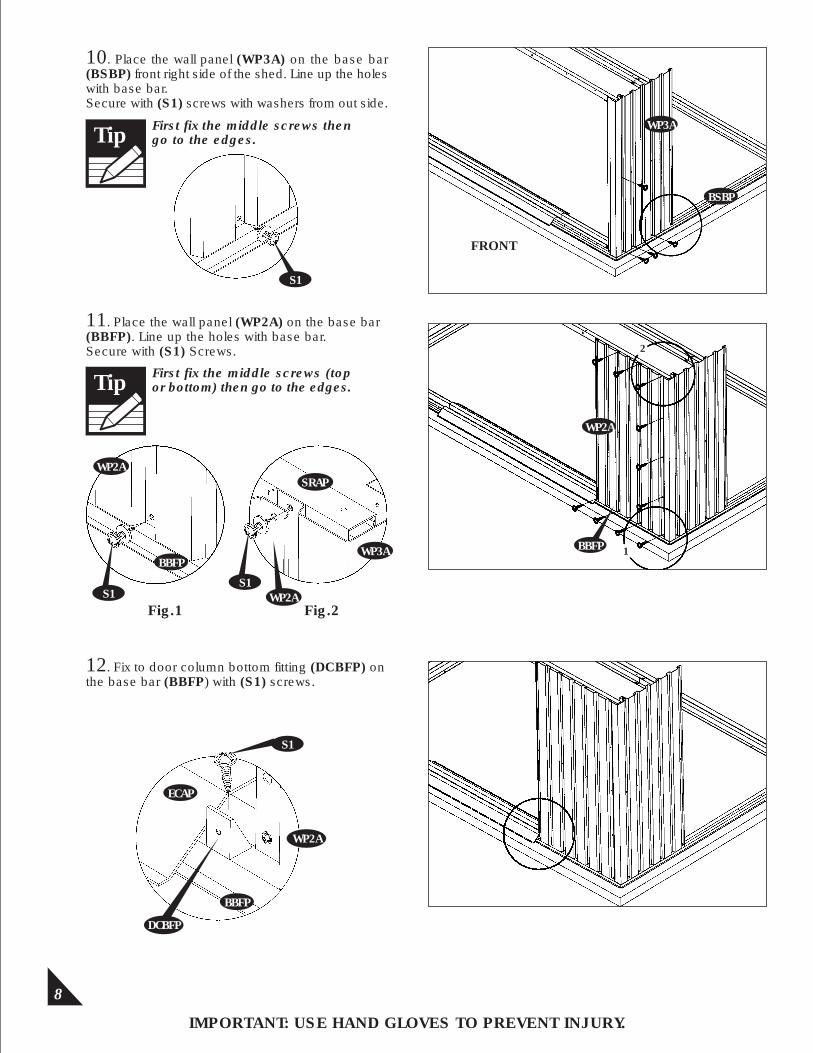
10. Place the wall panel (WP3A) on the base bar (BSBP) front right side of the shed. Line up the holes with base bar.Secure with (S1) screws with washers from out side.
11. Place the wall panel (WP2A) on the base bar (BBFP). Line up the holes with base bar.Secure with (S1) Screws.
Fig.1 Fig.2
IMPORTANT: USE HAND GLOVES TO PREVENT INJURY.
WP3A
BSBP
S1
WP2A
WP2A
BBFP
S1S1
SRAP
WP3A
2
1
WP2A
FRONT
BBFP
First fix the middle screws then go to the edges.Tip
First fix the middle screws (top or bottom) then go to the edges.Tip
S1
ECAP
BBFP
DCBFP
WP2A
12. Fix to door column bottom fitting (DCBFP) onthe base bar (BBFP) with (S1) screws.
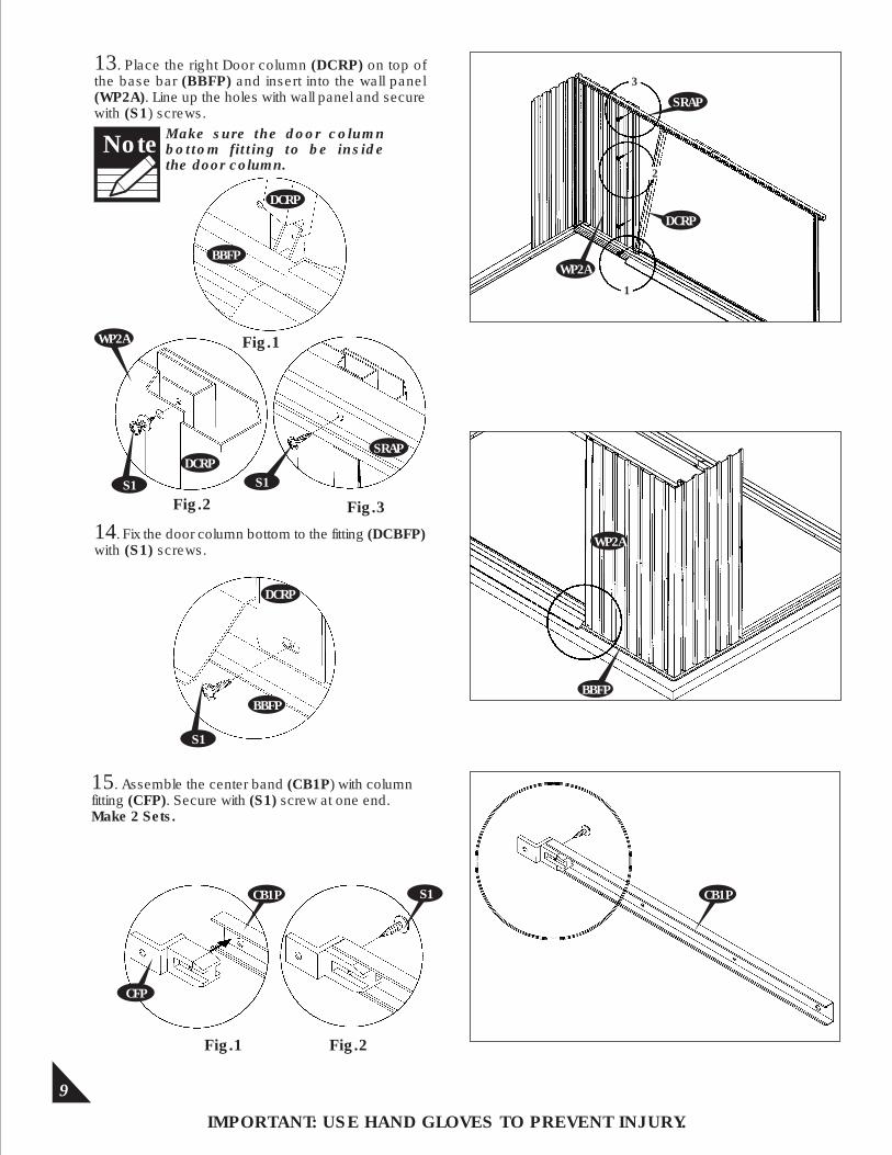
13. Place the right Door column (DCRP) on top of the base bar (BBFP) and insert into the wall panel (WP2A). Line up the holes with wall panel and secure with (S1) screws.
S1
BBFP
DCRP
Fig.2
DCRP
Fig.3
3
1
2
WP2A
S1
SRAP
SRAP
DCRP
WP2A
Fig.1
9
IMPORTANT: USE HAND GLOVES TO PREVENT INJURY.
14. Fix the door column bottom to the fitting (DCBFP)with (S1) screws. WP2A
BBFP
15. Assemble the center band (CB1P) with column fitting (CFP). Secure with (S1) screw at one end.Make 2 Sets.
Fig.1 Fig.2
CB1P
CFP
S1 CB1P
DCRP
BBFP
S1
Note Make sure the door columnbottom fitting to be insidethe door column.
10
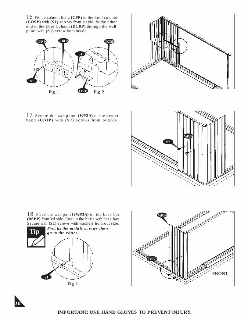
16. Fix the column fitting (CFP) to the front column (COSP) with (S1) screws from inside, fix the other end to the Door Column (DCRP) through the wall panel with (S1) screw from inside.
17. Secure the wall panel (WP2A) to the center band (CB1P) with (S7) screws from outside.
Fig.1 Fig.2
IMPORTANT: USE HAND GLOVES TO PREVENT INJURY.
DCRP
S1
CB1P
CB1P
S1
COSP2
1
S7
WP2A
18. Place the wall panel (WP3A) on the base bar (BSBP) front left side. Line up the holes with base bar. Secure with (S1) screws with washers from out side.
Fig.1
WP3A
BSBP
S1FRONT
First fix the middle screws then go to the edges.Tip

11
Make sure the overlappingposition of panels is asshown in fig. 2.
Note
19. Place the wall panel (WP1A) on the base bar (BBFP). Line up the holes with base bar.Secure with (S1) screws.
21. Place the left Door Column (DCLP) on top of the base bar (BBFP) and insert in to the wall panel (WP1A). Line up the holes with wall panel and secure with (S1) screws.
IMPORTANT: USE HAND GLOVES TO PREVENT INJURY.
S1
WP1A
BBFP WP3A WP1AFig.1 Fig.2
S1
Fig.1
Fig.3
WP1A
Fig.2
S1
S1
DCLP
3
2
1
DCLP WP1A
SLAP
BBFP
WP1A
SLAP
DCLP
BBFP
First fix the middle screws (top or bottom) then go to the edges.Tip
20. Fix to door column bottom fitting (DCBFP) onthe base bar (BBFP) with (S1) screws.
S1
BBFP
ECAP
DCBFP
WP1A
Note Make sure the door columnbottom fitting to be insidethe door column.

12
IMPORTANT: USE HAND GLOVES TO PREVENT INJURY.
Fig.1 Fig.2
23. Fix the Column fitting (CFP) to the front Column (COSP) with (S1) screw from inside.Fix other end to the Door Column (DCLP) through the wall panel with (S1) screw from inside.
S1
DCLP
CB1P
S1
CFP 21
WP1A
24. Secure the wall panel (WP1A)to the centre band (CB1P) with (S7) screws from outside.
22. Fix the door column bottom to the fitting (DCBFP) with (S1) Screws.
S1
DCLP
13
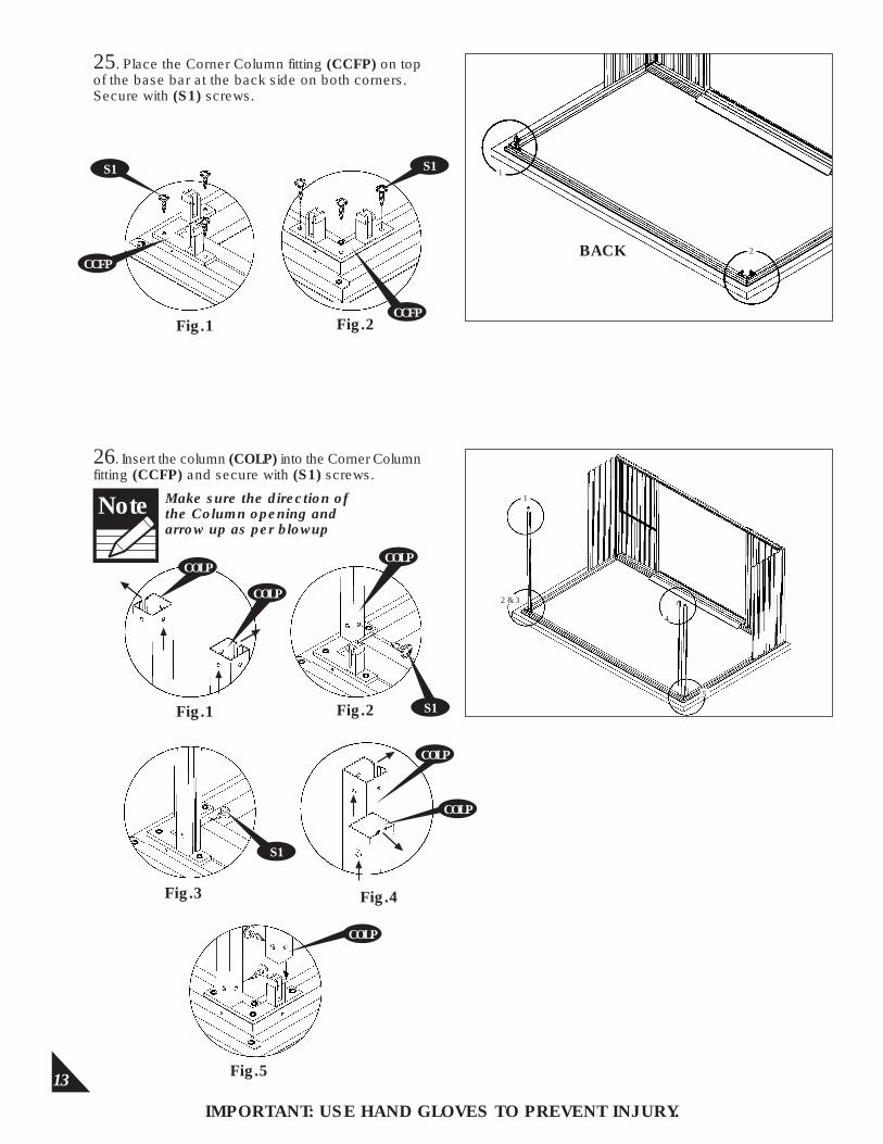
25. Place the Corner Column fitting (CCFP) on top of the base bar at the back side on both corners. Secure with (S1) screws.
26. Insert the column (COLP) into the Corner Column fitting (CCFP) and secure with (S1) screws.
Fig.1 Fig.2
IMPORTANT: USE HAND GLOVES TO PREVENT INJURY.
S1
Make sure the direction of the Column opening and arrow up as per blowup
Note
CCFP
S1
COLP
COLP
S1
CCFP
S1 1
2
Fig.1 Fig.2
Fig.3 Fig.4
COLP
COLP
Fig.5
1
2 & 3
4
5
BACK
COLP
COLP
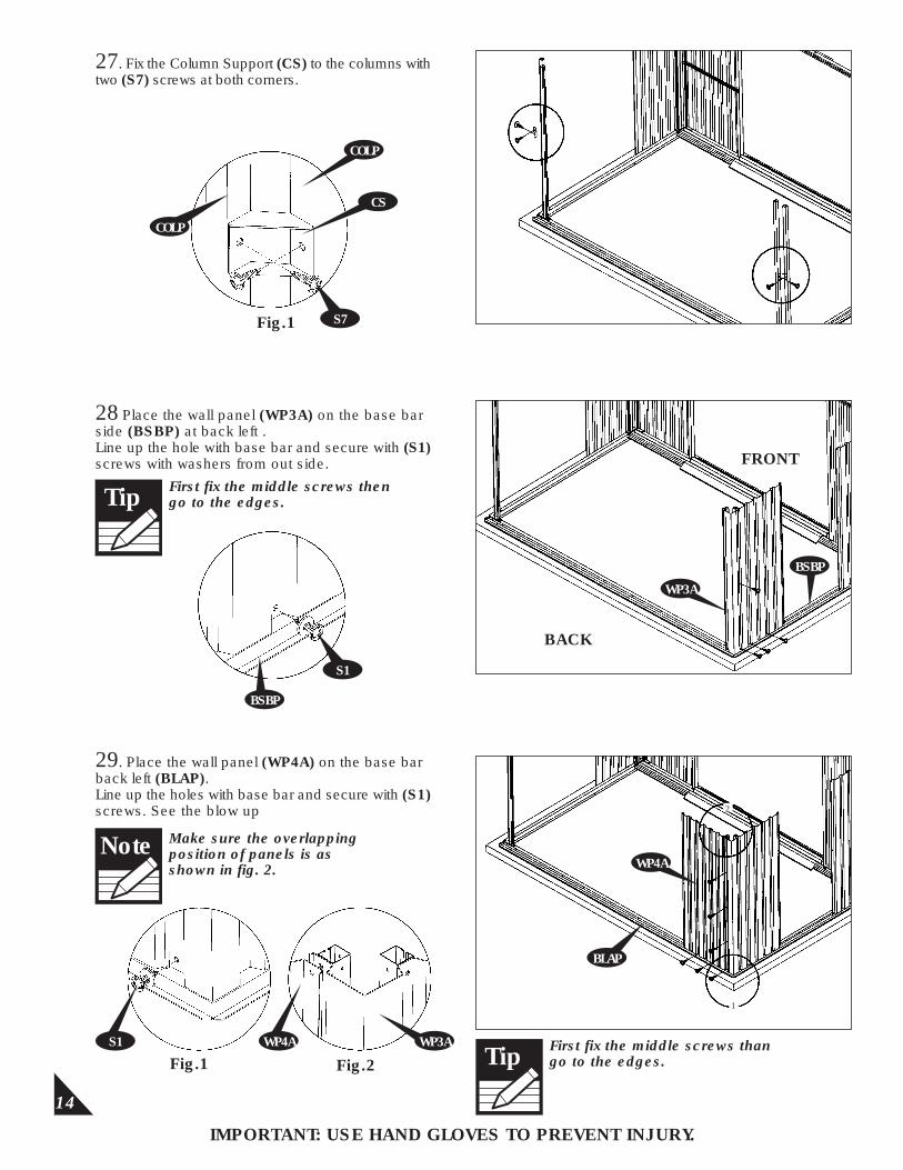
Fig.1
14
27. Fix the Column Support (CS) to the columns with two (S7) screws at both corners.
28 Place the wall panel (WP3A) on the base bar side (BSBP) at back left .Line up the hole with base bar and secure with (S1) screws with washers from out side.
29. Place the wall panel (WP4A) on the base bar back left (BLAP).Line up the holes with base bar and secure with (S1) screws. See the blow up
Fig.1 Fig.2
IMPORTANT: USE HAND GLOVES TO PREVENT INJURY.
S7
COLP
COLP
CS
S1
BSBP
S1 WP4A WP3A
FRONT
BACK
WP3A
WP4A
1
2
BSBP
BLAP
Make sure the overlappingposition of panels is asshown in fig. 2.
Note
First fix the middle screws then go to the edges.Tip
First fix the middle screws than go to the edges.Tip
15
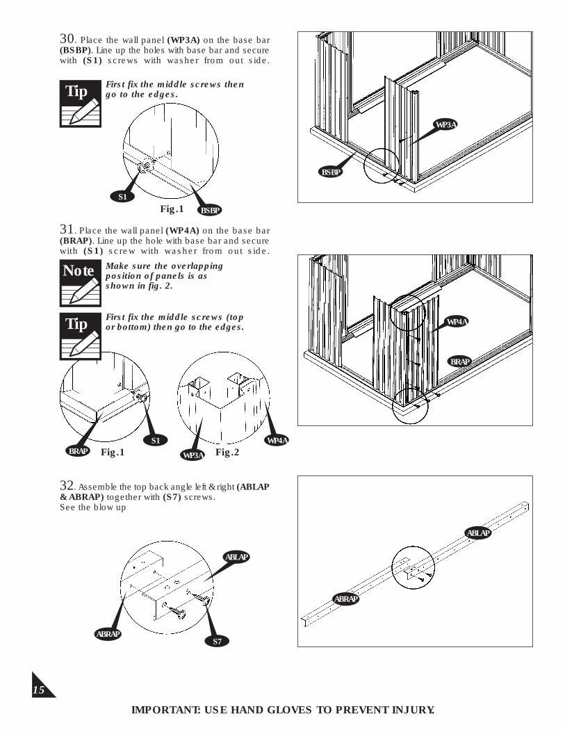
30. Place the wall panel (WP3A) on the base bar (BSBP). Line up the holes with base bar and secure with (S1) screws with washer from out side.
31. Place the wall panel (WP4A) on the base bar (BRAP). Line up the hole with base bar and secure with (S1) screw with washer from out side.
32. Assemble the top back angle left & right (ABLAP & ABRAP) together with (S7) screws.See the blow up
Fig.1
Fig.1 Fig.2
DCL
BBF
IMPORTANT: USE HAND GLOVES TO PREVENT INJURY.
WP3A
S1
S1BRAP
WP4A
BRAP
WP4A
ABRAP
ABLAP
S7
ABLAP
ABRAP
BSBP
WP3A
BSBP
Make sure the overlappingposition of panels is asshown in fig. 2.
Note
First fix the middle screws then go to the edges.Tip
First fix the middle screws (top or bottom) then go to the edges.Tip
16
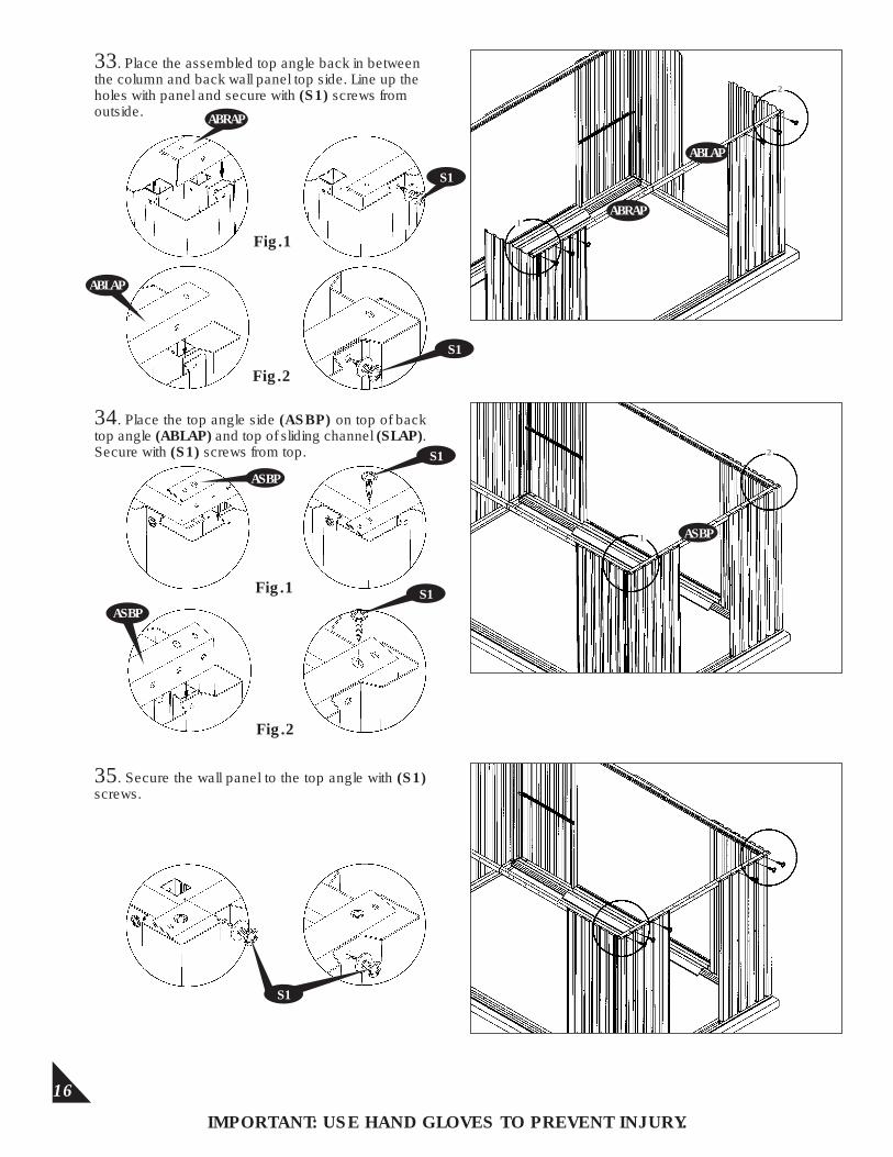
33. Place the assembled top angle back in between the column and back wall panel top side. Line up the holes with panel and secure with (S1) screws fromoutside.
IMPORTANT: USE HAND GLOVES TO PREVENT INJURY.
ABRAP
S1
ABLAP
S1
34. Place the top angle side (ASBP) on top of back top angle (ABLAP) and top of sliding channel (SLAP). Secure with (S1) screws from top.
Fig.1
Fig.2
1
2
ASBP
ASBP
S1
S1Fig.1
Fig.2
35. Secure the wall panel to the top angle with (S1) screws.
S1
2
1
ABLAP
ABRAP
ASBP
S1
17
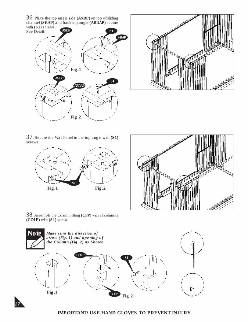
37. Secure the Wall Panel to the top angle with (S1) screws.
IMPORTANT: USE HAND GLOVES TO PREVENT INJURY.
36. Place the top angle side (ASBP) on top of sliding channel (SRAP) and back top angle (ABRAP) secure with (S1) screws.See Details.
Fig.1
Fig.2
38. Assemble the Column fitting (CFP) with all columns (COLP) with (S1) screw.
Fig.1Fig.2
ASBP
2
Fig.1 Fig.2
Make sure the direction of arrow (Fig. 1) and opening of the Column (Fig. 2) as Shown
Note
COLP
CFP
S1
SRAP
ASBP
ABRAP
1
1
2
1
2
S1
S1
18
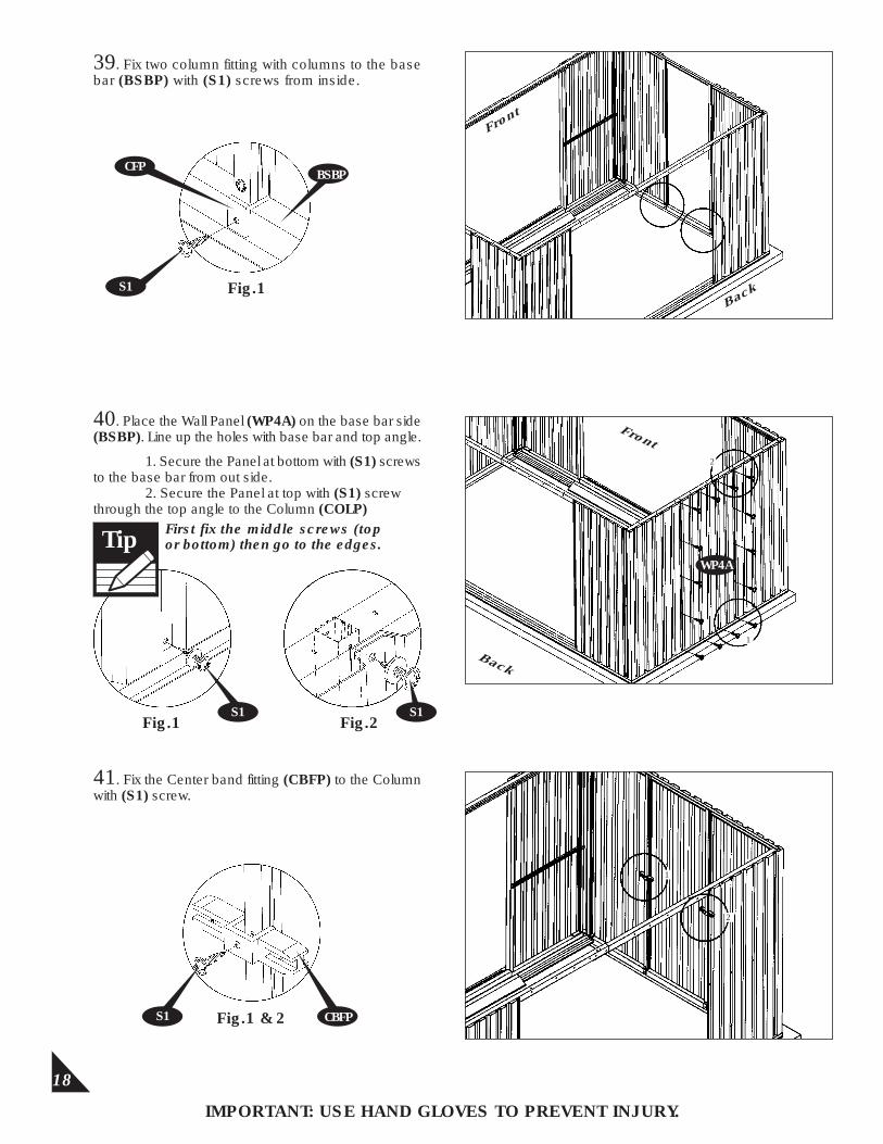
39. Fix two column fitting with columns to the base bar (BSBP) with (S1) screws from inside.
Fig.1
IMPORTANT: USE HAND GLOVES TO PREVENT INJURY.
40. Place the Wall Panel (WP4A) on the base bar side (BSBP). Line up the holes with base bar and top angle.
Front
BackS1
CFPBSBP
Fig.1 Fig.2
Front
Back
1. Secure the Panel at bottom with (S1) screws to the base bar from out side.
2. Secure the Panel at top with (S1) screw through the top angle to the Column (COLP)
41. Fix the Center band fitting (CBFP) to the Column with (S1) screw.
Fig.1 & 2S1 CBFP
2
1
1
2
WP4A
S1 S1
First fix the middle screws (top or bottom) then go to the edges.Tip
19
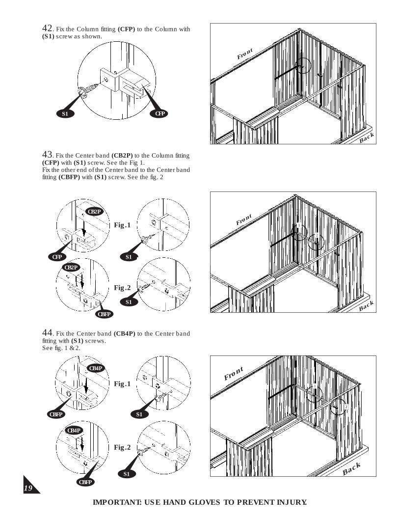
42. Fix the Column fitting (CFP) to the Column with (S1) screw as shown.
IMPORTANT: USE HAND GLOVES TO PREVENT INJURY.
44. Fix the Center band (CB4P) to the Center band fitting with (S1) screws.See fig. 1 & 2.
Front
Back
S1 CFP
43. Fix the Center band (CB2P) to the Column fitting (CFP) with (S1) screw. See the Fig 1.Fix the other end of the Center band to the Center band fitting (CBFP) with (S1) screw. See the fig. 2
CFP
CB2P
S1
Fig.1
Fig.2
CB2P
CBFP
S1
Front
Back
Front
Back
1
2
CBFP
CB4P
S1
Fig.1
Fig.2
CBFP
CB4P
S1
1
2
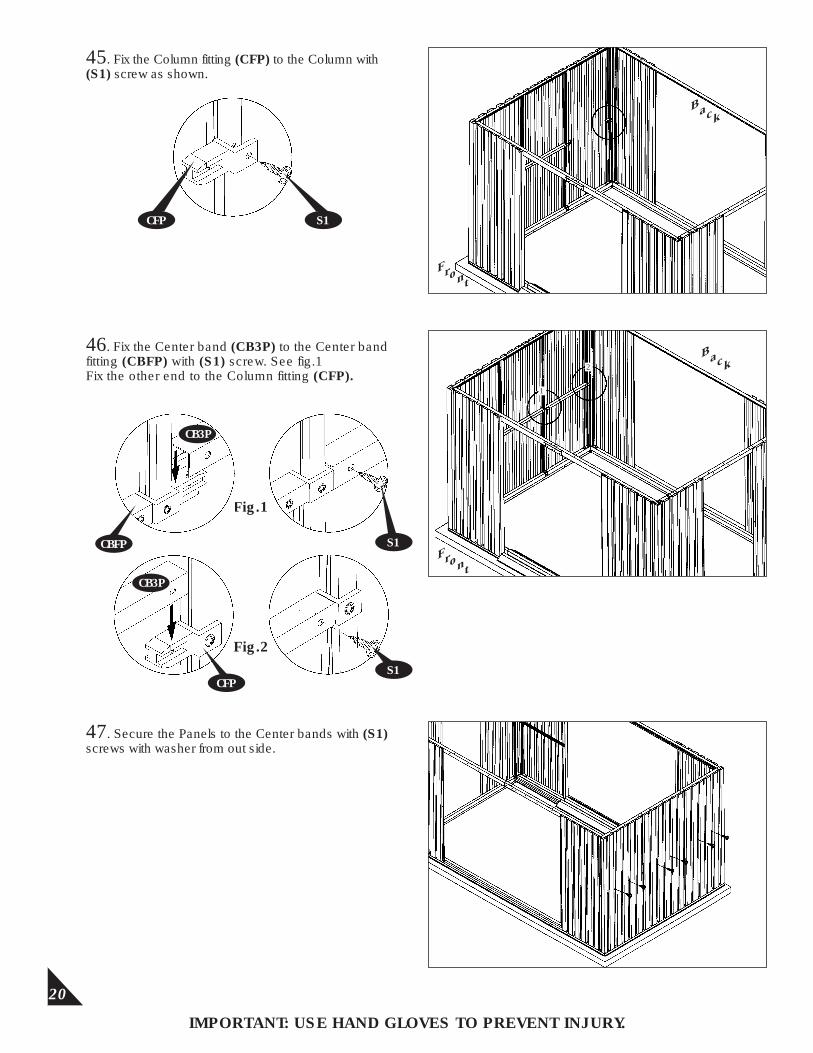
Fig.1
Fig.2
20
46. Fix the Center band (CB3P) to the Center band fitting (CBFP) with (S1) screw. See fig.1Fix the other end to the Column fitting (CFP).
47. Secure the Panels to the Center bands with (S1) screws with washer from out side.
IMPORTANT: USE HAND GLOVES TO PREVENT INJURY.
45. Fix the Column fitting (CFP) to the Column with (S1) screw as shown.
S1CFP
Front
Back
Front
Back
CBFP
CB3P
S1
CFP
CB3P
S1
1
2
21
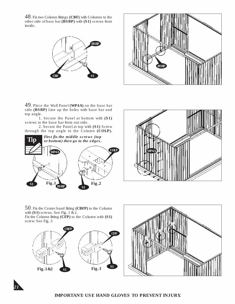
48. Fix two Column fittings (CBF) with Columns to the other side of base bar (BSBP) with (S1) screws from inside.
49. Place the Wall Panel (WP4A) on the base bar side (BSBP) Line up the holes with base bar and top angle.
1. Secure the Panel at bottom with (S1) screws to the base bar from out side.
2. Secure the Panel at top with (S1) Screw through the top angle to the Column (COLP).
50. Fix the Center band fitting (CBFP) to the Column with (S1) screws. See Fig. 1 & 2.Fix the Column fitting (CFP) to the Column with (S1) screw. See Fig. 3
IMPORTANT: USE HAND GLOVES TO PREVENT INJURY.
S1CBF
S1
WP4A
2
3
Fig.1
Fig.1&2 Fig.3S1
CFP
S1
CBFP
1
BSBP
BSBP
WP4A
1
2
S1
COLP
Fig.2BSBP
First fix the middle screws (top or bottom) then go to the edges.Tip
22
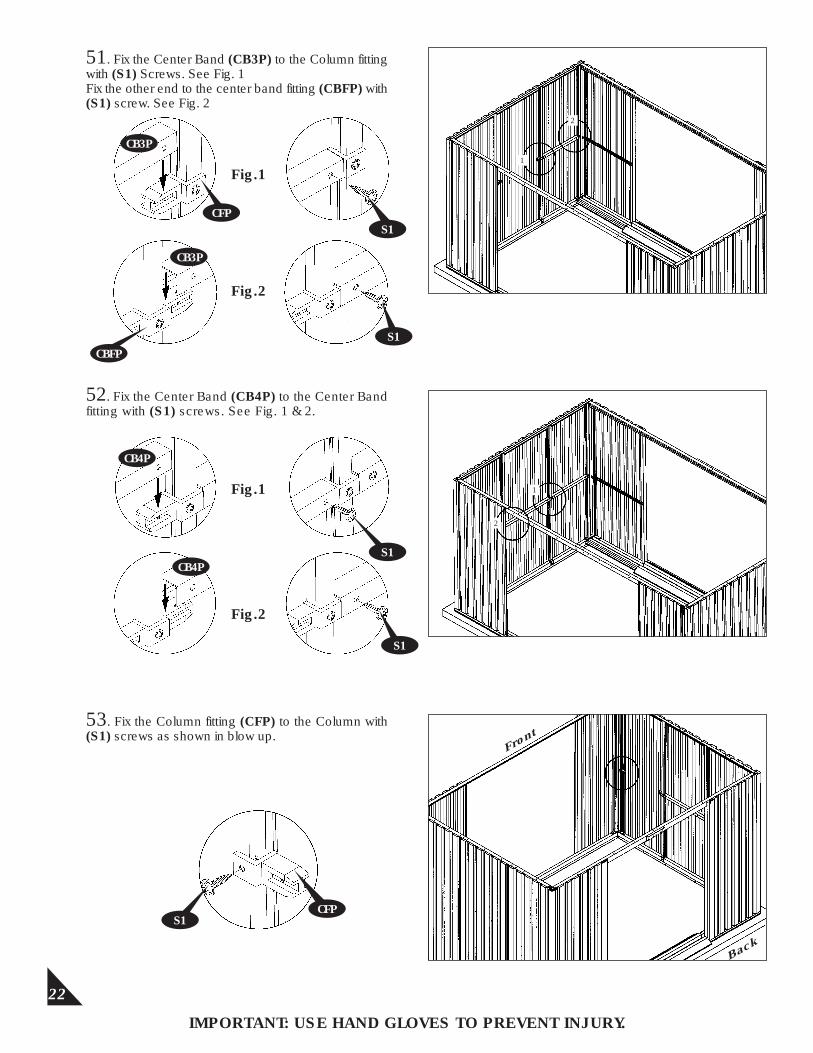
51. Fix the Center Band (CB3P) to the Column fitting with (S1) Screws. See Fig. 1Fix the other end to the center band fitting (CBFP) with (S1) screw. See Fig. 2
52. Fix the Center Band (CB4P) to the Center Band fitting with (S1) screws. See Fig. 1 & 2.
53. Fix the Column fitting (CFP) to the Column with (S1) screws as shown in blow up.
IMPORTANT: USE HAND GLOVES TO PREVENT INJURY.
1
2
Fig.1
1
2
CB4P
Fig.2
Fig.1
Fig.2
S1CFP
Front
Back
CB3P
CBFPS1
S1
CB4PS1
CFP
CB3P
S1
23
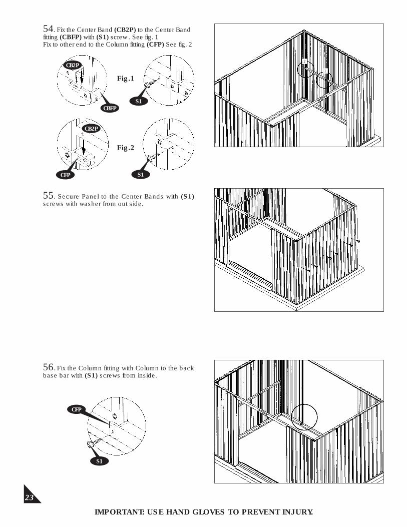
54. Fix the Center Band (CB2P) to the Center Band fitting (CBFP) with (S1) screw . See fig. 1Fix to other end to the Column fitting (CFP) See fig. 2
55. Secure Panel to the Center Bands with (S1) screws with washer from out side.
IMPORTANT: USE HAND GLOVES TO PREVENT INJURY.
56. Fix the Column fitting with Column to the back base bar with (S1) screws from inside.
1
2
Fig.2
CB2P
S1CBFP
S1
CFP
CB2P
S1
Fig.1
CFP
24
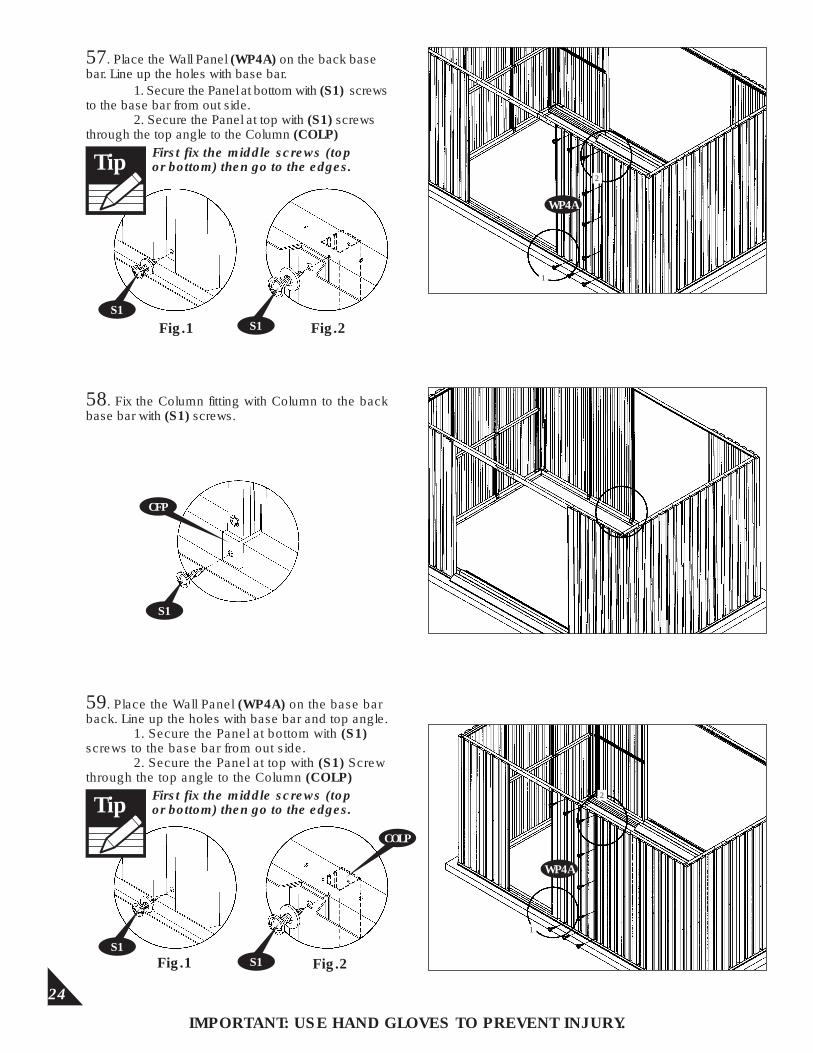
58. Fix the Column fitting with Column to the back base bar with (S1) screws.
Fig.1 Fig.2
IMPORTANT: USE HAND GLOVES TO PREVENT INJURY.
57. Place the Wall Panel (WP4A) on the back base bar. Line up the holes with base bar.
1
2
S1
Fig.2Fig.1
1. Secure the Panel at bottom with (S1) screws to the base bar from out side.
2. Secure the Panel at top with (S1) screws through the top angle to the Column (COLP)
CFP
59. Place the Wall Panel (WP4A) on the base bar back. Line up the holes with base bar and top angle.
1. Secure the Panel at bottom with (S1) screws to the base bar from out side.
2. Secure the Panel at top with (S1) Screw through the top angle to the Column (COLP)
S1S1
S1S1
COLP
1
2
WP4A
WP4A
First fix the middle screws (top or bottom) then go to the edges.Tip
First fix the middle screws (top or bottom) then go to the edges.Tip

25
60. Fix two Column fittings (CBF) with Columns to the back base bar with (S1) screws from inside.
IMPORTANT: USE HAND GLOVES TO PREVENT INJURY.
62. Fix the Center band fitting (CBFP) on the Columns with (S1) screw.
61. Place the Wall Panel (WP4A) on the base bar back. Line up the holes with base bar and top angle.
1. Secure the Panel at bottom with (S1) screws to the base bar from out side.
2. Secure the Panel at top with (S1) Screw through the top angle to the Column (COLP)
Fig.1 Fig.2
CBFP S1
1
2
S1S1
S1
S1
WP4A
First fix the middle screws (top or bottom) then go to the edges.Tip
26
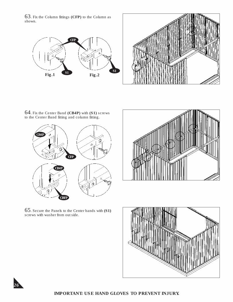
63. Fix the Column fittings (CFP) to the Column as shown.
IMPORTANT: USE HAND GLOVES TO PREVENT INJURY.
65. Secure the Panels to the Center bands with (S1) screws with washer from out side.
64. Fix the Center Band (CB4P) with (S1) screws to the Center Band fitting and column fitting.
1
2
CFP
Fig.1 Fig.2S1S1
CFP
CB4P
CB4P
CBFP
27
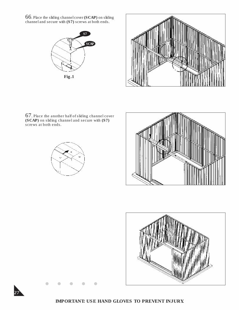
66. Place the sliding channel cover (SCAP) on sliding channel and secure with (S7) screws at both ends.
IMPORTANT: USE HAND GLOVES TO PREVENT INJURY.
67. Place the another half of sliding channel cover (SCAP) on sliding channel and secure with (S7) screws at both ends.
1
SCAP
Fig.1
S7
2
28
IMPORTANT: USE HAND GLOVES TO PREVENT INJURY.
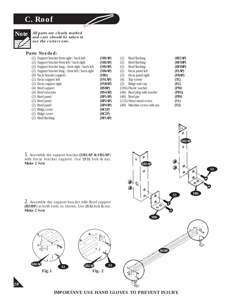
C. Roof
Parts Needed:(2) Support bracket front right / back left (SB1AP)(2) Support bracket front left / back right (SB2AP)(2) Support bracketlong - front right / back left (SB3AP)(2) Support bracket long - front left / back right (SB4AP)(8) Facia bracket support (FBS)(2) Facia support left (FSLAP)(2) Facia support right (FSRAP)(4) Roof support (RSBP)(4) Roof structure (RS4AP)(2) Roof panel (RP1AP)(2) Roof panel (RP2AP)(2) Roof panel (RP4AP)(1) Ridge cover (RC1P)(2) Ridge cover (RC2P)(2) Roof flashing (RF1AP)
All parts are clearly markedand care should be taken touse the correct one.
Note
(2) Roof flashing (RF2AP)(2) Roof flashing (RF3BP)(2) Roof flashing (RF4BP)(2) Facia panel left (FLAP)(2) Facia panel right (FRAP)(4) Top corner (TC)(2) Ridge end cap (FC)(106) Plastic washer (PW) (48) Roof plug with washer (PPG)(48) Roof pin (PIN)(132) Sheet metal screw (S1)(48) Machine screw with nut (S3)
1. Assemble the support bracket (SB1AP & SB2AP) with Facia bracket support. Use (S3) bolt & nut.Make 2 Sets
2. Assemble the support bracket with Roof support (RSBP) at both ends as shown. Use (S3) bolt & nut.Make 2 Sets
S3Fig.1
SB1AP SB2AP
Fig. 2
SB2AP
SB1AP
S3
FBS
FBS
S3
RSBP
S3
29
IMPORTANT: USE HAND GLOVES TO PREVENT INJURY.
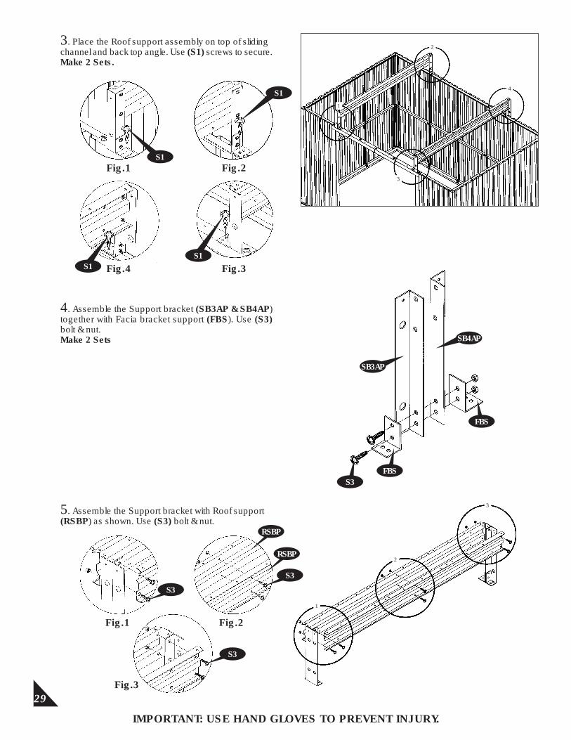
3. Place the Roof support assembly on top of sliding channel and back top angle. Use (S1) screws to secure.Make 2 Sets.
1
3
4
4. Assemble the Support bracket (SB3AP & SB4AP) together with Facia bracket support (FBS). Use (S3) bolt & nut.Make 2 Sets
SB3AP
SB4AP
S3FBS
5. Assemble the Support bracket with Roof support (RSBP) as shown. Use (S3) bolt & nut.
2
S1Fig.1 Fig.2
S1
Fig.4 Fig.3S1S1
FBS
S3
Fig.1
S3
RSBP
RSBP
Fig.2
Fig.3
S3
1
2
3
30
IMPORTANT: USE HAND GLOVES TO PREVENT INJURY.
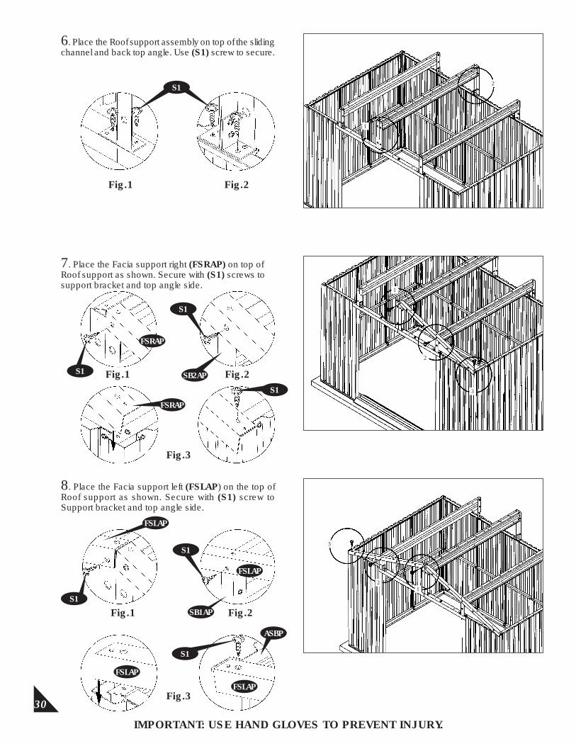
6. Place the Roof support assembly on top of the sliding channel and back top angle. Use (S1) screw to secure.
1
2
Fig.1 Fig.2
7. Place the Facia support right (FSRAP) on top of Roof support as shown. Secure with (S1) screws to support bracket and top angle side.
1
2
8. Place the Facia support left (FSLAP) on the top of Roof support as shown. Secure with (S1) screw to Support bracket and top angle side.
3
FSLAP
S1
FSRAP
Fig.3
S1
Fig.1 Fig.2S1
FSRAP
S1
SB2AP
S1
Fig.1
FSLAP
FSLAP
ASBP
S1
Fig.3
FSLAP
S1
SB1AP Fig.2
3
21
31
IMPORTANT: USE HAND GLOVES TO PREVENT INJURY.
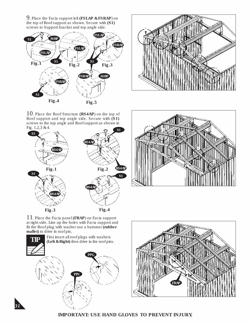
9. Place the Facia support left (FSLAP & FSRAP) on the top of Roof support as shown. Secure with (S1) screws to Support bracket and top angle side.
FSLAP
S1
1
2
3
4
5
FSLAP
FSLAPASBP
FSRAP
FSRAP
FSRAP ASBP
Fig.1 Fig.2 Fig.3
Fig.4 Fig.5
10. Place the Roof Structure (RS4AP) on the top of Roof support and top angle side. Secure with (S1) screws to the top angle and Roof support as shown in Fig. 1,2,3 & 4.
Fig.1 Fig.2
Fig.3 Fig.4
RS4AP
RS4AP
S1
11. Place the Facia panel (FRAP) on Facia support at right side. Line up the holes with Facia support and fix the Roof plug with washer use a hammer (rubber mallet) to drive in roof pin.
FRAP
S1 S1
S1
S1
RS4AP
S1
S1
RS4AP
RS4AP
1
32
3
4
PPG
TIP First insert all roof plugs with washers (Left & Right) then drive in the roof pins.
PIN

12. Place the Facia panel (FLAP) at left side and continue the same.
32
IMPORTANT: USE HAND GLOVES TO PREVENT INJURY.
13. Place the Facia panel (FLAP) on back side left facia support and fix the Roof plugs with washer and drive in roof pins.
14. Place the Facia panel (FRAP) on back side right Facia support and fix the roof plugs with washer and drive in roof pins.
FLAP
FLAP
FRAP
33
IMPORTANT: USE HAND GLOVES TO PREVENT INJURY.
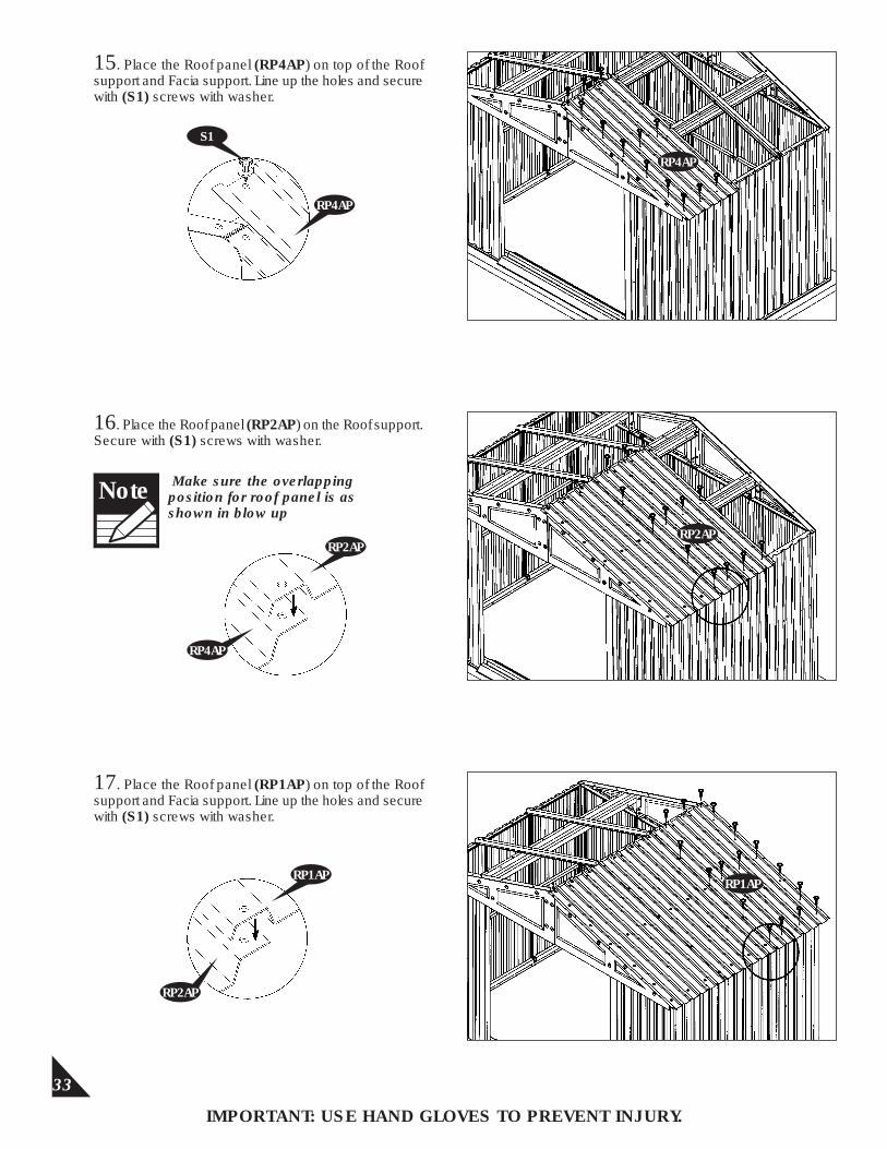
15. Place the Roof panel (RP4AP) on top of the Roof support and Facia support. Line up the holes and secure with (S1) screws with washer.
RP2AP
RP4AP
16. Place the Roof panel (RP2AP) on the Roof support. Secure with (S1) screws with washer.
S1
RP4AP
17. Place the Roof panel (RP1AP) on top of the Roof support and Facia support. Line up the holes and secure with (S1) screws with washer.
RP1AP
RP2AP
Note Make sure the overlapping position for roof panel is as shown in blow up
RP4AP
RP2AP
RP1AP
34
IMPORTANT: USE HAND GLOVES TO PREVENT INJURY.
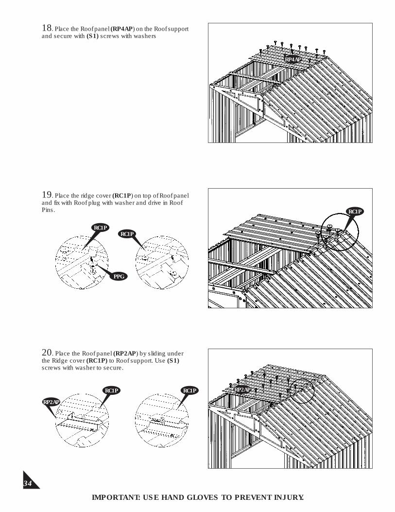
18. Place the Roof panel (RP4AP) on the Roof support and secure with (S1) screws with washers
19. Place the ridge cover (RC1P) on top of Roof panel and fix with Roof plug with washer and drive in Roof Pins.
20. Place the Roof panel (RP2AP) by sliding under the Ridge cover (RC1P) to Roof support. Use (S1) screws with washer to secure.
RP4AP
RC1P
RC1P
PPG
RC1P
RC1P
RP2AP
RC1P RP2AP
35
IMPORTANT: USE HAND GLOVES TO PREVENT INJURY.
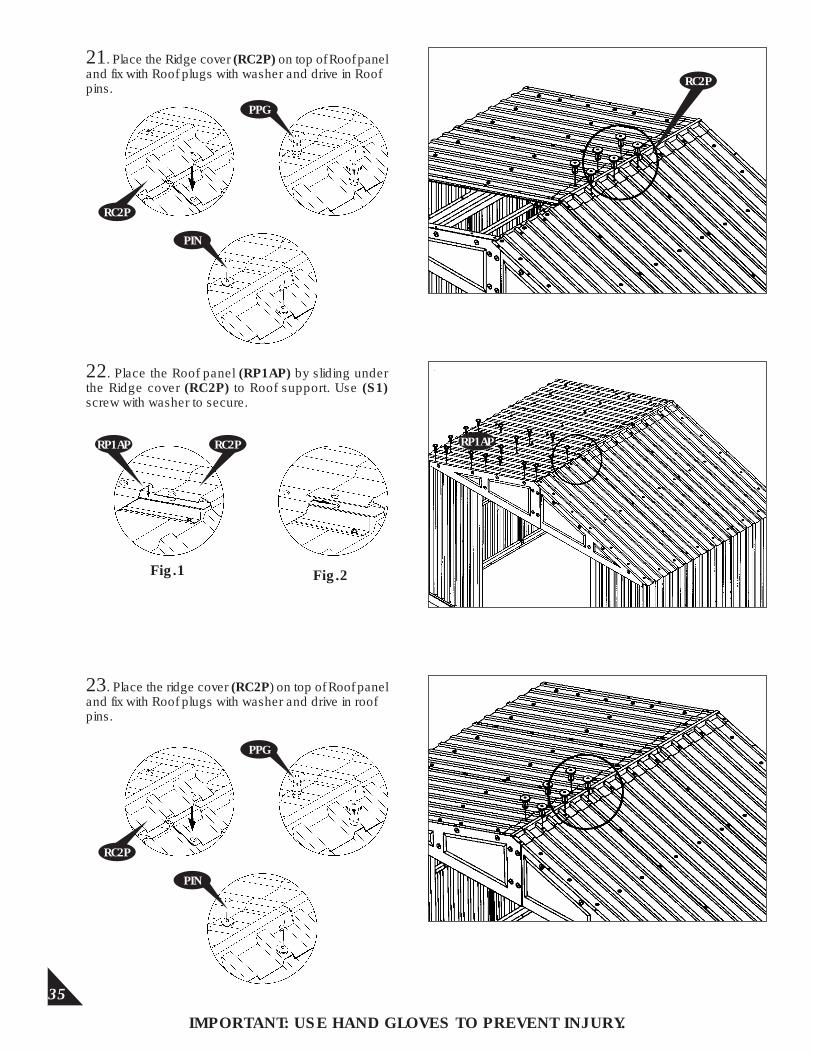
21. Place the Ridge cover (RC2P) on top of Roof panel and fix with Roof plugs with washer and drive in Roof pins.
22. Place the Roof panel (RP1AP) by sliding under the Ridge cover (RC2P) to Roof support. Use (S1) screw with washer to secure.
23. Place the ridge cover (RC2P) on top of Roof panel and fix with Roof plugs with washer and drive in roof pins.
Fig.1 Fig.2
RC2P
PPG
PIN
RC2P
RP1AP RC2P RP1AP
RC2P
PPG
PIN
36
IMPORTANT: USE HAND GLOVES TO PREVENT INJURY.
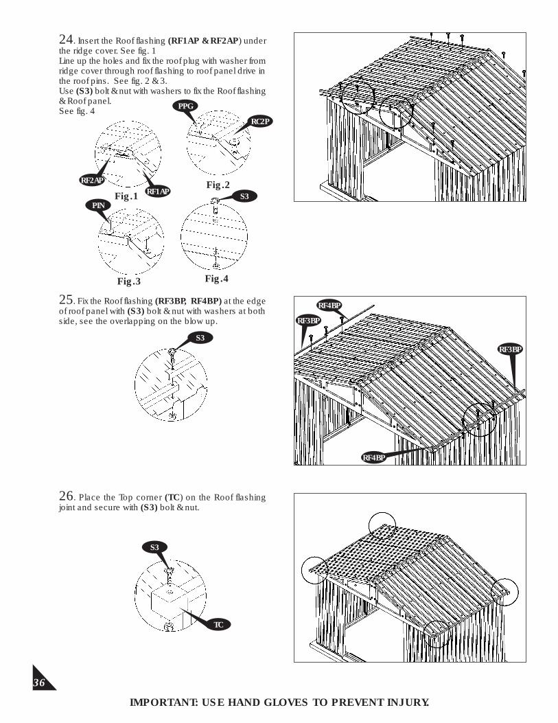
24. Insert the Roof flashing (RF1AP & RF2AP) under the ridge cover. See fig. 1Line up the holes and fix the roof plug with washer from ridge cover through roof flashing to roof panel drive in the roof pins. See fig. 2 & 3.Use (S3) bolt & nut with washers to fix the Roof flashing & Roof panel.See fig. 4
Fig.2
Fig.4
25. Fix the Roof flashing (RF3BP, RF4BP) at the edge of roof panel with (S3) bolt & nut with washers at both side, see the overlapping on the blow up.
26. Place the Top corner (TC) on the Roof flashing joint and secure with (S3) bolt & nut.
Fig.3
Fig.1 RF1AP
RF3BP
RF3BP
RF4BP
S3
TC
RF4BP
RF2AP
PINS3
RC2P
PPG
S3
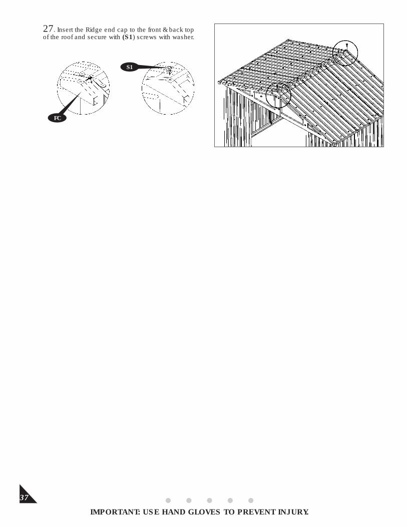
27. Insert the Ridge end cap to the front & back top of the roof and secure with (S1) screws with washer.
37
IMPORTANT: USE HAND GLOVES TO PREVENT INJURY.
FC
S1
38
IMPORTANT: USE HAND GLOVES TO PREVENT INJURY.
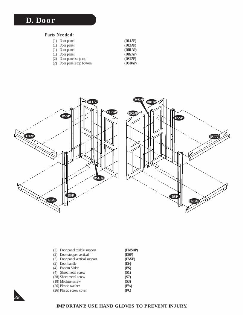
D. Door
(1) Door panel (DL1AP)(1) Door panel (DL2AP)(1) Door panel (DR1AP)(1) Door panel (DR2AP)(2) Door panel strip top (DSTAP) (2) Door panel strip bottom (DSBAP)
Parts Needed:
DSTAP
(2) Door panel middle support (DMSAP)(2) Door stopper vertical (DSP)(2) Door panel vertical support (DVSP)(2) Door handle (DH)(4) Bottom Slider (BS)(4) Sheet metal screw (S1)(38) Sheet metal screw (S7)(18) Machine screw (S3)(26) Plastic washer (PW)(26) Plastic screw cover (PC)
DVSP
DL1AP
DMSAP
DL2AP DR2AP
DR1APDMSAP
DVSP
DSTAP
DSBAPDSP
DSBAPDSP
39
IMPORTANT: USE HAND GLOVES TO PREVENT INJURY.
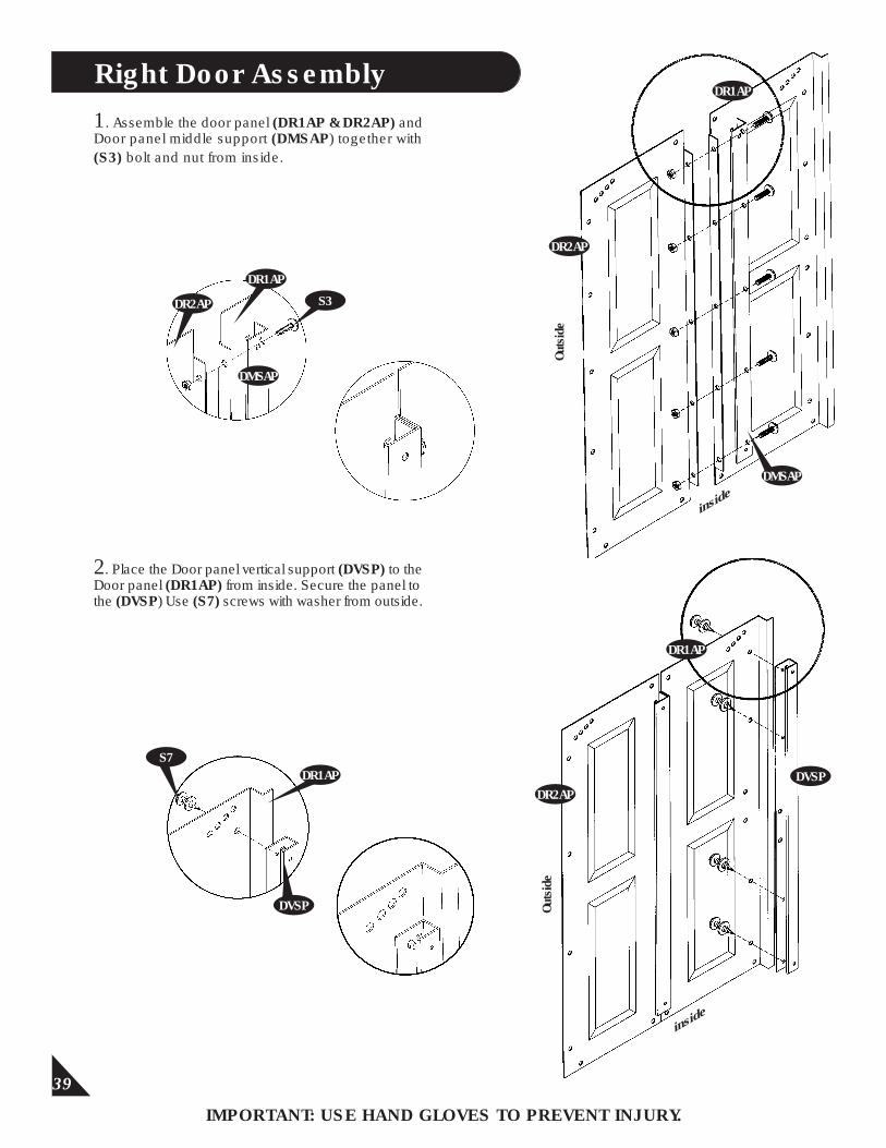
1. Assemble the door panel (DR1AP & DR2AP) and Door panel middle support (DMSAP) together with (S3) bolt and nut from inside.
Right Door Assembly
DR2AP
DR1AP
DMSAP
S3
2. Place the Door panel vertical support (DVSP) to the Door panel (DR1AP) from inside. Secure the panel to the (DVSP) Use (S7) screws with washer from outside.
DR2AP
DR1AP
Outs
ide
inside
S7
DVSP Outs
ide
inside
DR2AP
DR1AP
DVSP
DMSAP
DR1AP
40
IMPORTANT: USE HAND GLOVES TO PREVENT INJURY.
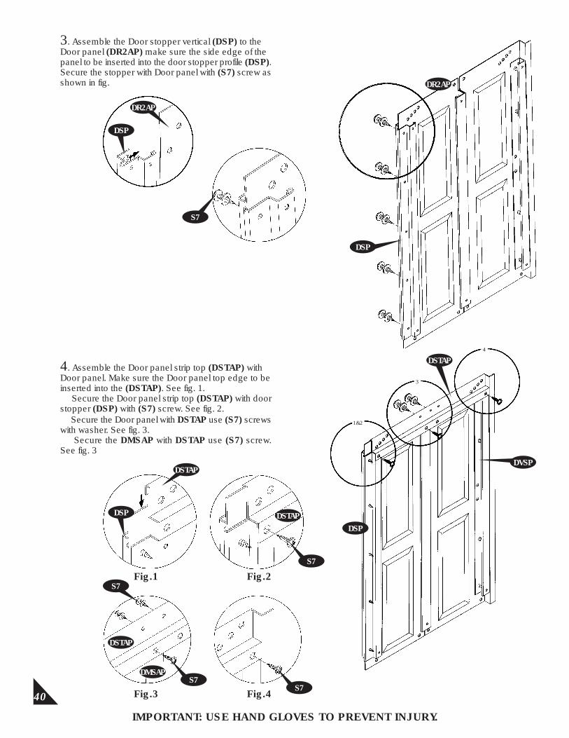
3. Assemble the Door stopper vertical (DSP) to the Door panel (DR2AP) make sure the side edge of the panel to be inserted into the door stopper profile (DSP). Secure the stopper with Door panel with (S7) screw as shown in fig.
DSP
DR2AP
S7
4. Assemble the Door panel strip top (DSTAP) with Door panel. Make sure the Door panel top edge to be inserted into the (DSTAP). See fig. 1. Secure the Door panel strip top (DSTAP) with door stopper (DSP) with (S7) screw. See fig. 2. Secure the Door panel with DSTAP use (S7) screws with washer. See fig. 3. Secure the DMSAP with DSTAP use (S7) screw. See fig. 3
DSP
DSTAP
Fig.1 Fig.2
DSTAP
S7
Fig.3 Fig.4
S7
DSTAP
S7DMSAP
DR2AP
DSP
1&2
3
4
DSTAP
DSP
S7
DVSP
41
IMPORTANT: USE HAND GLOVES TO PREVENT INJURY.
Fig.1
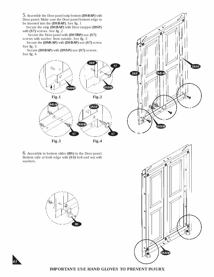
5. Assemble the Door panel strip bottom (DSBAP) with Door panel. Make sure the Door panel bottom edge to be inserted into the (DSBAP). See fig. 1 Secure the strip (DSBAP) with Door stopper (DSP) with (S7) screws. See fig. 2 Secure the Door panel with (DSTBP) use (S7) screws with washer from outside. See fig. 3 Secure the (DMSAP) with (DSBAP) use (S7) screw. See fig. 3. Secure (DSBAP) with (DVSP) use (S7) screws.See fig. 4
Fig.2
Fig.3 Fig.4
6. Assemble to bottom slider (BS) to the Door panel. Bottom side at both edge with (S3) bolt and nut with washers.
BS
DMSAP
DSP DMSAP
DSBAP
1&2
DSBAP
DVSP
DSBAP
DSBAP
DSPS7
DSBAP
S7
3
4
S7
DVSP

42
IMPORTANT: USE HAND GLOVES TO PREVENT INJURY.
7. Fix the Door handle (DH) with Door panel from front side with bolt & nut.
Left Door Assembly
8. Assemble the door panel (DL1AP & DL2AP) and Door panel middle support (DMSAP) together with (S3) bolt and nut from inside.
DMSAP
DL1AP
DMSAP
DL2AP
DL1AP
DL2AP
DMSAP
S3
DH
43
IMPORTANT: USE HAND GLOVES TO PREVENT INJURY.
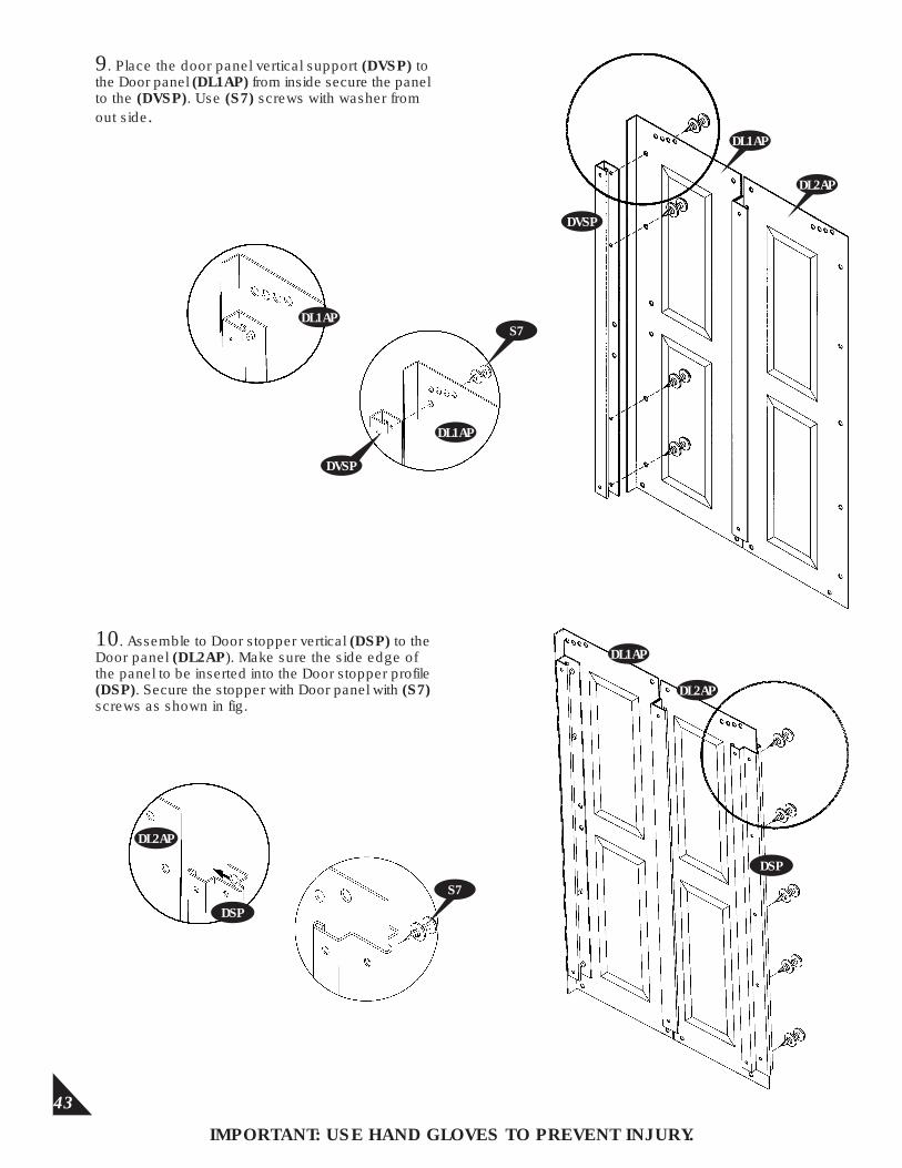
9. Place the door panel vertical support (DVSP) to the Door panel (DL1AP) from inside secure the panel to the (DVSP). Use (S7) screws with washer from out side.
DL1AP
DL1AP
DVSP
S7
10. Assemble to Door stopper vertical (DSP) to the Door panel (DL2AP). Make sure the side edge of the panel to be inserted into the Door stopper profile (DSP). Secure the stopper with Door panel with (S7) screws as shown in fig.
DL2AP
DSP
S7
DVSP
DL1AP
DL2AP
DL1AP
DL2AP
DSP
44
IMPORTANT: USE HAND GLOVES TO PREVENT INJURY.
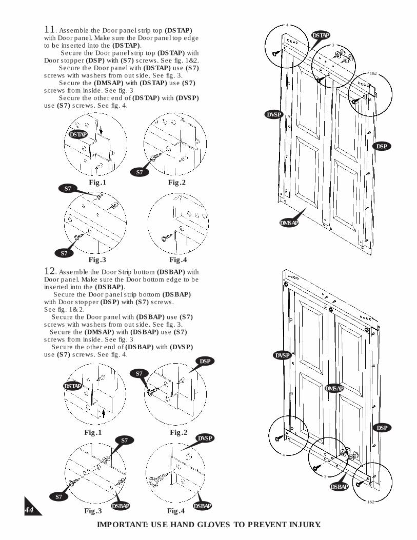
11. Assemble the Door panel strip top (DSTAP) with Door panel. Make sure the Door panel top edge to be inserted into the (DSTAP). Secure the Door panel strip top (DSTAP) with Door stopper (DSP) with (S7) screws. See fig. 1&2. Secure the Door panel with (DSTAP) use (S7) screws with washers from out side. See fig. 3. Secure the (DMSAP) with (DSTAP) use (S7) screws from inside. See fig. 3 Secure the other end of (DSTAP) with (DVSP) use (S7) screws. See fig. 4.
DSTAP
Fig.1 Fig.2S7
Fig.3 Fig.4
S7
S7
12. Assemble the Door Strip bottom (DSBAP) with Door panel. Make sure the Door bottom edge to be inserted into the (DSBAP). Secure the Door panel strip bottom (DSBAP) with Door stopper (DSP) with (S7) screws.See fig. 1& 2. Secure the Door panel with (DSBAP) use (S7) screws with washers from out side. See fig. 3. Secure the (DMSAP) with (DSBAP) use (S7) screws from inside. See fig. 3 Secure the other end of (DSBAP) with (DVSP) use (S7) screws. See fig. 4.
DSTAP
Fig.1 Fig.2
S7
Fig.3 Fig.4
S7
S7
DSTAP
DSBAP DSBAP
DSP
DMSAP
DVSP
DSP
DSBAP
4
3
1&2
DVSP
DSTAP
DVSP
DSP
DMSAP
1&2
3
4
45
IMPORTANT: USE HAND GLOVES TO PREVENT INJURY.
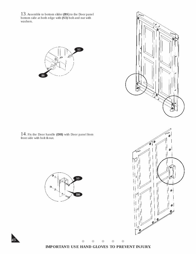
13. Assemble to bottom slider (BS) to the Door panel bottom side at both edge with (S3) bolt and nut with washers.
14. Fix the Door handle (DH) with Door panel from front side with bolt & nut.
S3
S3
BS
DH
46
IMPORTANT: USE HAND GLOVES TO PREVENT INJURY.
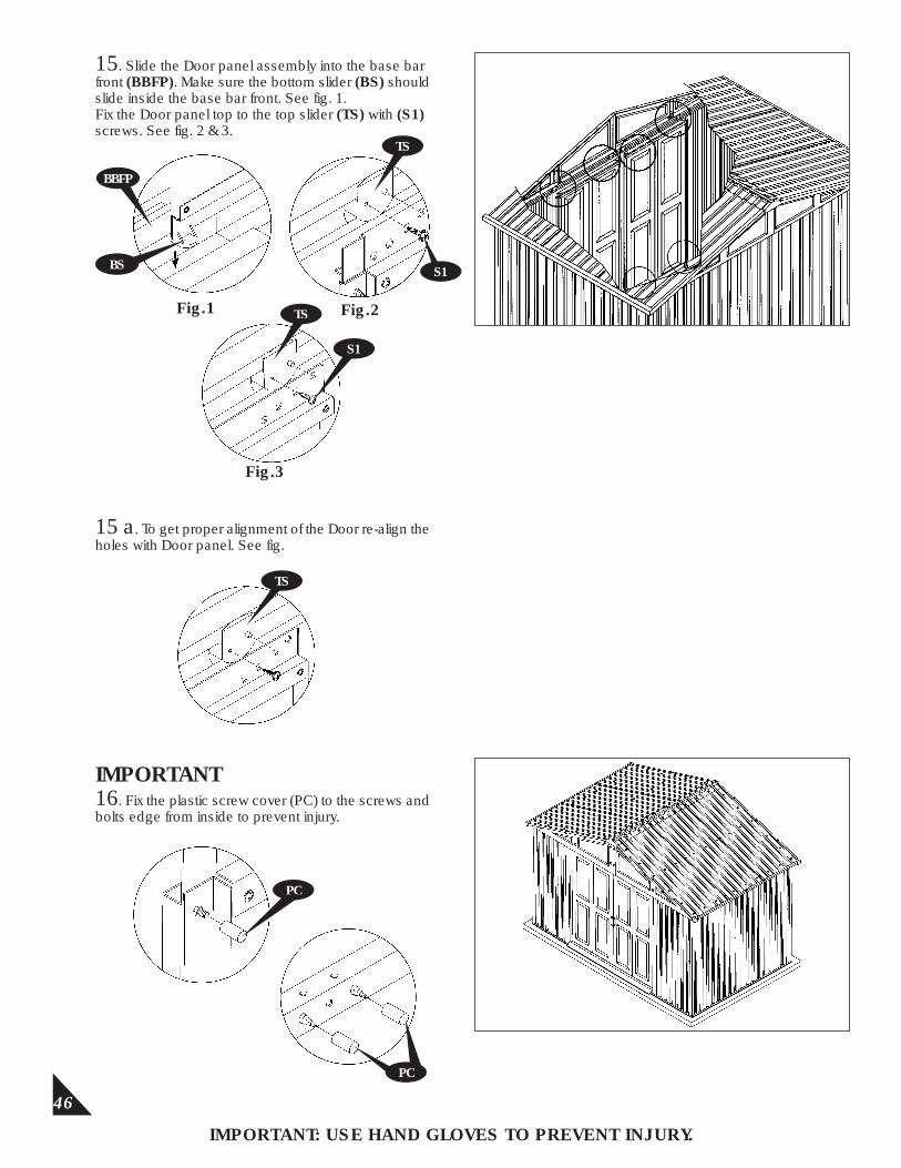
15. Slide the Door panel assembly into the base bar front (BBFP). Make sure the bottom slider (BS) should slide inside the base bar front. See fig. 1.Fix the Door panel top to the top slider (TS) with (S1) screws. See fig. 2 & 3.
BS
BBFP
15 a. To get proper alignment of the Door re-align the holes with Door panel. See fig.
IMPORTANT16. Fix the plastic screw cover (PC) to the screws and bolts edge from inside to prevent injury.
PC
PC
Fig.1
S1
TS Fig.2
Fig.3
S1
TS
TS
47
IMPORTANT: USE HAND GLOVES TO PREVENT INJURY.
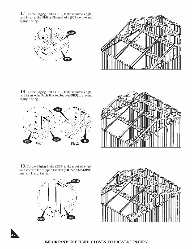
17. Cut the Edging Profile (EDP) to the required length and insert to the Sliding Channel joint (SJP) to prevent injury. See fig.
SJP
EDP
18. Cut the Edging Profile (EDP) to the required length and insert to the Facia Bracket Support (FBS) to prevent injury. See fig.
EDP
1
1
1
12
2
Fig.1 Fig.2FBS EDP
FBS
19. Cut the Edging Profile (EDP) to the required length and insert to the Support Bracket (SB3AP & SB4AP)to prevent injury. See fig.
EDPSB3AP
SB4AP