All Terrain Storage Surfboard Carts - Cal Poly
95
i | Page All Terrain Storage Surfboard Carts Team Members Roberto Gonzalez [email protected] Ben Kennedy [email protected] Danny Riedeman [email protected] Sponsor AmpSurf – Jim Stitt [email protected] Advisor Dr. Brian Self [email protected]
Transcript of All Terrain Storage Surfboard Carts - Cal Poly
i | P a g e
All Terrain Storage Surfboard
Carts
Team Members
Roberto Gonzalez [email protected]
Ben Kennedy [email protected]
Danny Riedeman [email protected]
Sponsor
AmpSurf – Jim Stitt [email protected]
Advisor
Dr. Brian Self [email protected]
ii | P a g e
Mechanical Engineering Department
California Polytechnic State University
Table of Contents
Executive Summary ................................................................................................................................ 1
1 Introduction ..................................................................................................................................... 2
2 Background 2
2.1 Interview .................................................................................................................................. 2
2.2 Research .................................................................................................................................. 3
3 Objectives 8
3.1 Problem Statement ................................................................................................................... 8
3.2 Customer Needs & Wants ........................................................................................................ 8
3.3 Quality Function Deployment House of Quality ....................................................................... 9
3.4 Engineering Specifications ....................................................................................................... 9
4 Concept Design Development .......................................................................................................... 9
4.1 Concept Development Process & Results ................................................................................. 9
4.2 Concept Selection Process & Results ...................................................................................... 10
4.3 Preliminary Analysis .............................................................................................................. 14
4.4 Detailed Description of Design ............................................................................................... 14
4.5 Concept Functionality ............................................................................................................ 17
4.6 Challenges ............................................................................................................................. 17
5 Final Design .................................................................................................................................. 17
5.1 Overall description & layout .................................................................................................. 17
5.2 Analysis description & results ................................................................................................ 21
5.3 Material Selection .................................................................................................................. 23
5.4 Cost Analysis ......................................................................................................................... 24
5.5 Safety, maintenance, & repair considerations (updated FMEA) .............................................. 25
6 Manufacturing ............................................................................................................................... 25
6.1 Detailed Manufacturing Description ....................................................................................... 25
6.2 Manufacturing Challenges ...................................................................................................... 28
7 Design Verification Plan ................................................................................................................ 28
8 Project Management ...................................................................................................................... 31
9 Conclusion & Recommendations ................................................................................................... 32
10 References 33
iii | P a g e
Appendix A. Customer Wants/Needs ............................................................................................... 34
Appendix B. QFD House of Quality ................................................................................................ 35
Appendix C. Decision Matrices ....................................................................................................... 36
Appendix D. Trailer Layout ............................................................................................................. 38
Appendix E. Complete Drawing Package ........................................................................................ 40
Appendix F. Safety Hazard Checklist .............................................................................................. 75
Appendix G. Gantt Chart ................................................................................................................. 76
Appendix H. DVPR ......................................................................................................................... 77
Appendix I. Beam in Bending Stress Calculations .......................................................................... 78
Appendix J. Material Selection ....................................................................................................... 81
Appendix K. Cost Analysis .............................................................................................................. 87
Appendix L. Failure Modes & Effects Analysis ............................................................................... 88
Appendix M. Operators’ Manual ...................................................................................................... 89
1 | P a g e
Executive Summary All Terrain Storage consists of three mechanical engineering students: Roberto Gonzalez, Ben Kennedy,
and Danny Riedeman. The goal of All Terrain Storage is to design and create two portable storage
devices for the non-profit organization AmpSurf. AmpSurf helps veterans, people with disabilities, and
anyone else who could be helped through adaptive surfing and other outdoor activities. Their current
method of storing and transporting equipment for events is carrying it from the trailer in the parking lot
through the sand onto the beach. This document will provide: a more thorough introduction to AmpSurf
and the project, the objectives, background information, the iterative design process, manufacturing of the
final design, and final product validation.
2 | P a g e
1 Introduction
AmpSurf is a non-profit organization established to promote, inspire, educate, and rehabilitate all people
with disabilities through adaptive surfing and other outdoor activities. For the last 15 years, AmpSurf has
been providing learn-to-surf clinics to serve those in need. They have served hundreds of veterans with
disabilities as well as disabled adults and children who may never have had an opportunity to experience
the ocean in the same capacity if not for AmpSurf’s programs. AmpSurf is in need of two portable storage
devices to securely hold surfing equipment in their trailer while being driven to and from events, as well
as during transportation onto the beach. There is a strong need for the portable storage devices because
currently transporting this equipment is done by volunteers carrying pieces of equipment by hand over
long distances. We are the All Terrain Storage (ATS) team consisting of three 4th year mechanical
engineering students: Roberto Gonzalez, Ben Kennedy, and Danny Riedeman. We will use our
knowledge of the design process to safely and efficiently design and manufacture a product to solve
AmpSurf’s needs.
2 Background
AmpSurf has a large trailer filled with surf equipment for events. They need two portable storage devices,
one to hold administration boxes, pop up tarps, tables, and chairs. The second storage device will be used
store and transport 16 large surfboards and upwards of 25 wetsuits. They need to be able to traverse
pavement as well as sand conditions. This is currently accomplished by volunteers carrying the equipment
piece by piece onto the beach. The customer’s need for these products is extensive. The specific customer
needs list can be seen in more detail in the Objectives section. The most significant takeaways from our
meetings with AmpSurf’s representative, and our sponsor, Mr. Stitt, were that the gear must stay secure
while in transport and the rack should require less effort when moving the gear to the beach than their
current method of carrying all the equipment by hand. For us to fully understand the problem and help
provide an adequate solution to this problem, we met with Mr. Stitt four times.
2.1 Interview Our first meeting with Mr. Stitt was over dinner so we could become acquainted with one another and
gain an initial understanding of his perspective of this project. This meeting was very informative and
taught us a lot about AmpSurf as an organization. The passion that Mr. Stitt expressed about AmpSurf
and its participants helped us develop an emotional connection with the project and the many people it
can help. We also discussed clerical topics such as funding and expectations from both invested parties.
The only topic that was difficult to discuss was the technical constraints and specifications of the project.
To attain these technical constraints, we met up again for a second meeting at AmpSurf’s headquarters to
see their trailer in person.
AmpSurf’s headquarters is located in Pismo Beach, CA, where the trailer is stored when not at an event
and during the offseason. This meeting was focused on obtaining an inventory of the equipment the carts
must hold as well as the dimensions of all this equipment. This meeting helped us develop a better idea of
the amount of gear we are required to store and to speak with Mr. Stitt more about the possible
bottlenecks of the project. One of these possible obstacles was the transport of the cart to the beach in
Pismo because it will need to pass beneath an overpass. Seeing the path that is used in Pismo Beach was
important because it allowed us to explore any other obstacles that we may not have foreseen. Overall
3 | P a g e
these two meetings helped us develop a much more comprehensive understanding of the problem and the
potential areas for holdups when designing the cart.
2.2 Research In addition to better understanding their problem we conducted research for similar solutions that
currently exist to see how others have accomplished similar tasks.
Products that currently exist in this market are the Quiver Kaddy, Wheeleez™ Inc. SUP Rack-3, Mac
Sports Heavy Duty All Terrain Utility Beach Wagon Cart, and Wheeleez™ Inc. Beach Cart. This market
is broadly defined as a cart that is designed to carry equipment on the sand. The Quiver Kaddy and the
Wheeleez™ Inc. SUP Rack-3 are both solutions that help a surfer transport multiple, large surfboards
more easily than simply carrying the boards. The Mac Sports Beach Wagon and Wheeleez™ Inc. Beach
Cart are both wagon-like carts that allow the user to pile their miscellaneous gear on one cart that rolls
easily on the sand. These products fall into two separate categories: surfboard transport and equipment
transport, and both are considered because we will be manufacturing two carts.
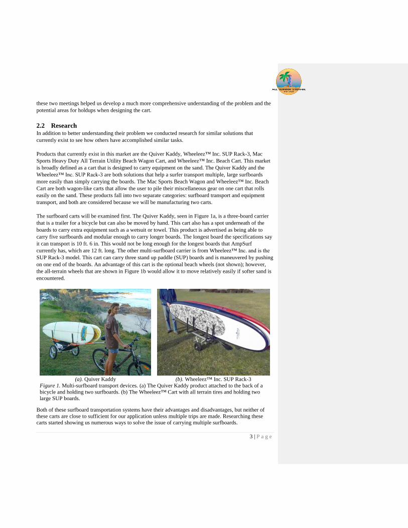
The surfboard carts will be examined first. The Quiver Kaddy, seen in Figure 1a, is a three-board carrier
that is a trailer for a bicycle but can also be moved by hand. This cart also has a spot underneath of the
boards to carry extra equipment such as a wetsuit or towel. This product is advertised as being able to
carry five surfboards and modular enough to carry longer boards. The longest board the specifications say
it can transport is 10 ft. 6 in. This would not be long enough for the longest boards that AmpSurf
currently has, which are 12 ft. long. The other multi-surfboard carrier is from Wheeleez™ Inc. and is the
SUP Rack-3 model. This cart can carry three stand up paddle (SUP) boards and is maneuvered by pushing
on one end of the boards. An advantage of this cart is the optional beach wheels (not shown); however,
the all-terrain wheels that are shown in Figure 1b would allow it to move relatively easily if softer sand is
encountered.
(a). Quiver Kaddy (b). Wheeleez™ Inc. SUP Rack-3
Figure 1. Multi-surfboard transport devices. (a) The Quiver Kaddy product attached to the back of a
bicycle and holding two surfboards. (b) The Wheeleez™ Cart with all terrain tires and holding two
large SUP boards.
Both of these surfboard transportation systems have their advantages and disadvantages, but neither of
these carts are close to sufficient for our application unless multiple trips are made. Researching these
carts started showing us numerous ways to solve the issue of carrying multiple surfboards.
4 | P a g e
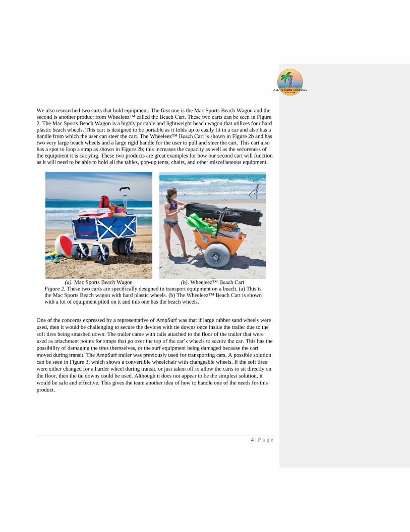
We also researched two carts that hold equipment. The first one is the Mac Sports Beach Wagon and the
second is another product from Wheeleez™ called the Beach Cart. These two carts can be seen in Figure
2. The Mac Sports Beach Wagon is a highly portable and lightweight beach wagon that utilizes four hard
plastic beach wheels. This cart is designed to be portable as it folds up to easily fit in a car and also has a
handle from which the user can steer the cart. The Wheeleez™ Beach Cart is shown in Figure 2b and has
two very large beach wheels and a large rigid handle for the user to pull and steer the cart. This cart also
has a spot to loop a strap as shown in Figure 2b; this increases the capacity as well as the secureness of
the equipment it is carrying. These two products are great examples for how our second cart will function
as it will need to be able to hold all the tables, pop-up tents, chairs, and other miscellaneous equipment.
(a). Mac Sports Beach Wagon (b). Wheeleez™ Beach Cart
Figure 2. These two carts are specifically designed to transport equipment on a beach. (a) This is
the Mac Sports Beach wagon with hard plastic wheels. (b) The Wheeleez™ Beach Cart is shown
with a lot of equipment piled on it and this one has the beach wheels.
One of the concerns expressed by a representative of AmpSurf was that if large rubber sand wheels were
used, then it would be challenging to secure the devices with tie downs once inside the trailer due to the
soft tires being smashed down. The trailer came with rails attached to the floor of the trailer that were
used as attachment points for straps that go over the top of the car’s wheels to secure the car. This has the
possibility of damaging the tires themselves, or the surf equipment being damaged because the cart
moved during transit. The AmpSurf trailer was previously used for transporting cars. A possible solution
can be seen in Figure 3, which shows a convertible wheelchair with changeable wheels. If the soft tires
were either changed for a harder wheel during transit, or just taken off to allow the carts to sit directly on
the floor, then the tie downs could be used. Although it does not appear to be the simplest solution, it
would be safe and effective. This gives the team another idea of how to handle one of the needs for this
product.

5 | P a g e
Figure 3. Portable Convertible Wheelchair (Helterbrand)
The surfboards are large and will need to be safely secured during transportation. A related solution to
this can be seen in Figure 4. The Surf Board Rack for Vehicles (Skoff) offers a simple way to secure
multiple surfboards while in transit. The racks have an elliptical base that matches that of a surfboard. The
board is inserted into this until it is snug. Then there is another half ellipse that the board sits on, where a
strap wraps around and secures it. This design takes advantage of the contours of the surfboard to secure
it. The rack securely holds the surfboards in more than just the configuration shown. This could be
incorporated or adapted to the team's future design. A design similar to this is worth investigating further
for holding the surfboards while in the trailer, or while being moved to the beach.
Figure 4. Surfboard Rack for Vehicles (Skoff).
6 | P a g e
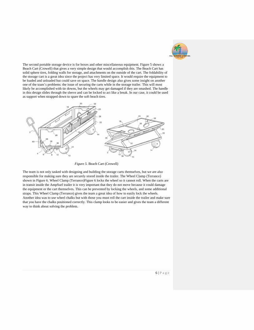
The second portable storage device is for boxes and other miscellaneous equipment. Figure 5 shows a
Beach Cart (Crowell) that gives a very simple design that would accomplish this. The Beach Cart has
solid sphere tires, folding walls for storage, and attachments on the outside of the cart. The foldability of
the storage cart is a great idea since the project has very limited space. It would require the equipment to
be loaded and unloaded but could save on space. The handle design also gives some insight on another
one of the team’s problems: the issue of securing the carts while in the storage trailer. This will most
likely be accomplished with tie downs, but the wheels may get damaged if they are smashed. The handle
in this design slides through the sleeve and can be locked to act like a break. In our case, it could be used
as support when strapped down to spare the soft beach tires.
Figure 5. Beach Cart (Crowell)
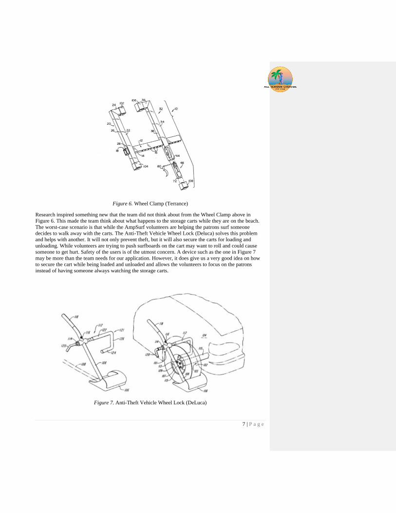
The team is not only tasked with designing and building the storage carts themselves, but we are also
responsible for making sure they are securely stored inside the trailer. The Wheel Clamp (Terrance)
shown in Figure 6. Wheel Clamp (Terrance)Figure 6 locks the wheel so it cannot roll. When the carts are
in transit inside the AmpSurf trailer it is very important that they do not move because it could damage
the equipment or the cart themselves. This can be prevented by locking the wheels, and some additional
straps. This Wheel Clamp (Terrance) gives the team a great idea of how to easily lock the wheels.
Another idea was to use wheel chalks but with those you must roll the cart inside the trailer and make sure
that you have the chalks positioned correctly. This clamp looks to be easier and gives the team a different
way to think about solving the problem.
7 | P a g e
Figure 6. Wheel Clamp (Terrance)
Research inspired something new that the team did not think about from the Wheel Clamp above in
Figure 6. This made the team think about what happens to the storage carts while they are on the beach.
The worst-case scenario is that while the AmpSurf volunteers are helping the patrons surf someone
decides to walk away with the carts. The Anti-Theft Vehicle Wheel Lock (Deluca) solves this problem
and helps with another. It will not only prevent theft, but it will also secure the carts for loading and
unloading. While volunteers are trying to push surfboards on the cart may want to roll and could cause
someone to get hurt. Safety of the users is of the utmost concern. A device such as the one in Figure 7
may be more than the team needs for our application. However, it does give us a very good idea on how
to secure the cart while being loaded and unloaded and allows the volunteers to focus on the patrons
instead of having someone always watching the storage carts.
Figure 7. Anti-Theft Vehicle Wheel Lock (DeLuca)

8 | P a g e
3 Objectives
3.1 Problem Statement AmpSurf hosts learn-to-surf events throughout the United States to help hundreds of veterans, adults and
children. At these events volunteers carry equipment, such as surfboards, wetsuits, tables, chairs, and
safety equipment, from their trailer long distances to where they set up. Multiple trips need to be made by
volunteers to carry all the equipment, which proves to be very time consuming and labor intensive. As a
result, AmpSurf has asked for two portable storage devices to securely hold all their equipment while in
the trailer and during transportation onto the sand at the beach. AmpSurf wants one portable storage
device to hold surfboards and wetsuits and a second to hold the remaining equipment. A boundary
diagram of the project is shown in Figure 8.
Figure 8. Boundary Diagram.
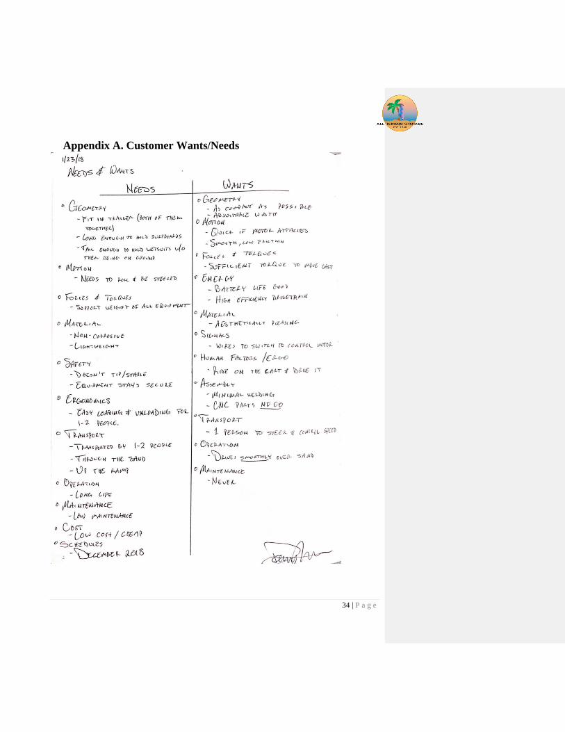
3.2 Customer Needs & Wants From our interview with Mr. Stitt we gained a better understanding of AmpSurf’s needs and wants from
these devices. Details of the final product’s performance were discussed and from this we created a list of
the customer’s needs as seen in Appendix A. This list was then refined into Table 1.
Table 1. Customer needs
1. Fits in trailer
2. Long enough to hold surfboards
3. Tall enough to hang wetsuits
4. Rolls
5. Steers
6. Support weight of equipment
7. Non-corrosive
8. Lightweight
9. Does not tip
10. Equipment stays secure
11. Easy loading & unloading
12. 1-2 people can move it
13. Easily moves on sand
14. Rolls up the ramp
15. Long life
16. Low maintenance
Commented [BMSK1]: Got up to this section with
corrections

9 | P a g e
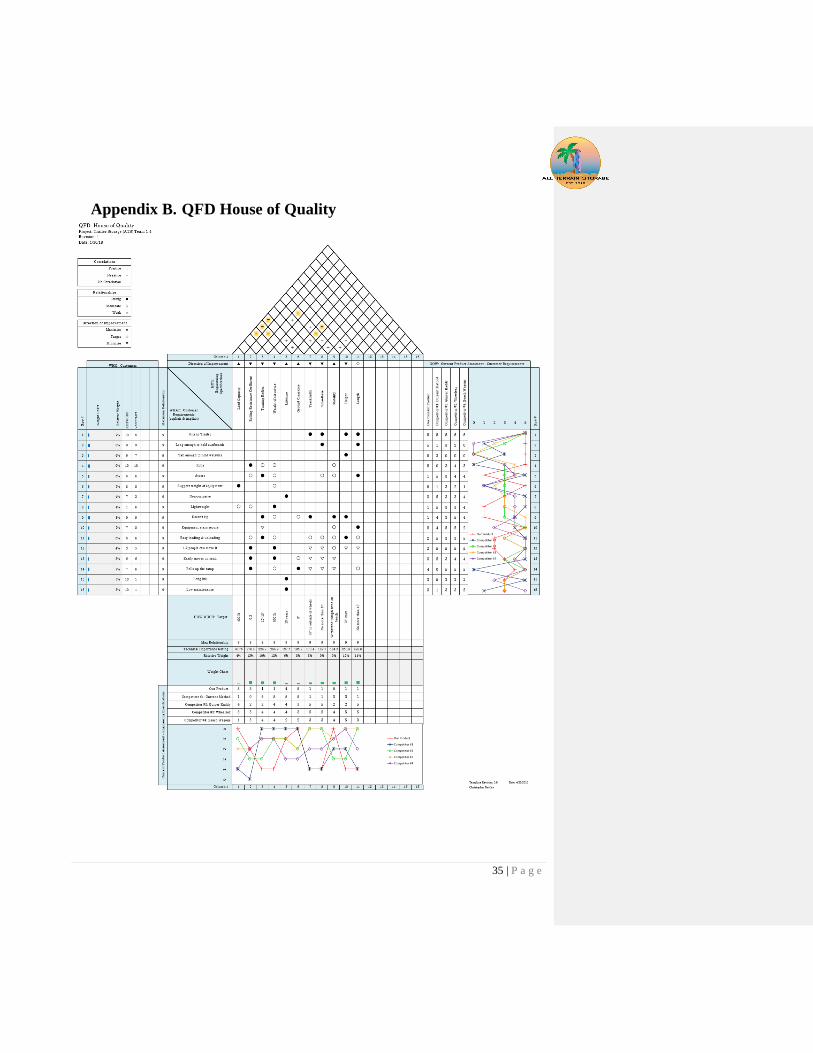
3.3 Quality Function Deployment House of Quality In order to meet as many of the customer’s needs as possible and to ensure we hit the needs that are
absolutely required, we performed a Quality Function Deployment (QFD) analysis. The QFD analysis
consisted of listing the customer wants, needs, and engineering specifications then comparing each want
and need to engineering specifications. This analysis helped us determine how the engineering
specifications affect one another and then we came to a final target for each specification. The full QFD
analysis lists our customers, customer requirements, engineering specifications, targets, and can be seen
in Appendix B.
3.4 Engineering Specifications Using our results from the QFD analysis and measurements taken from the trailer and equipment, we
were able to come to a final target for each specification which can be seen in Table 2 measurements,
such as turning radius or ground clearance, were obtained by looking at the path these portable storage
devices would have to take to reach the event set up by AmpSurf in Pismo Beach. When creating our
engineering specifications lists we wanted to ensure that every specifications target could be measured.
The compliance column is in Table 2. Along with this we have assessed the risk of each target as low,
medium, or high based on the scope of the design and the specification.
Table 2. Engineering Specification Sheet
Spec. # Specification Description Target (units) Actual Risk Compliance
1 Load Capacity 400 lb 520 lb Low A, T
2 Rolling Resistance Coefficient 0.3 Medium A, T
3 Turning Radius 12' - 15' 12’ Medium A, T
4 Weight of Structure 150 lb 70 lb Low I
5 Lifetime 10 years High A
6 Ground Clearance 8" 8” Low I
7 Track width 80" 80.5” Medium I
8 Wheelbase 5' 5’ Low I
9 Stability 20 mph wind High A, T
10 Height 78" 73” Low I
11 Combined Length of Both
Structures 20’ Low I
4 Concept Design Development
4.1 Concept Development Process & Results After completing our engineering specifications, we moved into the concept development phase. This
process began with breaking down the design needs into a few basic functions which included: the
structure, mode of transportation, and steering. The knowledge we gained through the research portion of
the project was then combined with our own ideas through a brainstorming session for each of the
functions. We performed brainwriting for the structure, followed by brainstorming for the mode of
transportation and steering. When performing all these ideation sessions it was important to not judge an
idea someone has, because even if that idea may not be feasible it could inspire a different, innovative
idea.

10 | P a g e
Ideation sessions were performed for the surfboard rack structure, mode of transportation, and steering
system. Criteria for each function had to be met, constraints included: the potential to hold the required
equipment, fitting in the trailer, and simplifying manufacturing. Concept models were then built to
explore further ideas and possibly foresee problems with the designs as shown in Figure 9. After the team
had begun to exhaust ideas our peers reviewed and offered their insights into each of the models,
specifying the advantages and disadvantages of each model. The same process was done for the steering
and mode of transportation; however, peer reviews were not done for those two functions.
Figure 9. Shape of structure concept models.
The biggest benefit of the concept models was that they allowed us to visualize the pitfalls and benefits of
each model, making the future down selection process easier. The problem we ran into was that the
models did not scale properly. Therefore, we could not get a good grasp on the sizing of the structure and
whether the equipment would in fact fit.
4.2 Concept Selection Process & Results The concept selection process for the mode of transportation and steering began with taking the most
promising idea from the brainstorming sessions and then inserting them into weighted decision matrices
as seen in Table 3 and Table 4. The factors weighted heaviest for mode of transportation were the
effectiveness over sand and asphalt, our two main surfaces. The two leading solutions after this process
were rubber beach wheels and bike wheels. Decision matrices are a great starting point, but as with any
other tool a check must be performed. The bike wheels perform very well in the ground clearance and
asphalt factors but cannot be used on the sand. Therefore, they were eliminated as a potential solution.
Table 4 shows the decision matrix for steering. The factors weighted heaviest were ergonomics and
durability. Ergonomics in this case is synonymous with ease of use. AmpSurf as stated before is a non-
profit and run by volunteers; therefore, it is crucial for the final design to be user friendly. The top
candidates for the steering mechanism were caster wheels and a rotating axle with a bushing. Again, it
was vital to check if these were viable. When investigated further the caster wheels, which were by far the
leading candidate, did not perform well in the sand. The most concerning movement is when the user
needs to reverse directions; the caster wheels have a tendency to dig into the sand and get stuck.
Commented [BMSK2]: Do we want to attach this?
11 | P a g e
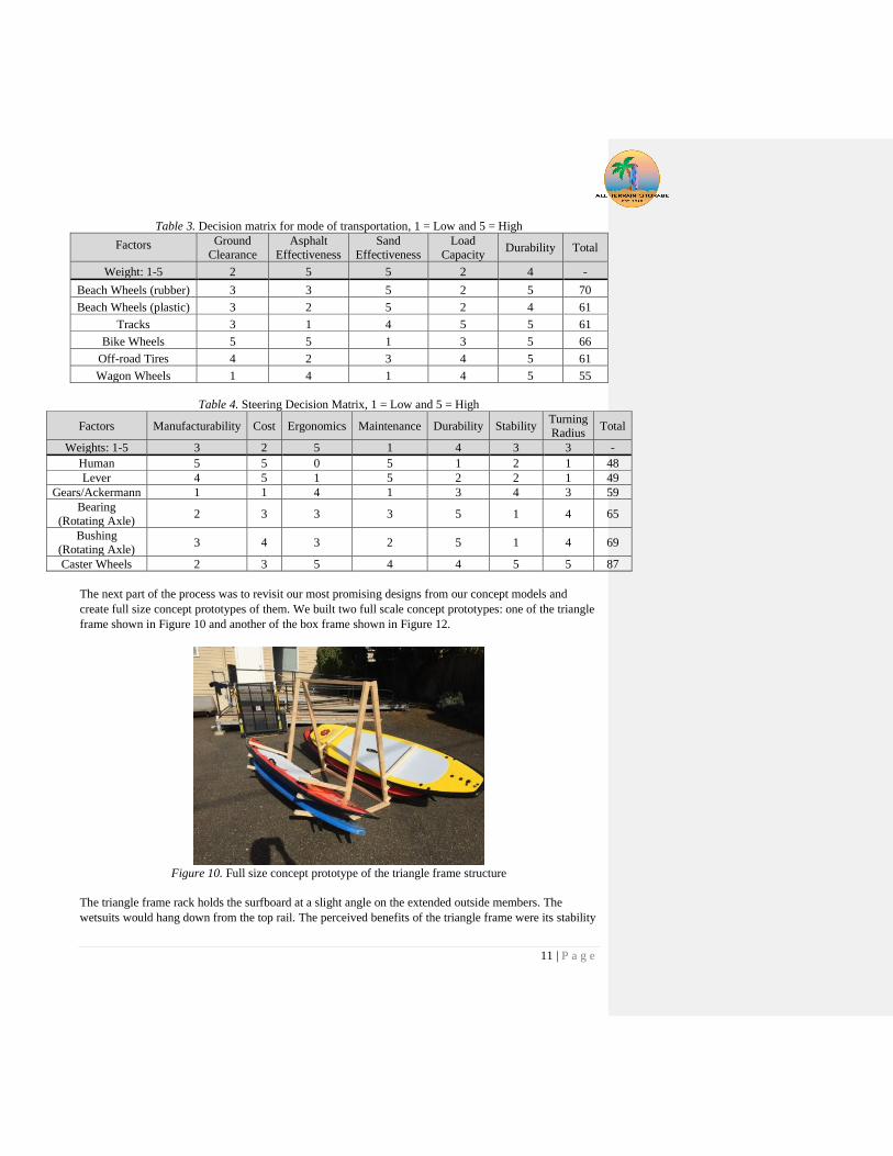
Table 3. Decision matrix for mode of transportation, 1 = Low and 5 = High
Factors Ground
Clearance
Asphalt
Effectiveness
Sand
Effectiveness
Load
Capacity Durability Total
Weight: 1-5 2 5 5 2 4 -
Beach Wheels (rubber) 3 3 5 2 5 70
Beach Wheels (plastic) 3 2 5 2 4 61
Tracks 3 1 4 5 5 61
Bike Wheels 5 5 1 3 5 66
Off-road Tires 4 2 3 4 5 61
Wagon Wheels 1 4 1 4 5 55
Table 4. Steering Decision Matrix, 1 = Low and 5 = High
Factors Manufacturability Cost Ergonomics Maintenance Durability Stability Turning
Radius Total
Weights: 1-5 3 2 5 1 4 3 3 -
Human 5 5 0 5 1 2 1 48
Lever 4 5 1 5 2 2 1 49
Gears/Ackermann 1 1 4 1 3 4 3 59
Bearing
(Rotating Axle) 2 3 3 3 5 1 4 65
Bushing
(Rotating Axle) 3 4 3 2 5 1 4 69
Caster Wheels 2 3 5 4 4 5 5 87
The next part of the process was to revisit our most promising designs from our concept models and
create full size concept prototypes of them. We built two full scale concept prototypes: one of the triangle
frame shown in Figure 10 and another of the box frame shown in Figure 12.
Figure 10. Full size concept prototype of the triangle frame structure
The triangle frame rack holds the surfboard at a slight angle on the extended outside members. The
wetsuits would hang down from the top rail. The perceived benefits of the triangle frame were its stability
12 | P a g e
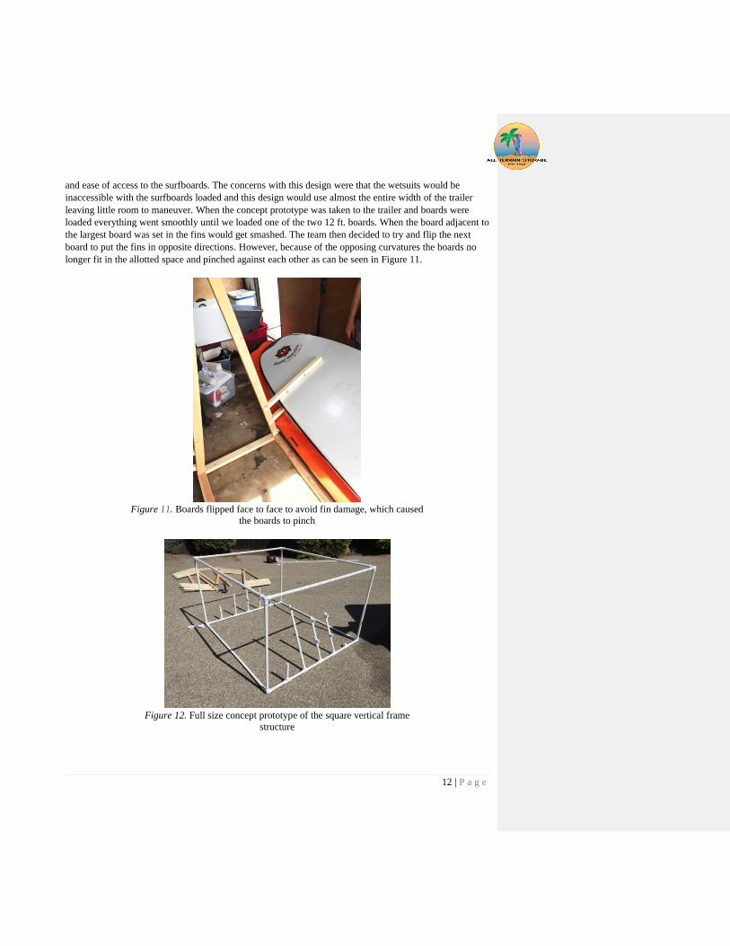
and ease of access to the surfboards. The concerns with this design were that the wetsuits would be
inaccessible with the surfboards loaded and this design would use almost the entire width of the trailer
leaving little room to maneuver. When the concept prototype was taken to the trailer and boards were
loaded everything went smoothly until we loaded one of the two 12 ft. boards. When the board adjacent to
the largest board was set in the fins would get smashed. The team then decided to try and flip the next
board to put the fins in opposite directions. However, because of the opposing curvatures the boards no
longer fit in the allotted space and pinched against each other as can be seen in Figure 11.
Figure 11. Boards flipped face to face to avoid fin damage, which caused
the boards to pinch
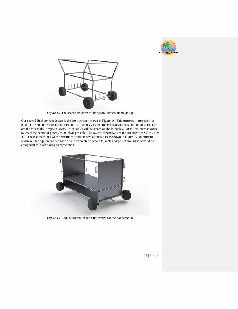
Figure 12. Full size concept prototype of the square vertical frame
structure

13 | P a g e
The box frame prototype was built out of ¾” piping. The boards were designed to sit vertically in the slots
provided between the uprights. The second higher level (not pictured) was originally designed to be
similar to the lower level. Therefore, the team decided to build just the lower level to check for sizing and
function. The wet suits would hang from the outside rails shown in Figure 15. The perceived benefits of
this prototype were more efficient packaging, accessibility to wetsuits and surfboards while loaded, and
ease of manufacturability. The major concerns with this model were the height, and stability. The team
loaded the surfboards into the box frame and discovered that two boards could fit where it was originally
designed to fit one board by alternating the directions of the fins and leaving some offset. The reason the
first iteration of the design was so wide was because each slot was designed to fit the thickest board
(including fin length) without hitting another board. In practice if the boards are stacked with an offset, as
seen in Figure 13, and they are inserted from opposite sides the necessary clearance is obtained for the
fins to clear the adjacent boards.
Figure 13. Top view of two surfboards with the offset that allowed us to
decrease the overall width of the board structure.
The final step which was taken on the concept prototype day was to narrow the structure. Three sections
were taken out which is equivalent to about 28 inches of width taken off. When this was done it left six
sections, or put another way, allowed for 12 boards to be placed on the bottom level. The box frame fully
loaded can be seen in Figure 14. This reduction in width allows the tires to be placed on the outside of the
structure which increases stability. The next benefit of having twelve boards on the bottom is that the four
remaining boards can now fit horizontally on the top level, decreasing the overall height. Lastly by having
most of the load on the bottom level it lowers the center of gravity and again increases stability.
Figure 14. Fully loaded square vertical frame prototype

14 | P a g e
4.3 Preliminary Analysis The preliminary analysis for our carts consisted of packaging studies. Since a crucial aspect of this project
consisted of making sure all the equipment fit on our carts we needed to make sure that this would be
achieved before we decided on a model. These analyses were not based on calculations, but rather
repetitive testing as shown with our concept models, CAD, and concept prototypes.
One topic that did require a rough calculation was the sizing of the beach wheels. If we use the vendor
that was mentioned in the background research, Wheeleez™, then their wheels have specified load
capacities. This load capacity is variable with the size of the wheel. We would like to select the smallest
wheel that can support the weight of the structure and equipment. This combined weight from our
specifications is 550 lb. This corresponds to approximately 140lb per wheel. The wheels that best fit this
criterion are the 11.8” diameter and the 16.5” diameter wheels. These wheels have a load capacity of 121
lb. and 176 lb. respectively. To gain ground clearance and to make sure we do not underestimate the
complete weight of the structure and equipment we chose the 16.5” wheels for the board structure. This
allows the board structure to have a total load capacity of 704 lb. A similar rough calculation was done for
the box structure and we will be using 11.8” wheels on that cart. This cart will have a load capacity of 484
lb.
Since we have now determined a final design concept the calculations that need to be conducted are: tube
size, steering linkage design based on desired turning radius, deflection calculations, and stress analysis.
4.4 Detailed Description of Design From our concept model prototyping and ideation sessions, we reached a conclusion on our final concept
rack models. Our surfboard rack can be seen in Figure 15. The structure is a modified version of the
square vertical structure from our concept model prototype. The main reason we went with this design is
because it allowed for 12 surfboards to fit on the bottom half of the structure causing the center of gravity
of the structure to lower thus increasing its stability. Having a stable rack is important for safe operation.
If one of these structures were to tip over onto a volunteer they could potentially get injured and we want
to prevent this from occurring. Safety is a large concern for us as seen by our safety hazard checklist in
Appendix F. We are attempting to eliminate any possible way a volunteer could get injured when
unloading/loading and during transportation.
The top half of the structure allows for additional storage of the largest boards AmpSurf currently owns
and for future boards they could buy. The side members also serve as a rail from which the wetsuits could
hang. Having the wetsuits hang off the sides allows AmpSurf to easily wash them, decreasing the time it
takes for them to clean up after each event.
15 | P a g e
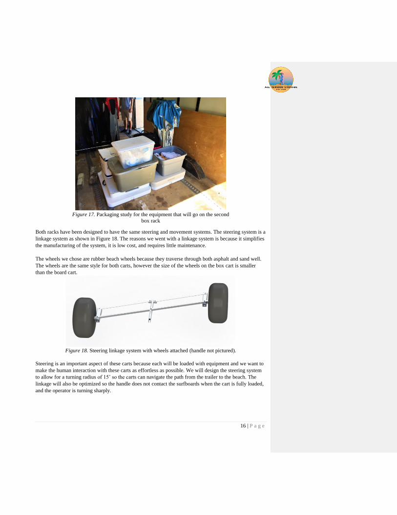
Figure 15. The second iteration of the square vertical frame design
Our second final concept design is the box structure shown in Figure 16. This structure’s purpose is to
hold all the equipment pictured in Figure 17. The heaviest equipment that will be stored on this structure
are the four tables AmpSurf owns. These tables will be stored on the lower level of the structure in order
to lower the center of gravity as much as possible. The overall dimensions of the structure are 53” x 71” x
44”. These dimensions were determined from the size of the tables as shown in Figure 17. In order to
secure all this equipment, we have also incorporated anchors to hook a cargo net around so none of the
equipment falls off during transportation.
Figure 16. CAD rendering of our final design for the box structure
16 | P a g e
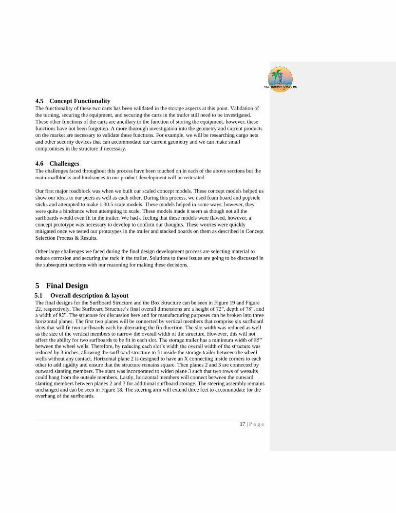
Figure 17. Packaging study for the equipment that will go on the second
box rack
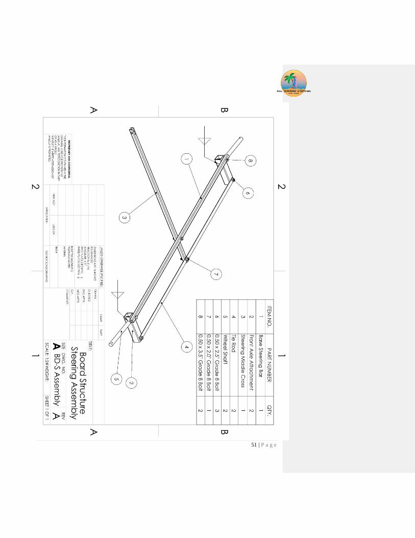
Both racks have been designed to have the same steering and movement systems. The steering system is a
linkage system as shown in Figure 18. The reasons we went with a linkage system is because it simplifies
the manufacturing of the system, it is low cost, and requires little maintenance.
The wheels we chose are rubber beach wheels because they traverse through both asphalt and sand well.
The wheels are the same style for both carts, however the size of the wheels on the box cart is smaller
than the board cart.
Figure 18. Steering linkage system with wheels attached (handle not pictured).
Steering is an important aspect of these carts because each will be loaded with equipment and we want to
make the human interaction with these carts as effortless as possible. We will design the steering system
to allow for a turning radius of 15’ so the carts can navigate the path from the trailer to the beach. The
linkage will also be optimized so the handle does not contact the surfboards when the cart is fully loaded,
and the operator is turning sharply.
17 | P a g e
4.5 Concept Functionality The functionality of these two carts has been validated in the storage aspects at this point. Validation of
the turning, securing the equipment, and securing the carts in the trailer still need to be investigated.
These other functions of the carts are ancillary to the function of storing the equipment, however, these
functions have not been forgotten. A more thorough investigation into the geometry and current products
on the market are necessary to validate these functions. For example, we will be researching cargo nets
and other security devices that can accommodate our current geometry and we can make small
compromises in the structure if necessary.
4.6 Challenges The challenges faced throughout this process have been touched on in each of the above sections but the
main roadblocks and hindrances to our product development will be reiterated.
Our first major roadblock was when we built our scaled concept models. These concept models helped us
show our ideas to our peers as well as each other. During this process, we used foam board and popsicle
sticks and attempted to make 1:30.5 scale models. These models helped in some ways, however, they
were quite a hindrance when attempting to scale. These models made it seem as though not all the
surfboards would even fit in the trailer. We had a feeling that these models were flawed, however, a
concept prototype was necessary to develop to confirm our thoughts. These worries were quickly
mitigated once we tested our prototypes in the trailer and stacked boards on them as described in Concept
Selection Process & Results.
Other large challenges we faced during the final design development process are selecting material to
reduce corrosion and securing the rack in the trailer. Solutions to these issues are going to be discussed in
the subsequent sections with our reasoning for making these decisions.
5 Final Design
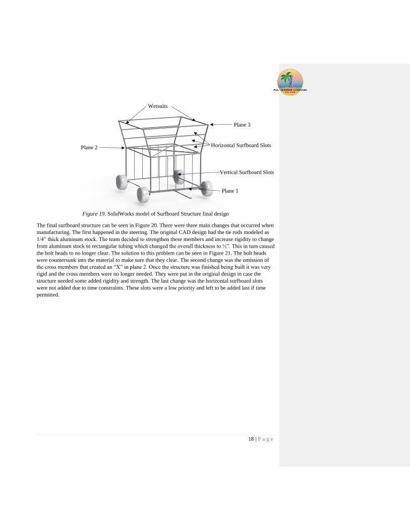
5.1 Overall description & layout The final designs for the Surfboard Structure and the Box Structure can be seen in Figure 19 and Figure
22, respectively. The Surfboard Structure’s final overall dimensions are a height of 72”, depth of 78”, and
a width of 82”. The structure for discussion here and for manufacturing purposes can be broken into three
horizontal planes. The first two planes will be connected by vertical members that comprise six surfboard
slots that will fit two surfboards each by alternating the fin direction. The slot width was reduced as well
as the size of the vertical members to narrow the overall width of the structure. However, this will not
affect the ability for two surfboards to be fit in each slot. The storage trailer has a minimum width of 85”
between the wheel wells. Therefore, by reducing each slot’s width the overall width of the structure was
reduced by 3 inches, allowing the surfboard structure to fit inside the storage trailer between the wheel
wells without any contact. Horizontal plane 2 is designed to have an X connecting inside corners to each
other to add rigidity and ensure that the structure remains square. Then planes 2 and 3 are connected by
outward slanting members. The slant was incorporated to widen plane 3 such that two rows of wetsuits
could hang from the outside members. Lastly, horizontal members will connect between the outward
slanting members between planes 2 and 3 for additional surfboard storage. The steering assembly remains
unchanged and can be seen in Figure 18. The steering arm will extend three feet to accommodate for the
overhang of the surfboards.
18 | P a g e
Figure 19. SolidWorks model of Surfboard Structure final design
The final surfboard structure can be seen in Figure 20. There were three main changes that occurred when
manufacturing. The first happened in the steering. The original CAD design had the tie rods modeled as
1/4” thick aluminum stock. The team decided to strengthen these members and increase rigidity to change
from aluminum stock to rectangular tubing which changed the overall thickness to ½”. This in turn caused
the bolt heads to no longer clear. The solution to this problem can be seen in Figure 21. The bolt heads
were countersunk into the material to make sure that they clear. The second change was the omission of
the cross members that created an “X” in plane 2. Once the structure was finished being built it was very
rigid and the cross members were no longer needed. They were put in the original design in case the
structure needed some added rigidity and strength. The last change was the horizontal surfboard slots
were not added due to time constraints. These slots were a low priority and left to be added last if time
permitted.
Plane 1
Plane 3
Plane 2
Vertical Surfboard Slots
Wetsuits
Horizontal Surfboard Slots

19 | P a g e
Figure 20. Finished Surfboard Structure.

20 | P a g e
Figure 21. Steering Bolt Head Clearance Solution.
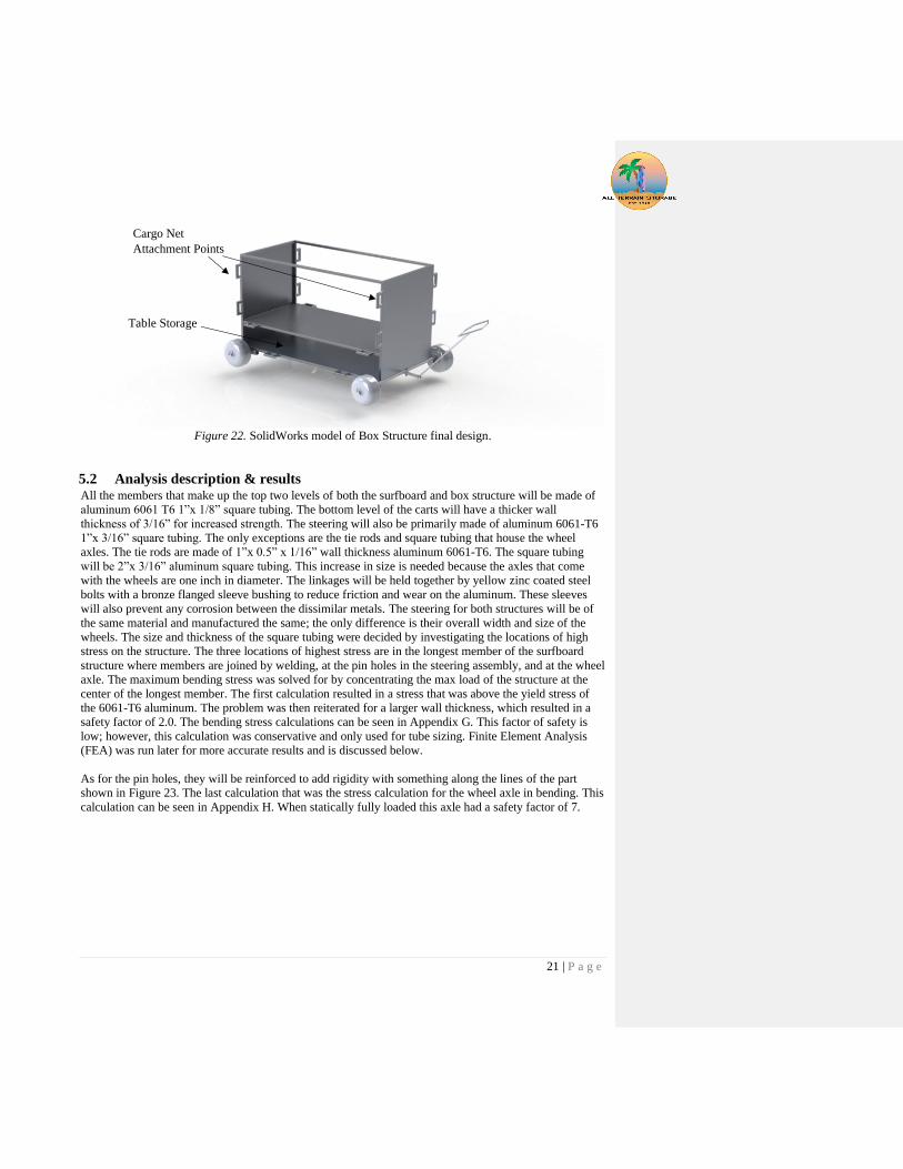
The box structure was not manufactured due to lack of funding and manufacturing time. The design and
analysis of box structure will remain included for future development. The box structure shown in Figure
22 has two storage areas. The lower open area is the storage for AmpSurf’s tables. The second level will
store the boxes, stand up tarps, first aid kit, and other miscellaneous event equipment. The floors will be
comprised of aluminum grating (not pictured) to ensure that the sand stays on the beach, and the
equipment can dry if necessary. Cargo nets will be attached to the points shown. This will allow for easy
loading and increased carrying capacity. The tables will be secured by cargo nets, or bungee cords using
similar attachment points. The steering can be seen in Figure 18.
21 | P a g e
Figure 22. SolidWorks model of Box Structure final design.
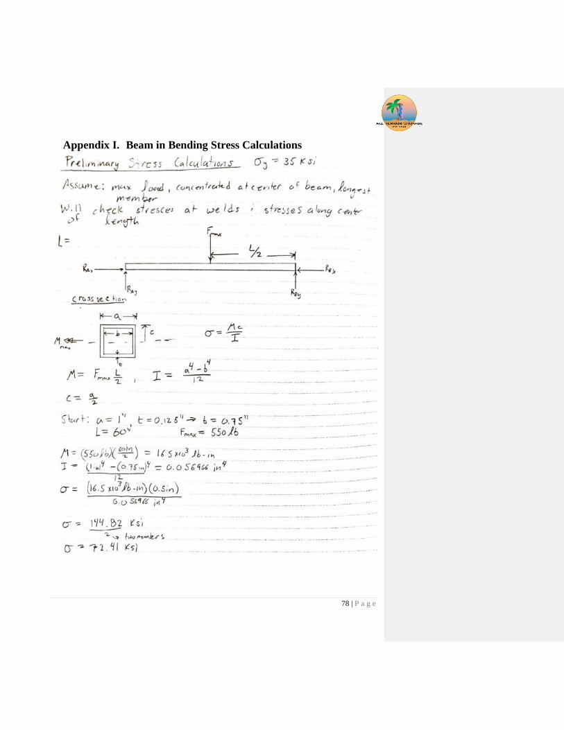
5.2 Analysis description & results All the members that make up the top two levels of both the surfboard and box structure will be made of
aluminum 6061 T6 1”x 1/8” square tubing. The bottom level of the carts will have a thicker wall
thickness of 3/16” for increased strength. The steering will also be primarily made of aluminum 6061-T6
1”x 3/16” square tubing. The only exceptions are the tie rods and square tubing that house the wheel
axles. The tie rods are made of 1”x 0.5” x 1/16” wall thickness aluminum 6061-T6. The square tubing
will be 2”x 3/16” aluminum square tubing. This increase in size is needed because the axles that come
with the wheels are one inch in diameter. The linkages will be held together by yellow zinc coated steel
bolts with a bronze flanged sleeve bushing to reduce friction and wear on the aluminum. These sleeves
will also prevent any corrosion between the dissimilar metals. The steering for both structures will be of
the same material and manufactured the same; the only difference is their overall width and size of the
wheels. The size and thickness of the square tubing were decided by investigating the locations of high
stress on the structure. The three locations of highest stress are in the longest member of the surfboard
structure where members are joined by welding, at the pin holes in the steering assembly, and at the wheel
axle. The maximum bending stress was solved for by concentrating the max load of the structure at the
center of the longest member. The first calculation resulted in a stress that was above the yield stress of
the 6061-T6 aluminum. The problem was then reiterated for a larger wall thickness, which resulted in a
safety factor of 2.0. The bending stress calculations can be seen in Appendix G. This factor of safety is
low; however, this calculation was conservative and only used for tube sizing. Finite Element Analysis
(FEA) was run later for more accurate results and is discussed below.
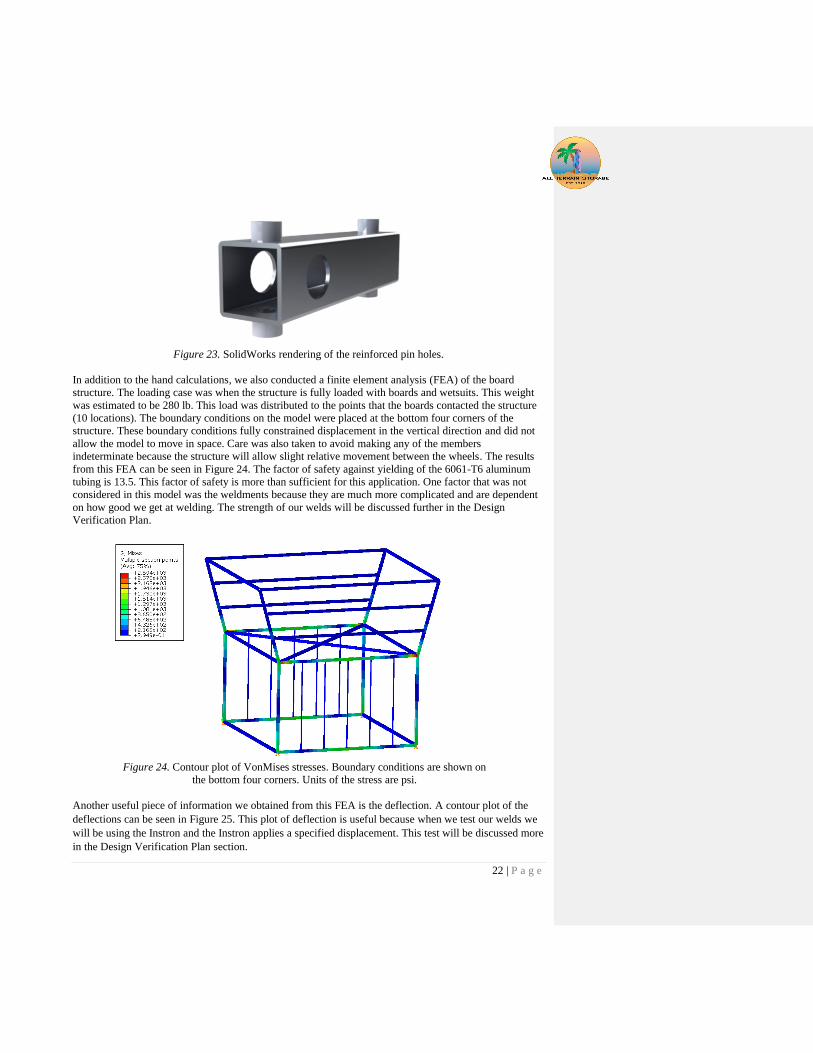
As for the pin holes, they will be reinforced to add rigidity with something along the lines of the part
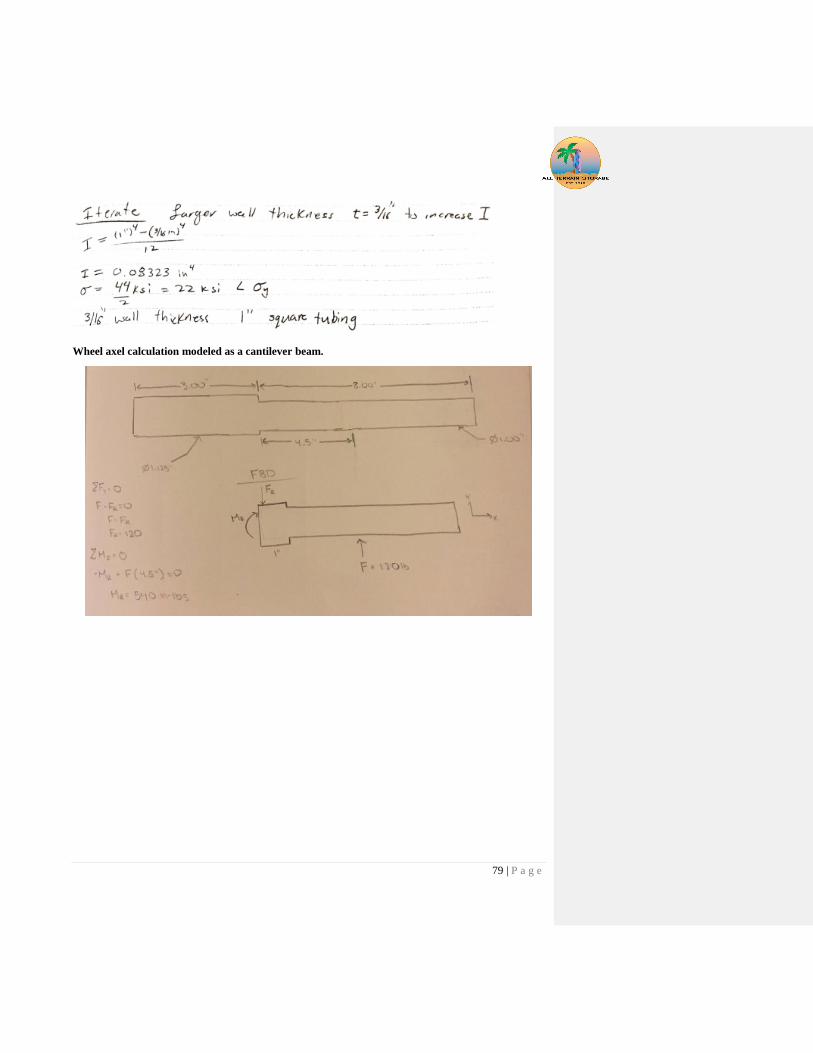
shown in Figure 23. The last calculation that was the stress calculation for the wheel axle in bending. This
calculation can be seen in Appendix H. When statically fully loaded this axle had a safety factor of 7.
Table Storage
Cargo Net
Attachment Points
22 | P a g e
Figure 23. SolidWorks rendering of the reinforced pin holes.
In addition to the hand calculations, we also conducted a finite element analysis (FEA) of the board
structure. The loading case was when the structure is fully loaded with boards and wetsuits. This weight
was estimated to be 280 lb. This load was distributed to the points that the boards contacted the structure
(10 locations). The boundary conditions on the model were placed at the bottom four corners of the
structure. These boundary conditions fully constrained displacement in the vertical direction and did not
allow the model to move in space. Care was also taken to avoid making any of the members
indeterminate because the structure will allow slight relative movement between the wheels. The results
from this FEA can be seen in Figure 24. The factor of safety against yielding of the 6061-T6 aluminum
tubing is 13.5. This factor of safety is more than sufficient for this application. One factor that was not
considered in this model was the weldments because they are much more complicated and are dependent
on how good we get at welding. The strength of our welds will be discussed further in the Design
Verification Plan.
Figure 24. Contour plot of VonMises stresses. Boundary conditions are shown on
the bottom four corners. Units of the stress are psi.
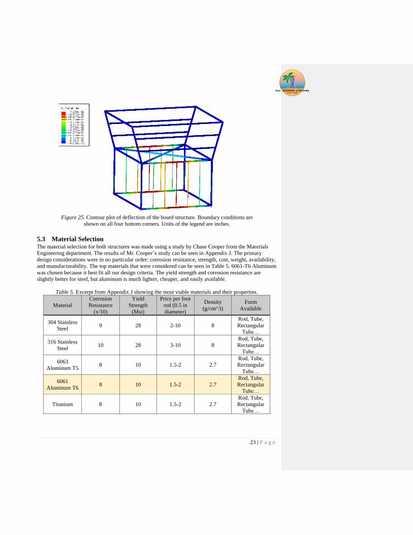
Another useful piece of information we obtained from this FEA is the deflection. A contour plot of the
deflections can be seen in Figure 25. This plot of deflection is useful because when we test our welds we
will be using the Instron and the Instron applies a specified displacement. This test will be discussed more
in the Design Verification Plan section.
23 | P a g e
Figure 25. Contour plot of deflection of the board structure. Boundary conditions are
shown on all four bottom corners. Units of the legend are inches.
5.3 Material Selection The material selection for both structures was made using a study by Chase Cooper from the Materials
Engineering department. The results of Mr. Cooper’s study can be seen in Appendix J. The primary
design considerations were in no particular order: corrosion resistance, strength, cost, weight, availability,
and manufacturability. The top materials that were considered can be seen in Table 5. 6061-T6 Aluminum
was chosen because it best fit all our design criteria. The yield strength and corrosion resistance are
slightly better for steel, but aluminum is much lighter, cheaper, and easily available.
Table 5. Excerpt from Appendix J showing the most viable materials and their properties.
Material
Corrosion
Resistance
(x/10)
Yield
Strength
(Msi)
Price per foot
rod (0.5 in
diameter)
Density
(g/cm^3)
Form
Available
304 Stainless
Steel 9 28 2-10 8
Rod, Tube,
Rectangular
Tube…
316 Stainless
Steel 10 28 3-10 8
Rod, Tube,
Rectangular
Tube…
6063
Aluminum T5 8 10 1.5-2 2.7
Rod, Tube,
Rectangular
Tube…
6061
Aluminum T6 8 10 1.5-2 2.7
Rod, Tube,
Rectangular
Tube…
Titanium 8 10 1.5-2 2.7
Rod, Tube,
Rectangular
Tube…
24 | P a g e
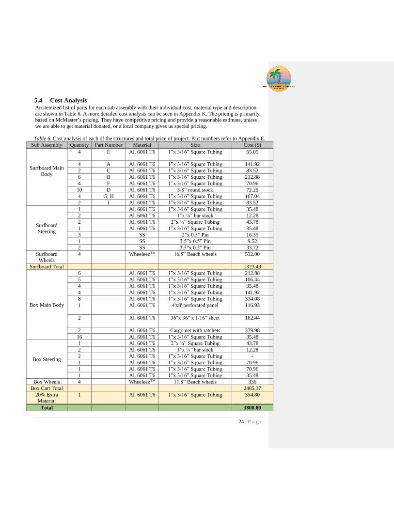
5.4 Cost Analysis An itemized list of parts for each sub assembly with their individual cost, material type and description
are shown in Table 6. A more detailed cost analysis can be seen in Appendix K. The pricing is primarily
based on McMaster’s pricing. They have competitive pricing and provide a reasonable estimate, unless
we are able to get material donated, or a local company gives us special pricing.
Table 6. Cost analysis of each of the structures and total price of project. Part numbers refer to Appendix E.
Sub Assembly Quantity Part Number Material Size Cost ($)
Surfboard Main
Body
4 E Al. 6061 T6 1”x 3/16” Square Tubing 65.05
4 A Al. 6061 T6 1”x 3/16” Square Tubing 141.92
2 C Al. 6061 T6 1”x 3/16” Square Tubing 83.52
6 B Al. 6061 T6 1”x 3/16” Square Tubing 212.88
4 F Al. 6061 T6 1”x 3/16” Square Tubing 70.96
10 D Al. 6061 T6 3/8” round stock 72.25
4 G, H Al. 6061 T6 1”x 3/16” Square Tubing 167.04
2 I Al. 6061 T6 1”x 3/16” Square Tubing 83.52
Surfboard
Steering
1 Al. 6061 T6 1”x 3/16” Square Tubing 35.48
2 Al. 6061 T6 1”x ¼” bar stock 12.28
2 Al. 6061 T6 2”x ¼” Square Tubing 43.78
1 Al. 6061 T6 1”x 3/16” Square Tubing 35.48
3 SS 2”x 0.5” Pin 16.35
1 SS 3.5”x 0.5” Pin 9.52
2 SS 3.5”x 0.5” Pin 33.72
Surfboard
Wheels
4 WheeleezTM 16.5” Beach wheels 532.00
Surfboard Total 1323.43
Box Main Body
6 Al. 6061 T6 1”x 3/16” Square Tubing 212.88
5 Al. 6061 T6 1”x 3/16” Square Tubing 106.44
4 Al. 6061 T6 1”x 3/16” Square Tubing 35.48
4 Al. 6061 T6 1”x 3/16” Square Tubing 141.92
8 Al. 6061 T6 1”x 3/16” Square Tubing 334.08
1 Al. 6061 T6 4'x8' perforated panel
116.93
2 Al. 6061 T6 36"x 36" x 1/16” sheet
162.44
2 Al. 6061 T6 Cargo net with ratchets 379.98
16 Al. 6061 T6 1”x 3/16” Square Tubing 35.48
Box Steering
1 Al. 6061 T6 2”x ¼” Square Tubing 43.78
2 Al. 6061 T6 1”x ¼” bar stock 12.28
2 Al. 6061 T6 1”x 3/16” Square Tubing -
1 Al. 6061 T6 1”x 3/16” Square Tubing 70.96
1 Al. 6061 T6 1”x 3/16” Square Tubing 70.96
1 Al. 6061 T6 1”x 3/16” Square Tubing 35.48
Box Wheels 4 WheeleezTM 11.8” Beach wheels 336
Box Cart Total 2485.37
20% Extra
Material
1 Al. 6061 T6 1”x 3/16” Square Tubing 354.80
Total 3808.80

25 | P a g e
5.5 Safety, maintenance, & repair considerations (updated FMEA) Safety is of utmost importance when creating a product with which humans will be interacting. The safety
concerns we addressed throughout the design process were sharp edges, protruding tubes, moving
equipment, and tipping. These issues were accounted for throughout the design process, but some still
need follow-up through the manufacturing phase.
The issues that need to be addressed while manufacturing are the sharp edges and moving equipment.
Eliminating sharp edges is a simple and important safety consideration because there will be many
volunteers interacting with this structure and it cannot cut them. This issue can be mitigated by grinding
down welds that are sharp and covering all sharp edged square tubes with foam. Equipment shifting while
on the structure is another large safety issue because if surfboards are unsecured and fall off the structure
at any time the cart is being used, then a volunteer may be injured. This risk will be mitigated through
safety netting on both sides of the carts and possibly the top of the box cart as well. This needs to be
addressed during the manufacturing phase because there needs to be structurally sound connection points
for the nets, otherwise these nets will be useless.
One issue that needs to be addressed when using the structures is tipping. This was addressed in our
design and will not be an issue if the carts are loaded correctly; however, there is a possibility of loading
the structure so the center of gravity is too high. If the center of gravity is too high then the possibility of
tipping becomes much greater when operating the cart. Safety is extremely important for us and
AmpSurf, so for this reason we will be continually evaluating the safety until we deliver the final product.
We would like these carts to need as little maintenance as possible, however maintenance and repairs are
inevitable. The main maintenance areas will be putting air in the beach wheels and periodic inspection of
the structure. One other unlikely failure would be rust on the structure. Keeping air in the wheels is a
simple and necessary maintenance task for an AmpSurf employee or volunteer to check before operating
the carts. Periodic inspection of the structure is an important maintenance issue because if cracks develop
in an area of the structure due to fatigue or unexpected loading then cracks or yielding may occur. If signs
of failure are detected early, then major failures may be prevented before members fully break, or yield to
a point where the structure fails more catastrophically. If the structure does begin to corrode or rust, then
some type of coating would have to be applied to prevent further corrosion. In the case of a minor failure,
a repair may be able to save the structure.
The repairs that one may need to make are welding, disassembly, replacing parts, cleaning, and coating
the structure. Welding would be a repair to a crack that is detected, most likely at one of the current
welds. Disassembling and replacing parts would be concentrated in the steering system, as that is the only
system that is assembled. Cleaning and coating will also go hand in hand because if rust does appear then
the rust should be cleaned off well before a protective coating is applied. The necessary equipment for
repairing this structure is a set of end wrenches, or sockets, a TIG welder, 4043 filler, wire brushes, and
the applicator for the protective coating.
6 Manufacturing
6.1 Detailed Manufacturing Description As stated in other sections the box structure was not manufactured due to budget and time constraints.
The manufacturing procedure for this box structure will remain the same as the surfboard cart.
26 | P a g e
The manufacturing of the surfboard cart begins with ordering tubing material, hardware, and the beach
wheels. In order to save money on shipping, all our square tubing and hardware came from McMaster-
Carr. By having it all come from one vendor we saved the shipping cost and shipping time
The surfboard structure was fully TIG welded. Due to the structures being made of 6061-T6 square
aluminum tubing, we uses 4043 filler rod, as that is the filler rod necessary to weld 6061-T6 aluminum.
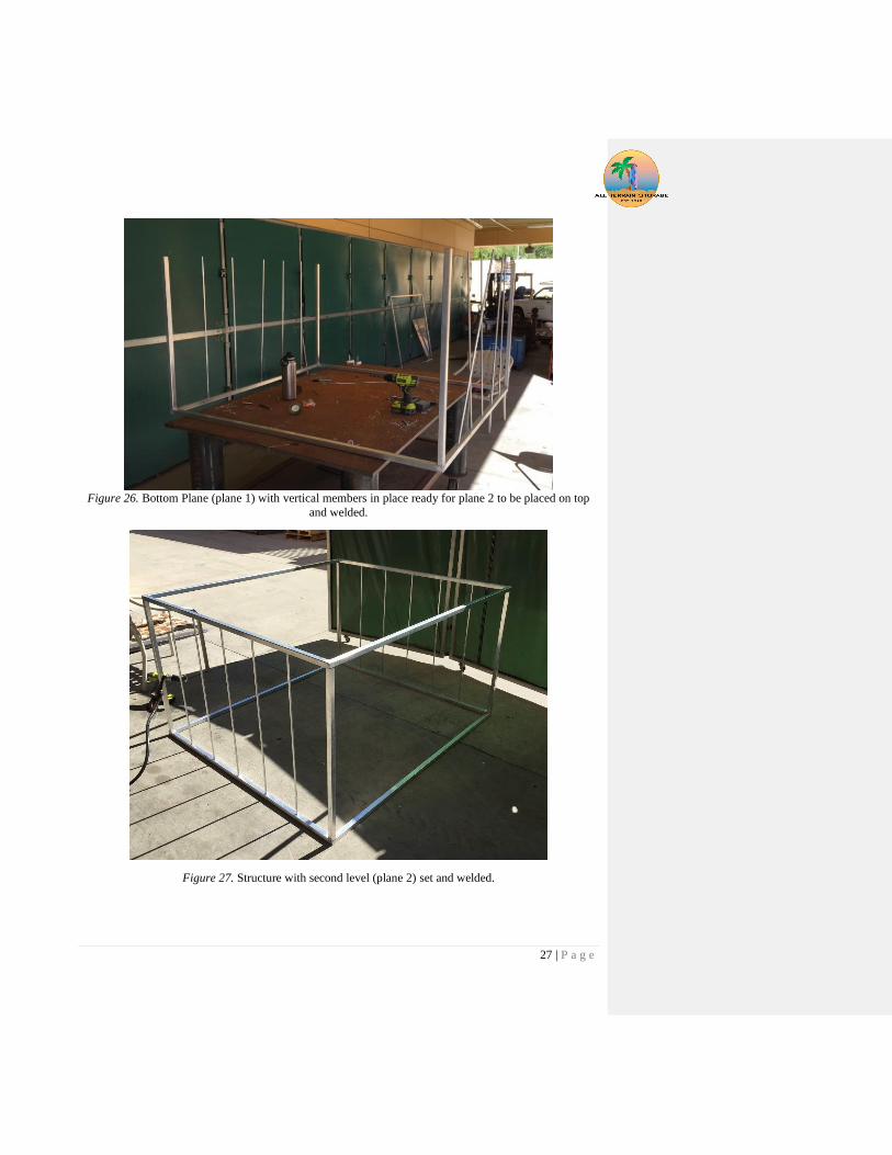
First the members that make up the horizontal planes were cut and prepped for welding. The bottom plane
was then welded together. While one team member was welding the other team members cut the rest of
the parts of the structure as well as assisted with positioning for welding. The milestones of
manufacturing can be seen in Figure 26, Figure 27, and Figure 28.
Once each tube end is notched to its final shape, we placed all the tubes together and tack welded each of
the members together. Tack welding first gives the structure more rigidity to prevent it from warping
when welding. When all members are tacked, we can begin to fully weld one inch at a time and to move
around the different corners of the structure to allow areas to cool, until the entire floor is complete. This
entire process was repeated for each of the different horizontal levels for each structure. Once all the
horizontal levels are completed the vertical members were tacked on to begin brining levels together
starting from the bottom floor. A 90 degree tee was used to ensure that the vertical members are at 90
degrees. After setting the tubes to 90 degrees we tack welded two sides on the members, then checked for
90 degrees once again. If the members were not at 90 degrees more tacks were added in a location to
warp the member to get it to 90 degrees. This process was repeated for all vertical members on the
surfboard structures. The last members necessary to weld on the surfboard cart were the angled members
that bring together the second and third horizontal planes. With those members welded on, the structure
was now almost fully completed and we would begin to manufacture the steering system.
We began manufacturing the steering system by cutting the steering linkages to their final length using a
tape measure and an aluminum cut off saw. Once all members were cut to their final length we located all
holes in each member. We used a tape measure to locate the center point of each hole and then once
located we used a drill press to drill the holes. The steering spindle was pressed into the wheel bar hole
and then welded all around where the spindle slides into the hole. In order to prevent the holes in each bar
from wear we added bushings to distribute the load of the bolts. There are a total of 12 bushings on the
steering members. With all holes drilled out and bushings on, we began to assemble the steering system
onto the structures using the hardware we obtained from McMaster that consisted of screws and nuts.
Lastly, we put on the beach wheels obtained from our sponsor on each spindle and secured them onto the
spindle using a cotter pin. The only things left are all the cargo nets and straps, which will be added to
hold all equipment during transportation. After adding the cargo nets and cords the manufacturing of the
cart was complete.
27 | P a g e
Figure 26. Bottom Plane (plane 1) with vertical members in place ready for plane 2 to be placed on top
and welded.
Figure 27. Structure with second level (plane 2) set and welded.

28 | P a g e
Figure 28. The third level (plane 3) being welded.
6.2 Manufacturing Challenges The most difficult part of the manufacturing process for the surfboard cart was the welding of the
structure. TIG welding aluminum was a difficult process and takes a lot of practice to get proper welding
penetration. Without proper penetration, our structure risks not being structurally stable, which means that
when fully loaded, we could experience failures in that system. It is therefore important for us to obtain
proper penetration with all our welds. Along with proper penetration, aluminum is also prone to warping
during welding. We did not experience any warping in our structure due to welding different areas of the
structure allowing previous spots to cool down before continuing welding. Perhaps the most difficult
thing about welding aluminum though was keeping the weld clean. Having the right amount of argon
flow, a clean electrode, and clean material are all vital components to having a good weld. If the weld is
dirty you notice that the filler does not want to join in with the base material and you will not get a proper
weld.
7 Design Verification Plan
Testing is a critical factor whenever a part is designed and manufactured; this is especially true in the case
of our structures. There are two pieces of our design we need to test to ensure our cart will not fail. The
first failure we are investigating is a failed weld. The reason we are concerned with this failure is because
we are going to be welding the whole structure ourselves. We are not certified welders and aluminum TIG
is difficult to weld as mentioned in the manufacturing plan. The second test we will be running is a test of
the strength of the drilled holes on the steering subsystem. These holes have bolts running through them
29 | P a g e
and allow for rotation of the steering components. The reason for this test is because we are concerned
that the holes will yield as the steering system is subjected to bending loads from the steering handle.
The tests we are going to run for the welds are visual inspection for proper weld penetration. The visual
inspection test is the most important test we will be conducting because this test will happen before,
during, and after every weld. This test simply requires us to look at the welds to ensure there are no
glaring flaws in the beads or surrounding material. Before the weld is made, we will ensure that the
material is as clean as possible to help minimize the effect of oxidation and other impurities that can
decrease the strength of the weld. After the weld is complete, a thorough visual inspection will be
conducted. The typical flaws that we will be looking for are undercut, lack of penetration, cracks,
porosity, and inclusions.
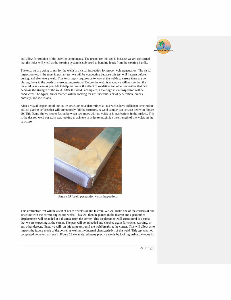
After a visual inspection of our entire structure have determined all our welds have sufficient penetration
and no glaring defects that will prematurely fail the structure. A weld sample can be seen below in Figure
29. This figure shows proper fusion between two tubes with no voids or imperfections in the surface. This
is the desired weld our team was looking to achieve in order to maximize the strength of the welds on the
structure.
Figure 29. Weld penetration visual inspection.
This destructive test will be a test of our 90° welds on the Instron. We will make one of the corners of our
structure with the correct angles and welds. This will then be placed in the Instron and a prescribed
displacement will be added at a distance from the corner. This displacement will correspond to a stress
that we are expecting at the corner. The part will be unloaded and checked again for cracks, warping, or
any other defects. Next, we will run this same test until the weld breaks at the corner. This will allow us to
inspect the failure mode of the corner as well as the internal characteristics of the weld. This test was not
completed however, as seen in Figure 29 we analyzed many practice welds by looking inside the tubes for

30 | P a g e
sufficient penetration and ground down welds to check for complete fusion of the previously separate
pieces. These tests were completed with success before we began welding on the actual structure.
The next test we would like to run is a test of the integrity of the drilled holes in the square tubing. This
test will allow us to see if the holes need to be reinforced or if the wall thickness alone can prevent
localized yielding of the aluminum tube. The location of concern on the steering subsystem is shown in
Figure 30. This is a concern because it will see large bending loads from lifting or pushing down on the
handle.
Figure 30. Steering subsystem and the main point of concern for localized
yielding of the drilled hole.
This was our initial plan for testing this location however, we did not complete this test because we made
a design change. Initially we were planning on testing three different configurations of tube-bolt
connections. The first one was simply a bolt running through the hole in the tube. The second would have
been a welded insert into the hole that the bolt will pass through and the third option was an aluminum
block inside the tube that the bolt runs through. These three tests were going to be conducted on the
Instron at the same time as our weld tests.
The setup for this test will be to assemble the bolted joint connection in single shear as it is designed and
apply a load to one of the members until the hole yields locally, at which point the design has failed. This
will be repeated with the two reinforced concepts to determine which method requires the largest force to
break a component of the design. Since this test is comparative, the setup in the Instron does not have to
be an exact representation of the assembly that will be on the cart. However, if our results are not
statistically significant we may investigate a more representative fixturing setup. We did not need to run
this test because of an increase in the wall thickness and large bolt diameter almost completely occupied
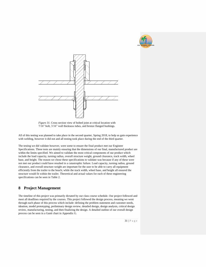
the space inside the tube as seen in Figure 31 and discussed below.
To connect the steering to the structure we used two bronze flanged bushings, a 7/16” grade 8 bolt, and
locknut. A cross sectional view of these joints can be visualized in Figure 31. The two bronze bushings
are embedded with oil to help allow the joint to rotate while still allowing for the bolt to be fully torqued
down. To further decrease friction in this joint we could have added a lubricated washer in between the
two aluminum tubes that are currently in contact with each other.
31 | P a g e
Figure 31. Cross section view of bolted joint at critical location with
7/16” bolt, 3/16” wall thickness tubes, and bronze flanged bushings.
All of this testing was planned to take place in the second quarter, Spring 2018, to help us gain experience
with welding, however it did not and all testing took place during the end of the third quarter.
The testing we did validate however, were some to ensure the final product met our Engineer
Specifications. These tests are mainly ensuring that the dimensions of our final, manufactured product are
within the limits specified. We aimed to validate the most critical components of our product which
include the load capacity, turning radius, overall structure weight, ground clearance, track width, wheel
base, and height. The reason we chose these specifications to validate was because if any of these were
not met our product could have resulted in a catastrophic failure. Load capacity, turning radius, ground
clearance, and overall structure weight are important for the user to be able to carry all equipment
efficiently from the trailer to the beach; while the track width, wheel base, and height all ensured the
structure would fit within the trailer. Theoretical and actual values for each of these engineering
specifications can be seen in Table 2.
8 Project Management
The timeline of this project was primarily dictated by our class course schedule. Our project followed and
meet all deadlines required by the courses. This project followed the design process, meaning we went
through each phase of this process which include: defining the problem statement and customer needs,
ideation, model prototyping, preliminary design review, detailed design, design analysis, critical design
review, manufacturing, testing, and then finalizing the design. A detailed outline of our overall design
process can be seen in a Gantt chart in Appendix G.

32 | P a g e
However, if we were able to go back we would have slightly gone off the course schedule in order to
allow ourselves to have more manufacturing time. Our project was manufacturing heavy so giving
ourselves more time would have been greatly beneficial. Also one aspect of project management that we
failed to give a lot of attention to was project funding. If we had started to find funding earlier in the
project we could have ordered our material sooner and created some more prototypes and iterations
before going with our final design.
Overall though we still believe we managed ourselves well as we completed the entire project before the
due date. Every one of our members knew the tasks they needed to accomplish by when and we all
completed them.
9 Conclusion & Recommendations
The goal of All Terrain Storage is to design two portable storage devices and manufacture the surfboard
cart for the non-profit organization AmpSurf. The box cart is to hold administration boxes, pop up tarps,
tables, and chairs. The surfboard cart is to store and transport 16 large surfboards and upwards of 25
wetsuits. The storage devices met many of the requirements stated in Table 2. Engineering Specification
Sheet, and we are confident that it would meet the ones we did not validate.
Our project will allow AmpSurf to transport their equipment from their trailer to the beach at different
events they host throughout the year. The surfboard cart has been tested and is able to hold the 16
surfboards currently owned by AmpSurf and even has to potential to accommodate more if AmpSurf
purchases more. Overall the surfboard cart has been tested and has met all our critical design
specifications, such as having a load capacity of at least 400 lbs, having a turning radius less than 15 feet,
weighing under 150 lbs, etc. Currently the only thing to still be tested is the steering effort required when
the cart is fully loaded with all equipment. This could prove to be an issue because after manufacturing
we noticed that the tires deflected much more than we had previously anticipated. With such a large
contact patch the user could experience more resistance when turning the structure. In order to decrease
the contact patch we recommend users to pump up the tires to their max rating of 4 psig. Another issue
that may arise with a fully loaded cart is the large deflections in the steering system as more user input is
required. This problem could be improved by welding additional blocks on the sides of the members that
the steering system is mounted to in order to create a contact area between surfaces instead of the bolt
taking the entire moment by itself.
Aside from these potential issues, some additional steps AmpSurf could take in order to improve the
structure are adding the horizontal members to the upper level of the surfboard cart. This will create
specified area for surfboards to go, as opposed to stacking them on the upper level. In addition adding
steer stops to the structure could prevent the wheels from interfering with the structure when turning.
Having the wheels rub against the structure could potentially cause accelerated wear on them which is
undesirable. Until those stops are added the operator should be aware of the wheels position when
steering.
Overall we believe that this project was successful as we completed the ideation, design, and
manufacturing of the surfboard cart that will be delivered to AmpSurf. This cart will greatly benefit
AmpSurf and we are proud to turn it over to them and watch as it allows them to continue helping
numerous people with disabilities.
33 | P a g e
10 References
Cardoso, Francisco Sena and Kim J.R. Rasmussen. "Finite element (FE) modelling of storage rack
frames." Elsevier Ltd. (2016): 2-13.
Casafont, Miquel, et al. "Design of steel storage rack columns via the direct strength method." American
Society of Civil Engineers (2013): 669-678.
Dai, Lisusi, Xianzhong Zhao and Kin J.R. Rasmussen. "Flexural behaviour of steel storage rack beam-to-
upright bolted connections." Elsevier (2006): 203-217.
Hatfull, Mark. Quiver Kaddy. n.d. Online. 17 Dec. 2018.
Helterbrand, Arlen. PORTABLE CONVERTIBLE WHEELCHAIR. United States: Patent 8,678,402. 25
March 2014.
Mac Sports Heavy Duty Collapsible Folding All Terrain Utility Beach Wagon Cart. n.d. Online. 17 Jan.
2018.
Qinglei, Jiang, et al. "Characterization on strength and toughness of welded joint for Q550 steel." Indian
Academy of Sciences (2011): 162-167.
Skoff, Shawn. SURFBOARD RACK FOR VEHICLES. United States: Patent Pub. No.:0261136 A1. 18
April 2008.
Wang, Youde, et al. "Predicting the residual strength and deformability of corroded steel plate based on
the corrosion morphology." Elsevier Ltd. (2017): 778-791.
Wheeleez Beach Cart. n.d. Online. 17 Jan. 2018.
34 | P a g e
Appendix A. Customer Wants/Needs
35 | P a g e
Appendix B. QFD House of Quality

36 | P a g e
Appendix C. Decision Matrices

37 | P a g e
38 | P a g e
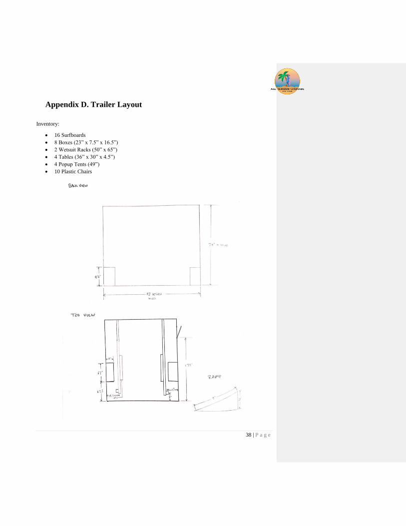
Appendix D. Trailer Layout
Inventory:
• 16 Surfboards
• 8 Boxes (23” x 7.5” x 16.5”)
• 2 Wetsuit Racks (50” x 65”)
• 4 Tables (36” x 30” x 4.5”)
• 4 Popup Tents (49”)
• 10 Plastic Chairs

39 | P a g e
40 | P a g e
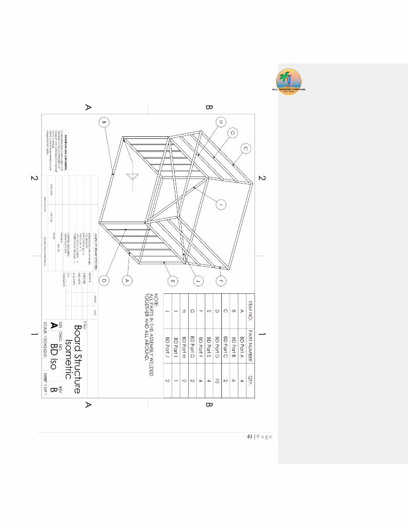
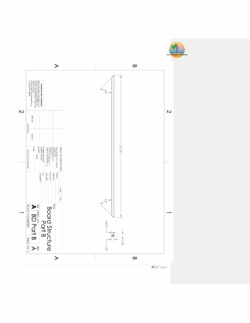
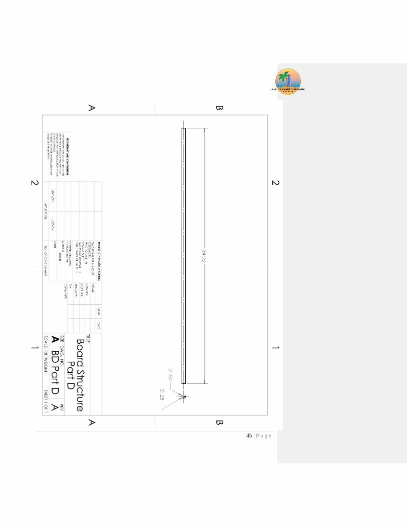
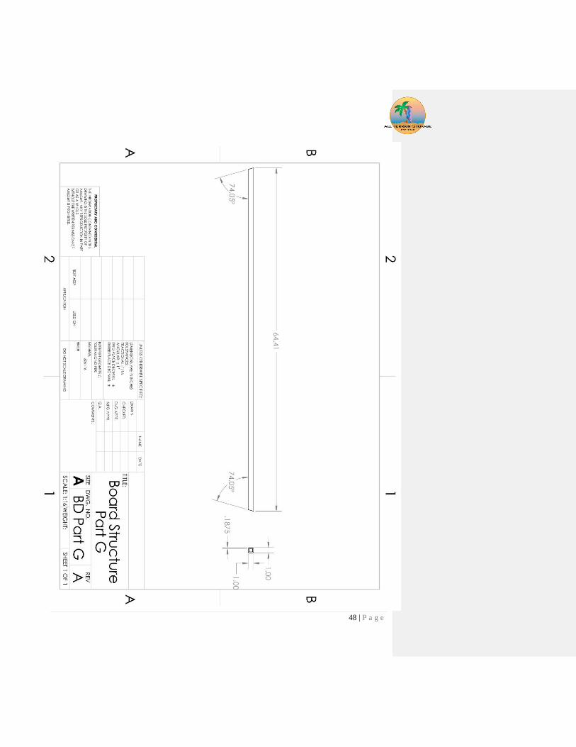
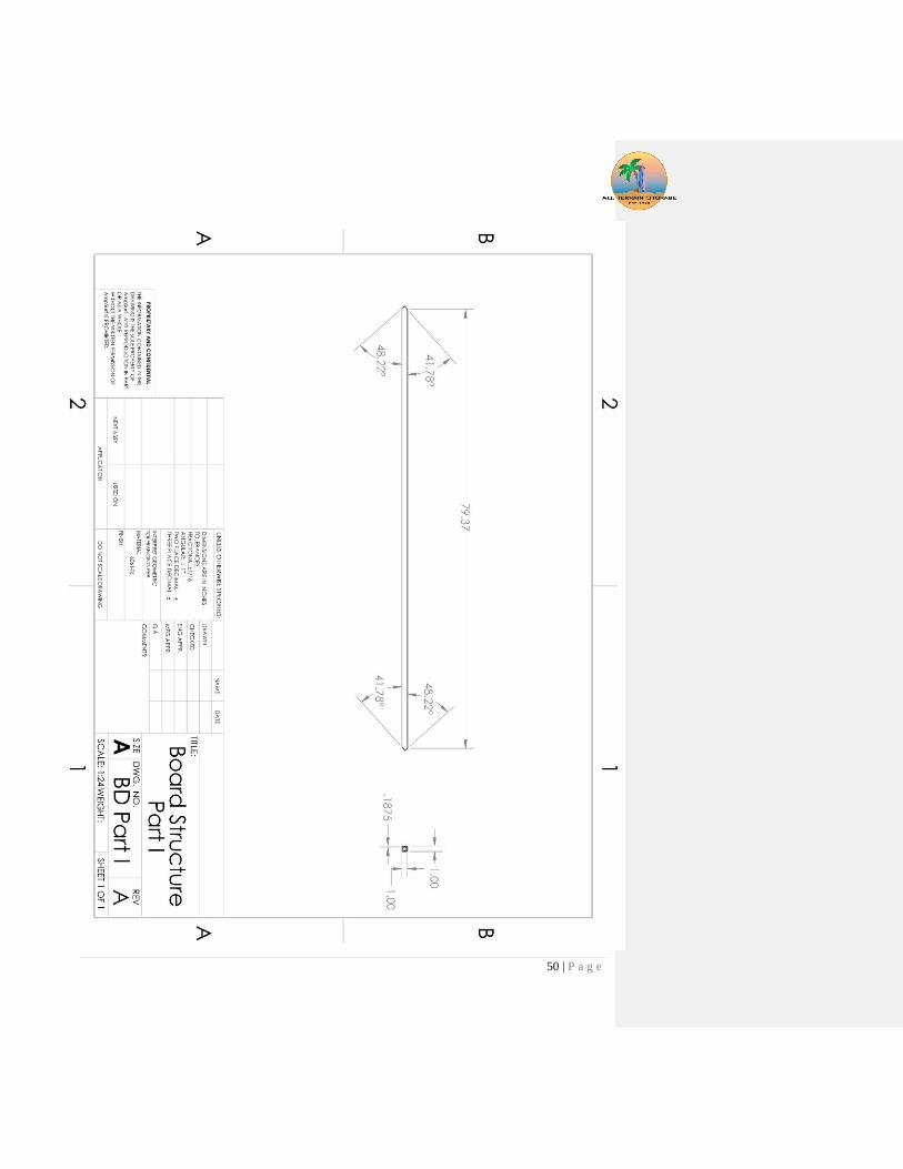
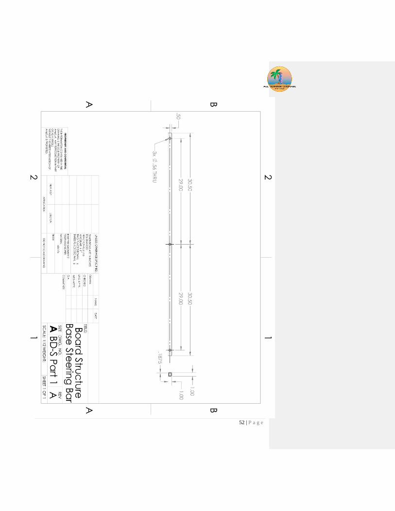
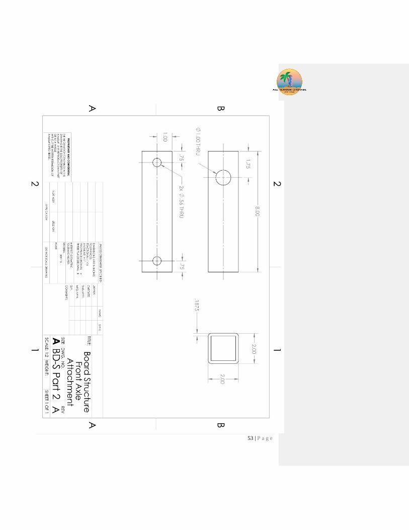
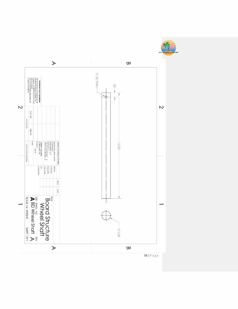
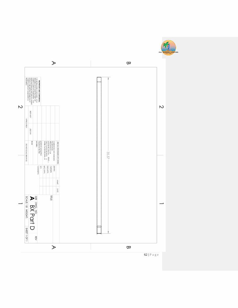
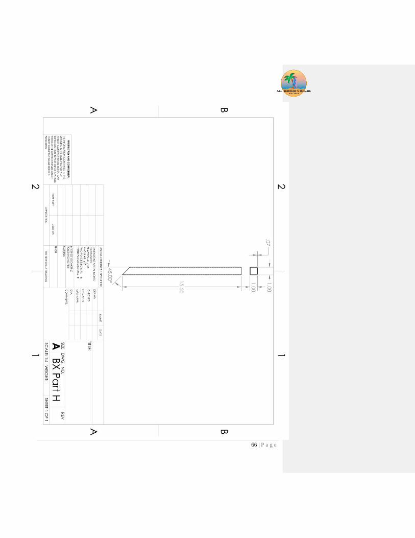
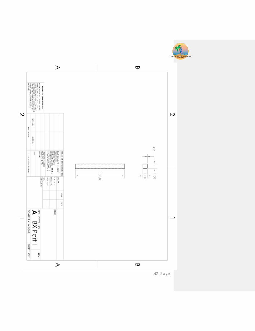
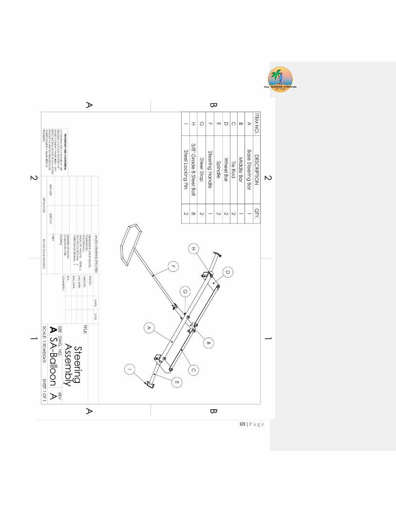
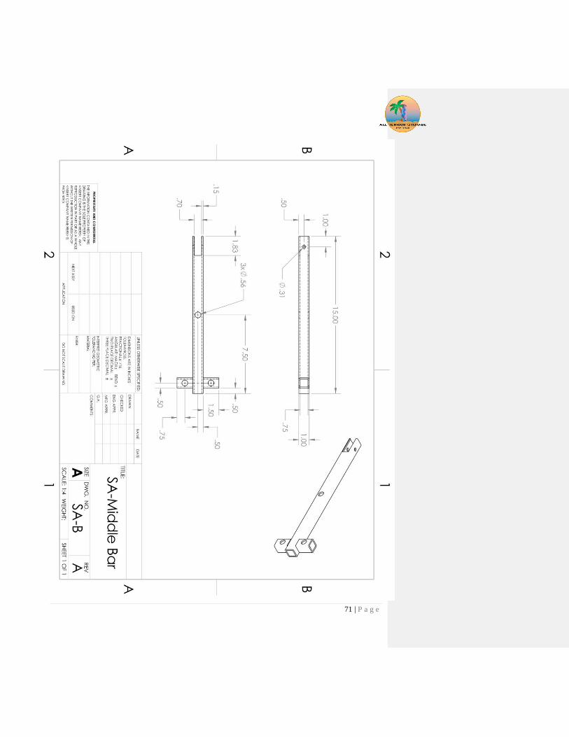
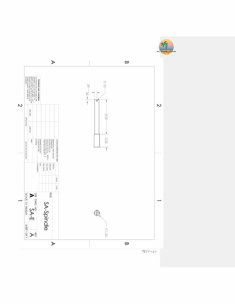
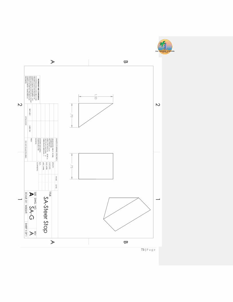
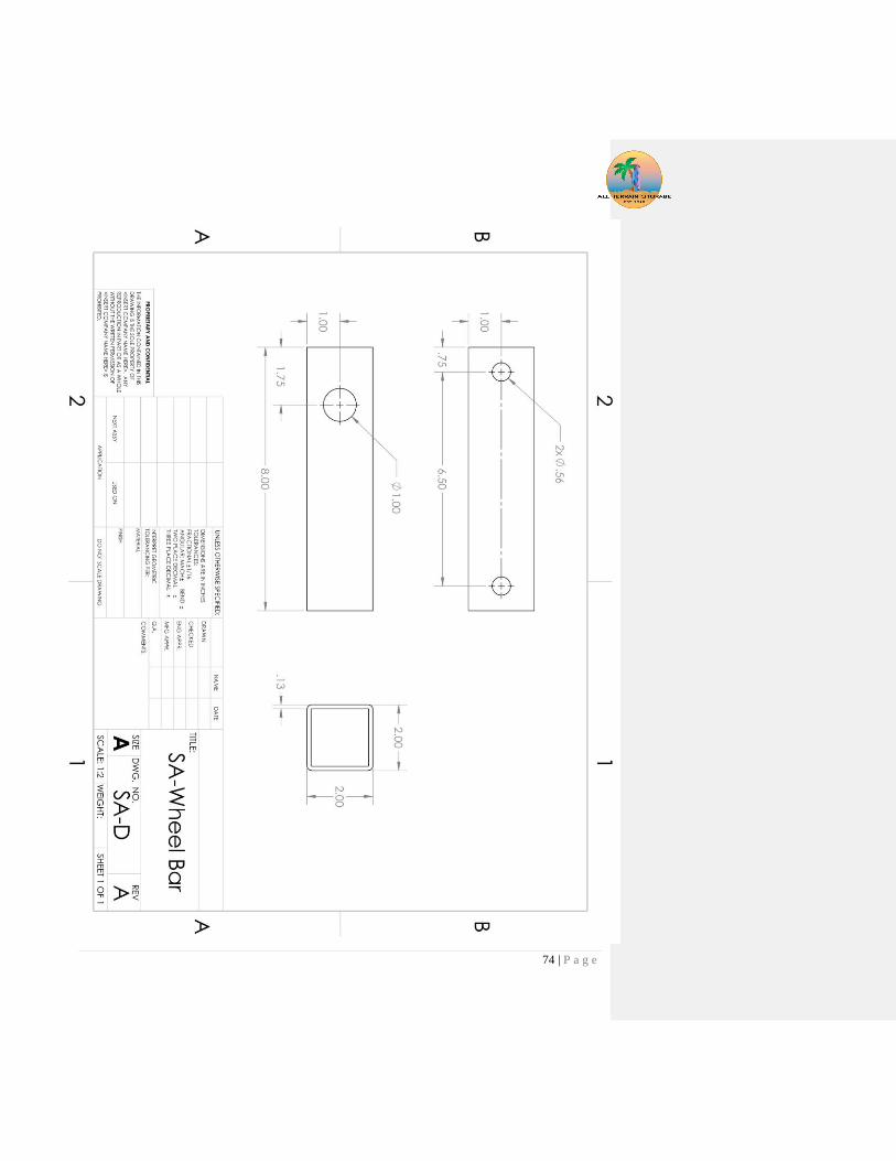
Appendix E. Complete Drawing Package
41 | P a g e

42 | P a g e
43 | P a g e

44 | P a g e
45 | P a g e

46 | P a g e

47 | P a g e
48 | P a g e

49 | P a g e
50 | P a g e
51 | P a g e
52 | P a g e
53 | P a g e

54 | P a g e

55 | P a g e
56 | P a g e

57 | P a g e

58 | P a g e

59 | P a g e

60 | P a g e

61 | P a g e
62 | P a g e

63 | P a g e

64 | P a g e

65 | P a g e
66 | P a g e
67 | P a g e

68 | P a g e
69 | P a g e

70 | P a g e
71 | P a g e
72 | P a g e
73 | P a g e
74 | P a g e
75 | P a g e
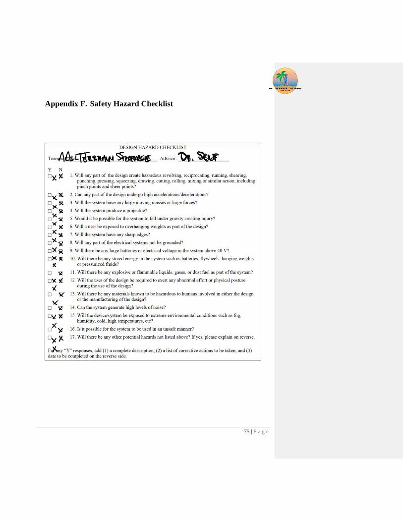
Appendix F. Safety Hazard Checklist

76 | P a g e
Appendix G. Gantt Chart

77 | P a g e
Appendix H. DVPR
78 | P a g e
Appendix I. Beam in Bending Stress Calculations
79 | P a g e
Wheel axel calculation modeled as a cantilever beam.

80 | P a g e

81 | P a g e
Appendix J. Material Selection
Mobile Surfboard Rack – Materials Selection Report
Materials Engineering Consulting Group
March 14th, 2018
Chase Cooper

82 | P a g e
Project Background
Senior Project group consisting of Ben Kennedy and
colleagues is designing a novel rolling surfboard rack.
This design will be capable of storing several
surfboards and wetsuits at one time. After completing
the model of the surfboard rack, the group will order
suitable materials and construct it at Cal Poly. The
material necessary for construction must meet several
design criteria in order for the build to be successful.
Materials Engineering Problem Statement
The Senior Project group needs to select a material for the construction of a surfboard
rack. The objective of the material selection is to maximize durability, while also
minimizing cost and weight. Multiple parameters will be considered when quantifying
durability. Selection is constrained to materials that have high resistance to corrosion
including in the presence of saltwater, are able to support large loads (~350lb), and can
be easily manufactured into the final design.
Deliverables
● Recommend suitable materials
○ Provide pros and cons for each candidate with design constraints and cost in mind
● Identify suitable material forms, vendors, and pricing for the top material candidates
Deadline
● Materials suggestions and report shall be completed by March 8th, 2018
Client Information
Ben-Kennedy
Consultants Contacts
Chase Cooper
(916)-622-6075
*Photo above is open source with no copyright

83 | P a g e
Executive Summary
Overall, the 6061 T6 Aluminum is the most suitable material for the application of a surfboard
rack. It has a combination of high strength, low cost and low density which makes it the best
performance material for the price. The overall corrosion resistance of 6061 T6 Aluminum is
excellent and is acceptable under the light salt water exposure from the surfboards. The material
is easily machinable, weldable, and is available in a variety of forms. In comparison to other
candidates, the aluminum 6061 has a lower young’s modulus, tensile strength, and corrosion
resistance. If stiffness is highly important, stainless steel may be a better option.
Materials Selection Details
The following section details the materials selection methodology utilized to determine
the recommended candidate for the surfboard rack.
Resistance to Environmental Degradation - Resistance to Environmental Degradation - Since the
material in this application will be repeatedly exposed to air and will have some exposure to
saltwater, it is important that the materials has a high general corrosion resistance (air, UV rays)
and a fairly good resistance to salt water.
Processing and Machinability – The form of the material must be in the shape of rods, bars,
or tubes.
Strength – The surfboard rack must be able to withstand loads of up to 300 pounds for
extended periods of time. The yield strength of the material will be used to determine the
strength of each material since it is not desirable for the rack to deform at all. The young’s
modulus of each material will also be considered in the selection.
Cost – Since funds are limited, cost will be factored into the final selection of the material
Weight – The surfboard rack should be able to be transported via the wheels so minimizing weight
is an objective of the selection

84 | P a g e
Candidate Identification and Down-Selection
After setting these objectives and constraints, we used CES materials selector software to find
materials that meet the design criteria. The selection was narrowed down to 3 base candidates
of different properties: Aluminum, Stainless Steel, and Titanium. After selecting these
materials, material Data was gathered for these materials and compiled in Table I.
Table 1: Data for the most viable materials for surfboard rack. Data obtained from CES and vendor websites
Material Corrosion
Resist
(x/10) [1]
Yield(MPa)
[2]
Young’s
Modulus(GPa)
[1]
Price per
foot Rod
(0.5 inch
Diameter
)
[2]
Density(g/cm3)
[1]
Form
Available
304
Stainless
Steel
9 205 190 2-10 8 Rod, Tube,
Rectangular
tube….
316
Stainless
Steel
10 205 185 3-10 8 Rod, Tube,
Rectangular
tube….
6063
Aluminum
T5
8 110 70 1.5-2 2.7 Rod, Tube,
Rectangular
tube….
6061
Aluminum
T6
8 240 70 1.5-2 2.7
Titanium 10 275 100 15-20 4.5 Rod, Tube,
Rectangular
tube….
In terms of properties, titanium has the highest yield strength, large modulus, and high
corrosion resistance while having low density. However, Titanium is very expensive which
takes it out of consideration for the surfboard rack which will require a fair amount of
material.
Of the stainless steels and aluminums commercially available, 6061 Al, 6063 Al, 304 Stainless
Steel, and 316 Stainless Steel were chosen as specific material candidates. Further research was
done on the material of current surfboard and other sports racks and these alloys commonly
appeared on the list of materials, with aluminum appearing quite often. One notable product on
Store Your Board [3] is made of 6061 T6 Aluminum and has received positive reviews from the
customers. Some products were made of low carbon steel but are susceptible to corrosion over
time.

85 | P a g e
Strength Comparison
The yield strength of the materials is generally the same excluding the 6063 Al which has a
significantly lower yield strength. The stainless steels do have a much higher ultimate tensile
strength than the aluminums, meaning they will work harden to a higher strength before
fracturing. Many, of the vendors sell the stainless steel annealed which is why the yield strength is
low so it may be possible to find a higher strength stainless steel if sold as cold worked. The
stainless steel has a much higher yield strength than aluminum, by a factor of 3. However, the
modulus of aluminum will most likely be sufficient for this application.
Corrosion Comparison
All the materials presented are highly corrosion resistant and will likely not degrade with exposure
to air. The stainless steels stand out due to their excellent resistance to saltwater corrosion. They
are specifically used in marine applications for extended periods of saltwater exposure. The
aluminum materials are also resistant to saltwater but aren’t intended for long term saltwater
exposure. Since the exposure to saltwater in this application is minimal, only being exposed to
surfboards after use, aluminum provides sufficient corrosion resistance for long term durability.
Processing and Machining
All the selected materials easily weldable and machinable. The only main difference is that
since 6063 Aluminum is softer it is easier to form other shapes via extrusion and other
forming techniques.
Other Considerations
Aluminum has about a third the density of steel which would significantly decrease the total
weight of the surfboard rack. In addition, aluminum is much cheaper than stainless steel.
Specifically, the price of stainless steel increases when trying to purchase in hollow form, likely
due to the difficulty of forming steel materials.
Final Recommendation and Closing remarks
Aluminum 6061 T6 aluminum alloy should be chosen for this application. For longest durability,
consider trying to keep the surface of the material relatively dry. If stiffness of material is an
issue, consider using stainless steel.
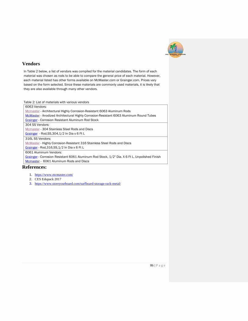
86 | P a g e
Vendors
In Table 2 below, a list of vendors was compiled for the material candidates. The form of each
material was chosen as rods to be able to compare the general price of each material. However,
each material listed has other forms available on McMaster.com or Grainger.com. Prices vary
based on the form selected. Since these materials are commonly used materials, it is likely that
they are also available through many other vendors.
Table 2: List of materials with various vendors
6063 Vendors:
Mcmaster - Architectural Highly Corrosion-Resistant 6063 Aluminum Rods
McMaster - Anodized Architectural Highly Corrosion-Resistant 6063 Aluminum Round Tubes
Grainger - Corrosion Resistant Aluminum Rod Stock
304 SS Vendors:
Mcmaster - 304 Stainless Steel Rods and Discs
Grainger - Rod,SS,304,1/2 In Dia x 6 Ft L
316L SS Vendors:
McMaster - Highly Corrosion-Resistant 316 Stainless Steel Rods and Discs
Grainger - Rod,316,SS,1/2 In Dia x 6 Ft L
6061 Aluminum Vendors:
Grainger - Corrosion Resistant 6061 Aluminum Rod Stock, 1/2" Dia. X 6 Ft L, Unpolished Finish
Mcmaster - 6061 Aluminum Rods and Discs
References:
1. https://www.mcmaster.com/
2. CES Edupack 2017
3. https://www.storeyourboard.com/surfboard-storage-rack-metal/

87 | P a g e
Appendix K. Cost Analysis

88 | P a g e
Appendix L. Failure Modes & Effects Analysis

89 | P a g e
Appendix M. Operators’ Manual This user manual is written to aid in the operation of the product safely.
Use
The purpose of the surf board cart is to transport and store the contents that Ampsurf stores in their trailer
to and from events.
Loading
Manually loading the carts with contents is required.
Warning: Lifting heavy objects onto high storage areas of the carts can cause injury to the user.
Caution is advised when lifting heavy objects.
In order to fully use the surf board carts storage ability surfboards must be loaded with fins in opposite
directions as shown below.
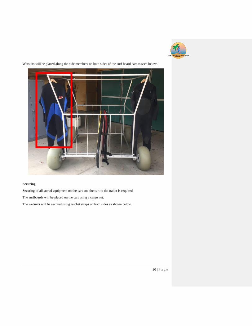
90 | P a g e
Wetsuits will be placed along the side members on both sides of the surf board cart as seen below.
Securing
Securing of all stored equipment on the cart and the cart to the trailer is required.
The surfboards will be placed on the cart using a cargo net.
The wetsuits will be secured using ratchet straps on both sides as shown below.
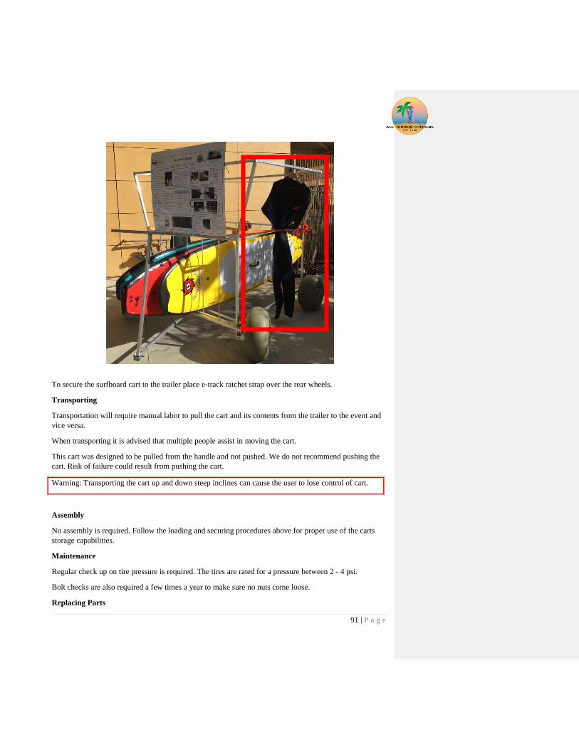
91 | P a g e
To secure the surfboard cart to the trailer place e-track ratchet strap over the rear wheels.
Transporting
Transportation will require manual labor to pull the cart and its contents from the trailer to the event and
vice versa.
When transporting it is advised that multiple people assist in moving the cart.
This cart was designed to be pulled from the handle and not pushed. We do not recommend pushing the
cart. Risk of failure could result from pushing the cart.
Warning: Transporting the cart up and down steep inclines can cause the user to lose control of cart.
Assembly
No assembly is required. Follow the loading and securing procedures above for proper use of the carts
storage capabilities.
Maintenance
Regular check up on tire pressure is required. The tires are rated for a pressure between 2 - 4 psi.
Bolt checks are also required a few times a year to make sure no nuts come loose.
Replacing Parts

92 | P a g e
To replace a part remove it from the cart using the appropriate tools described above while following the
proper procedures.