
Goldbach Seminar: Converged Media - Erfolgreich im Social Web kommunizieren

www.agru.at
AGRU Kunststofftechnik GmbHIng.-Pesendorfer-Straße 314540 Bad Hall, Austria
T. +43 7258 7900F. +43 7258 790 - [email protected]
AG
RU
LIN
E
0117
AGRULINE
PIPING SYSTEMS FOR NATURAL GAS, WATER & SEWAGE
ROHRSYSTEME FÜR GAS, WASSER & ABWASSER
ENDE
Ihr Fachhändler / Your distributor:
Subject to errors of typesetting, misprints and modifications. Illustrations are generic and for reference only.
Satzfehler, Druckfehler und Änderungen vorbehalten.Abbildungen sind teilweise Symbolfotos.
Piping SystemsAGRULINE | INDUSTRIAL | PURAD | AGRUSAN/AGRUAIR
Semi-Finished ProductsSHEETS | ROUND BARS | RODS
Concrete ProtectionSURE GRIP | ULTRA GRIP | HYDROCLICK
Lining SystemsGEOMEMBRANES | AUSTROPLAN - ROOF LINER AGRUFLEX - TUNNEL LINER

www.agru.at
OUR PRODUCTSARE AS MANIFOLDAS YOUR DEMANDS.
2
Seit 1948 erfolgreich
AGRU liefert Kunststofftechnik, die Kunden aus unter-schiedlichen Industriebereichen weltweit erfolgreich macht. Als zuverlässiger, erfahrener Lieferant bieten wir vom Halbzeug bis zum technologisch optimierten Spritzgussformteil alles aus einer Hand. Wir kennen die Herausforderungen aus tausenden Projekten und entwickeln unsere Produkte und Dienstleistungen lau-fend weiter. Kompromisslose Qualität, herausragender Kundennutzen und hohe Betriebssicherheit sind dabei unsere Maximen. Maßgeschneiderte Kundenlösungen und anwendungsorientierte Neuentwicklungen rea-lisieren wir mit höchster Flexibilität - präzise und kos-tengünstig. Unsere engagierten Mitarbeiter mit Kunst-stoffkompetenz machen AGRU zu einem erfolgreichen Global Player.
Alles aus einer Hand anzubieten, unterscheidet uns von Vielen. Wir verarbeiten ausschließlich hochwertige, thermoplastische Kunststoffe. Und wenn es um Lö-sungskompetenz bei Materialauswahl und Verlegung geht, sind wir Ihr bester Ansprechpartner.
The Plastics Experts.
Successful since 1948 AGRU supplies the plastics technology that makes cus-tomers from all over the world successful in their wide-ly differing industries. As a reliable, experienced sup-plier we offer everything from semi-finished products through to technologically optimised injection moul-dings, all from a single source. We handle the challen-ges from thousands of projects and evolve our products and services on a rolling basis. Uncompromising quali-ty, outstanding customer benefit and high operational dependability are our maxims. We implement custom solutions and application-oriented new developments with the highest flexibility - with precision and econo-mically. Our dedicated employees with plastics experti-se make AGRU successful as a global player.
Our ability to supply everything from a single source sets us apart. We use only top-grade thermoplastic polymers as our raw materials. When it comes to ap-plication-technical consulting, we are your best partner in the field.
The Plastics Experts.

3
AGRU PLANTS IN 5 COUNTRIES
AUSTRIA | GERMANY | POLAND
AGRU KUNSTSTOFFTECHNIKAUSTRIA
AGRU OBERFLÄCHENTECHNIKAUSTRIA
AGRU-FRANKGERMANY
TWSPOLAND
AGRU AMERICAFERNLEY, NV/USA
AGRU AMERICAGEORGETOWN, SC/USA
AGRU AMERICAANDREWS, SC/USA
TAICANG AGRU PLASTICSCHINA
4
Zulassungen / Certifications
INDUSTRIE INDUSTRIALPIPING SYSTEMSROHRSYSTEME / PIPING SYSTEMS
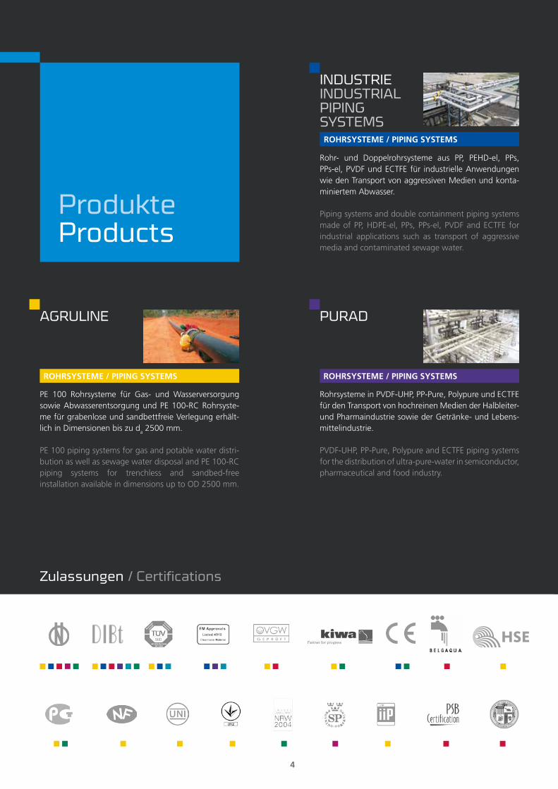
Rohr- und Doppelrohrsysteme aus PP, PEHD-el, PPs, PPs-el, PVDF und ECTFE für industrielle Anwendungen wie den Transport von aggressiven Medien und konta-miniertem Abwasser.
Piping systems and double containment piping systems made of PP, HDPE-el, PPs, PPs-el, PVDF and ECTFE for industrial applications such as transport of aggressive media and contaminated sewage water.
ROHRSYSTEME / PIPING SYSTEMS
PE 100 Rohrsysteme für Gas- und Wasserversorgung sowie Abwasserentsorgung und PE 100-RC Rohrsyste-me für grabenlose und sandbettfreie Verlegung erhält-lich in Dimensionen bis zu da 2500 mm.
PE 100 piping systems for gas and potable water distri-bution as well as sewage water disposal and PE 100-RC piping systems for trenchless and sandbed-free installation available in dimensions up to OD 2500 mm.
AGRULINE
ROHRSYSTEME / PIPING SYSTEMS
Rohrsysteme in PVDF-UHP, PP-Pure, Polypure und ECTFE für den Transport von hochreinen Medien der Halbleiter- und Pharmaindustrie sowie der Getränke- und Lebens-mittelindustrie.
PVDF-UHP, PP-Pure, Polypure and ECTFE piping systems for the distribution of ultra-pure-water in semiconductor, pharmaceutical and food industry.
PURAD
ProdukteProducts
5
BETONSCHUTZPLATTEN / CONCRETE PROTECTIVE LINERS
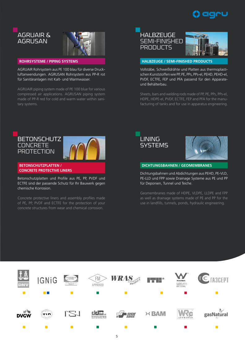
Betonschutzplatten und Profile aus PE, PP, PVDF und ECTFE sind der passende Schutz für Ihr Bauwerk gegen chemische Korrosion.
Concrete protective liners and assembly profiles made of PE, PP, PVDF and ECTFE for the protection of your concrete structures from wear and chemical corrosion.
BETONSCHUTZCONCRETE PROTECTION
DICHTUNGSBAHNEN / GEOMEMBRANES
Dichtungsbahnen und Abdichtungen aus PEHD, PE-VLD, PE-LLD und FPP sowie Drainage Systeme aus PE und PP für Deponien, Tunnel und Teiche.
Geomembranes made of HDPE, VLDPE, LLDPE and FPP as well as drainage systems made of PE and PP for the use in landfills, tunnels, ponds, hydraulic engineering.
LININGSYSTEMS
AGRUAIR &AGRUSAN
ROHRSYSTEME / PIPING SYSTEMS
AGRUAIR Rohrsystem aus PE 100 blau für diverse Druck-luftanwendungen. AGRUSAN Rohrsystem aus PP-R rot für Sanitäranlagen mit Kalt- und Warmwasser.
AGRUAIR piping system made of PE 100 blue for various compressed air applications. AGRUSAN piping system made of PP-R red for cold and warm water within sani-tary systems.
HALBZEUGE / SEMI-FINISHED PRODUCTS
Vollstäbe, Schweißdrähte und Platten aus thermoplasti-schen Kunststoffen wie PP, PE, PPs, PPs-el, PEHD, PEHD-el, PVDF, ECTFE, FEP und PFA passend für den Apparate- und Behälterbau.
Sheets, bars and welding rods made of PP, PE, PPs, PPs-el, HDPE, HDPE-el, PVDF, ECTFE, FEP and PFA for the manu-facturing of tanks and for use in apparatus engineering.
HALBZEUGESEMI-FINISHED PRODUCTS

6
Innovation sichert Erfolg
Forschung und Entwicklung haben einen sehr hohen Stellenwert im Unternehmen. Ziel der Forschung ist der absolute Kundennutzen im Sinne kontinuierlicher Ver-besserung und neuer Marktanforderungen. Die Mission erster zu sein.Europas erster Produzent von Formteilen im Spritzguss. Die weltweit erste Kalandrierung von extrabreiten Dich-tungsbahnen. AGRU setzt nun mit einem Reinraum-werk für Reinstmedien-Rohrsysteme neue Maßstäbe.
Innovation - the key to success
AGRU‘s plastics engineers are focused on the future. Only those who today are dealing with the customer- and target-group-specific requirements of tomorrow will be successful in the future.
We claim to be the first.Europe’s first to produce fittings in injection moulds; the world‘s first to calender liners many meters wide. Once again the company has set new standards by building a clean-room plant for ultra-pure media piping systems.
GROUND-BREAKING INNOVATIONS HAVE BEEN A HALLMARK OF AGRU SINCE ITS EARLIEST DAYS. z
The Plastics Experts.

7
AGRUIS KNOWN FOR ITS HIGHQUALITY STANDARDSAROUND THE WORLD.
Qualität
Kompromisslose Qualität, herausragender Kundennut-zen und hohe Betriebssicherheit sind unsere Maximen. In mehr als 50 Jahren hat AGRU einen Pool an Fach-wissen aufgebaut, das in der Branche einmalig ist. Die-se „Lebenserfahrung“ fließt in anwendungsorientierte Innovation, hochtechnologische Produktion sowie her-ausragende Service- und Logistikleistungen ein. Wir sind stolz auf viele nationale und internationale Zertifikate, Zulassungen und unser nach ISO 9001:2008 zertifiziertes Qualitätssystem – im Sinne unserer Kunden für weltweiten Einsatz.
Quality
Operational reliability, on-time delivery and maximum customer benefit are our maxims. Over more than 50 years, the plastics experts have accumulated a wealth of expertise unique in the industry. This lifetime of experi-ence flows into application-oriented innovation, high-tech production and outstanding service and logistics performance.
We are proud of our numerous national and interna-tional certificates, approvals and certified quality system ISO 9001:2008 – for our customers and for worldwide application.

8
Zuverlässigkeit
Unterschiedliche Werkstoffe, Technologien und Produkte sowie ein weltumspannen-des Partnernetzwerk machen AGRU zum zuverlässigen Komplettanbieter. Vor allem für Großprojekte und Sonderlösungen bietet AGRU damit seinen Kunden einen One-Stop-Shop. AGRU ist ein Synonym für Kundennutzen und dafür bekannt, die Kun-denwünsche effizient, kostengünstig und mit höchster Flexibilität zu erfüllen. Maßge-schneiderte, kunden orientierte technische Lösungen, „Out-of-the-box-Denken“ und jahrzehntelange Kunststofferfahrung sind dafür notwendig.
Reliability
Different materials, technologies and products plus a worldwide network of partners all contribute to making AGRU a single-source supplier. For large-scale projects and special solutions in particular, AGRU is able to offer its customers a one-stop shop. AGRU has built a reputation for satisfying its customers‘ wishes efficiently, cost-effectively and with superlative flexibility. Customer-oriented technical solutions, the ability to think outside the box and decades of hands-on experience are what it takes.
AGRU - A TRUSTED PARTNER.
The Plastics Experts.

9
Service
Die Wirtschaftlichkeit einer technischen Lösung ent-scheidet sich oft beim eingesetzten Werkstoff. Nur wenn das Ausgangsmaterial perfekt an die Einsatzbe-dingungen angepasst ist, können Chemikalien- und Temperaturbeständigkeit sowie die physische Belast-barkeit voll erfüllt werden. Die anwendungsspezifische Materialauswahl ist eine Kernkompetenz von AGRU. Als professioneller Ansprechpartner rund ums Thema Kunststoff zeigt AGRU die wirtschaftlichste Lösung für jede noch so große Herausforderung auf.
Service
Very often, the material used turns out to be definitive in terms of the ultimate profitability of an engineering solution. Only if the raw material is perfectly matched to the real-world conditions of use can physical toughness and resistance to chemicals and temperature effects be fully to specification. Application-specific material selec-tion is one of AGRU‘s core competences. As a profes-sional partner for everything associated with plastics, AGRU can point out the most economical solution for any problem, no matter how big the challenge.
MAXIMUM CUSTOMER BENEFIT.
10
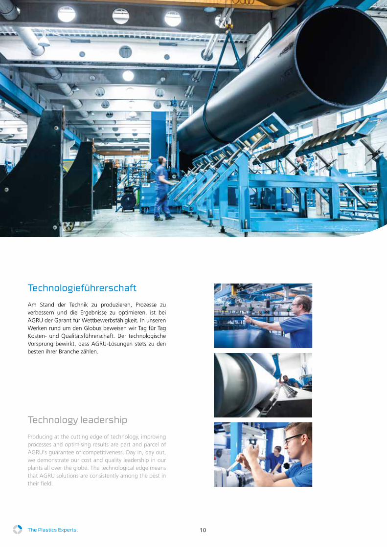
Technology leadership
Producing at the cutting edge of technology, improving processes and optimising results are part and parcel of AGRU‘s guarantee of competitiveness. Day in, day out, we demonstrate our cost and quality leadership in our plants all over the globe. The technological edge means that AGRU solutions are consistently among the best in their field.
Technologieführerschaft
Am Stand der Technik zu produzieren, Prozesse zu verbessern und die Ergebnisse zu optimieren, ist bei AGRU der Garant für Wettbewerbsfähigkeit. In unseren Werken rund um den Globus beweisen wir Tag für Tag Kosten- und Qualitätsführerschaft. Der technologische Vorsprung bewirkt, dass AGRU-Lösungen stets zu den besten ihrer Branche zählen.
The Plastics Experts.
Inhaltsverzeichnis
Mat
eria
leig
ensc
haft
enK
alku
latio
nsric
htlin
ien
Verb
indu
ngst
echn
ikVe
rlege
richt
linie
nN
orm
en u
nd Z
ulas
sung
en
11
A Materialeigenschaften 13
B Kalkulationsrichtlinien 27
C Verbindungstechnik 47
D Verlegerichtlinien 77
E Normen und Zulassungen 91

Mat
eria
leig
ensc
haft
enK
alku
latio
nsric
htlin
ien
Verb
indu
ngst
echn
ikVe
rlege
richt
linie
nN
orm
en u
nd Z
ulas
sung
en
12

Materialeigenschaften
Mat
eria
leig
ensc
haf
ten
Kal
kula
tions
richt
linie
nVe
rbin
dung
stec
hnik
Verle
geric
htlin
ien
Nor
men
und
Zul
assu
ngen
13
Mat
eria
leig
ensc
haf
ten
1 Allgemeine Eigenschaften 15
2 Werkstoffspezifische Eigenschaften 17
3 Vergleich Druckklassen 23
4 Beständigkeit von Polyethylen 24

Mat
eria
leig
ensc
haf
ten
Kal
kula
tions
richt
linie
nVe
rbin
dung
stec
hnik
Verle
geric
htlin
ien
Nor
men
und
Zul
assu
ngen
14
Materialeigenschaften
Mat
eria
leig
ensc
haf
ten
Kal
kula
tions
richt
linie
nVe
rbin
dung
stec
hnik
Verle
geric
htlin
ien
Nor
men
und
Zul
assu
ngen
15
1 Allgemeine Eigenschaften
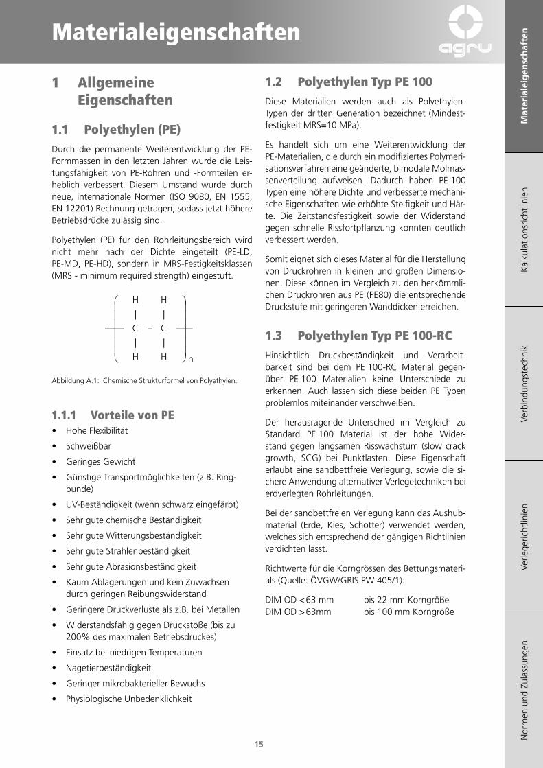
1.1 Polyethylen (PE)Durch die permanente Weiterentwicklung der PE-Formmassen in den letzten Jahren wurde die Leis-tungsfähigkeit von PE-Rohren und -Formteilen er-heblich verbessert. Diesem Umstand wurde durch neue, internationale Normen (ISO 9080, EN 1555, EN 12201) Rechnung getragen, sodass jetzt höhere Betriebsdrücke zulässig sind.
Polyethylen (PE) für den Rohrleitungsbereich wird nicht mehr nach der Dichte eingeteilt (PE-LD, PE-MD, PE-HD), sondern in MRS-Festigkeitsklassen (MRS - minimum required strength) eingestuft.
−
HH
CC
HH
||
||
n
Abbildung A.1: Chemische Strukturformel von Polyethylen.
1.1.1 Vorteile von PE• Hohe Flexibilität
• Schweißbar
• Geringes Gewicht
• Günstige Transportmöglichkeiten (z.B. Ring-bunde)
• UV-Beständigkeit (wenn schwarz eingefärbt)
• Sehr gute chemische Beständigkeit
• Sehr gute Witterungsbeständigkeit
• Sehr gute Strahlenbeständigkeit
• Sehr gute Abrasionsbeständigkeit
• Kaum Ablagerungen und kein Zuwachsen durch geringen Reibungswiderstand
• Geringere Druckverluste als z.B. bei Metallen
• Widerstandsfähig gegen Druckstöße (bis zu 200% des maximalen Betriebsdruckes)
• Einsatz bei niedrigen Temperaturen
• Nagetierbeständigkeit
• Geringer mikrobakterieller Bewuchs
• Physiologische Unbedenklichkeit
1.2 Polyethylen Typ PE 100Diese Materialien werden auch als Polyethylen- Typen der dritten Generation bezeichnet (Mindest-festigkeit MRS=10 MPa).
Es handelt sich um eine Weiterentwicklung der PE-Materialien, die durch ein modifiziertes Polymeri-sationsverfahren eine geänderte, bimodale Molmas-senverteilung aufweisen. Dadurch haben PE 100 Typen eine höhere Dichte und verbesserte mechani-sche Eigenschaften wie erhöhte Steifigkeit und Här-te. Die Zeitstandsfestigkeit sowie der Widerstand gegen schnelle Rissfortpflanzung konnten deutlich verbessert werden.
Somit eignet sich dieses Material für die Herstellung von Druckrohren in kleinen und großen Dimensio-nen. Diese können im Vergleich zu den herkömmli-chen Druckrohren aus PE (PE80) die entsprechende Druckstufe mit geringeren Wanddicken erreichen.
1.3 Polyethylen Typ PE 100‑RCHinsichtlich Druckbeständigkeit und Verarbeit-barkeit sind bei dem PE 100-RC Material gegen-über PE 100 Materialien keine Unterschiede zu erkennen. Auch lassen sich diese beiden PE Typen problemlos miteinander verschweißen.
Der herausragende Unterschied im Vergleich zu Standard PE 100 Material ist der hohe Wider-stand gegen langsamen Risswachstum (slow crack growth, SCG) bei Punktlasten. Diese Eigenschaft erlaubt eine sandbettfreie Verlegung, sowie die si-chere Anwendung alternativer Verlegetechniken bei erdverlegten Rohrleitungen.
Bei der sandbettfreien Verlegung kann das Aushub-material (Erde, Kies, Schotter) verwendet werden, welches sich entsprechend der gängigen Richtlinien verdichten lässt.
Richtwerte für die Korngrössen des Bettungsmateri-als (Quelle: ÖVGW/GRIS PW 405/1):
DIM OD < 63 mm bis 22 mm Korngröße DIM OD > 63mm bis 100 mm Korngröße
Mat
eria
leig
ensc
haf
ten
Kal
kula
tions
richt
linie
nVe
rbin
dung
stec
hnik
Verle
geric
htlin
ien
Nor
men
und
Zul
assu
ngen
16
PE100-RC bietet somit erweiterten Schutz gegen-über:
• Punktlasten,
• Rissinitiierung,
• Langsamem Risswachstum (SCG).
1.4 Vernetztes Polyethylen PE‑Xa
Der Werkstoff PE-Xa entsteht durch die peroxidische Vernetzung von Polyethylen bei hohem Druck. Hier-bei verbinden sich die einzelnen Moleküle des Poly-ethylens zu einem dreidimensionalen Netzwerk.
Dieses Vernetzungsverfahren sichert auch bei dick-wandigen Rohren eine gleichmäßige Vernetzung im gesamten Rohrquerschnitt.
Durch die Vernetzung kann PE-Xa nicht mehr auf-geschmolzen werden und wird deshalb auch als thermoelastisch bezeichnet. Er verbindet die guten Eigenschaften eines Thermoplasts mit denen eines Elastomers.
PE-Xa-Rohre haben folgende Eigenschaften:
• Kerbunempfindlichkeit
• Unempfindlichkeit gegenüber Punktlasten
• Spannungsrissunempfindlichkeit
• Höherer Widerstand gegen langsames Riss-wachstum
• Hoher Widerstand gegen Abrieb
• Hohe Kerbschlagzähigkeit bei extrem niedrigen Temperaturen
• Hohe Flexibilität bei tiefen Temperaturen
• Einsatz bis 95 °C Dauertemperatur
• Hohes Rückstellvermögen (Memory-Effekt)
Durch diese besonderen Werkstoffeigenschaften ergeben sich für die Praxis folgende praktische Vor-teile:
• Geeignet für grabenlose Verlegung und Sanierung (Rohre auf Ringbunden)
• Einsatz in Bergsenkungsgebieten
• Sehr hohe Betriebssicherheit
Deshalb wird PE-Xa vor allem dort eingesetzt, wo maximale Sicherheit gefragt ist, wie bei erdverleg-ten Gas- oder Trinkwasserleitungen.
1.4.1 Spannungsrissbeständigkeit
Bei Rohren aus nicht vernetzten Thermoplasten können durch punktförmige Lasten von außen (z.B. durch Steine) Spannungskonzentrationen und Über-dehnungen an der Rohrinnenseite entstehen. Diese können zu feinen Haarrissen im Gefüge (Span-nungsrisskorrosion) - und damit zum vorzeitigen Versagen der Rohre führen.
Durch die Vernetzung der Molekülketten bei PE-Xa ist der Widerstand gegen das Auftreten von Span-nungsrissen im Vergleich zu einem Rohr aus her-kömmlichen PE 100 wesentlich besser. Damit kön-nen Rohre aus PE-Xa ohne Sandbettung verlegt werden.
1.4.2 Kerbverhalten
Bei der Erdverlegung von Rohren und unter Um-ständen auch im späteren Betrieb können Kerben an der Rohroberfläche entstehen, die während der Betriebsdauer zu Rissen führen können.
PE-Xa hat einen wesentlich größeren Widerstand gegen die Kerbbildung und das Risswachstum als Rohre aus unvernetztem Polyethylen.
Rohre aus PE-Xa eignen sich deshalb besonders für grabenlose Verlegetechniken, bei welchen Beschä-digungen der Rohroberfläche kaum vermeidbar sind.
1.4.3 Verminderte Rissfortpflanzung
Als schnelle Rissfortpflanzung bezeichnet man die Neigung von Rohren bei hohen Drücken, kompres-siblen Medien und niedrigen Temperaturen im Fall von Rohrbeschädigungen in Längsrichtung schnell fortlaufende Risse über große Längen zu entwickeln.
Rohre aus PE-Xa zeigen selbst bei Temperaturen bis zu -50 °C und Drücken von bis zu 16 bar keine schnelle Rissfortpflanzung.
Materialeigenschaften
Mat
eria
leig
ensc
haf
ten
Kal
kula
tions
richt
linie
nVe
rbin
dung
stec
hnik
Verle
geric
htlin
ien
Nor
men
und
Zul
assu
ngen
17
2 Werkstoffspezifische Eigenschaften
2.1 PE 100 und PE 100‑RC
2.1.1 Materialeigenschaften
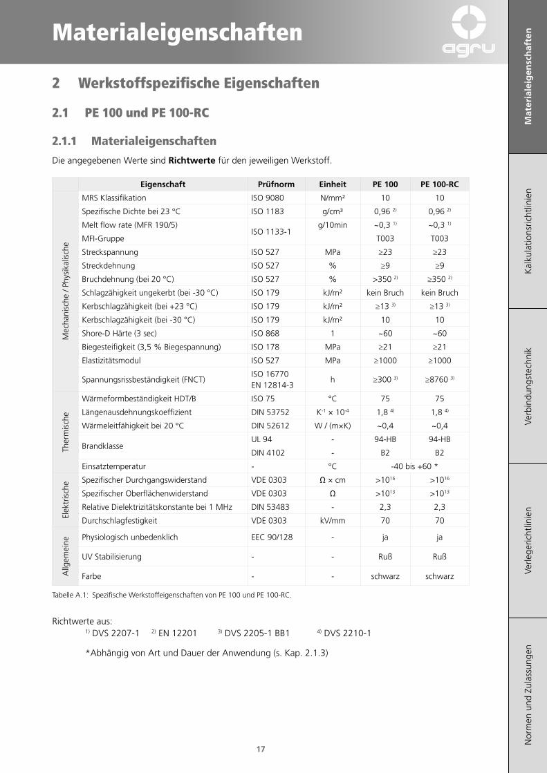
Die angegebenen Werte sind Richtwerte für den jeweiligen Werkstoff.
Eigenschaft Prüfnorm Einheit PE 100 PE 100‑RC
Mec
hani
sche
/ Ph
ysik
alis
che
MRS Klassifikation ISO 9080 N/mm² 10 10
Spezifische Dichte bei 23 °C ISO 1183 g/cm³ 0,96 2) 0,96 2)
Melt flow rate (MFR 190/5)ISO 1133-1
g/10min ~0,3 1) ~0,3 1)
MFI-Gruppe T003 T003
Streckspannung ISO 527 MPa ≥23 ≥23
Streckdehnung ISO 527 % ≥9 ≥9
Bruchdehnung (bei 20 °C) ISO 527 % >350 2) ≥350 2)
Schlagzähigkeit ungekerbt (bei -30 °C) ISO 179 kJ/m² kein Bruch kein Bruch
Kerbschlagzähigkeit (bei +23 °C) ISO 179 kJ/m² ≥13 3) ≥13 3)
Kerbschlagzähigkeit (bei -30 °C) ISO 179 kJ/m² 10 10
Shore-D Härte (3 sec) ISO 868 1 ~60 ~60
Biegesteifigkeit (3,5 % Biegespannung) ISO 178 MPa ≥21 ≥21
Elastizitätsmodul ISO 527 MPa ≥1000 ≥1000
Spannungsrissbeständigkeit (FNCT)ISO 16770EN 12814-3
h ≥300 3) ≥8760 3)
Ther
mis
che
Wärmeformbeständigkeit HDT/B ISO 75 °C 75 75
Längenausdehnungskoeffizient DIN 53752 K-1 × 10⁻⁴ 1,8 4) 1,8 4)
Wärmeleitfähigkeit bei 20 °C DIN 52612 W / (m×K) ~0,4 ~0,4
BrandklasseUL 94 - 94-HB 94-HB
DIN 4102 - B2 B2
Einsatztemperatur - °C -40 bis +60 *
Elek
tris
che Spezifischer Durchgangswiderstand VDE 0303 Ω × cm >1016 >1016
Spezifischer Oberflächenwiderstand VDE 0303 Ω >1013 >1013
Relative Dielektrizitätskonstante bei 1 MHz DIN 53483 - 2,3 2,3
Durchschlagfestigkeit VDE 0303 kV/mm 70 70
Allg
emei
ne
Physiologisch unbedenklich EEC 90/128 - ja ja
UV Stabilisierung - - Ruß Ruß
Farbe - - schwarz schwarz
Tabelle A.1: Spezifische Werkstoffeigenschaften von PE 100 und PE 100-RC.
Richtwerte aus: 1) DVS 2207-1 2) EN 12201 3) DVS 2205-1 BB1 4) DVS 2210-1
*Abhängig von Art und Dauer der Anwendung (s. Kap. 2.1.3)

Mat
eria
leig
ensc
haf
ten
Kal
kula
tions
richt
linie
nVe
rbin
dung
stec
hnik
Verle
geric
htlin
ien
Nor
men
und
Zul
assu
ngen
18
2.1.2 Zeitstandkurve
1 Jah
r
10 Ja
hre
25 Ja
hre
50 Ja
hre
10 °C
20 °C
30 °C
40 °C
50 °C
60 °C
70 °C
80 °C
100 J
ahre
1 10
Standzeit, t [h]
1
10
2
3
4
5
6
7
89
20
30
40
50
102 103 104 105 106
Verg
leic
hssp
annu
ng, σ
v [N
/mm
²]
Abbildung A.2: Zeitstandkurve PE 100 und PE 100-RC. (Quelle: DVS2205-1 BB1, EN ISO 15494:2013)
Materialeigenschaften
Mat
eria
leig
ensc
haf
ten
Kal
kula
tions
richt
linie
nVe
rbin
dung
stec
hnik
Verle
geric
htlin
ien
Nor
men
und
Zul
assu
ngen
19
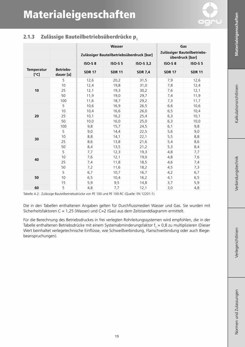
2.1.3 Zulässige Bauteilbetriebsüberdrücke pB
Wasser Gas
Zulässiger Bauteilbetriebsüberdruck [bar]Zulässiger Bauteilbetriebs‑
überdruck [bar]
ISO‑S 8 ISO‑S 5 ISO‑S 3,2 ISO‑S 8 ISO‑S 5
Temperatur [°C]
Betriebs‑dauer [a]
SDR 17 SDR 11 SDR 7,4 SDR 17 SDR 11
10
5 12,6 20,2 31,5 7,9 12,610 12,4 19,8 31,0 7,8 12,425 12,1 19,3 30,2 7,6 12,150 11,9 19,0 29,7 7,4 11,9
100 11,6 18,7 29,2 7,3 11,7
20
5 10,6 16,9 26,5 6,6 10,610 10,4 16,6 26,0 6,5 10,425 10,1 16,2 25,4 6,3 10,150 10,0 16,0 25,0 6,3 10,0
100 9,8 15,7 24,5 6,1 9,8
30
5 9,0 14,4 22,5 5,6 9,010 8,8 14,1 22,1 5,5 8,825 8,6 13,8 21,6 5,4 8,650 8,4 13,5 21,2 5,3 8,4
40
5 7,7 12,3 19,3 4,8 7,710 7,6 12,1 19,0 4,8 7,625 7,4 11,8 18,5 4,6 7,450 7,2 11,6 18,2 4,5 7,3
505 6,7 10,7 16,7 4,2 6,7
10 6,5 10,4 16,2 4,1 6,515 5,9 9,5 14,8 3,7 5,9
60 5 4,8 7,7 12,1 3,0 4,8
Tabelle A.2: Zulässige Bauteilbetriebsdrücke von PE 100 und PE 100-RC (Quelle: EN 12201-1).
Die in den Tabellen enthaltenen Angaben gelten für Durchflussmedien Wasser und Gas. Sie wurden mit Sicherheitsfaktoren C = 1,25 (Wasser) und C=2 (Gas) aus dem Zeitstanddiagramm ermittelt.
Für die Berechnung des Betriebsdruckes in frei verlegten Rohrleitungssystemen wird empfohlen, die in der Tabelle enthaltenen Betriebsdrücke mit einem Systemabminderungsfaktor fS = 0,8 zu multiplizieren (Dieser Wert beinhaltet verlegetechnische Einflüsse, wie Schweißverbindung, Flanschverbindung oder auch Biege-beanspruchungen).
Mat
eria
leig
ensc
haf
ten
Kal
kula
tions
richt
linie
nVe
rbin
dung
stec
hnik
Verle
geric
htlin
ien
Nor
men
und
Zul
assu
ngen
20
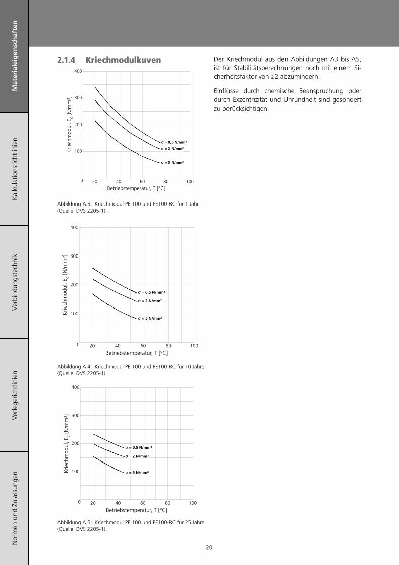
2.1.4 Kriechmodulkuven
Abbildung A.3: Kriechmodul PE 100 und PE100-RC für 1 Jahr (Quelle: DVS 2205-1).
Abbildung A.4: Kriechmodul PE 100 und PE100-RC für 10 Jahre (Quelle: DVS 2205-1).
Abbildung A.5: Kriechmodul PE 100 und PE100-RC für 25 Jahre (Quelle: DVS 2205-1).
Der Kriechmodul aus den Abbildungen A3 bis A5, ist für Stabilitätsberechnungen noch mit einem Si-cherheitsfaktor von ≥2 abzumindern.
Einflüsse durch chemische Beanspruchung oder durch Exzentrizität und Unrundheit sind gesondert zu berücksichtigen.
Betriebstemperatur, T [°C]
0
100
200
300
400
20 40 60 80 100
σ = 0,5 N/mm²
σ = 2 N/mm²
σ = 5 N/mm²
Krie
chm
odul
, EC [N
/mm
²]
Betriebstemperatur, T [°C]
0
100
200
300
400
20 40 60 80 100
σ = 0,5 N/mm²
σ = 2 N/mm²
σ = 5 N/mm²Krie
chm
odul
, EC [N
/mm
²]
Betriebstemperatur, T [°C]
0
100
200
300
400
20 40 60 80 100
σ = 0,5 N/mm²
σ = 2 N/mm²
σ = 5 N/mm²
Krie
chm
odul
, EC [N
/mm
²]
Materialeigenschaften
Mat
eria
leig
ensc
haf
ten
Kal
kula
tions
richt
linie
nVe
rbin
dung
stec
hnik
Verle
geric
htlin
ien
Nor
men
und
Zul
assu
ngen
21
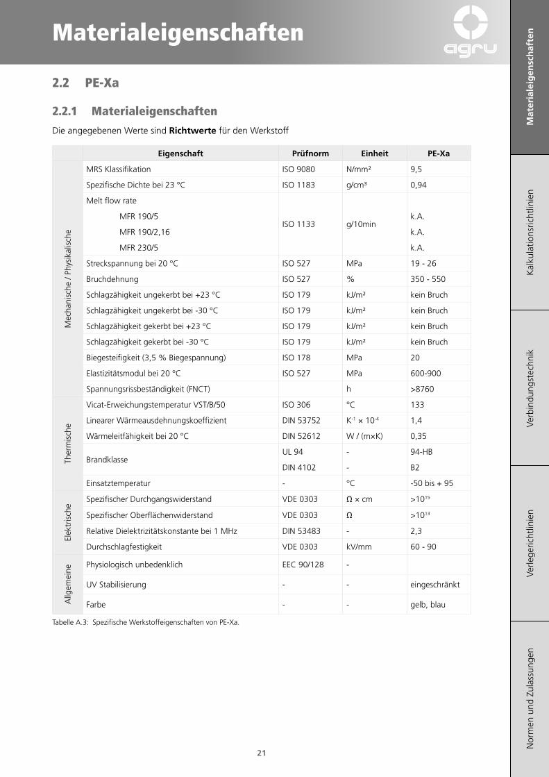
2.2 PE‑Xa
2.2.1 Materialeigenschaften
Die angegebenen Werte sind Richtwerte für den Werkstoff
Eigenschaft Prüfnorm Einheit PE‑Xa
Mec
hani
sche
/ Ph
ysik
alis
che
MRS Klassifikation ISO 9080 N/mm² 9,5
Spezifische Dichte bei 23 °C ISO 1183 g/cm³ 0,94
Melt flow rate
ISO 1133 g/10min MFR 190/5 k.A.
MFR 190/2,16 k.A.
MFR 230/5 k.A.
Streckspannung bei 20 °C ISO 527 MPa 19 - 26
Bruchdehnung ISO 527 % 350 - 550
Schlagzähigkeit ungekerbt bei +23 °C ISO 179 kJ/m² kein Bruch
Schlagzähigkeit ungekerbt bei -30 °C ISO 179 kJ/m² kein Bruch
Schlagzähigkeit gekerbt bei +23 °C ISO 179 kJ/m² kein Bruch
Schlagzähigkeit gekerbt bei -30 °C ISO 179 kJ/m² kein Bruch
Biegesteifigkeit (3,5 % Biegespannung) ISO 178 MPa 20
Elastizitätsmodul bei 20 °C ISO 527 MPa 600-900
Spannungsrissbeständigkeit (FNCT) h >8760
Ther
mis
che
Vicat-Erweichungstemperatur VST/B/50 ISO 306 °C 133
Linearer Wärmeausdehnungskoeffizient DIN 53752 K-1 × 10⁻⁴ 1,4
Wärmeleitfähigkeit bei 20 °C DIN 52612 W / (m×K) 0,35
BrandklasseUL 94 - 94-HB
DIN 4102 - B2
Einsatztemperatur - °C -50 bis + 95
Elek
tris
che
Spezifischer Durchgangswiderstand VDE 0303 Ω × cm >1015
Spezifischer Oberflächenwiderstand VDE 0303 Ω >1013
Relative Dielektrizitätskonstante bei 1 MHz DIN 53483 - 2,3
Durchschlagfestigkeit VDE 0303 kV/mm 60 - 90
Allg
emei
ne
Physiologisch unbedenklich EEC 90/128 -
UV Stabilisierung - - eingeschränkt
Farbe - - gelb, blau
Tabelle A.3: Spezifische Werkstoffeigenschaften von PE-Xa.
Mat
eria
leig
ensc
haf
ten
Kal
kula
tions
richt
linie
nVe
rbin
dung
stec
hnik
Verle
geric
htlin
ien
Nor
men
und
Zul
assu
ngen
22
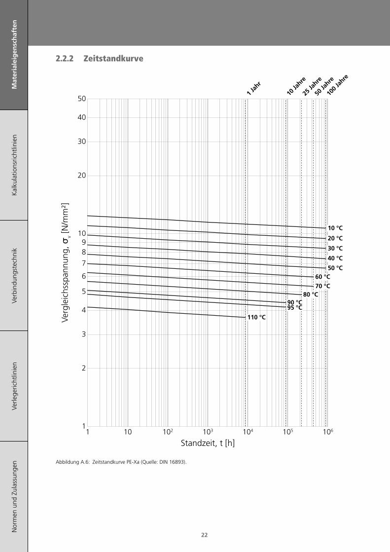
2.2.2 Zeitstandkurve
1 Jah
r
10 Ja
hre
25 Ja
hre
50 Ja
hre
10 °C
20 °C
30 °C
40 °C
50 °C60 °C
70 °C80 °C
90 °C95 °C
110 °C
100 J
ahre
1 10
Standzeit, t [h]
1
10
2
3
4
5
6
7
89
20
30
40
50
102 103 104 105 106
Verg
leic
hssp
annu
ng, σ
v [N
/mm
²]
Abbildung A.6: Zeitstandkurve PE-Xa (Quelle: DIN 16893).

Materialeigenschaften
Mat
eria
leig
ensc
haf
ten
Kal
kula
tions
richt
linie
nVe
rbin
dung
stec
hnik
Verle
geric
htlin
ien
Nor
men
und
Zul
assu
ngen
23
2.2.3 Bauteilbetriebsüberdruck pB
Zulässiger Bauteilbe‑triebsüberdruck [bar]
Wasser Gas
Tempera‑tur [°C]
Betriebs‑dauer [a]
SDR 11 / ISO‑S 5
10
1 17,9 11,25 17,5 10,9
10 17,4 10,925 17,2 10,850 17,1 10,7
100 17,0 10,6
20
1 15,8 9,95 15,5 9,7
10 15,4 9,625 15,2 9,550 15,1 9,4
100 15,0 9,4
30
1 14,0 8,85 13,8 8,6
10 13,7 8,625 13,5 8,450 13,4 8,4
100 13,3 8,3
40
1 12,5 7,85 12,2 7,6
10 12,1 7,625 12,0 7,550 11,9 7,4
100 11,8 7,4
50
1 11,1 6,95 10,9 6,8
10 10,8 6,825 10,7 6,750 10,6 6,6
100 10,5 6,6
60
1 9,9 6,25 9,7 6,1
10 9,7 6,125 9,5 5,950 9,5 5,9
70
1 8,9 5,65 8,7 5,4
10 8,6 5,425 8,5 5,350 8,5 5,3
80
1 8,0 5,05 7,8 4,9
10 7,7 4,825 7,6 4,8
901 7,2 4,55 7,0 4,4
10 6,9 4,3
951 6,8 4,35 6,6 4,1
Tabelle A.4: Zulässige Bauteilbetriebsdrücke von PE-Xa (Quelle: DIN 16893).
Die in den Tabellen enthaltenen Angaben gelten für Durchflussmedien Wasser und Gas. Sie wur-den mit Sicherheitsfaktoren C = 1,25 (Wasser) und C = 2 (Gas) aus dem Zeitstanddiagramm ermittelt.
3 Vergleich DruckklassenNachfolgender Vergleich stellt den Unterschied zwi-schen der SDR-Reihe, S-Reihe und PN-Druckklasse dar (gültig für 20 °C, 50 Jahre Lebensdauer und C = 1,25 (Wasser)).
SDR S
PN‑Druckklasse (Wasser)
PE100 / PE100‑RC
PE‑Xa PE 80
41 20 4 - 3,2
33 16 5 - 4
26 12,5 6,3 - 5
17 8 10 - 7,5
11 5 16 12,5 8
9 4 20 - 12,5
7,4 3,2 25 20 20
Tabelle A.5: Vergleich Druckklassen (Quelle: EN 12201-2, DVGW G400-1, DVGW G472).
Mat
eria
leig
ensc
haf
ten
Kal
kula
tions
richt
linie
nVe
rbin
dung
stec
hnik
Verle
geric
htlin
ien
Nor
men
und
Zul
assu
ngen
24
4 Beständigkeit von Polyethylen
4.1 Physikalische Beständigkeit
4.1.1 Physiologische Unbedenklichkeit
Polyethylen entspricht in seiner Zusammensetzung den einschlägigen lebensmittelrechtlichen Bestim-mungen (nach ÖNorm B 5014 Teil 1, BGA, KTW-Richtlinien).
PE-Rohre und -Formteile sind auf Trinkwassertaug-lichkeit nach DVGW Richtlinie W270 geprüft.
4.1.2 Verhalten bei Strahlenbelastung
Rohre aus Polyethylen können grundsätzlich im Be-reich energiereicher Strahlung eingesetzt werden. So haben sich Rohre aus PE seit vielen Jahren zur Ableitung radioaktiver Abwässer aus Heißlaboren und als Kühlwasserleitungen in der Kernenergie-technik bewährt.
Die üblichen radioaktiven Abwässer enthalten Quel-len für Beta- und Gammastrahlen. PE-Rohrleitungen werden selbst nach jahrelangem Einsatz nicht radio-aktiv.
Auch in Umgebung höherer Aktivitäten werden Rohre aus PE nicht geschädigt, wenn sie während ihrer gesamten Betriebszeit keine größere, gleich-mäßig verteilte Strahlendosis als <104 Gray enthal-ten.
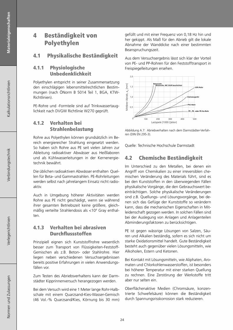
4.1.3 Verhalten bei abrasiven Durchflussstoffen
Prinzipiell eignen sich Kunststoffrohre wesentlich besser zum Transport von Flüssigkeiten-Feststoff-Gemischen als z.B. Beton- oder Stahlrohre. Hier liegen neben verschiedenen Versuchsergebnissen bereits positive Erfahrungen in vielen Anwendungs-fällen vor.
Zum Testen des Abriebsverhaltens kann der Darm-städter Kipprinnenversuch herangezogen werden.
Bei dem Versuch wird eine 1 Meter lange Rohr-Halb-schale mit einem Quarzsand-Kies-Wasser-Gemisch (46 Vol.-% Quarzsand/Kies, Körnung bis 30 mm)
gefüllt und mit einer Frequenz von 0,18 Hz hin und her gekippt. Als Maß für den Abrieb gilt die lokale Abnahme der Wanddicke nach einer bestimmten Beanspruchungszeit.
Aus dem Versuchsergebnis lässt sich klar der Vorteil von PE- und PP-Rohren für den Feststofftransport in Freispiegelleitungen ersehen.
Lastspiele [1000 Zyklen]100 200 300 400 5000
0,5
1,0
1,5
2,0
BetonrohrBetonrohr, MC-DUR beschichtet
GFK-Rohr
Steinzeugrohr
PVC-Rohr
PP-, PE- oder PE-Xa-Rohr
Mitt
lere
r A
brie
b, a
m [m
m]
Abbildung A.7: Abriebverhalten nach dem Darmstädter-Verfah-ren (DIN EN 295-3).
Quelle: Technische Hochschule Darmstadt
4.2 Chemische BeständigkeitIm Unterschied zu den Metallen, bei denen ein Angriff von Chemikalien zu einer irreversiblen che-mischen Veränderung des Materials führt, sind es bei den Kunststoffen in den überwiegenden Fällen physikalische Vorgänge, die den Gebrauchswert be-einträchtigen. Solche physikalische Veränderungen sind z.B. Quellungs- und Lösungsvorgänge, bei de-nen sich das Gefüge der Kunststoffe so verändern kann, dass die mechanischen Eigenschaften in Mit-leidenschaft gezogen werden. In solchen Fällen sind bei der Auslegung von Anlagen und Anlagenteilen Abminderungsfaktoren zu berücksichtigen.
PE ist gegen wässrige Lösungen von Salzen, Säu-ren und Alkalien beständig, sofern es sich nicht um starke Oxidationsmittel handelt. Gute Beständigkeit besteht auch gegenüber vielen Lösungsmitteln, wie Alkoholen, Estern und Ketonen.
Bei Kontakt mit Lösungsmitteln, wie Aliphaten, Aro-maten und Chlorkohlenwasserstoffen, ist besonders bei höherer Temperatur mit einer starken Quellung zu rechnen. Eine Zerstörung der Werkstoffe tritt aber nur selten ein.
Oberflächenaktive Medien (Chromsäure, konzen-trierte Schwefelsäure) können die Beständigkeit durch Spannungsrisskorrosion stark reduzieren.

Materialeigenschaften
Mat
eria
leig
ensc
haf
ten
Kal
kula
tions
richt
linie
nVe
rbin
dung
stec
hnik
Verle
geric
htlin
ien
Nor
men
und
Zul
assu
ngen
25
4.2.1 Laugen
4.2.1.1 Alkalilaugen
Wässrige Lösungen von Alkalien (z.B. Kalilauge, Na-tronlauge, ...) reagieren auch bei erhöhter Tempe-ratur und hohen Konzentrationen nicht mit PE und sind daher ohne Probleme in PE-Systemen einsetz-bar.
4.2.1.2 Natriumhypochlorit
Bei diesem Medium muss man bereits bei Raum-temperatur von einer bedingten Beständigkeit aus-gehen.
Bei höheren Temperaturen und einer Konzentration von > 3 mg/l ist PE nur noch für drucklose Rohrlei-tungssysteme geeignet.
4.2.1.3 Kohlenwasserstoffe
PE ist gegen Kohlenwasserstoffe (Benzin sowie an-dere Treibstoffe) bis zu Temperaturen von 40 °C für den Transport und 60 °C für die Lagerung dieser Medien beständig.
Erst bei Temperaturen von mehr als 60 °C ist PE nur bedingt beständig, da die Quellung >3 % beträgt.
4.2.2 Säuren
4.2.2.1 Schwefelsäure
Konzentrationen bis ca. 78 % verändern die Eigen-schaften von PE nur geringfügig. Konzentrationen über 85 % wirken bereits bei Raumtemperatur oxi-dierend.
4.2.2.2 Salzsäure, Flusssäure
Gegenüber konzentrierter Salzsäure und Flusssäure ist PE chemisch widerstandsfähig.
Es tritt jedoch ab einer Konzentration >20 % bei HCl und >40 % bei HF eine Diffusion auf, die zwar das Material in keiner Weise schädigt, dafür aber Sekundärschäden an umliegenden Stahlbauten ver-ursacht. Bei solchen Anwendungen haben sich Dop-pelrohrsysteme bewährt.
4.2.2.3 Salpetersäure
Höher konzentrierte Salpetersäure wirkt oxidierend auf PE, sodass mit einer Abnahme der mechani-schen Festigkeitseigenschaften zu rechnen ist.
4.2.2.4 Phosphorsäure
Gegenüber diesem Medium ist PE auch bei höheren Konzentrationen und bei erhöhten Temperaturen beständig.
Für nähere Informationen bezüglich der Bestän-digkeit unserer Produkte steht Ihnen unsere An-wendungstechnik gerne jederzeit zur Verfügung ([email protected]).

Mat
eria
leig
ensc
haf
ten
Kal
kula
tions
richt
linie
nVe
rbin
dung
stec
hnik
Verle
geric
htlin
ien
Nor
men
und
Zul
assu
ngen
26

Kalkulationsrichtlinien
Mat
eria
leig
ensc
haft
enK
alku
lati
on
sric
htl
inie
nVe
rbin
dung
stec
hnik
Verle
geric
htlin
ien
Nor
men
und
Zul
assu
ngen
27
1 SDR - Standard Dimension Ratio 29
2 S-Reihe 29
3 Bauteilbetriebsdruck 29
4 Rohrwanddicke 29
5 Beuldruck (Unterdruck) 30
6 Rohrquerschnitt 30
7 Hydraulische Verluste 31
8 Längenänderungen 36
9 Festpunktbelastung 36
10 Biegeschenkellängen 38
11 Rohrstützweiten 40
12 Ringsteifigkeit 42
13 Durchfluss (Nomogramm) 42
14 Berechnungshilfen 44

Mat
eria
leig
ensc
haft
enK
alku
lati
on
sric
htl
inie
nVe
rbin
dung
stec
hnik
Verle
geric
htlin
ien
Nor
men
und
Zul
assu
ngen
28

Kalkulationsrichtlinien
Mat
eria
leig
ensc
haft
enK
alku
lati
on
sric
htl
inie
nVe
rbin
dung
stec
hnik
Verle
geric
htlin
ien
Nor
men
und
Zul
assu
ngen
29
1 SDR - Standard Dimension Ratio
s
da
Abbilung B.1: Rohrabmessungen.
sd
SDR a=
Formel B.1: SDR.
da Außendurchmesser [mm]s Wanddicke [mm]SDR Außendurchmesser-Wandstärken-
Verhältnis [1]
2 S-Reihe
21−
=SDR
S
Formel B.2: S-Reihe.
S ISO S-Reihe [1]SDR Standard Dimension Ratio [1]
3 Bauteilbetriebsdruck
⋅⋅
( )120
−=
SDRcpB
σ
Formel B.3: Bauteilbetriebsdruck.
c minimaler Sicherheitsfaktor [1]pB Bauteilbetriebsdruck [bar]SDR Standard Dimension Ratio [1]σ Vergleichsspannung [N/mm²]
Minimaler Sicherheitsfaktor c [1]
Trinkwasser, Abwasser
Gas
PE 100, PE 100‑RC
1,25 2,0
PE‑Xa 1,25 2,0
Tabelle B.1: Minimale Sicherheitsfaktoren.
Vergleichsspannung siehe Kapitel A „Zeitstandkur-ve“.
4 RohrwanddickeFestigkeitsberechnungen für thermoplastische Kunststoffrohrleitungen sind grundsätzlich auf der Basis von Langzeitkennwerten vorzunehmen. Die Festigkeitswerte können, in Abhängigkeit von der Temperatur, aus den Zeitstandkurven (siehe Kapitel Materialeigenschaften) entnommen werden.
Nach der Ermittlung der rechnerischen Wanddicke muss die Ausführungswanddicke unter Berücksich-tigung der Nenndruckstufe bzw. SDR-Klasse be-stimmt werden. Wanddickenzuschläge (z.B. beim Einsatz von PE-Rohrleitung im Freien ohne UV-Schutz oder beim Transport abrasiver Stoffe) sind zu berücksichtigen.
⋅⋅
pdap
szul +
=20min σ
Formel B.4: Mindestwanddicke.
czul =σσ
Formel B.5: Zulässige Spannung.
c minimaler Sicherheitsfaktor [1]da Außendurchmesser [mm]p Betriebdruck [bar]smin Mindestwanddicke [mm]σ Vergleichsspannung [N/mm²]σzul zulässige Spannung [N/mm²]
Vergleichsspannung siehe Kapitel A „Zeitstand-kur-ve“.
Mat
eria
leig
ensc
haft
enK
alku
lati
on
sric
htl
inie
nVe
rbin
dung
stec
hnik
Verle
geric
htlin
ien
Nor
men
und
Zul
assu
ngen
30
Falls erforderlich kann aus dieser Formel auch die Vergleichsspannung σ bzw. der Betriebsdruck p er-rechnet werden.
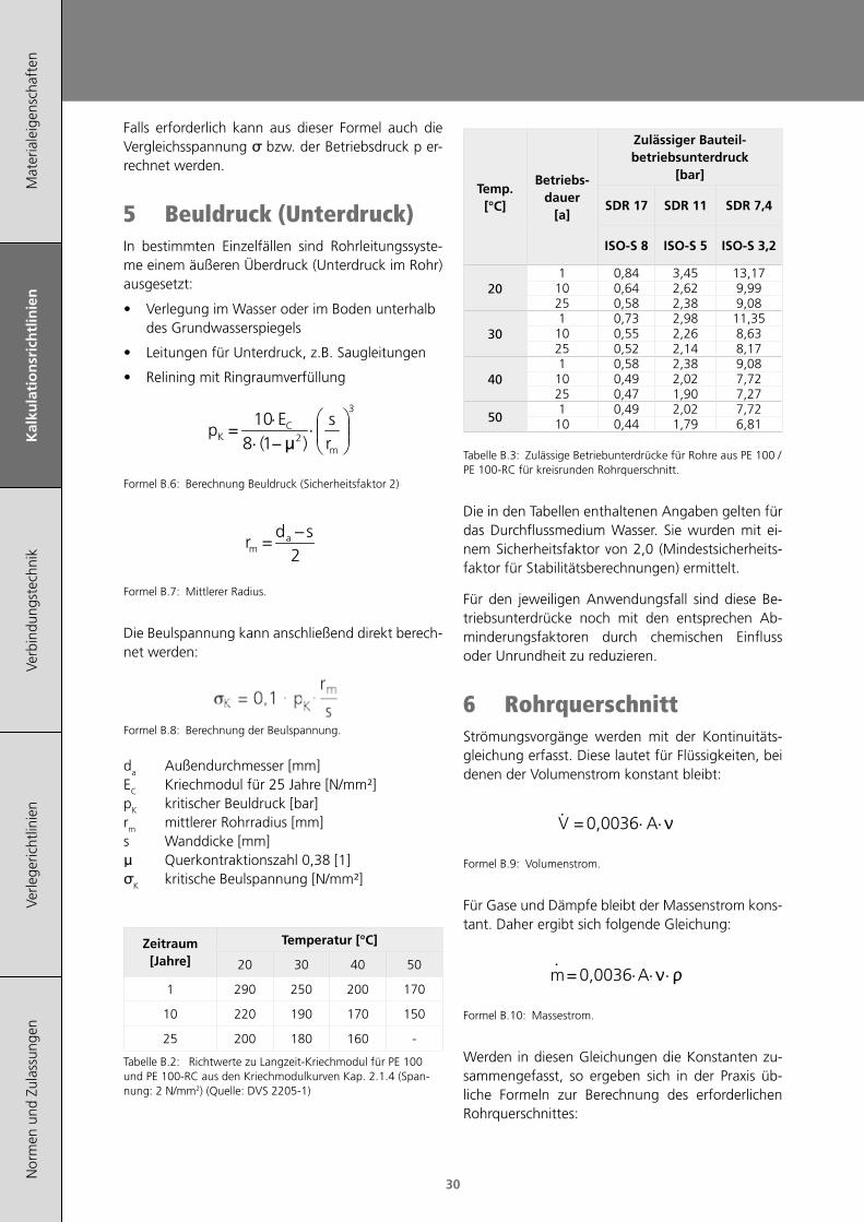
5 Beuldruck (Unterdruck)In bestimmten Einzelfällen sind Rohrleitungssyste-me einem äußeren Überdruck (Unterdruck im Rohr) ausgesetzt:
• Verlegung im Wasser oder im Boden unterhalb des Grundwasserspiegels
• Leitungen für Unterdruck, z.B. Saugleitungen
• Relining mit Ringraumverfüllung
⋅
⋅⋅
( )
3
21810
−=
m
CK r
sEp
µ
Formel B.6: Berechnung Beuldruck (Sicherheitsfaktor 2)
2sd
r am
−=
Formel B.7: Mittlerer Radius.
Die Beulspannung kann anschließend direkt berech-net werden:
Formel B.8: Berechnung der Beulspannung.
da Außendurchmesser [mm]EC Kriechmodul für 25 Jahre [N/mm²]pK kritischer Beuldruck [bar]rm mittlerer Rohrradius [mm]s Wanddicke [mm]μ Querkontraktionszahl 0,38 [1]σK kritische Beulspannung [N/mm²]
Zeitraum [Jahre]
Temperatur [°C]
20 30 40 50
1 290 250 200 170
10 220 190 170 150
25 200 180 160 -
Tabelle B.2: Richtwerte zu Langzeit-Kriechmodul für PE 100 und PE 100-RC aus den Kriechmodulkurven Kap. 2.1.4 (Span-nung: 2 N/mm2) (Quelle: DVS 2205-1)
Temp.[°C]
Betriebs-dauer
[a]
Zulässiger Bauteil-betriebsunterdruck
[bar]
SDR 17 SDR 11 SDR 7,4
ISO-S 8 ISO-S 5 ISO-S 3,2
201 0,84 3,45 13,1710 0,64 2,62 9,9925 0,58 2,38 9,08
301 0,73 2,98 11,35
10 0,55 2,26 8,6325 0,52 2,14 8,17
401 0,58 2,38 9,08
10 0,49 2,02 7,7225 0,47 1,90 7,27
501 0,49 2,02 7,72
10 0,44 1,79 6,81
Tabelle B.3: Zulässige Betriebunterdrücke für Rohre aus PE 100 / PE 100-RC für kreisrunden Rohrquerschnitt.
Die in den Tabellen enthaltenen Angaben gelten für das Durchflussmedium Wasser. Sie wurden mit ei-nem Sicherheitsfaktor von 2,0 (Mindestsicherheits-faktor für Stabilitätsberechnungen) ermittelt.
Für den jeweiligen Anwendungsfall sind diese Be-triebsunterdrücke noch mit den entsprechen Ab-minderungsfaktoren durch chemischen Einfluss oder Unrundheit zu reduzieren.
6 RohrquerschnittStrömungsvorgänge werden mit der Kontinuitäts-gleichung erfasst. Diese lautet für Flüssigkeiten, bei denen der Volumenstrom konstant bleibt:
⋅⋅⋅= AV 0,0036 ν
Formel B.9: Volumenstrom.
Für Gase und Dämpfe bleibt der Massenstrom kons-tant. Daher ergibt sich folgende Gleichung:
⋅⋅⋅⋅
= Am 0,0036 ρν
Formel B.10: Massestrom.
Werden in diesen Gleichungen die Konstanten zu-sammengefasst, so ergeben sich in der Praxis üb-liche Formeln zur Berechnung des erforderlichen Rohrquerschnittes:
Kalkulationsrichtlinien
Mat
eria
leig
ensc
haft
enK
alku
lati
on
sric
htl
inie
nVe
rbin
dung
stec
hnik
Verle
geric
htlin
ien
Nor
men
und
Zul
assu
ngen
31
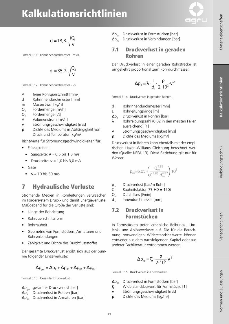
⋅ 118,8Q
di = ν
Formel B.11: Rohrinnendurchmesser - m³/h.
⋅ 235,7Q
di = ν
Formel B.12: Rohrinnendurchmesser - l/s.
A freier Rohrquerschnitt [mm²]di Rohrinnendurchmesser [mm]m Massestrom [kg/h]Q1 Fördermenge [m³/h]Q2 Fördermenge [l/s]V Volumenstrom [m³/h]ν Strömungsgeschwindigkeit [m/s]ρ Dichte des Mediums in Abhängigkeit von
Druck und Temperatur [kg/m³]
Richtwerte für Strömungsgeschwindigkeiten für:
• Flüssigkeiten:
• Saugseite: ν ≈ 0,5 bis 1,0 m/s
• Druckseite: ν ≈ 1,0 bis 3,0 m/s
• Gase
• ν ≈ 10 bis 30 m/s
7 Hydraulische VerlusteStrömende Medien in Rohrleitungen verursachen im Fördersystem Druck- und damit Energieverluste. Maßgebend für die Größe der Verluste sind:
• Länge der Rohrleitung
• Rohrquerschnittsform
• Rohrrauheit
• Geometrie von Formstücken, Armaturen und Rohrverbindungen
• Zähigkeit und Dichte des Durchflussstoffes
Der gesamte Druckverlust ergibt sich aus der Sum-me folgender Einzelverluste:
RVRARFRges ppppp +++= ΔΔΔΔΔ
Formel B.13: Gesamter Druckverlust.
Δpges gesamter Druckverlust [bar]ΔpR Druckverlust in Rohren [bar]ΔpRA Druckverlust in Armaturen [bar]
ΔpRF Druckverlust in Formstücken [bar]ΔpRV Druckverlust in Verbindungen [bar]
7.1 Druckverlust in geraden Rohren
Der Druckverlust in einer geraden Rohrstrecke ist umgekehrt proportional zum Rohrdurchmesser.
⋅⋅
⋅⋅ 22102
=i
R dL
p νρλΔ
Formel B.14: Druckverlust in geraden Rohren.
di Rohrinnendurchmesser [mm]L Rohrleitungslänge [m]ΔpR Druckverlust in Rohren [bar]λ Rohrreibungszahl (0,02 in den meisten Fällen
ausreichend) [1]ν Strömungsgeschwindigkeit [m/s]ρ Dichte des Mediums [kg/m³]
Druckverlust in Rohren kann ebenfalls mit der empi-rischen Hazen-Williams Gleichung berechnet wer-den (Quelle: NFPA 13). Diese Beziehung gilt nur für Wasser.
pm Druckverlust [bar/m Rohr]C Rauheitsfaktor (PE-HD = 150)Qm Durchfluss [l/min]dm Innendurchmesser [mm]
7.2 Druckverlust in Formstücken
In Formstücken treten erhebliche Reibungs-, Um-lenk- und Ablöseverluste auf. Die für die Berech-nung notwendigen Widerstandsbeiwerte können entweder aus dem nachfolgenden Kapitel oder aus anderer Fachliteratur entnommen werden.
⋅⋅
⋅ 25102
=RFp νρζΔ
Formel B.15: Druckverlust in Formstücken.
ΔpRF Druckverlust in Formstücken [bar]ζ Widerstandsbeiwert für Formstücke [1]ν Strömungsgeschwindigkeit [m/s]ρ Dichte des Mediums [kg/m³]
Mat
eria
leig
ensc
haft
enK
alku
lati
on
sric
htl
inie
nVe
rbin
dung
stec
hnik
Verle
geric
htlin
ien
Nor
men
und
Zul
assu
ngen
32
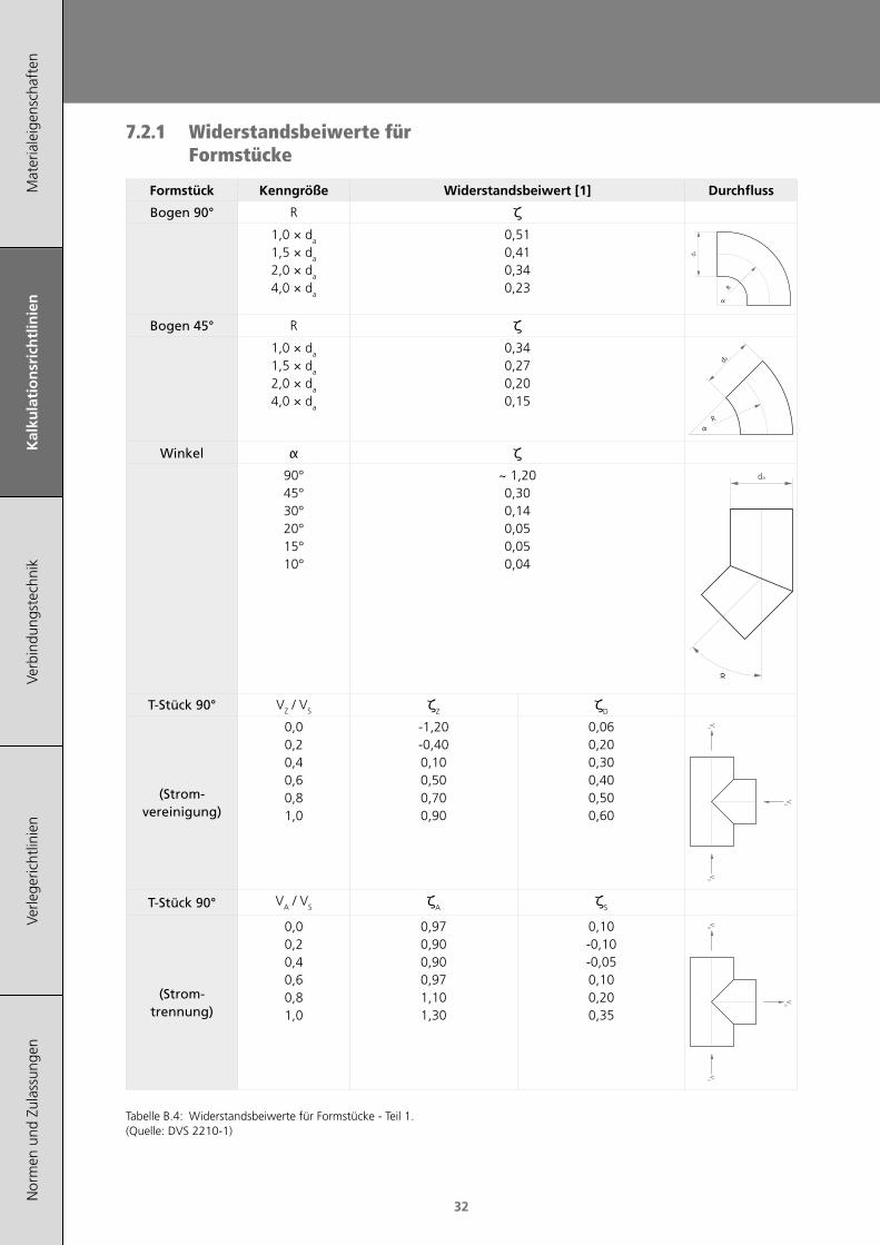
7.2.1 Widerstandsbeiwerte für Formstücke
Formstück Kenngröße Widerstandsbeiwert [1] Durchfluss
Bogen 90° R ζ1,0 × da
1,5 × da
2,0 × da
4,0 × da
0,510,410,340,23
α
da
R
Bogen 45° R ζ1,0 × da
1,5 × da
2,0 × da
4,0 × da
0,340,270,200,15
α
da
R
Winkel α ζ90°45°30°20°15°10°
~ 1,200,300,140,050,050,04
da
α
T‑Stück 90° VZ / VS ζZ ζD
(Strom‑vereinigung)
0,00,20,40,60,81,0
-1,20-0,400,100,500,700,90
0,060,200,300,400,500,60
VD
VS
VZ
T‑Stück 90° VA / VS ζA ζS
(Strom‑ trennung)
0,00,20,40,60,81,0
0,970,900,900,971,101,30
0,10-0,10-0,050,100,200,35
VD
VS
VA
Tabelle B.4: Widerstandsbeiwerte für Formstücke - Teil 1. (Quelle: DVS 2210-1)
Kalkulationsrichtlinien
Mat
eria
leig
ensc
haft
enK
alku
lati
on
sric
htl
inie
nVe
rbin
dung
stec
hnik
Verle
geric
htlin
ien
Nor
men
und
Zul
assu
ngen
33
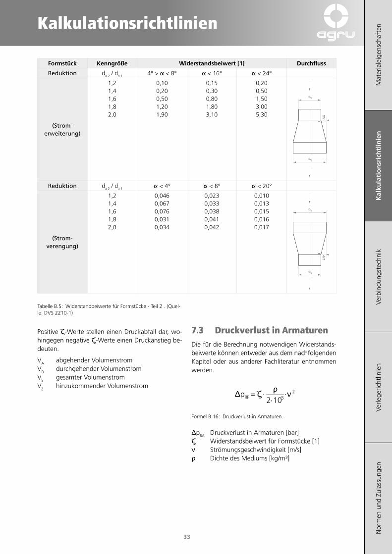
Formstück Kenngröße Widerstandsbeiwert [1] Durchfluss
Reduktion da 2 / da 1 4° > α < 8° α < 16° α < 24°
(Strom‑ erweiterung)
1,21,41,61,82,0
0,100,200,501,201,90
0,150,300,801,803,10
0,200,501,503,005,30
da1
α/2
da2
Reduktion da 2 / da 1 α < 4° α < 8° α < 20°
(Strom‑ verengung)
1,21,41,61,82,0
0,0460,0670,0760,0310,034
0,0230,0330,0380,0410,042
0,0100,0130,0150,0160,017
α/2
da1
da2
Tabelle B.5: Widerstandbeiwerte für Formstücke - Teil 2 . (Quel-le: DVS 2210-1)
Positive ζ-Werte stellen einen Druckabfall dar, wo-hingegen negative ζ-Werte einen Druckanstieg be-deuten.
VA abgehender VolumenstromVD durchgehender VolumenstromVS gesamter VolumenstromVZ hinzukommender Volumenstrom
7.3 Druckverlust in ArmaturenDie für die Berechnung notwendigen Widerstands-beiwerte können entweder aus dem nachfolgenden Kapitel oder aus anderer Fachliteratur entnommen werden.
⋅⋅
⋅ 25102
=RFp νρζΔ
Formel B.16: Druckverlust in Armaturen.
ΔpRA Druckverlust in Armaturen [bar]ζ Widerstandsbeiwert für Formstücke [1]ν Strömungsgeschwindigkeit [m/s]ρ Dichte des Mediums [kg/m³]
Mat
eria
leig
ensc
haft
enK
alku
lati
on
sric
htl
inie
nVe
rbin
dung
stec
hnik
Verle
geric
htlin
ien
Nor
men
und
Zul
assu
ngen
34
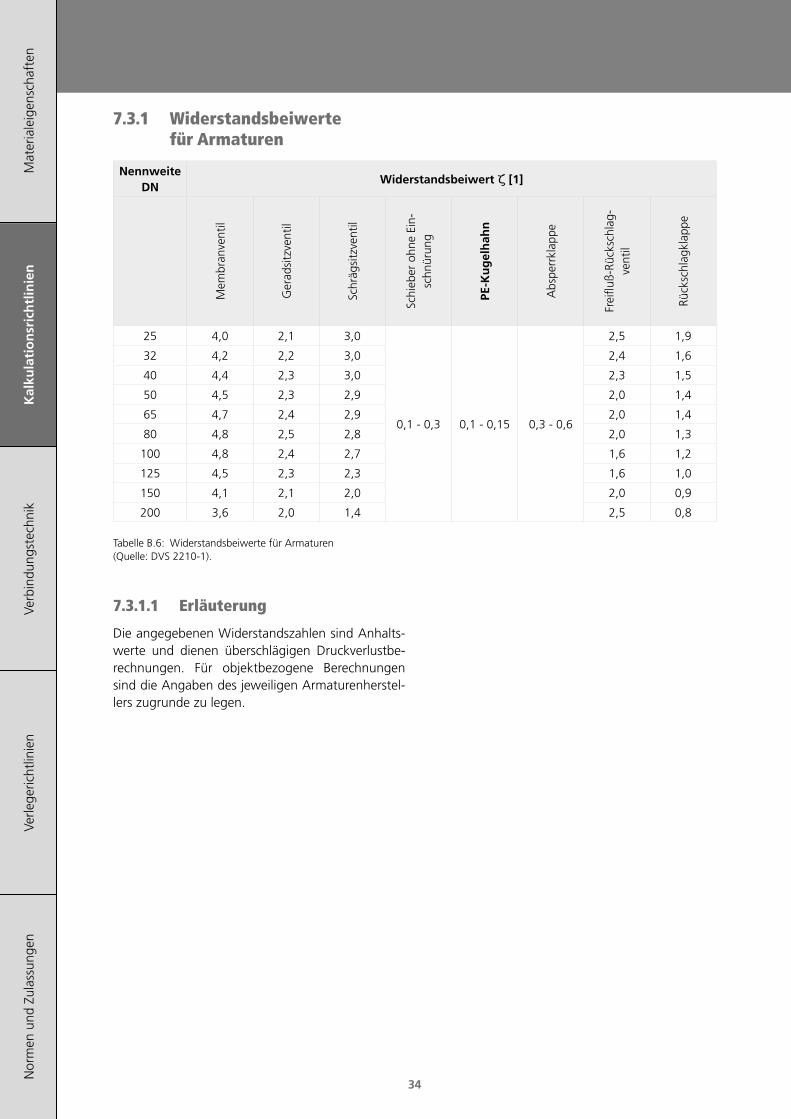
7.3.1 Widerstandsbeiwerte für Armaturen
Nennweite DN
Widerstandsbeiwert ζ [1]
Mem
bran
vent
il
Ger
adsi
tzve
ntil
Schr
ägsi
tzve
ntil
Schi
eber
ohn
e Ei
n-sc
hnür
ung
PE-K
ug
elh
ahn
Abs
perr
klap
pe
Frei
fluß-
Rück
schl
ag-
vent
il
Rück
schl
agkl
appe
25 4,0 2,1 3,0
0,1 - 0,3 0,1 - 0,15 0,3 - 0,6
2,5 1,9
32 4,2 2,2 3,0 2,4 1,6
40 4,4 2,3 3,0 2,3 1,5
50 4,5 2,3 2,9 2,0 1,4
65 4,7 2,4 2,9 2,0 1,4
80 4,8 2,5 2,8 2,0 1,3
100 4,8 2,4 2,7 1,6 1,2
125 4,5 2,3 2,3 1,6 1,0
150 4,1 2,1 2,0 2,0 0,9
200 3,6 2,0 1,4 2,5 0,8
Tabelle B.6: Widerstandsbeiwerte für Armaturen (Quelle: DVS 2210-1).
7.3.1.1 Erläuterung
Die angegebenen Widerstandszahlen sind Anhalts-werte und dienen überschlägigen Druckverlustbe-rechnungen. Für objektbezogene Berechnungen sind die Angaben des jeweiligen Armaturenherstel-lers zugrunde zu legen.

Kalkulationsrichtlinien
Mat
eria
leig
ensc
haft
enK
alku
lati
on
sric
htl
inie
nVe
rbin
dung
stec
hnik
Verle
geric
htlin
ien
Nor
men
und
Zul
assu
ngen
35
7.4 Kriterien für die Armaturenauswahl
Auswahl-kriterium
BewertungM
embr
anve
ntil,
Ge-
rads
itzve
ntil,
Sch
räg-
sitz
vent
il
Schi
eber
ohn
e Ei
n-sc
hnür
ung
PE-K
ug
elh
ahn
(an
a-lo
g E
N 1
2201
/E
N 1
555)
Abs
perr
klap
pe
Frei
fluß-
Rück
schl
ag-
vent
il
Rück
schl
agkl
appe
Strömungs‑widerstand
groß gering gering mäßig groß mäßig
Öffnungs‑ und Schließ‑
zeitenmittel lang kurz kurz kurz kurz
Betätigungs‑moment
gering geringmäßig (ohne Getriebe)
gering (mit Getriebe)mäßig
Verschleiß mäßig gering gering mäßig mäßig mäßig
Durchflussre‑gelung
geeignetwenig
geeignetwenig
geeignetwenig
geeignet- -
Baulänge nach Reihe F
mittel großdirekt in die Leitung
eingeschweißt
groß mittel groß
Baulänge nach Reihe K
- - gering - gering
Tabelle B.7: Kriterien für die Armaturenauswahl.
Reihe F Flanschausführung (DIN 3202-1)Reihe K Zwischenflanschausführung (DIN 3202-3)
Quelle: DVS 2210 Teil 1, Tabelle 11.
Mat
eria
leig
ensc
haft
enK
alku
lati
on
sric
htl
inie
nVe
rbin
dung
stec
hnik
Verle
geric
htlin
ien
Nor
men
und
Zul
assu
ngen
36
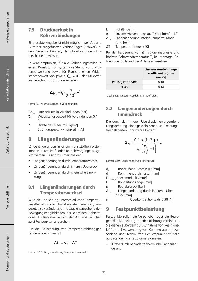
7.5 Druckverlust in Rohrverbindungen
Eine exakte Angabe ist nicht möglich, weil Art und Güte der ausgeführten Verbindungen (Schweißun-gen, Verschraubungen, Flanschverbindungen) Un-terschiede aufweisen.
Es wird empfohlen, für alle Verbindungsstellen in einem Kunststoffrohrsystem wie Stumpf- und Muf-fenschweißung sowie für Flansche einen Wider-standsbeiwert von jeweils ζRV = 0,1 der Druckver-lustberechnung zugrunde zu legen.
⋅⋅
⋅ 25102
pRV =ρζΔ ν
Formel B.17: Druckverlust in Verbindungen.
ΔpRV Druckverlust in Verbindungen [bar]ζ Widerstandsbeiwert für Verbindungen 0,1
[1]ρ Dichte des Mediums [kg/m³]ν Strömungsgeschwindigkeit [m/s]
8 LängenänderungenLängenänderungen in einem Kunststoffrohrsystem können durch Prüf- oder Betriebsvorgänge ausge-löst werden. Es sind zu unterscheiden:
• Längenänderungen durch Temperaturwechsel
• Längenänderungen durch inneren Überdruck
• Längenänderungen durch chemische Einwir-kung
8.1 Längenänderungen durch Temperaturwechsel
Wird die Rohrleitung unterschiedlichen Temperatu-ren (Betriebs- oder Umgebungstemperaturen) aus-gesetzt, so verändert sie ihre Lage entsprechend den Bewegungsmöglichkeiten der einzelnen Rohrstre-cken. Als Rohrstrecke wird der Abstand zwischen zwei Festpunkten angesehen.
Für die Berechnung von temperaturabhängigen Längenänderungen gilt:
⋅⋅ TLLT = ΔΔ α
Formel B.18: Längenänderung Temperaturwechsel.
L Rohrlänge [m]α linearer Ausdehnungskoeffizient [mm/(m·K)]ΔLT Längenänderung infolge Temperaturände-
rung [mm]ΔT Temperaturdifferenz [K]
Bei der Festlegung von ΔT ist die niedrigste und höchste Rohrwandtemperatur TR bei Montage, Be-trieb oder Stillstand der Anlage anzusetzen.
Linearer Ausdehnungs-koeffizient α [mm/
(m×K)]
PE 100, PE 100‑RC 0,18
PE‑Xa 0,14
Tabelle B.8: Linearer Ausdehnungskoeffizient.
8.2 Längenänderungen durch Innendruck
Die durch den inneren Überdruck hervorgerufene Längsdehnung einer geschlossenen und reibungs-frei gelagerten Rohrstrecke beträgt:
⋅
⋅⋅⋅⋅
( )L
dd
E
pL
i
aC
P
−
−=
1
210,1
2
2Δ μ
Formel B.19: Längenänderung Innendruck.
da Rohraußendurchmesser [mm]di Rohrinnendurchmesser [mm]EC_100minKriechmodul [N/mm²]L Rohrleitungslänge [mm]p Betriebsdruck [bar]ΔLP Längenänderung durch inneren Über-
druck [mm]μ Querkontraktionszahl 0,38 [1]
9 FestpunktbelastungFestpunkte sollen ein Verschieben oder ein Bewe-gen der Rohrleitung in jeder Richtung verhindern. Sie dienen außerdem zur Aufnahme von Reaktions-kräften bei Verwendung von Kompensatoren bzw. Schiebe- und Steckmuffen. Der Festpunkt ist für alle auftretenden Kräfte zu dimensionieren:
• Kräfte durch behinderte thermische Längenän-derung
Kalkulationsrichtlinien
Mat
eria
leig
ensc
haft
enK
alku
lati
on
sric
htl
inie
nVe
rbin
dung
stec
hnik
Verle
geric
htlin
ien
Nor
men
und
Zul
assu
ngen
37
• Gewicht bei senkrechten Rohrleitungen
• Spezifisches Gewicht des Durchflussmediums
• Betriebsdruck
• Eigenwiderstand der Dehnungsausgleicher
Frei wählbare Festpunkte sind so zu legen, dass Rich-tungsänderungen im Leitungsverlauf zur Aufnahme der Längenänderung ausgenutzt werden können.
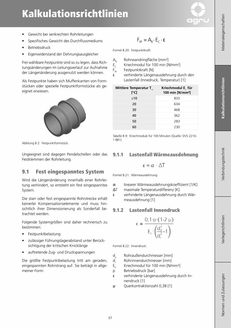
Als Festpunkte haben sich Muffenkanten von Form-stücken oder spezielle Festpunktformstücke als ge-eignet erwiesen.
Abbilung B.2: Festpunktformstück.
Ungeeignet sind dagegen Pendelschellen oder das Festklemmen der Rohrleitung.
9.1 Fest eingespanntes SystemWird die Längenänderung innerhalb einer Rohrlei-tung verhindert, so entsteht ein fest eingespanntes System.
Die starr oder fest eingespannte Rohrstrecke erhält keinerlei Kompensationselemente und muss hin-sichtlich ihrer Dimensionierung als Sonderfall be-trachtet werden.
Folgende Systemgrößen sind daher rechnerisch zu bestimmen:
• Festpunktbelastung
• zulässiger Führungslagerabstand unter Berück-sichtigung der kritischen Knicklänge
• auftretende Zug- und Druckspannungen
Die größte Festpunktbelastung tritt am geraden, eingespannten Rohrstrang auf. Sie beträgt in allge-meiner Form:
⋅⋅= CRFP EAF ε
Formel B.20: Festpunktkraft.
AR Rohrwandringfläche [mm²]EC Kriechmodul für 100 min [N/mm²]FFP Festpunktkraft [N]ε verhinderte Längenausdehnung durch den
Lastenfall (Innedruck, Temperatur) [1]
Mittlere Temperatur Tm [°C]
Kriechmodul EC für 100 min [N/mm²]
≤10 833
20 634
30 468
40 362
50 283
60 230
Tabelle B.9: Kriechmodule für 100 Minuten (Quelle: DVS 2210-1 BB1).
9.1.1 Lastenfall Wärmeausdehnung
Formel B.21: Wärmeausdehnung.
α linearer Wärmeausdehnungskoeffizient [1/K]ΔT maximale Temperaturdifferenz [K]ε verhinderte Längenausdehnung durch Wär-
meausdehnung [1]
9.1.2 Lastenfall Innendruck
Formel B.22: Innendruck.
da Rohraußendurchmesser [mm]di Rohrinnendurchmesser [mm]EC Kriechmodul für 100 min [N/mm²]p Betriebsdruck [bar]ε verhinderte Längenausdehnung durch In-
nendruck [1]μ Querkontraktionzahl 0,38 [1]
Mat
eria
leig
ensc
haft
enK
alku
lati
on
sric
htl
inie
nVe
rbin
dung
stec
hnik
Verle
geric
htlin
ien
Nor
men
und
Zul
assu
ngen
38
9.1.3 Lastenfall Quellung
Achtung: ein fest eingespanntes System is bei einem Dehnungslastfall bzgl. Quellung im Allgemeinenen nicht empfehlenswert, da durch die Quellung auch eine Schwächung des Materials auftritt.
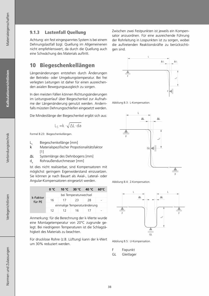
10 BiegeschenkellängenLängenänderungen entstehen durch Änderungen der Betriebs- oder Umgebungstemperatur. Bei frei verlegten Leitungen ist daher für einen ausreichen-den axialen Bewegungsausgleich zu sorgen.
In den meisten Fällen können Richtungsänderungen im Leitungsverlauf über Biegeschenkel zur Aufnah-me der Längenänderung genutzt werden. Andern-falls müssten Dehnungsschleifen eingesetzt werden.
Die Mindestlänge der Biegeschenkel ergibt sich aus:
Formel B.23: Biegeschenkellängen.
LS Biegeschenkellänge [mm]k Materialspezifischer Propotionalitätsfaktor
[1]ΔL Systemlänge des Dehnbogens [mm]da Rohraußendurchmesser [mm]
Ist dies nicht realisierbar, sind Kompensatoren mit möglichst geringem Eigenwiderstand einzusetzen. Sie können je nach Bauart als Axial-, Lateral- oder Angular-Kompensatoren eingesetzt werden.
k‑Faktorfür PE
0 °C 10 °C 30 °C 40 °C 60°C
bei Temperaturwechsel
16 17 23 28 -
einmalige Temperaturänderung
12 12 16 17 -
Anmerkung: für die Berechnung der k-Werte wurde eine Montagetemperatur von 20°C zugrunde ge-legt. Bei niedrigeren Temperaturen ist die Schlagzä-higkeit des Materials zu beachten.
Für drucklose Rohre (z.B. Lüftung) kann der k-Wert um 30% reduziert werden.
Zwischen zwei Festpunkten ist jeweils ein Kompen-sator anzuordnen. Für eine ausreichende Führung der Rohrleitung in Lospunkten ist zu sorgen, wobei die auftretenden Reaktionskräfte zu berücksichti-gen sind.
F
F
L
Δ L Δ L
L S
Abbilung B.3: L-Kompensation.
F
GL
F
L
ΔL ΔL
L S
Abbilung B.4: Z-Kompensation.
F
GL
F
L L
ΔL ΔL
L S
Abbilung B.5: U-Kompensation.
F FixpunktGL Gleitlager
Kalkulationsrichtlinien
Mat
eria
leig
ensc
haft
enK
alku
lati
on
sric
htl
inie
nVe
rbin
dung
stec
hnik
Verle
geric
htlin
ien
Nor
men
und
Zul
assu
ngen
39
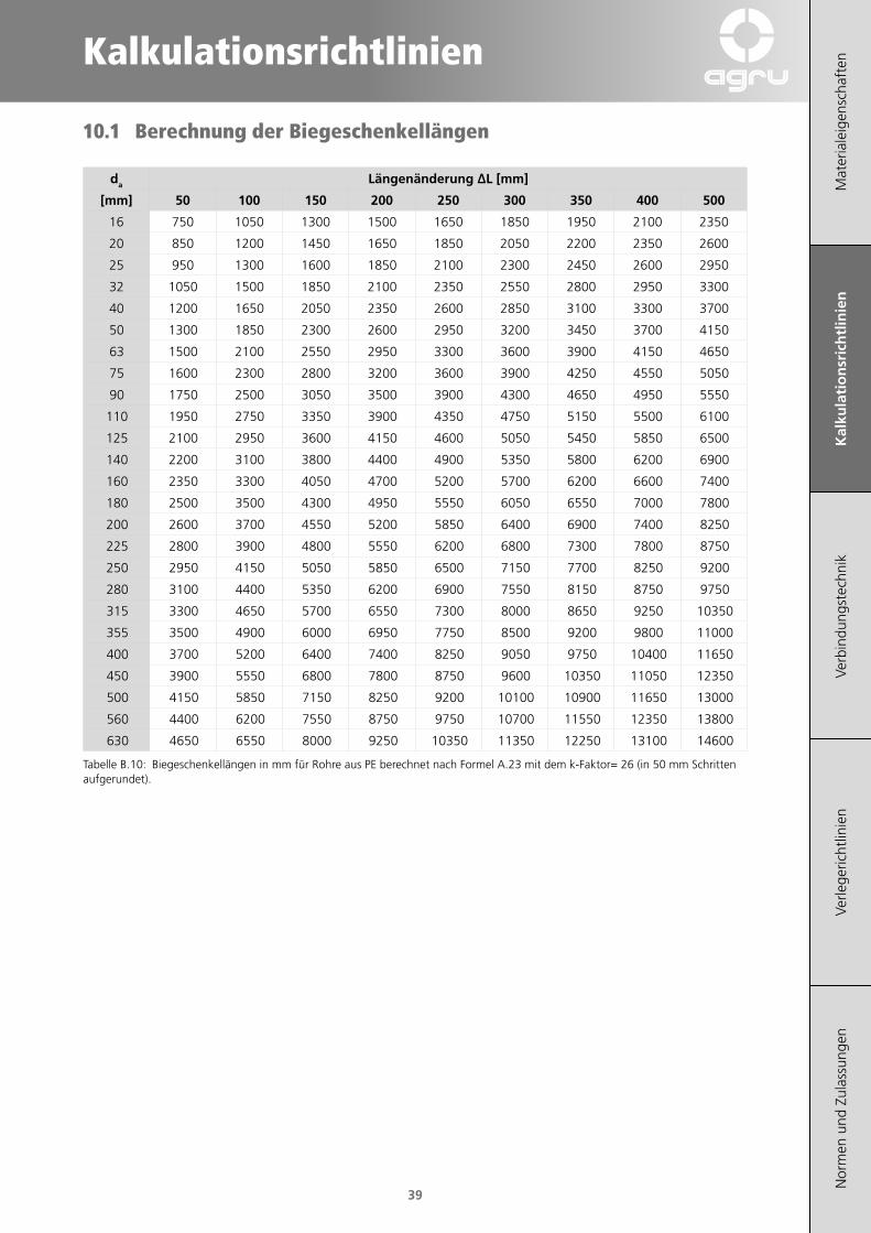
10.1 Berechnung der Biegeschenkellängen
da Längenänderung ∆L [mm]
[mm] 50 100 150 200 250 300 350 400 500
16 750 1050 1300 1500 1650 1850 1950 2100 2350
20 850 1200 1450 1650 1850 2050 2200 2350 2600
25 950 1300 1600 1850 2100 2300 2450 2600 2950
32 1050 1500 1850 2100 2350 2550 2800 2950 3300
40 1200 1650 2050 2350 2600 2850 3100 3300 3700
50 1300 1850 2300 2600 2950 3200 3450 3700 4150
63 1500 2100 2550 2950 3300 3600 3900 4150 4650
75 1600 2300 2800 3200 3600 3900 4250 4550 5050
90 1750 2500 3050 3500 3900 4300 4650 4950 5550
110 1950 2750 3350 3900 4350 4750 5150 5500 6100
125 2100 2950 3600 4150 4600 5050 5450 5850 6500
140 2200 3100 3800 4400 4900 5350 5800 6200 6900
160 2350 3300 4050 4700 5200 5700 6200 6600 7400
180 2500 3500 4300 4950 5550 6050 6550 7000 7800
200 2600 3700 4550 5200 5850 6400 6900 7400 8250
225 2800 3900 4800 5550 6200 6800 7300 7800 8750
250 2950 4150 5050 5850 6500 7150 7700 8250 9200
280 3100 4400 5350 6200 6900 7550 8150 8750 9750
315 3300 4650 5700 6550 7300 8000 8650 9250 10350
355 3500 4900 6000 6950 7750 8500 9200 9800 11000
400 3700 5200 6400 7400 8250 9050 9750 10400 11650
450 3900 5550 6800 7800 8750 9600 10350 11050 12350
500 4150 5850 7150 8250 9200 10100 10900 11650 13000
560 4400 6200 7550 8750 9750 10700 11550 12350 13800
630 4650 6550 8000 9250 10350 11350 12250 13100 14600
Tabelle B.10: Biegeschenkellängen in mm für Rohre aus PE berechnet nach Formel A.23 mit dem k-Faktor= 26 (in 50 mm Schritten aufgerundet).

Mat
eria
leig
ensc
haft
enK
alku
lati
on
sric
htl
inie
nVe
rbin
dung
stec
hnik
Verle
geric
htlin
ien
Nor
men
und
Zul
assu
ngen
40
11 RohrstützweitenDie Unterstützungsabstände von thermoplastischen Kunststoffrohrleitungen sind unter Beachtung der zulässigen Biegespannung und einer begrenzten Durchbiegung des Rohrstranges zu bestimmen. Als Richtwert für die zulässige Durchbiegung kann LA/500 angenommen werden.
Unter Berücksichtigung der vorgenannten Durch-biegung einer Rohrstrecke zwischen den Auflage-punkten ergibt sich ein zulässiger Unterstützungs-abstand der Rohrleitung.
⋅⋅ 3
qJE
fL RCLAA =
Formel B.24: Rohrstützweite bei freiverlegeten Leitungen.
Der Faktor fLA ist in Abhängigkeit zum Rohraußen-durchmesser da festzulegen. Dabei gilt die folgende Beziehung:
min ← da → max
0,92 ← fLA → 0,80
Übliche Stützweiten von thermoplastischen Rohrlei-tungen können dem folgenden Kapitel entnommen werden.
Bei fest eingespannten Rohrleitungssystemen (Kap. Festpunktbelastung) muss zusätzlich die kritische Länge gegen Knickung berechnet werden. Diese kritische Knicklänge wird dann mit der zulässigen Stützweite verglichen, wobei der kleinere Wert dann zu beachten ist.
EC Kriechmodul für 25 Jahre [N/mm²] (Abmin-derungsfaktor ≥2 berücksichtigen, s. 2.1.4)
fLA Faktor für die Durchbiegung (0,80 - 0,92)[1]JR Rohr-Trägheitsmoment [mm4]LA zulässige Unterstützungsabstand [mm]q Streckenlast (Rohr-, Füll- und Zusatzgewicht)
[N/mm]LKn,zul kritische Knicklänge [mm]W Rohr-Widerstandsmoment [mm³]da Rohraußendurchmesser [mm]ε verhinderte Längsdehnung [1]AR Rohrwandquerschnitt [mm²]
Bei Einsatztemperaturen über 45 °C ist die ermittel-te Stützweite LKn um mind. 20% zu reduzieren.
Nachfolgende Tabelle dient zur überschlägigen Um-rechnung auf andere Transportmedien und SDR-Klassen. Ausgangsgrößen sind:
• PE-Rohr
• SDR 11
• Transportmedium Wasser
Medien- und Wanddickenfaktor [1]
SDR f Wand
f medium
Wasser Gas
17 0,91 1 1,47
11 1 1 1,30
7,4 1,07 1 1,21

Kalkulationsrichtlinien
Mat
eria
leig
ensc
haft
enK
alku
lati
on
sric
htl
inie
nVe
rbin
dung
stec
hnik
Verle
geric
htlin
ien
Nor
men
und
Zul
assu
ngen
41
11.1 Richtwerte zu Stützweiten für frei verlegte Rohre und Medium Wasser (PE 100 & PE 100-RC)
11.1.1 SDR 11
da [mm] Rohrstützweiten LA [mm] (frei verlegt, für Wasser, PE100 / PE100-RC)
20 °C 30 °C 40 °C 50 °C 60 °C
20 600 600 550 450 400
25 700 650 600 600 550
32 800 800 700 700 600
40 950 900 800 800 700
50 1150 1100 950 900 800
63 1300 1250 1150 1100 950
75 1450 1400 1300 1200 1100
90 1650 1550 1450 1350 1250
110 1800 1750 1650 1550 1400
125 1900 1850 1750 1700 1500
140 2050 2000 1900 1800 1650
160 2250 2100 2000 1900 1750
180 2350 2250 2100 2000 1900
200 2500 2400 2300 2200 2050
225 2650 2550 2450 2350 2250
250 2850 2750 2600 2500 2300
280 3000 2900 2800 2600 2400
315 3150 3050 2950 2800 2550
355 3400 3300 3150 3000 2800
400 3600 3450 3350 3150 2950
450 4000 3850 3600 3550 3350
500 4250 4100 3850 3800 3600
560 4550 4400 4150 4100 3850
630 4900 4700 4500 4400 4150
710 5250 5050 4850 4750 4500
800 5600 5450 5250 5100 4850
900 6000 5800 5650 5450 5200
1000 6400 6200 6050 5850 5600
1200 7150 6900 6850 6550 6250
1400 7800 7550 7550 7150 6900
Tabelle B.11: Richtwerte für Rohrstützweiten (Dim 20-400 mm aus DVS 2210-1, Dim 450-1400 berechnet mit fLA=0,86), aufgerundet in 50 mm Schritten

Mat
eria
leig
ensc
haft
enK
alku
lati
on
sric
htl
inie
nVe
rbin
dung
stec
hnik
Verle
geric
htlin
ien
Nor
men
und
Zul
assu
ngen
42
12 RingsteifigkeitDie Ringsteifigkeit beschreibt die Scheiteltragfähig-keit und hat die Abkürzung SN. Diese Abkürzung steht für Stiffness-Number und wird in Klassen ein-geteilt. Die Ringsteifigkeit wird in kN/m² angege-ben und wird mittels Laboruntersuchung ermittelt. Das Rohr wird 21 Tage nach der Produktion ca. 3% deformiert. Die dafür notwendige Flächenlast wird auf die nächste kleinere ganze Zahl abgerundet. Das bedeutet das ein Rohr mit der Ringsteifigkeitsklasse SN 2 eine Flächenlast von min. 2 kN/m² bei einer Verformung < 3% stand hält.
Der Einfluss der Ringsteifigkeit bei biegeweichen Kunststoffrohrsystemen wird überschätzt. Das Rohr muss zum Zeitpunkt des Einbaus eine genügende Ringsteifigkeit besitzen, um die Last aus der Ver-dichtung aufnehmen zu können. Bei einer guten Verdichtungsarbeit im Bereich der Leitungszone trägt der Boden die auftretenden Lasten, das Rohr selbst entzieht sich den Lasten durch Verformung (in der Regel 2 % bis 3 %) und liegt nach einem Zeit-raum von ca. 2 Jahren (Relaxation) lastfrei im Boden. Eine Ringsteifigkeit von 8 kN/m² ist als optimal und ausreichend zu betrachten.
Die Ringsteifigkeit wird nach EN 12201-2 in folgen-de Klassen eingeteilt:
SDR ISO S SN [kN/m2]
41 20 1,3
33 16 2,5
26 12,5 5,3
21 10 10,4
17 8 20,3
13,6 6,3 41,7
11 5 83,3
9 4 162,8
7,4 3,2 317,9
6 2,5 668,7
Tabelle B.12: Anfängliche Ringsteifigkeit von Rohren (kalkuliert mit E-Modul E = 1000 MPa)
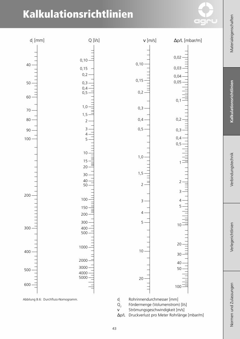
13 Durchfluss (Nomogramm)Zur groben Ermittlung von Strömungsgeschwindig-keit, Druckverlust und Fördermenge dient das nach-folgende Durchfluss-Nomogramm.
Bei mittlerer Strömungsgeschwindigkeit werden pro T-Stück, Reduktion und Winkel 90° bis zu 20 m, pro Bogen (r = d) ca. 10 m und pro Bogen (r = 1,5 × d) 5 m Rohrlänge zugeschlagen.
Kalkulationsrichtlinien
Mat
eria
leig
ensc
haft
enK
alku
lati
on
sric
htl
inie
nVe
rbin
dung
stec
hnik
Verle
geric
htlin
ien
Nor
men
und
Zul
assu
ngen
43
40
50
60
70
80
90
100
200
300
400
500
600
0,10
0,15
0,2
0,30,40,5
1,0
1,5
2
345
10
15
20
30
4050
100
150
200
300
400500
1000
2000
300040005000
0,10
0,15
0,2
0,3
0,4
0,5
1,0
1,5
2
3
4
5
10
20
0,02
0,03
0,04
0,05
0,1
0,2
0,3
0,4
0,5
1
2
3
4
5
10
20
30
40
50
100
di [mm] Q [l/s] Δp/L [mbar/m]ν [m/s]
Abbilung B.6: Durchfluss-Nomogramm. di Rohrinnendurchmesser [mm]Q2 Fördermenge (Volumenstrom) [l/s]ν Strömungsgeschwindigkeit [m/s]Δp/L Druckverlust pro Meter Rohrlänge [mbar/m]

Mat
eria
leig
ensc
haft
enK
alku
lati
on
sric
htl
inie
nVe
rbin
dung
stec
hnik
Verle
geric
htlin
ien
Nor
men
und
Zul
assu
ngen
44
14 Berechnungshilfen
14.1 Umrechnungstabellen
Pa = N/m² MPa bar mm WS
1 Pa = N/m² 1 10-6 10-5 10-2
1 MPa = 1 N/mm² 106 1 10 1,02 · 105
1 bar 105 0,1 1 1,02 · 104
1 mm WS 9,81 9,81 · 10-6 9,81 · 10-5 1
Tabelle B.13: Umrechnung Druck
mm cm dm m km
1 mm 1 10-1 10-2 10-3 10-6
1 cm 10 1 10-1 10-2 10-5
1 dm 102 10 1 10-1 10-4
1 m 103 102 10 1 10-3
1 km 106 105 104 103 1
Tabelle B.14: Umrechnung Länge
mm² cm² dm² m²
1 mm² 1 10-2 10-4 10-6
1 cm² 102 1 10-2 10-4
1 dm² 104 102 1 10-2
1 m² 106 104 102 1
Tabelle B.15: Umrechnung Flächen
t kg g mg
1 t 1 103 106 109
1 kg 10-3 1 103 106
1 g 10-6 10-3 1 103
1 mg 10-9 10-6 10-3 1
Tabelle B.16: Umrechnung Masse
mm3 cm3 dm3 m3
1 mm3 1 10-3 10-6 10-9
1 cm3 103 1 10-3 10-6
1 dm3 = 1l Wasser 106 103 1 10-3
1 m3 109 106 103 1
Tabelle B.17: Umrechnung Volumen

Kalkulationsrichtlinien
Mat
eria
leig
ensc
haft
enK
alku
lati
on
sric
htl
inie
nVe
rbin
dung
stec
hnik
Verle
geric
htlin
ien
Nor
men
und
Zul
assu
ngen
45
1
Meter
[m]
3,28
feet
[ft]
39,37
inch
[in]
1
Liter
[l]
0,264
Gallons
[Ga]
0,035
cubic feet
[ft3]
1
Kilogramm
[kg]
2,204
Pounds
[lbs]
9,81
Newton
[N]
1
bar
[bar]
14,505
Pound/sq. inch
[psi]
100
Kilopascal
[kPa]
Tabelle B.19: Umrechnung SI-Maßeinheiten
14.2 Formeln
14.2.1 Kreis
Fläche
Umfang
da [mm] DN Zoll
10 6 -
12 8 -
16 10 -
20 15 1/2
25 20 3/4
32 25 1
40 32 11/4
50 40 11/2
63 50 2
75 65 21/2
90 80 3
110 100 4
125 100 41/2
140 125 5
160 150 6
180 150 7
200 200 8
225 200 9
250 250 10
280 250 11
315 300 12
355 350 14
400 400 16
450 500 18
500 500 20
560 600 22
630 600 25
710 700 28
800 800 32
900 900 36
1000 1000 40
1200 1200 48
Tabelle B.18: Zusammenhang zwischen Aussendurchmesser, Nennweite und Zoll
Mat
eria
leig
ensc
haft
enK
alku
lati
on
sric
htl
inie
nVe
rbin
dung
stec
hnik
Verle
geric
htlin
ien
Nor
men
und
Zul
assu
ngen
46
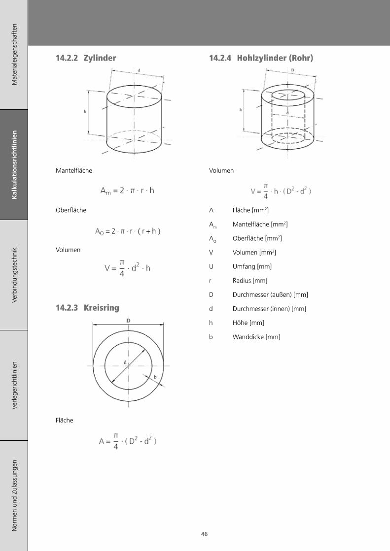
14.2.4 Hohlzylinder (Rohr)
Volumen
A Fläche [mm2]
Am Mantelfläche [mm2]
AO Oberfläche [mm2]
V Volumen [mm3]
U Umfang [mm]
r Radius [mm]
D Durchmesser (außen) [mm]
d Durchmesser (innen) [mm]
h Höhe [mm]
b Wanddicke [mm]
14.2.2 Zylinder
Mantelfläche
Oberfläche
Volumen
14.2.3 Kreisring
Fläche

Verbindungstechnik
Mat
eria
leig
ensc
haft
enK
alku
latio
nsric
htlin
ien
Ver
bin
du
ng
stec
hn
ikVe
rlege
richt
linie
nN
orm
en u
nd Z
ulas
sung
en
47
1 Allgemeine Anforderungen 49
2 Heizelement-Stumpfschweißen (HS) 51
3 Heizelement-Muffenschweißen 54
4 Heizwendelschweißen DIM 20-500mm monofilar 56
5 Heizwendelschweißen DIM 560-1400mm bifilar 60
6 Schellen 64
7 Druckprüfung 69

Mat
eria
leig
ensc
haft
enK
alku
latio
nsric
htlin
ien
Ver
bin
du
ng
stec
hn
ikVe
rlege
richt
linie
nN
orm
en u
nd Z
ulas
sung
en
48

Verbindungstechnik
Mat
eria
leig
ensc
haft
enK
alku
latio
nsric
htlin
ien
Ver
bin
du
ng
stec
hn
ikVe
rlege
richt
linie
nN
orm
en u
nd Z
ulas
sung
en
49
1 Allgemeine Anforderungen
(Gilt für alle Schweißverfahren)
Die Qualität von Schweißverbindungen ist abhängig von der Qualifikation der Schweißer, der Eignung der verwendeten Maschinen und Vorrichtungen sowie der Einhaltung der Schweißrichtlinien.(DVS 2207 Teil 1). Die Schweißnaht kann durch zerstö-rungsfreie und/oder zerstörende Verfahren geprüft werden.
Die Schweißarbeiten sind zu überwachen. Art und Umfang der Überwachung muss zwischen den Ver-tragspartnern vereinbart werden. Es wird empfoh-len die Verfahrensdaten in Schweißprotokollen oder auf Datenträgern zu dokumentieren.
Jeder Schweißer muss ausbildet sein und einen gültigen Qualifikationsnachweis führen. Das vor-gesehene Anwendungsgebiet kann für die Art der Qualifikation bestimmend sein. Im industriellen Rohrleitungsbau gilt DVS 2212 Teil 1. Für Rohre >225 mm Aussendurchmesser ist ein ergänzender Befähigungsnachweis zu erbringen.
Die zum Schweißen verwendeten Maschinen und Vorrichtungen müssen den Anforderungen von DVS 2208-1 entsprechen. Für das Schweißen von Kunst-stoffen in der Hausinstallation gelten auch die An-forderungen der Merkblätter DVS 1905 Teil 1 und 2.
1.1 Maßnahmen vor dem Schweißen.
Der Schweißbereich soll vor ungünstigen Witte-rungseinflüssen (z.B. Feuchtigkeitseinwirkung, ext-reme Temperaturen) geschützt werden.
Tabelle C.1: Vorbereitung des Schweissplatzes nach DVS
Schweissen ist grundsätzlich bei jeder Aussentempe-ratur möglich, wenn durch geeignete Maßnahmen (z.B. Vorwärmen, Schweisszelt, Beheizen) sicherge-stellt wird, dass eine zum Schweißen ausreichende Halbzeugtemperatur eingehalten werden kann und soweit der Schweißer nicht in der Handfertigkeit be-hindert wird. (s. Abb. D.1)
Die Verschweißbarkeit der zu verbindenden Komponenten muss durch die Herstellung von Probenähten unter den auf der Baustelle vorherrschenden Bedingungen nachgewiesen werden.
Falls das Halbzeug (Rohr oder Formteil) infolge der Sonneneinstrahlung ungleichmässig erwärmt wird, ist durch rechtzeitiges Abdecken im Bereich der Schweißstelle ein Temperaturausgleich zu schaffen. Eine Abkühlung während des Schweißvorganges durch Luftzug ist zu vermeiden. Beim Schweissen von Rohren sollen die Rohrenden zusätzlich ver-schlossen werden um den Kamineffekt zu vermei-den.
PE Rohre vom Ringbund sind unmittelbar nach dem Abrollen oval. Das zu schweissende Rohrende ist vor dem Schweissen zu richten, zum Beispiel durch vor-sichtiges Anwärmen mit Hilfe eines Warmluftgerä-tes und Verwendung einer geeigneten Spann- und/oder Runddrückvorrichtung.
Die Verbindungsflächen der zu schweissenden Teile dürfen nicht beschädigt und müssen frei von Verun-reinigung (z.B. Schmutz, Fett, Späne) sein.
Vor dem Schweißen müssen die zu verbindenden Teile mit einem, extra dafür vorgesehenen, Reiniger gereinigt werden (PE-Reiniger aus Isopropanol, Ace-ton oder Ethylalkohol gemäß DVGW VP 603).
Achtung: Verunreinigungen mit Silikonfetten kön-nen mit den meisten Reinigern nicht entfernt wer-den. In diesem Fall können Bremsenreiniger verwen-det werden. Die Tauglichkeit muss jedoch vorher mit dem Hersteller abgeklärt, und Probeschweißungen durchgeführt werden.
Bei allen Verfahren ist der Schweißbereich von Bie-gespannungen freizuhalten (z.B. sorgfältige Lage-rung, Rollenböcke), und eine einwandfreie axiale Ausrichtung ist sicherzustellen.

Mat
eria
leig
ensc
haft
enK
alku
latio
nsric
htlin
ien
Ver
bin
du
ng
stec
hn
ikVe
rlege
richt
linie
nN
orm
en u
nd Z
ulas
sung
en
50
Die AGRU-Schweißrichtlinien sind gültig für die Ver-schweißung von Rohren und Formstücken aus den in der Tabelle D.1 enthaltenen Thermoplasten.
Materialbezeichnung Schweißeignung
PE-80, PE-100, PE-100 RC
MFR(190/5)= 0,3 - 1,7 (g/10min)
0,2 - 1,3 (g/10min) für Sattelschweißungen
Tabelle C.2: Thermoplaste für die Verschweissung (Quelle: DVS 2207-1)
Verbindungsart
da
20 - 63 75 - 110 125 - 225 250 - 500 560 - 1400 1400 - 2500
Heizelement Stumpf- schweißung
Heizelement Muffen- schweißung
Heizwendel-schweißung
Flansch- verbindung
Verschraubung
Tabelle C.3: Zulässige längskraftschlüssige Verbindungen
1.2 Anforderung an die Schweißgeräte
Alle Schweißungen müssen mit Maschinen und Ge-räten durchgeführt werden, die den Anforderungen von DVS 2208 Teil1 entsprechen.
Die Maschinen müssen gewartet sein und die Heizelemente müssen mit einem dafür vorgesehe-nen Reinigungsmittel gereinigt werden.
1.3 Anwendungsgrenzen der Verbindungsarten
Sämtliche Verbindungen sind spannungsfrei aus-zuführen. Temperaturbedingte Spannungen sind durch geeignete Maßnahmen möglichst gering zu halten.
Die längskraftschlüssigen Verbindungen sind in fol-genden Dimensionen zulässig (Tabelle D.2):
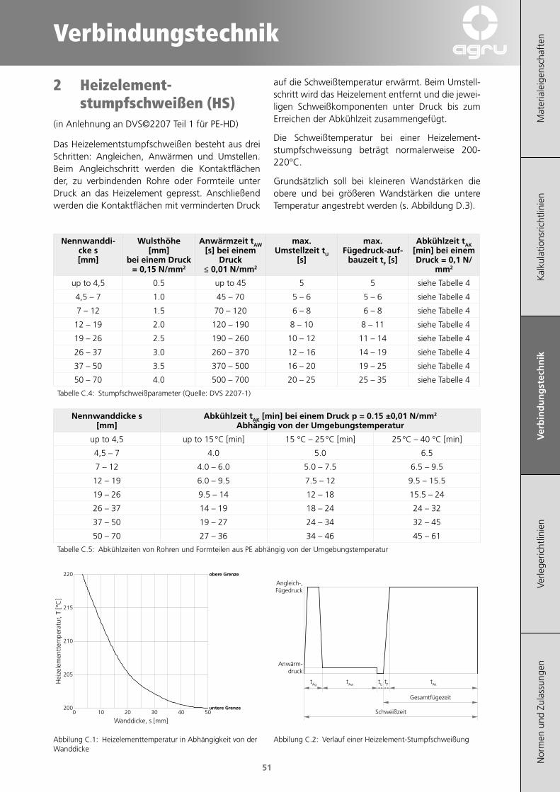
Verbindungstechnik
Mat
eria
leig
ensc
haft
enK
alku
latio
nsric
htlin
ien
Ver
bin
du
ng
stec
hn
ikVe
rlege
richt
linie
nN
orm
en u
nd Z
ulas
sung
en
51
2 Heizelement-stumpfschweißen (HS)
(in Anlehnung an DVS©2207 Teil 1 für PE-HD)
Das Heizelementstumpfschweißen besteht aus drei Schritten: Angleichen, Anwärmen und Umstellen. Beim Angleichschritt werden die Kontaktflächen der, zu verbindenden Rohre oder Formteile unter Druck an das Heizelement gepresst. Anschließend werden die Kontaktflächen mit verminderten Druck
200
205
210
215
220
0 10 20 30 40 50
Wanddicke, s [mm]
Hei
zele
men
ttem
pera
tur,
T [°
C]
untere Grenze
obere Grenze
Abbilung C.1: Heizelementtemperatur in Abhängigkeit von der Wanddicke
auf die Schweißtemperatur erwärmt. Beim Umstell-schritt wird das Heizelement entfernt und die jewei-ligen Schweißkomponenten unter Druck bis zum Erreichen der Abkühlzeit zusammengefügt.
Die Schweißtemperatur bei einer Heizelement-stumpfschweissung beträgt normalerweise 200-220°C.
Grundsätzlich soll bei kleineren Wandstärken die obere und bei größeren Wandstärken die untere Temperatur angestrebt werden (s. Abbildung D.3).
Nennwanddi-cke s [mm]
Wulsthöhe [mm]
bei einem Druck = 0,15 N/mm2
Anwärmzeit tAW [s] bei einem
Druck ≤ 0,01 N/mm2
max. Umstellzeit tU
[s]
max. Fügedruck-auf-
bauzeit tF [s]
Abkühlzeit tAK [min] bei einem Druck = 0,1 N/
mm2
up to 4,5 0.5 up to 45 5 5 siehe Tabelle 4
4,5 – 7 1.0 45 – 70 5 – 6 5 – 6 siehe Tabelle 4
7 – 12 1.5 70 – 120 6 – 8 6 – 8 siehe Tabelle 4
12 – 19 2.0 120 – 190 8 – 10 8 – 11 siehe Tabelle 4
19 – 26 2.5 190 – 260 10 – 12 11 – 14 siehe Tabelle 4
26 – 37 3.0 260 – 370 12 – 16 14 – 19 siehe Tabelle 4
37 – 50 3.5 370 – 500 16 – 20 19 – 25 siehe Tabelle 4
50 – 70 4.0 500 – 700 20 – 25 25 – 35 siehe Tabelle 4
Tabelle C.4: Stumpfschweißparameter (Quelle: DVS 2207-1)
Nennwanddicke s [mm]
Abkühlzeit tAK [min] bei einem Druck p = 0.15 ±0,01 N/mm2 Abhängig von der Umgebungstemperatur
up to 4,5 up to 15 °C [min] 15 °C – 25 °C [min] 25 °C – 40 °C [min]
4,5 – 7 4.0 5.0 6.5
7 – 12 4.0 – 6.0 5.0 – 7.5 6.5 – 9.5
12 – 19 6.0 – 9.5 7.5 – 12 9.5 – 15.5
19 – 26 9.5 – 14 12 – 18 15.5 – 24
26 – 37 14 – 19 18 – 24 24 – 32
37 – 50 19 – 27 24 – 34 32 – 45
50 – 70 27 – 36 34 – 46 45 – 61
Tabelle C.5: Abkühlzeiten von Rohren und Formteilen aus PE abhängig von der Umgebungstemperatur
tAg tAw tU tF tAk
Schweißzeit
Gesamtfügezeit
Anwärm-druck
Angleich-,Fügedruck
Abbilung C.2: Verlauf einer Heizelement-Stumpfschweißung
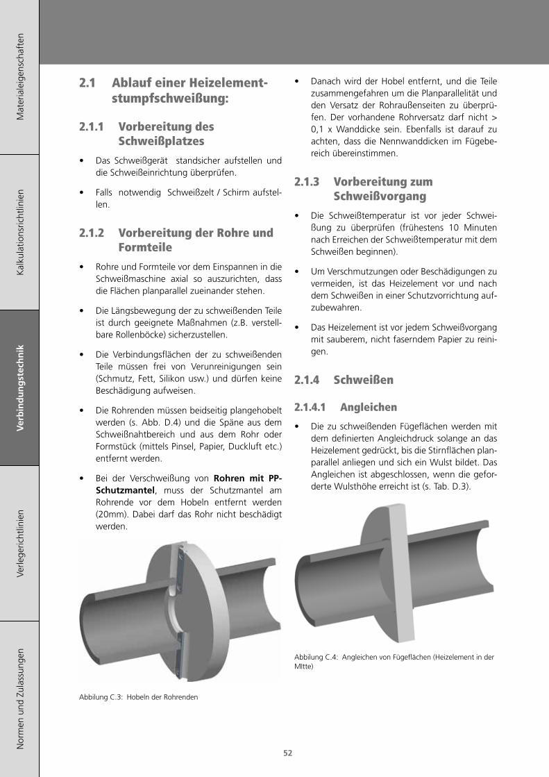
Mat
eria
leig
ensc
haft
enK
alku
latio
nsric
htlin
ien
Ver
bin
du
ng
stec
hn
ikVe
rlege
richt
linie
nN
orm
en u
nd Z
ulas
sung
en
52
2.1 Ablauf einer Heizelement-stumpfschweißung:
2.1.1 Vorbereitung des Schweißplatzes
• Das Schweißgerät standsicher aufstellen und die Schweißeinrichtung überprüfen.
• Falls notwendig Schweißzelt / Schirm aufstel-len.
2.1.2 Vorbereitung der Rohre und Formteile
• Rohre und Formteile vor dem Einspannen in die Schweißmaschine axial so auszurichten, dass die Flächen planparallel zueinander stehen.
• Die Längsbewegung der zu schweißenden Teile ist durch geeignete Maßnahmen (z.B. verstell-bare Rollenböcke) sicherzustellen.
• Die Verbindungsflächen der zu schweißenden Teile müssen frei von Verunreinigungen sein (Schmutz, Fett, Silikon usw.) und dürfen keine Beschädigung aufweisen.
• Die Rohrenden müssen beidseitig plangehobelt werden (s. Abb. D.4) und die Späne aus dem Schweißnahtbereich und aus dem Rohr oder Formstück (mittels Pinsel, Papier, Duckluft etc.) entfernt werden.
• Bei der Verschweißung von Rohren mit PP-Schutzmantel, muss der Schutzmantel am Rohrende vor dem Hobeln entfernt werden (20mm). Dabei darf das Rohr nicht beschädigt werden.
Abbilung C.3: Hobeln der Rohrenden
• Danach wird der Hobel entfernt, und die Teile zusammengefahren um die Planparallelität und den Versatz der Rohraußenseiten zu überprü-fen. Der vorhandene Rohrversatz darf nicht > 0,1 x Wanddicke sein. Ebenfalls ist darauf zu achten, dass die Nennwanddicken im Fügebe-reich übereinstimmen.
2.1.3 Vorbereitung zum Schweißvorgang
• Die Schweißtemperatur ist vor jeder Schwei-ßung zu überprüfen (frühestens 10 Minuten nach Erreichen der Schweißtemperatur mit dem Schweißen beginnen).
• Um Verschmutzungen oder Beschädigungen zu vermeiden, ist das Heizelement vor und nach dem Schweißen in einer Schutzvorrichtung auf-zubewahren.
• Das Heizelement ist vor jedem Schweißvorgang mit sauberem, nicht faserndem Papier zu reini-gen.
2.1.4 Schweißen
2.1.4.1 Angleichen
• Die zu schweißenden Fügeflächen werden mit dem definierten Angleichdruck solange an das Heizelement gedrückt, bis die Stirnflächen plan-parallel anliegen und sich ein Wulst bildet. Das Angleichen ist abgeschlossen, wenn die gefor-derte Wulsthöhe erreicht ist (s. Tab. D.3).
Abbilung C.4: Angleichen von Fügeflächen (Heizelement in der MItte)
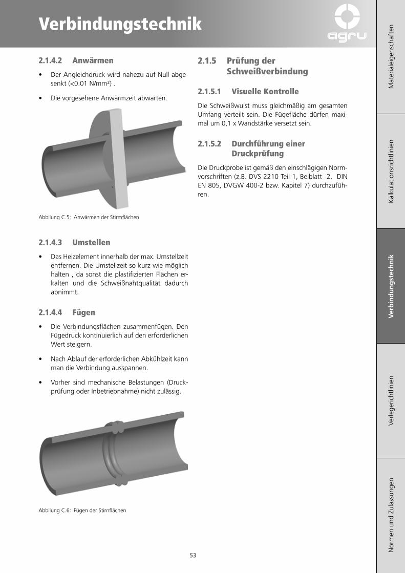
Verbindungstechnik
Mat
eria
leig
ensc
haft
enK
alku
latio
nsric
htlin
ien
Ver
bin
du
ng
stec
hn
ikVe
rlege
richt
linie
nN
orm
en u
nd Z
ulas
sung
en
53
2.1.4.2 Anwärmen
• Der Angleichdruck wird nahezu auf Null abge-senkt (<0.01 N/mm²) .
• Die vorgesehene Anwärmzeit abwarten.
Abbilung C.5: Anwärmen der Stirmflächen
2.1.4.3 Umstellen
• Das Heizelement innerhalb der max. Umstellzeit entfernen. Die Umstellzeit so kurz wie möglich halten , da sonst die plastifizierten Flächen er-kalten und die Schweißnahtqualität dadurch abnimmt.
2.1.4.4 Fügen
• Die Verbindungsflächen zusammenfügen. Den Fügedruck kontinuierlich auf den erforderlichen Wert steigern.
• Nach Ablauf der erforderlichen Abkühlzeit kann man die Verbindung ausspannen.
• Vorher sind mechanische Belastungen (Druck-prüfung oder Inbetriebnahme) nicht zulässig.
Abbilung C.6: Fügen der Stirnflächen
2.1.5 Prüfung der Schweißverbindung
2.1.5.1 Visuelle Kontrolle
Die Schweißwulst muss gleichmäßig am gesamten Umfang verteilt sein. Die Fügefläche dürfen maxi-mal um 0,1 x Wandstärke versetzt sein.
2.1.5.2 Durchführung einer Druckprüfung
Die Druckprobe ist gemäß den einschlägigen Norm-vorschriften (z.B. DVS 2210 Teil 1, Beiblatt 2, DIN EN 805, DVGW 400-2 bzw. Kapitel 7) durchzufüh-ren.
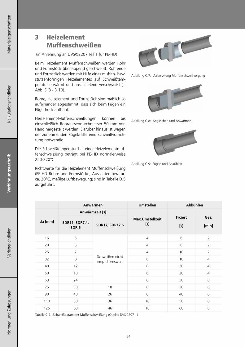
Mat
eria
leig
ensc
haft
enK
alku
latio
nsric
htlin
ien
Ver
bin
du
ng
stec
hn
ikVe
rlege
richt
linie
nN
orm
en u
nd Z
ulas
sung
en
54
3 Heizelement Muffenschweißen
(in Anlehnung an DVS©2207 Teil 1 für PE-HD)
Beim Heizelement Muffenschweißen werden Rohr und Formstück überlappend geschweißt. Rohrende und Formstück werden mit Hilfe eines muffen- bzw. stutzenförmigen Heizelementes auf Schweißtem-peratur erwärmt und anschließend verschweißt (s. Abb. D.8 - D.10).
Rohre, Heizelement und Formstück sind maßlich so aufeinander abgestimmt, dass sich beim Fügen ein Fügedruck aufbaut.
Heizelement-Muffenschweißungen können bis einschließlich Rohraussendurchmesser 50 mm von Hand hergestellt werden. Darüber hinaus ist wegen der zunehmenden Fügekräfte eine Schweißvorrich-tung notwendig.
Die Schweißtemperatur bei einer Heizelementmuf-fenschweissung beträgt bei PE-HD normalerweise 250-270°C
Richtwerte für die Heizelement Muffenschweißung (PE-HD Rohre und Formstücke, Aussentemperatur: ca. 20°C, mäßige Luftbewegung) sind in Tabelle D.5 aufgeführt.
Anwärmen Umstellen Abkühlen
da [mm]
Anwärmzeit [s]
Max.Umstellzeit [s]
Fixiert
[s]
Ges.
[min]SDR11, SDR7,4,
SDR 6SDR17, SDR17,6
16 5
Schweißen nicht empfehlenswert
4 6 2
20 5 4 6 2
25 7 4 10 2
32 8 6 10 4
40 12 6 20 4
50 18 6 20 4
63 24 8 30 6
75 30 18 8 30 6
90 40 26 8 40 6
110 50 36 10 50 8
125 60 46 10 60 8
Tabelle C.7: Schweißparameter Muffenschweißung (Quelle: DVS 2207-1)
Abbilung C.7: Vorbereitung Muffenschweißvorgang
Abbilung C.8: Angleichen und Anwärmen
Abbilung C.9: Fügen und Abkühlen
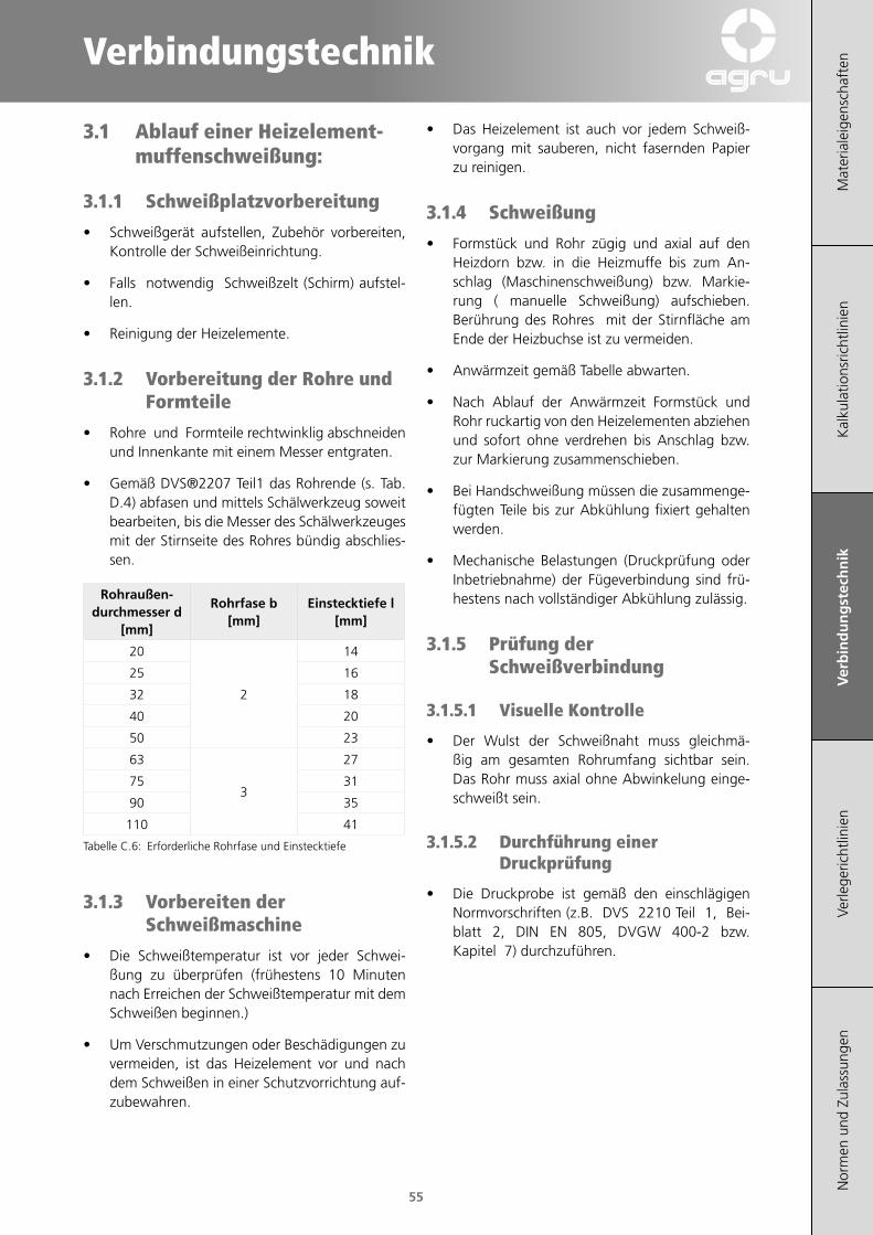
Verbindungstechnik
Mat
eria
leig
ensc
haft
enK
alku
latio
nsric
htlin
ien
Ver
bin
du
ng
stec
hn
ikVe
rlege
richt
linie
nN
orm
en u
nd Z
ulas
sung
en
55
3.1 Ablauf einer Heizelement-muffenschweißung:
3.1.1 Schweißplatzvorbereitung
• Schweißgerät aufstellen, Zubehör vorbereiten, Kontrolle der Schweißeinrichtung.
• Falls notwendig Schweißzelt (Schirm) aufstel-len.
• Reinigung der Heizelemente.
3.1.2 Vorbereitung der Rohre und Formteile
• Rohre und Formteile rechtwinklig abschneiden und Innenkante mit einem Messer entgraten.
• Gemäß DVS®2207 Teil1 das Rohrende (s. Tab. D.4) abfasen und mittels Schälwerkzeug soweit bearbeiten, bis die Messer des Schälwerkzeuges mit der Stirnseite des Rohres bündig abschlies-sen.
Rohraußen-durchmesser d
[mm]
Rohrfase b [mm]
Einstecktiefe l [mm]
20
2
14
25 16
32 18
40 20
50 23
63
3
27
75 31
90 35
110 41
Tabelle C.6: Erforderliche Rohrfase und Einstecktiefe
3.1.3 Vorbereiten der Schweißmaschine
• Die Schweißtemperatur ist vor jeder Schwei-ßung zu überprüfen (frühestens 10 Minuten nach Erreichen der Schweißtemperatur mit dem Schweißen beginnen.)
• Um Verschmutzungen oder Beschädigungen zu vermeiden, ist das Heizelement vor und nach dem Schweißen in einer Schutzvorrichtung auf-zubewahren.
• Das Heizelement ist auch vor jedem Schweiß-vorgang mit sauberen, nicht fasernden Papier zu reinigen.
3.1.4 Schweißung
• Formstück und Rohr zügig und axial auf den Heizdorn bzw. in die Heizmuffe bis zum An-schlag (Maschinenschweißung) bzw. Markie-rung ( manuelle Schweißung) aufschieben. Berührung des Rohres mit der Stirnfläche am Ende der Heizbuchse ist zu vermeiden.
• Anwärmzeit gemäß Tabelle abwarten.
• Nach Ablauf der Anwärmzeit Formstück und Rohr ruckartig von den Heizelementen abziehen und sofort ohne verdrehen bis Anschlag bzw. zur Markierung zusammenschieben.
• Bei Handschweißung müssen die zusammenge-fügten Teile bis zur Abkühlung fixiert gehalten werden.
• Mechanische Belastungen (Druckprüfung oder Inbetriebnahme) der Fügeverbindung sind frü-hestens nach vollständiger Abkühlung zulässig.
3.1.5 Prüfung der Schweißverbindung
3.1.5.1 Visuelle Kontrolle
• Der Wulst der Schweißnaht muss gleichmä-ßig am gesamten Rohrumfang sichtbar sein. Das Rohr muss axial ohne Abwinkelung einge-schweißt sein.
3.1.5.2 Durchführung einer Druckprüfung
• Die Druckprobe ist gemäß den einschlägigen Normvorschriften (z.B. DVS 2210 Teil 1, Bei-blatt 2, DIN EN 805, DVGW 400-2 bzw. Kapitel 7) durchzuführen.

Mat
eria
leig
ensc
haft
enK
alku
latio
nsric
htlin
ien
Ver
bin
du
ng
stec
hn
ikVe
rlege
richt
linie
nN
orm
en u
nd Z
ulas
sung
en
56
4 Heizwendelschweißen DIM 20-500mm monofilar
(in Anlehnung an DVS©2207 Teil 1 für PE-HD)
Beim Heizwendelschweißen mit monofilarem Schweißsystem werden die zu verbindenden Kom-ponenten mit Hilfe von Widerstandsdrähten (Heiz-wendel) erwärmt und dadurch verschweißt. Die Widerständsdrähte sind im Formteil komplett einge-bettet, dies bewirkt eine glatte Innenoberfläche und erleichtert somit die Reinigung und das Einführen der Rohrenden. Die Energiezufuhr erfolgt mit Hil-fe eines Schweißstromtransformators (Heizwendel-schweißgerät).
Die Schrumpfspannungen der Heizwendelformteile erzeugen den notwendigen Schweißdruck, der eine optimale Verschweißung sicherstellt.
Das Verfahren zeichnet sich durch die verwendete Sicherheitskleinspannung sowie durch einen hohen Automatisierungsgrad aus. Schweißungen können vor Ort und an unzugänglichen Stellen durchge-führt werden.
Abbilung C.10: Prinzip des monofilaren Heizwendelschweißens
Für die Verschweißung von Agru E-Formteilen soll-te bevorzugt ein Universalschweißgerät mit Bar-codeerkennung und Protokollierung herangezogen werden. Einfache Bedienung und lückenlose Nach-verfolgbarkeit der Schweißabläufe können somit garantiert werden.
4.1 BarcodeDer Barcode enthält alle benötigten Schweißpara-meter und ist so aufgebaut, dass er von allen gängi-gen Heizwendelschweißgeräten eingelesen werden kann. Auf den agru Heizwendelform teilen befindet sich neben dem Schweißcode auch ein Barcode für die Rückver folgbarkeit Dieser Code wird Trace abilitycode genannt und ermöglicht die Erfas-sung von chargen bezoge nen Angaben. Zur Unter-scheidung der beiden Codes werden zweifarbige Etiketten verwendet (s. Abb. D.12):
Abbilung C.11: Agru Barcode-Aufkleber
Schweißcode (weißer Hintergrund)
Stelle Beschreibung
1-2 Formteil
3-6 Hersteller
7-8 Abkühlzeit
9-11 Dimension
12 Energiezufuhr
13-14 Spannungsniveau
15-17 Widerstand
18 Toleranzbereich des Widerstands
19-21 Schweißzeit
22-23 Korrekturwert für Energie
24 Prüfziffen
Traceabilitycode (gelber Hintergrund)
Stelle Beschreibung
1-4 Hersteller
5-6 Formteil
7-9 Dimension
10-15 Seriennummer
16-17 Produktionsstandort
18 SDR-Klasse
19-22 Grundmaterial
23 Materialzustand
24 MRS
25 MFR
26 Prüfziffer

Verbindungstechnik
Mat
eria
leig
ensc
haft
enK
alku
latio
nsric
htlin
ien
Ver
bin
du
ng
stec
hn
ikVe
rlege
richt
linie
nN
orm
en u
nd Z
ulas
sung
en
57
4.2 Allgemeine SchweißeignungPE 80, PE 100 und PE 100-RC können grundsätzlich problemlos miteinander verschweißt werden.
Achtung: Das Rohr / E-Formteil mit der niedrigsten Druckstufe bestimmt die gesamte Druckstufe der Lei-tung (z.B. Rohre PN25 (SDR 7,4) mit E-Formteil PN 16 (SDR 11) verbunden –> ges. Leitung: PN16).
Die Verschweißbarkeit der E-Formteile ist mit folgenden SDR Rohrreihen geprüft und freigegeben:
E- Muffe
da [mm]
Schweißbare Rohre / Fittinge
SDR 33 SDR 26 SDR 17,6 SDR 17 SDR 13,6 SDR 11 SDR 9 SDR 7,4
SDR
11 (E
-Muf
fe)
20 Schweißbar mit Wanddicken ab s=2,5mm bis s= 3,5mm*
25 Schweißbar mit Wanddicken ab s=2,7mm bis s= 3,8mm*
32 x x x x x
40 x x
50 x x
63 x x
75 x x
90 x x
110 x x
125 x x
140 x x
160 x x
180 x
200 x x
225 x x
250 x
280 x
315 x x x
355 x x x
400 x x x
450 x x x x
500 x x x x
SDR
17 (E
-Muf
fe)
90 x x x x x
110 x x x x
160 x x x x
200 x x x x
225 x x x x
250 x x x x
280 x x x x
315 x x x x
355 x x x x
400 x x x x
450 x x x x
500 x x x x
*Dünnwandigere Rohre müssen mit Stützhülsen verschweißt werden.
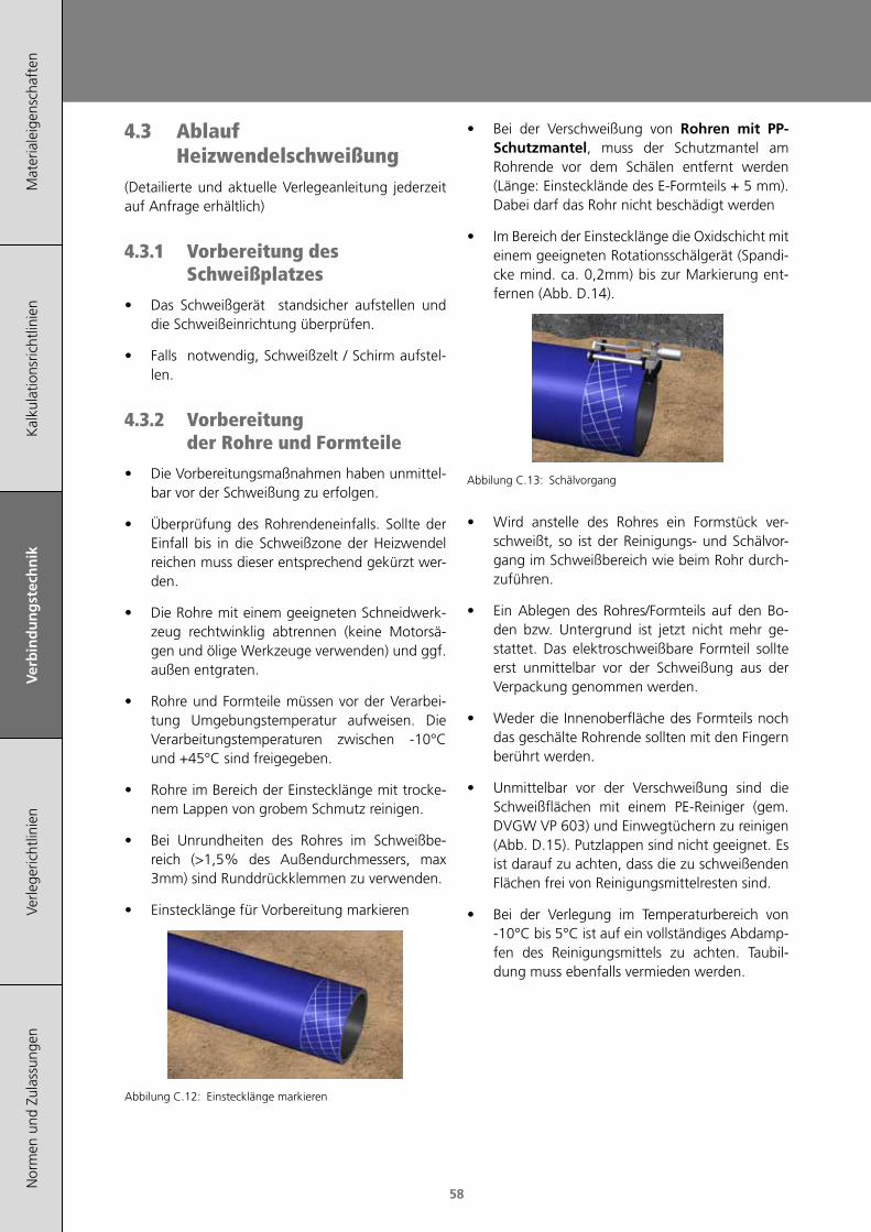
Mat
eria
leig
ensc
haft
enK
alku
latio
nsric
htlin
ien
Ver
bin
du
ng
stec
hn
ikVe
rlege
richt
linie
nN
orm
en u
nd Z
ulas
sung
en
58
4.3 Ablauf Heizwendelschweißung
(Detailierte und aktuelle Verlegeanleitung jederzeit auf Anfrage erhältlich)
4.3.1 Vorbereitung des Schweißplatzes
• Das Schweißgerät standsicher aufstellen und die Schweißeinrichtung überprüfen.
• Falls notwendig, Schweißzelt / Schirm aufstel-len.
4.3.2 Vorbereitung der Rohre und Formteile
• Die Vorbereitungsmaßnahmen haben unmittel-bar vor der Schweißung zu erfolgen.
• Überprüfung des Rohrendeneinfalls. Sollte der Einfall bis in die Schweißzone der Heizwendel reichen muss dieser entsprechend gekürzt wer-den.
• Die Rohre mit einem geeigneten Schneidwerk-zeug rechtwinklig abtrennen (keine Motorsä-gen und ölige Werkzeuge verwenden) und ggf. außen entgraten.
• Rohre und Formteile müssen vor der Verarbei-tung Umgebungstemperatur aufweisen. Die Verarbeitungstemperaturen zwischen -10°C und +45°C sind freigegeben.
• Rohre im Bereich der Einstecklänge mit trocke-nem Lappen von grobem Schmutz reinigen.
• Bei Unrundheiten des Rohres im Schweißbe-reich (>1,5% des Außendurchmessers, max 3mm) sind Runddrückklemmen zu verwenden.
• Einstecklänge für Vorbereitung markieren
Abbilung C.12: Einstecklänge markieren
• Bei der Verschweißung von Rohren mit PP-Schutzmantel, muss der Schutzmantel am Rohrende vor dem Schälen entfernt werden (Länge: Einstecklände des E-Formteils + 5 mm). Dabei darf das Rohr nicht beschädigt werden
• Im Bereich der Einstecklänge die Oxidschicht mit einem geeigneten Rotationsschälgerät (Spandi-cke mind. ca. 0,2mm) bis zur Markierung ent-fernen (Abb. D.14).
Abbilung C.13: Schälvorgang
• Wird anstelle des Rohres ein Formstück ver-schweißt, so ist der Reinigungs- und Schälvor-gang im Schweißbereich wie beim Rohr durch-zuführen.
• Ein Ablegen des Rohres/Formteils auf den Bo-den bzw. Untergrund ist jetzt nicht mehr ge-stattet. Das elektroschweißbare Formteil sollte erst unmittelbar vor der Schweißung aus der Verpackung genommen werden.
• Weder die Innenoberfläche des Formteils noch das geschälte Rohrende sollten mit den Fingern berührt werden.
• Unmittelbar vor der Verschweißung sind die Schweißflächen mit einem PE-Reiniger (gem. DVGW VP 603) und Einwegtüchern zu reinigen (Abb. D.15). Putzlappen sind nicht geeignet. Es ist darauf zu achten, dass die zu schweißenden Flächen frei von Reinigungsmittelresten sind.
• Bei der Verlegung im Temperaturbereich von -10°C bis 5°C ist auf ein vollständiges Abdamp-fen des Reinigungsmittels zu achten. Taubil-dung muss ebenfalls vermieden werden.
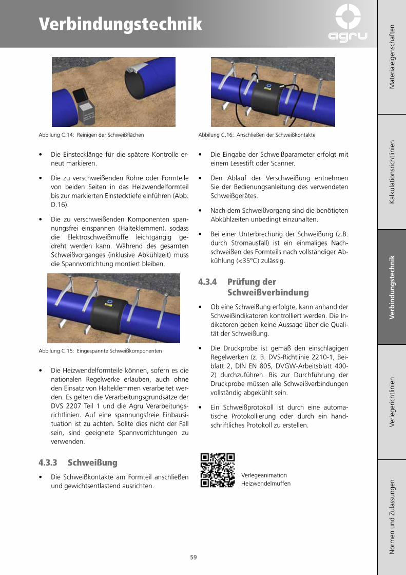
Verbindungstechnik
Mat
eria
leig
ensc
haft
enK
alku
latio
nsric
htlin
ien
Ver
bin
du
ng
stec
hn
ikVe
rlege
richt
linie
nN
orm
en u
nd Z
ulas
sung
en
59
Abbilung C.14: Reinigen der Schweißflächen
• Die Einstecklänge für die spätere Kontrolle er-neut markieren.
• Die zu verschweißenden Rohre oder Formteile von beiden Seiten in das Heizwendelformteil bis zur markierten Einstecktiefe einführen (Abb. D.16).
• Die zu verschweißenden Komponenten span-nungsfrei einspannen (Halteklemmen), sodass die Elektroschweißmuffe leichtgängig ge-dreht werden kann. Während des gesamten Schweißvorganges (inklusive Abkühlzeit) muss die Spannvorrichtung montiert bleiben.
Abbilung C.15: Eingespannte Schweißkomponenten
• Die Heizwendelformteile können, sofern es die nationalen Regelwerke erlauben, auch ohne den Einsatz von Halteklemmen verarbeitet wer-den. Es gelten die Verarbeitungsgrundsätze der DVS 2207 Teil 1 und die Agru Verarbeitungs-richtlinien. Auf eine spannungsfreie Einbausi-tuation ist zu achten. Sollte dies nicht der Fall sein, sind geeignete Spannvorrichtungen zu verwenden.
4.3.3 Schweißung
• Die Schweißkontakte am Formteil anschließen und gewichtsentlastend ausrichten.
Abbilung C.16: Anschließen der Schweißkontakte
• Die Eingabe der Schweißparameter erfolgt mit einem Lesestift oder Scanner.
• Den Ablauf der Verschweißung entnehmen Sie der Bedienungsanleitung des verwendeten Schweißgerätes.
• Nach dem Schweißvorgang sind die benötigten Abkühlzeiten unbedingt einzuhalten.
• Bei einer Unterbrechung der Schweißung (z.B. durch Stromausfall) ist ein einmaliges Nach-schweißen des Formteils nach vollständiger Ab-kühlung (<35°C) zulässig.
4.3.4 Prüfung der Schweißverbindung
• Ob eine Schweißung erfolgte, kann anhand der Schweißindikatoren kontrolliert werden. Die In-dikatoren geben keine Aussage über die Quali-tät der Schweißung.
• Die Druckprobe ist gemäß den einschlägigen Regelwerken (z. B. DVS-Richtlinie 2210-1, Bei-blatt 2, DIN EN 805, DVGW-Arbeitsblatt 400-2) durchzuführen. Bis zur Durchführung der Druckprobe müssen alle Schweißverbindungen vollständig abgekühlt sein.
• Ein Schweißprotokoll ist durch eine automa-tische Protokollierung oder durch ein hand-schriftliches Protokoll zu erstellen.
VerlegeanimationHeizwendelmuffen
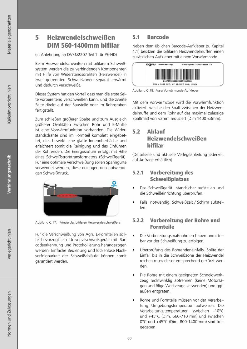
Mat
eria
leig
ensc
haft
enK
alku
latio
nsric
htlin
ien
Ver
bin
du
ng
stec
hn
ikVe
rlege
richt
linie
nN
orm
en u
nd Z
ulas
sung
en
60
5 Heizwendelschweißen DIM 560-1400mm bifilar
(in Anlehnung an DVS©2207 Teil 1 für PE-HD)
Beim Heizwendelschweißen mit bifilarem Schweiß-system werden die zu verbindenden Komponenten mit Hilfe von Widerstandsdrähten (Heizwendel) in zwei getrennten Schweißzonen separat erwärmt und dadurch verschweißt.
Dieses System hat den Vorteil dass man die erste Sei-te vorbereitend verschweißen kann, und die zweite Seite direkt auf der Baustelle oder im Rohrgraben fertigstellt.
Zum schließen größerer Spalte und zum Ausgleich größerer Ovalitäten zwischen Rohr und E-Muffe ist eine Vorwärmfunktion vorhanden. Die Wider-standsdrähte sind im Formteil komplett eingebet-tet, dies bewirkt eine glatte Innenoberfläche und erleichtert somit die Reinigung und das Einführen der Rohrenden. Die Energiezufuhr erfolgt mit Hilfe eines Schweißstromtransformators (Schweißgerät). Für eine optimale Verschweißung sollen Spanngurte verwendet werden, diese erzeugen den notwendi-gen Schweißdruck.
Abbilung C.17: Prinzip des bifilaren Heizwendelschweißens
Für die Verschweißung von Agru E-Formteilen soll-te bevorzugt ein Universalschweißgerät mit Bar-codeerkennung und Protokollierung herangezogen werden. Einfache Bedienung und lückenlose Nach-verfolgbarkeit der Schweißabläufe können somit garantiert werden.
5.1 BarcodeNeben dem üblichen Barcode-Aufkleber (s. Kapitel 4.1) besitzen die bifilaren Heizwendelmuffen einen zusätzlichen Aufkleber mit einem Vorwärmcode.
Abbilung C.18: Agru Vorwärmcode-Aufkleber
Mit dem Vorwärmcode wird die Vorwärmfunktion aktiviert, welche den Spalt zwischen der Heizwen-delmuffe und dem Rohr auf das maximal zulässige Spaltmaß von <2mm reduziert (Dim 1400 <3mm).
5.2 Ablauf Heizwendelschweißen bifilar
(Detailierte und aktuelle Verlegeanleitung jederzeit auf Anfrage erhältlich)
5.2.1 Vorbereitung des Schweißplatzes
• Das Schweißgerät standsicher aufstellen und die Schweißeinrichtung überprüfen.
• Falls notwendig, Schweißzelt / Schirm aufstel-len.
5.2.2 Vorbereitung der Rohre und Formteile
• Die Vorbereitungsmaßnahmen haben unmittel-bar vor der Schweißung zu erfolgen.
• Überprüfung des Rohrendeneinfalls. Sollte der Einfall bis in die Schweißzone der Heizwendel reichen muss dieser entsprechend gekürzt wer-den.
• Die Rohre mit einem geeigneten Schneidwerk-zeug rechtwinklig abtrennen (keine Motorsä-gen und ölige Werkzeuge verwenden) und ggf. außen entgraten.
• Rohre und Formteile müssen vor der Verarbei-tung Umgebungstemperatur aufweisen. Die Verarbeitungstemperaturen zwischen -10°C und +45°C (Dim. 560-710 mm) und zwischen 0°C und +45°C (Dim. 800-1400 mm) sind frei-gegeben.
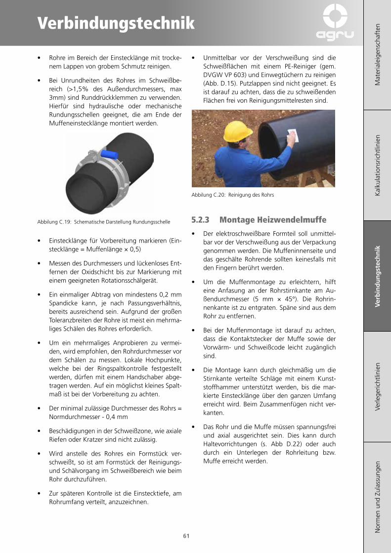
Verbindungstechnik
Mat
eria
leig
ensc
haft
enK
alku
latio
nsric
htlin
ien
Ver
bin
du
ng
stec
hn
ikVe
rlege
richt
linie
nN
orm
en u
nd Z
ulas
sung
en
61
• Rohre im Bereich der Einstecklänge mit trocke-nem Lappen von grobem Schmutz reinigen.
• Bei Unrundheiten des Rohres im Schweißbe-reich (>1,5% des Außendurchmessers, max 3mm) sind Runddrückklemmen zu verwenden. Hierfür sind hydraulische oder mechanische Rundungsschellen geeignet, die am Ende der Muffeneinstecklänge montiert werden.
Abbilung C.19: Schematische Darstellung Rundungsschelle
• Einstecklänge für Vorbereitung markieren (Ein-stecklänge = Muffenlänge × 0,5)
• Messen des Durchmessers und lückenloses Ent-fernen der Oxidschicht bis zur Markierung mit einem geeigneten Rotationsschälgerät.
• Ein einmaliger Abtrag von mindestens 0,2 mm Spandicke kann, je nach Passungsverhältnis, bereits ausreichend sein. Aufgrund der großen Toleranzbreiten der Rohre ist meist ein mehrma-liges Schälen des Rohres erforderlich.
• Um ein mehrmaliges Anprobieren zu vermei-den, wird empfohlen, den Rohrdurchmesser vor dem Schälen zu messen. Lokale Hochpunkte, welche bei der Ringspaltkontrolle festgestellt werden, dürfen mit einem Handschaber abge-tragen werden. Auf ein möglichst kleines Spalt-maß ist bei der Vorbereitung zu achten.
• Der minimal zulässige Durchmesser des Rohrs = Normdurchmesser - 0,4 mm
• Beschädigungen in der Schweißzone, wie axiale Riefen oder Kratzer sind nicht zulässig.
• Wird anstelle des Rohres ein Formstück ver-schweißt, so ist am Formstück der Reinigungs- und Schälvorgang im Schweißbereich wie beim Rohr durchzuführen.
• Zur späteren Kontrolle ist die Einstecktiefe, am Rohrumfang verteilt, anzuzeichnen.
• Unmittelbar vor der Verschweißung sind die Schweißflächen mit einem PE-Reiniger (gem. DVGW VP 603) und Einwegtüchern zu reinigen (Abb. D.15). Putzlappen sind nicht geeignet. Es ist darauf zu achten, dass die zu schweißenden Flächen frei von Reinigungsmittelresten sind.
Abbilung C.20: Reinigung des Rohrs
5.2.3 Montage Heizwendelmuffe
• Der elektroschweißbare Formteil soll unmittel-bar vor der Verschweißung aus der Verpackung genommen werden. Die Muffeninnenseite und das geschälte Rohrende sollten keinesfalls mit den Fingern berührt werden.
• Um die Muffenmontage zu erleichtern, hilft eine Anfasung an der Rohrstirnkante am Au-ßendurchmesser (5 mm × 45°). Die Rohrin-nenkante ist zu entgraten. Späne sind aus dem Rohr zu entfernen.
• Bei der Muffenmontage ist darauf zu achten, dass die Kontaktstecker der Muffe sowie der Vorwärm- und Schweißcode leicht zugänglich sind.
• Die Montage kann durch gleichmäßig um die Stirnkante verteilte Schläge mit einem Kunst-stoffhammer unterstützt werden, bis die mar-kierte Einstecklänge über den ganzen Umfang erreicht wird. Beim Zusammenfügen nicht ver-kanten.
• Das Rohr und die Muffe müssen spannungsfrei und axial ausgerichtet sein. Dies kann durch Haltevorrichtungen (s. Abb D.22) oder auch durch ein Unterlegen der Rohrleitung bzw. Muffe erreicht werden.

Mat
eria
leig
ensc
haft
enK
alku
latio
nsric
htlin
ien
Ver
bin
du
ng
stec
hn
ikVe
rlege
richt
linie
nN
orm
en u
nd Z
ulas
sung
en
62
Abbilung C.21: Montage der Halteklemmen und Ausrichten des Rohrs
• Rohre dürfen nicht unter Eigenlast oder Bie-gespannung in der Muffe stecken. Die Span-nungsfreiheit ist bis zum vollständigen Ablaufen der Kühlzeit aufrechtzuerhalten.
• Das zweite, mit der Muffe zu verschweißen-de Rohr, ist ebenfalls so vorzubereiten und zu montieren wie oben beschrieben.
5.2.4 Montage Spanngurte
Anschließend müssen beide 50 mm breiten Spann-gurte angelegt werden. Diese sind separat zu be-stellen (Artikelcode: SAGSPANNG01), und können nach Ablauf der Kühlzeit wieder verwendet werden. Ein zusätzliches Werkzeug ist nicht erlaubt.
• Beide Spanngurte müssen in die Nuten einge-legt und befestigt werden wie in Abb. D.23-D.25 beschrieben
• Ratschenhebel öffnen und loses Ende in die Schlitzwelle einfädeln und durchziehen.
Abbilung C.22: Einfädeln des Spanngurtes
• Gurt spannen und so lange von Hand mittels Ratschenhebel festziehen bis dieser stramm an der Muffe anliegt und von Hand nicht mehr ver-rutscht werden kann. Danach den Ratschenhe-bel in Schließstellung bringen.
Abbilung C.23: Spannen des Gurtes.
• Nach Ablauf der Kühlzeit zum Lösen den Funk-tionsschieber ziehen und den Ratschenhebel um ca. 180° bis zum Endanschlag öffnen.
Abbilung C.24: Öffnen des Spanngurtes
5.2.5 Schweißung
• Die beiden Steckanschlüsse der Muffe sind mit den Anschlussbuchsen des Schweißgerätes zu verbinden. Auf ausreichende Geräteleistung der Schweißmaschine, gegebenenfalls auch des Generators ist zu achten.
• Geeignete Schweißmaschinen:
• Polycontrol plus
• HST 300 pricon+
• HST 300 print+
• Zur Minimierung des Ringspalts die Vorwärmung der jeweiligen Muffenseite mit dem Vorwärm-code durchführen. Der Ringspalt kann mit einer mitgelieferten Spaltlehre gemessen werden.

Verbindungstechnik
Mat
eria
leig
ensc
haft
enK
alku
latio
nsric
htlin
ien
Ver
bin
du
ng
stec
hn
ikVe
rlege
richt
linie
nN
orm
en u
nd Z
ulas
sung
en
63
• Nach dem Vorwärmen ist der Ringspalt der ersten Muffenseite im angegebenen Haltezeit-raum zu überprüfen. Wenn dieser in Ordnung ist, kann die Schweißung der ersten Muffensei-te innerhalb der Toleranz der Haltezeit gestartet werden. Ist der Spalt zu groß, ist die Vorwär-mung zu wiederholen.
Abbilung C.25: Kontrolle des Ringspaltes mit der Spaltlehre
• Mit der zweiten Seite der Heizwendelmuffe ent-sprechend verfahren.
• Nach der Vorwärmung kann die Schweißung gestartet werden . Die Eingabe der Schweißpa-rameter erfolgt mit einem Lesestift oder Scan-ner über den Schweißcode.
• Den korrekten Ablauf der Schweißung entneh-men Sie der Bedienungsanleitung des verwen-deten Schweißgerätes.
• Nach dem Schweißvorgang sind die benötigten Abkühlzeiten unbedingt einzuhalten.
• Bei einer Unterbrechung der Schweißung (z.B durch einen Stromausfall) ist ein einmalige Nachschweißen der Muffe nach vollständiger Abkühlung (<35°C) zulässig, wobei das Vor-wärmen und die Spaltkontrolle zu wiederholen sind.
5.2.6 Prüfung der Schweißverbindung
• Die Druckprobe ist gemäß den einschlägigen Regelwerken (z. B. DVS-Richtlinie 2210-1, Bei-blatt 2, DIN EN 805, DVGW-Arbeitsblatt 400-2) durchzuführen. Bis zur Durchführung der Druckprobe müssen alle Schweißverbindungen vollständig abgekühlt sein.
• Ein Schweißprotokoll ist durch eine automa-tische Protokollierung oder durch ein hand-schriftliches Protokoll zu erstellen.
• Nach Ablauf der Kühlzeit können beide Gurte von der Muffe entfernt werden.
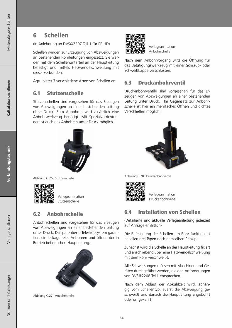
Mat
eria
leig
ensc
haft
enK
alku
latio
nsric
htlin
ien
Ver
bin
du
ng
stec
hn
ikVe
rlege
richt
linie
nN
orm
en u
nd Z
ulas
sung
en
64
6 Schellen(in Anlehnung an DVS©2207 Teil 1 für PE-HD)
Schellen werden zur Erzeugung von Abzweigungen an bestehenden Rohrleitungen eingesetzt. Sie wer-den mit dem Schellenunterteil an der Hauptleitung befestigt und mittels Heizwendelschweißung mit dieser verbunden.
Agru bietet 3 verschiedene Arten von Schellen an:
6.1 Stutzenschelle Stutzenschellen sind vorgesehen für das Erzeugen von Abzweigungen an einer bestehenden Leitung ohne Druck. Zum Anbohren wird zusätzlich eine Anbohrwerkzeug benötigt. Mit Spezialvorrichtun-gen ist auch das Anbohren unter Druck möglich.
Abbilung C.26: Stutzenschelle
VerlegeanimationStutzenschelle
6.2 Anbohrschelle Anbohrschellen sind vorgesehen für das Erzeugen von Abzweigungen an einer bestehenden Leitung unter Druck. Das patentierte Teleskopsystem garan-tiert ein leckagefreies Anbohren und öffnen der in Betrieb befindlichen Hauptleitung.
Abbilung C.27: Anbohrschelle
VerlegeanimationAnbohrschelle
Nach dem Anbohrvorgang wird die Öffnung für das Betätigungswerkzeug mit einer Schraub- oder Schweißkappe verschlossen.
6.3 Druckanbohrventil Druckanbohrventile sind vorgesehen für das Er-zeugen von Abzweigungen an einer bestehenden Leitung unter Druck. Im Gegensatz zur Anbohr-schelle ist hier ein mehrfaches Öffnen und dichtes Verschließen möglich.
Abbilung C.28: Druckanbohrventil
VerlegeanimationDruckanbohrventil
6.4 Installation von Schellen(Detailierte und aktuelle Verlegeanleitung jederzeit auf Anfrage erhältlich)
Die Befestigung der Schellen am Rohr funktioniert bei allen drei Typen nach demselben Prinzip:
Zunächst wird die Schelle an der Hauptleitung fixiert und anschließend über eine Heizwendelschweißung mit dem Rohr verschweißt.
Alle Schweißungen müssen mit Maschinen und Ge-räten durchgeführt werden, die den Anforderungen von DVS®2208 Teil1 entsprechen.
Nach dem Ablauf der Abkühlzeit wird, abhän-gig vom Schellentyp, zuerst die Abzweigung ge-schweißt und danach die Hauptleitung angebohrt oder umgekehrt.
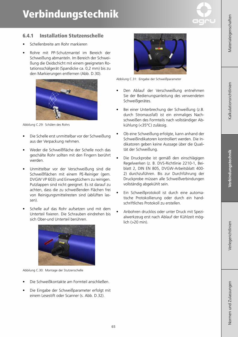
Verbindungstechnik
Mat
eria
leig
ensc
haft
enK
alku
latio
nsric
htlin
ien
Ver
bin
du
ng
stec
hn
ikVe
rlege
richt
linie
nN
orm
en u
nd Z
ulas
sung
en
65
6.4.1 Installation Stutzenschelle
• Schellenbreite am Rohr markieren
• Rohre mit PP-Schutzmantel im Bereich der Schweißung abmanteln. Im Bereich der Schwei-ßung die Oxidschicht mit einem geeigneten Ro-tationsschälgerät (Spandicke ca. 0,2 mm) bis zu den Markierungen entfernen (Abb. D.30).
Abbilung C.29: Schälen des Rohrs
• Die Schelle erst unmittelbar vor der Schweißung aus der Verpackung nehmen.
• Weder die Schweißfläche der Schelle noch das geschälte Rohr sollten mit den Fingern berührt werden.
• Unmittelbar vor der Verschweißung sind die Schweißflächen mit einem PE-Reiniger (gem. DVGW VP 603) und Einwegtüchern zu reinigen. Putzlappen sind nicht geeignet. Es ist darauf zu achten, dass die zu schweißenden Flächen frei von Reinigungsmittelresten sind (ablüften las-sen).
• Schelle auf das Rohr aufsetzen und mit dem Unterteil fixieren. Die Schrauben eindrehen bis sich Ober-und Unterteil berühren.
Abbilung C.30: Montage der Stutzenschelle
• Die Schweißkontakte am Formteil anschließen.
• Die Eingabe der Schweißparameter erfolgt mit einem Lesestift oder Scanner (s. Abb. D.32).
Abbilung C.31: Eingabe der Schweißparameter
• Den Ablauf der Verschweißung entnehmen Sie der Bedienungsanleitung des verwendeten Schweißgerätes.
• Bei einer Unterbrechung der Schweißung (z.B. durch Stromausfall) ist ein einmaliges Nach-schweißen des Formteils nach vollständiger Ab-kühlung (<35°C) zulässig.
• Ob eine Schweißung erfolgte, kann anhand der Schweißindikatoren kontrolliert werden. Die In-dikatoren geben keine Aussage über die Quali-tät der Schweißung.
• Die Druckprobe ist gemäß den einschlägigen Regelwerken (z. B. DVS-Richtlinie 2210-1, Bei-blatt 2, DIN EN 805, DVGW-Arbeitsblatt 400-2) durchzuführen. Bis zur Durchführung der Druckprobe müssen alle Schweißverbindungen vollständig abgekühlt sein.
• Ein Schweißprotokoll ist durch eine automa-tische Protokollierung oder durch ein hand-schriftliches Protokoll zu erstellen.
• Anbohren drucklos oder unter Druck mit Spezi-alwerkzeug erst nach Ablauf der Kühlzeit mög-lich (>20 min).
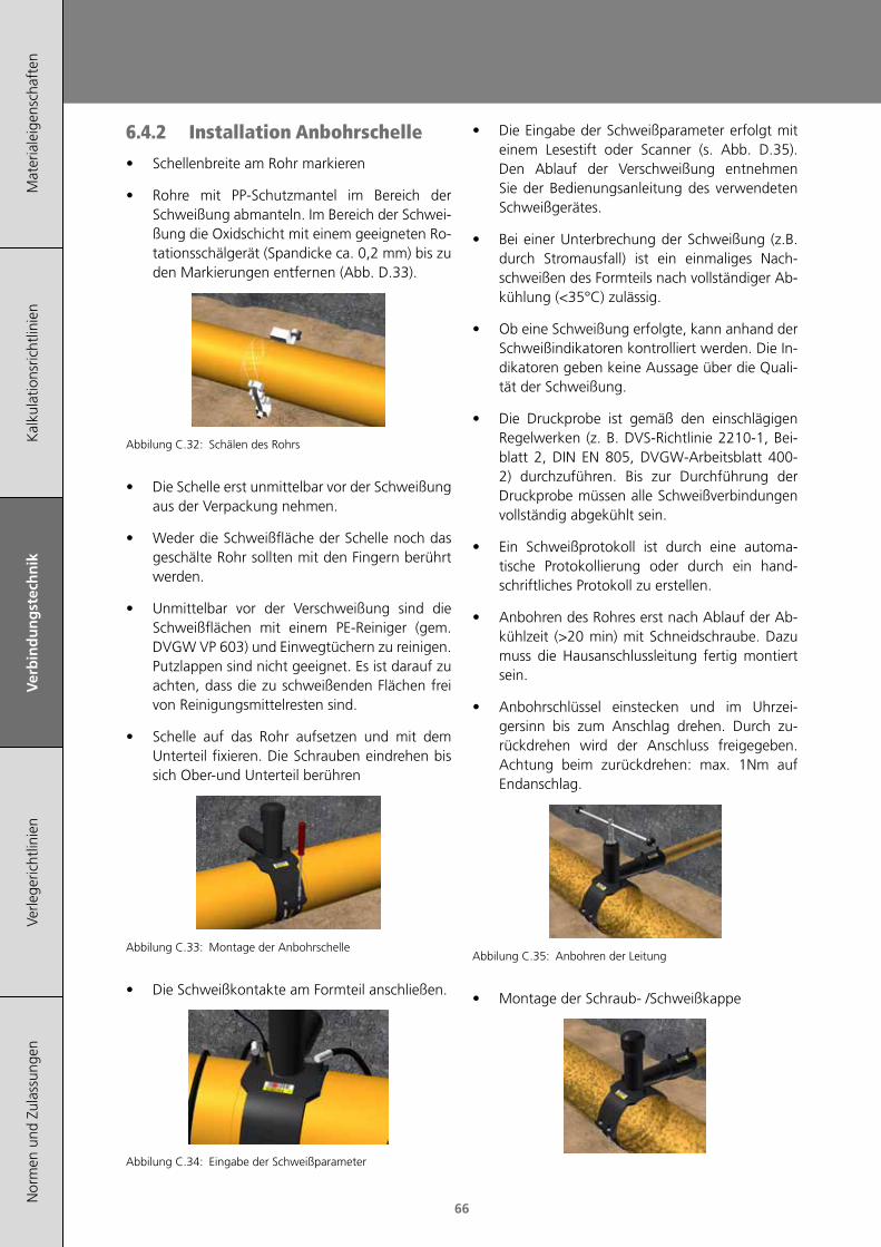
Mat
eria
leig
ensc
haft
enK
alku
latio
nsric
htlin
ien
Ver
bin
du
ng
stec
hn
ikVe
rlege
richt
linie
nN
orm
en u
nd Z
ulas
sung
en
66
6.4.2 Installation Anbohrschelle
• Schellenbreite am Rohr markieren
• Rohre mit PP-Schutzmantel im Bereich der Schweißung abmanteln. Im Bereich der Schwei-ßung die Oxidschicht mit einem geeigneten Ro-tationsschälgerät (Spandicke ca. 0,2 mm) bis zu den Markierungen entfernen (Abb. D.33).
Abbilung C.32: Schälen des Rohrs
• Die Schelle erst unmittelbar vor der Schweißung aus der Verpackung nehmen.
• Weder die Schweißfläche der Schelle noch das geschälte Rohr sollten mit den Fingern berührt werden.
• Unmittelbar vor der Verschweißung sind die Schweißflächen mit einem PE-Reiniger (gem. DVGW VP 603) und Einwegtüchern zu reinigen. Putzlappen sind nicht geeignet. Es ist darauf zu achten, dass die zu schweißenden Flächen frei von Reinigungsmittelresten sind.
• Schelle auf das Rohr aufsetzen und mit dem Unterteil fixieren. Die Schrauben eindrehen bis sich Ober-und Unterteil berühren
Abbilung C.33: Montage der Anbohrschelle
• Die Schweißkontakte am Formteil anschließen.
Abbilung C.34: Eingabe der Schweißparameter
• Die Eingabe der Schweißparameter erfolgt mit einem Lesestift oder Scanner (s. Abb. D.35).Den Ablauf der Verschweißung entnehmen Sie der Bedienungsanleitung des verwendeten Schweißgerätes.
• Bei einer Unterbrechung der Schweißung (z.B. durch Stromausfall) ist ein einmaliges Nach-schweißen des Formteils nach vollständiger Ab-kühlung (<35°C) zulässig.
• Ob eine Schweißung erfolgte, kann anhand der Schweißindikatoren kontrolliert werden. Die In-dikatoren geben keine Aussage über die Quali-tät der Schweißung.
• Die Druckprobe ist gemäß den einschlägigen Regelwerken (z. B. DVS-Richtlinie 2210-1, Bei-blatt 2, DIN EN 805, DVGW-Arbeitsblatt 400-2) durchzuführen. Bis zur Durchführung der Druckprobe müssen alle Schweißverbindungen vollständig abgekühlt sein.
• Ein Schweißprotokoll ist durch eine automa-tische Protokollierung oder durch ein hand-schriftliches Protokoll zu erstellen.
• Anbohren des Rohres erst nach Ablauf der Ab-kühlzeit (>20 min) mit Schneidschraube. Dazu muss die Hausanschlussleitung fertig montiert sein.
• Anbohrschlüssel einstecken und im Uhrzei-gersinn bis zum Anschlag drehen. Durch zu-rückdrehen wird der Anschluss freigegeben. Achtung beim zurückdrehen: max. 1Nm auf Endanschlag.
Abbilung C.35: Anbohren der Leitung
• Montage der Schraub- /Schweißkappe

Verbindungstechnik
Mat
eria
leig
ensc
haft
enK
alku
latio
nsric
htlin
ien
Ver
bin
du
ng
stec
hn
ikVe
rlege
richt
linie
nN
orm
en u
nd Z
ulas
sung
en
67
6.4.3 Installation Druckanbohrventil DAV
• Ventilbreite am Rohr markieren
• Rohre mit PP-Schutzmantel im Bereich der Schweißung abmanteln. Im Bereich der Schwei-ßung die Oxidschicht mit einem geeigneten Ro-tationsschälgerät (Spandicke ca. 0,2 mm) bis zu den Markierungen entfernen (Abb. D.33)
Abbilung C.36: Schälen des Rohrs
• Das Ventil erst unmittelbar vor der Schweißung aus der Verpackung nehmen.
• Weder die Schweißfläche des Ventils noch das geschälte Rohr sollten mit den Fingern berührt werden.
• Unmittelbar vor der Verschweißung sind die Schweißflächen mit einem PE-Reiniger (gem. DVGW VP 603) und Einwegtüchern zu reinigen. Putzlappen sind nicht geeignet. Es ist darauf zu achten, dass die zu schweißenden Flächen frei von Reinigungsmittelresten sind.
• Das Ventil auf das Rohr aufsetzen und durch Einrasten von Ober- und Unterteil am Rohr fixie-ren. Zur Aufbringung des nötigen Schweiß-druckes sind die vormontierten Schrauben am Druckanbohrventil (DAV) mittels Innen-sechskant in die integrierten Muttern im Unter-teil zu schrauben. Es muss sichergestellt wer-den, dass sich Ober- und Unterteil vollflächig berühren.
Abbilung C.37: Montage des Druckanbohrventils
• Die Schweißkontakte am Formteil anschließen.
Abbilung C.38: Eingabe der Schweißparameter
• Die Eingabe der Schweißparameter erfolgt mit einem Lesestift oder Scanner (s. Abb. D.39).
• Den Ablauf der Verschweißung entnehmen Sie der Bedienungsanleitung des verwendeten Schweißgerätes.
• Bei einer Unterbrechung der Schweißung (z.B. durch Stromausfall) ist ein einmaliges Nach-schweißen des Formteils nach vollständiger Ab-kühlung (<35°C) zulässig.
• Ob eine Schweißung erfolgte, kann anhand der Schweißindikatoren kontrolliert werden. Die In-dikatoren geben keine Aussage über die Quali-tät der Schweißung.
• Die Druckprobe ist gemäß den einschlägigen Regelwerken (z. B. DVS-Richtlinie 2210-1, Bei-blatt 2, DIN EN 805, DVGW-Arbeitsblatt 400-2) durchzuführen. Bis zur Durchführung der Druckprobe müssen alle Schweißverbindungen vollständig abgekühlt sein.
• Ein Schweißprotokoll ist durch eine automa-tische Protokollierung oder durch ein hand-schriftliches Protokoll zu erstellen.
• Anbohren des Rohres erst nach Ablauf der Abkühlzeit (>20 min) mit Schneidschraube. Anbohrschlüssel im Uhrzeigersinn bis zum An-schlag drehen. Durch zurückdrehen wird der Anschluss freigegeben. Um die Ventilstellung zu fixieren, soll mit leichter Handkraft gegen den oberen bzw. unteren Anschlag gedreht werden.
Abbilung C.39: Anbohren der Leitung
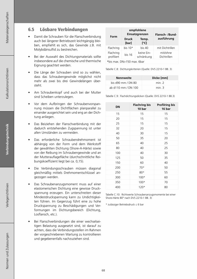
Mat
eria
leig
ensc
haft
enK
alku
latio
nsric
htlin
ien
Ver
bin
du
ng
stec
hn
ikVe
rlege
richt
linie
nN
orm
en u
nd Z
ulas
sung
en
68
6.5 Lösbare Verbindungen• Damit die Schrauben für die Flanschverbindung
auch bei längerer Betriebszeit leichtgängig blei-ben, empfiehlt es sich, das Gewinde z.B. mit Molybdänsulfid zu bestreichen.
• Bei der Auswahl des Dichtungsmaterials sollte insbesondere auf die chemische und thermische Eignung geachtet werden.
• Die Länge der Schrauben sind so zu wählen, dass das Schraubengewinde möglichst nicht mehr als zwei bis drei Gewindelängen über-steht.
• Am Schraubenkopf und auch bei der Mutter sind Scheiben unterzulegen.
• Vor dem Aufbringen der Schraubenvorspan-nung müssen die Dichtflächen planparallel zu einander ausgerichtet sein und eng an der Dich-tung anliegen.
• Das Beiziehen der Flanschverbindung mit der dadurch entstehenden Zugspannung ist unter allen Umständen zu vermeiden.
• Das erforderliche Schraubendrehmoment ist abhängig von der Form und dem Werkstoff der gewählten Dichtung (Shore-A-Härte) sowie von der Reibung im Schraubengewinde und an der Mutterauflagefläche (durchschnittliche Rei-bungskoeffizient liegt bei ca. 0,15).
• Die Verbindungsschrauben müssen diagonal gleichmäßig mittels Drehmomentschlüssel an-gezogen werden.
• Das Schraubenanzugsmoment muss auf einer elastomerischen Dichtung eine gewisse Druck-spannung erzeugen. Ein unterschreiten dieser Mindestdruckspannung kann zu Undichtigkei-ten führen. Im Gegenzug führt eine zu hohe Druckspannung zu Beschädigungen und Ver-formungen im Dichtungsbereich (Dichtung, Losflansch, etc.).
• Bei Flanschverbindungen die einer wechselsei-tigen Belastung ausgesetzt sind, ist darauf zu achten, dass die Verbindungsstellen im Rahmen der vorgeschriebenen Wartung zu kontrollieren und gegebenenfalls nachzuziehen sind.
Form
empfohlene Einsatzgrenzen Flansch- /Bund-
ausführungDruck [bar]
Temp. [°C]
Flachring bis 10* bis 40 mit Dichtrillen
Flachring profiliert
bis 16keine Ein-
schränkungmit/ohne Dichtrillen
*bis max. DN>150 max. 6bar
Tabelle C.8: Dichtungskriterien (Quelle: DVS 2210-1 BB. 3)
Nennweite Dicke [mm]
bis d90 mm / DN 80 min. 2
ab d110 mm / DN 100 min. 3
Tabelle C.9: Flachdichtungsdicken (Quelle: DVS 2210-1 BB.3)
DNFlachring bis
10 barProfilring bis
16 bar
15 15 15
20 15 15
25 15 15
32 20 15
40 30 15
50 35 20
65 40 25
80 40 25
100 40 30
125 50 35
150 60 40
200 70* 50
250 80* 55
300 100* 60
350 100* 70
400 120* 80
Tabelle C.10: Richtwerte Schraubenanzugsmomente bei einer Shore-Härte 80° nach DVS 2210-1 BB. 3) * zulässiger Betriebsdruck ≤ 6 bar

Verbindungstechnik
Mat
eria
leig
ensc
haft
enK
alku
latio
nsric
htlin
ien
Ver
bin
du
ng
stec
hn
ikVe
rlege
richt
linie
nN
orm
en u
nd Z
ulas
sung
en
69
7 DruckprüfungNachstehend sind drei Druckprüf-Verfahren nach gültigen Regelwerken beschrieben. Diese werden unterteilt in Prüfungen von frei verlegten oder erd-verlegten Leitungen für Wasser- oder Gasversor-gung. Die Druckprüfungen können nach nationalen Anforderungen von den hier beschiebenen Verfah-ren abweichen.
Die Innendruckprüfung ist am fertig installierten Rohrsystem vorzunehmen. Die Beanspruchung durch den Innendruck muss oberhalb der Betriebs-belastung liegen und soll den experimentellen Nachweis der Betriebssicherheit darstellen. Das Prü-fen der Rohrleitung mit einem Innendruck unterhalb des Nenndrucks der Rohrleitungsteile ist nur in Aus-nahmefällen anzuwenden.
7.1 Druckprüfung für freiverlegte Leitungen
(in Anlehnung an DVS 2210-1 Beiblatt 2)
Generell gibt es 3 Arten von Innendruckprüfungen:
- die Vorprüfung
- die Hauptprüfung
- die Kurzzeitprüfung
Das Ergebnis der Innendruckprüfung ist, einschließ-lich Angaben zu den Randbedingungen, in einem Protokoll festzuhalten. Eine kontinuierliche Druck- und Temperaturaufzeichnung ist vorzunehmen.
7.1.1 Vorprüfung
Die Vorprüfung dient dazu, das Rohrleitungssys-tem auf die eigentliche Prüfung (Hauptprüfung) vorzubereiten. Im Verlauf der Vorprüfung wird sich im Rohrleitungssystem ein Spannungs-Dehnungs- Gleichgewicht in Verbindung mit einer Volumenzu-nahme einstellen.
Dabei kommt es zu einem werkstoffabhängigen Druckabfall, der ein wiederholtes Nachpumpen zur Wiederherstellung des Prüfdruckes sowie häufig ein Nachziehen der Flanschverbindungsschrauben er-forderlich macht.
7.1.2 Hauptprüfung
Die Hauptprüfung folgt unmittelbar der Vorprü-fung. Im Rahmen der Hauptprüfung kann bei etwa gleichbleibenden Rohrwandtemperaturen ein we-sentlich geringerer Druckabfall erwartet werden, so dass sich ein Nachpumpen zur Wiederherstellung des Prüfdruckes erübrigt. Die Kontrollen können sich im Wesentlichen auf die Dichtheit der Flansch-verbindungen und auf eventuelle Lageveränderun-gen der Rohrleitung konzentrieren.
7.1.3 Kurzzeitprüfung
Die Kurzprüfung stellt einen Sonderfall dar, da sich in der zur Verfügung stehenden Zeit nach all-gemeiner Erfahrung kein Spannungs-Dehnungs-Gleichgewicht einstellt. Unzulänglichkeiten an den Verbindungsstellen können unter Umständen durch kurzzeitige Belastungen nicht erkannt werden, was dem Sinn einer Prüfung nicht entspricht.
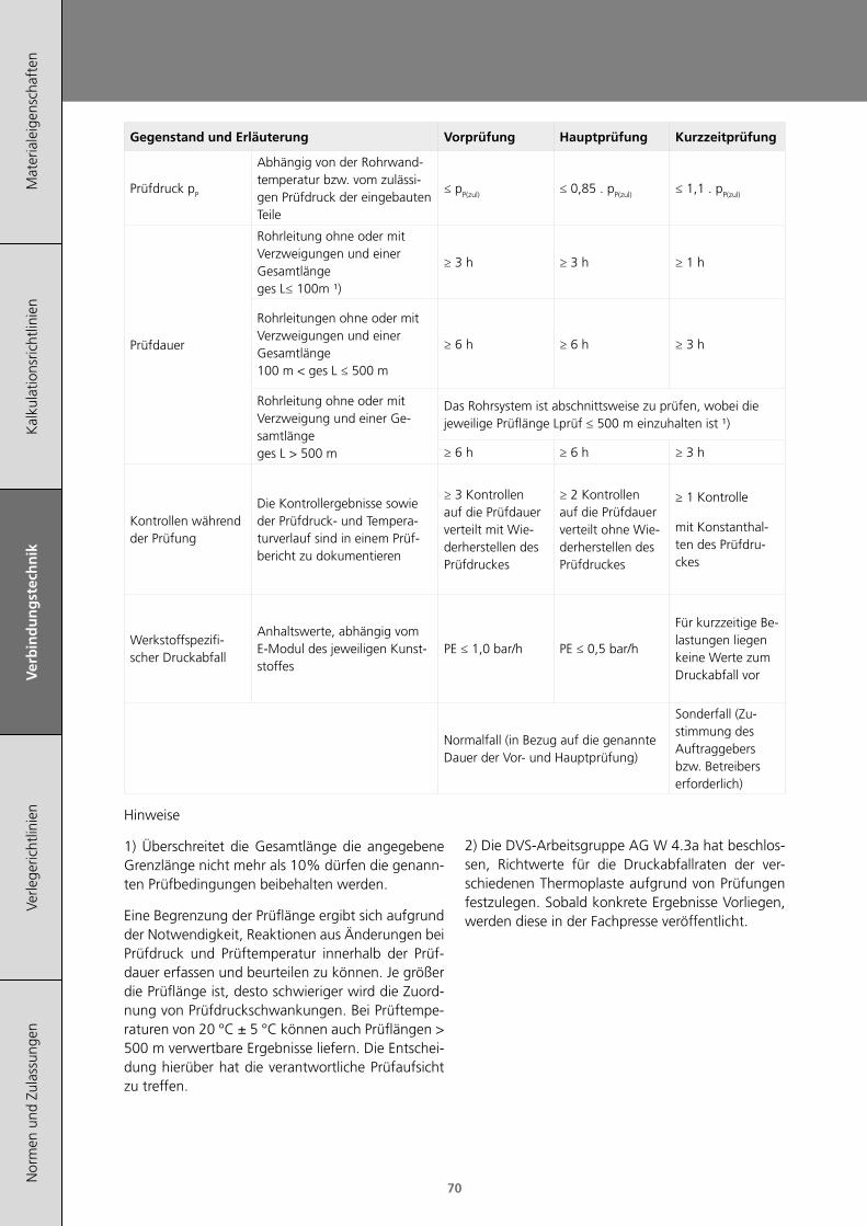
Mat
eria
leig
ensc
haft
enK
alku
latio
nsric
htlin
ien
Ver
bin
du
ng
stec
hn
ikVe
rlege
richt
linie
nN
orm
en u
nd Z
ulas
sung
en
70
Gegenstand und Erläuterung Vorprüfung Hauptprüfung Kurzzeitprüfung
Prüfdruck pP
Abhängig von der Rohrwand-temperatur bzw. vom zulässi-gen Prüfdruck der eingebauten Teile
≤ pP(zul) ≤ 0,85 . pP(zul) ≤ 1,1 . pP(zul)
Prüfdauer
Rohrleitung ohne oder mit Verzweigungen und einer Gesamtlänge ges L≤ 100m ¹)
≥ 3 h ≥ 3 h ≥ 1 h
Rohrleitungen ohne oder mit Verzweigungen und einer Gesamtlänge 100 m < ges L ≤ 500 m
≥ 6 h ≥ 6 h ≥ 3 h
Rohrleitung ohne oder mit Verzweigung und einer Ge-samtlänge ges L > 500 m
Das Rohrsystem ist abschnittsweise zu prüfen, wobei die jeweilige Prüflänge Lprüf ≤ 500 m einzuhalten ist ¹)
≥ 6 h ≥ 6 h ≥ 3 h
Kontrollen während der Prüfung
Die Kontrollergebnisse sowie der Prüfdruck- und Tempera-turverlauf sind in einem Prüf-bericht zu dokumentieren
≥ 3 Kontrollen auf die Prüfdauer verteilt mit Wie-derherstellen des Prüfdruckes
≥ 2 Kontrollen auf die Prüfdauer verteilt ohne Wie-derherstellen des Prüfdruckes
≥ 1 Kontrolle
mit Konstanthal-ten des Prüfdru-ckes
Werkstoffspezifi-scher Druckabfall
Anhaltswerte, abhängig vom E-Modul des jeweiligen Kunst-stoffes
PE ≤ 1,0 bar/h PE ≤ 0,5 bar/h
Für kurzzeitige Be-lastungen liegen keine Werte zum Druckabfall vor
Normalfall (in Bezug auf die genannte Dauer der Vor- und Hauptprüfung)
Sonderfall (Zu-stimmung des Auftraggebers bzw. Betreibers erforderlich)
Hinweise
1) Überschreitet die Gesamtlänge die angegebene Grenzlänge nicht mehr als 10% dürfen die genann-ten Prüfbedingungen beibehalten werden.
Eine Begrenzung der Prüflänge ergibt sich aufgrund der Notwendigkeit, Reaktionen aus Änderungen bei Prüfdruck und Prüftemperatur innerhalb der Prüf-dauer erfassen und beurteilen zu können. Je größer die Prüflänge ist, desto schwieriger wird die Zuord-nung von Prüfdruckschwankungen. Bei Prüftempe-raturen von 20 °C ± 5 °C können auch Prüflängen > 500 m verwertbare Ergebnisse liefern. Die Entschei-dung hierüber hat die verantwortliche Prüfaufsicht zu treffen.
2) Die DVS-Arbeitsgruppe AG W 4.3a hat beschlos-sen, Richtwerte für die Druckabfallraten der ver-schiedenen Thermoplaste aufgrund von Prüfungen festzulegen. Sobald konkrete Ergebnisse Vorliegen, werden diese in der Fachpresse veröffentlicht.
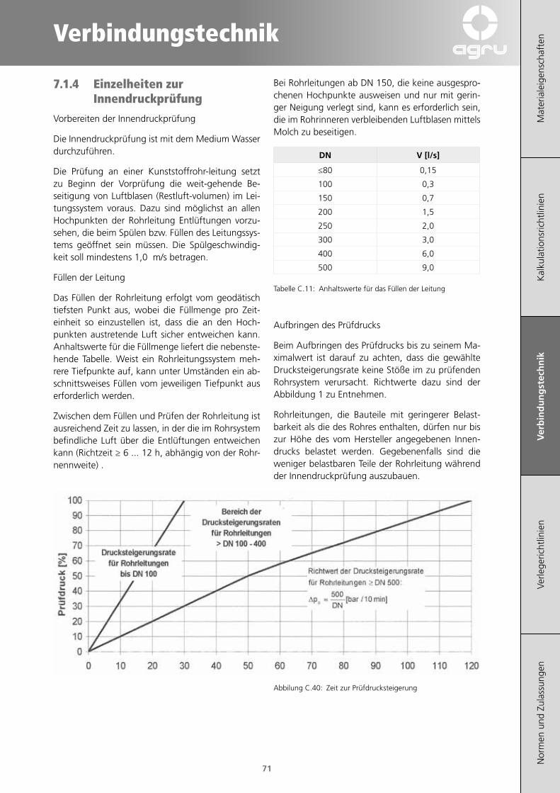
Verbindungstechnik
Mat
eria
leig
ensc
haft
enK
alku
latio
nsric
htlin
ien
Ver
bin
du
ng
stec
hn
ikVe
rlege
richt
linie
nN
orm
en u
nd Z
ulas
sung
en
71
7.1.4 Einzelheiten zur Innendruckprüfung
Vorbereiten der Innendruckprüfung
Die Innendruckprüfung ist mit dem Medium Wasser durchzuführen.
Die Prüfung an einer Kunststoffrohr-leitung setzt zu Beginn der Vorprüfung die weit-gehende Be-seitigung von Luftblasen (Restluft-volumen) im Lei-tungssystem voraus. Dazu sind möglichst an allen Hochpunkten der Rohrleitung Entlüftungen vorzu-sehen, die beim Spülen bzw. Füllen des Leitungssys-tems geöffnet sein müssen. Die Spülgeschwindig-keit soll mindestens 1,0 m/s betragen.
Füllen der Leitung
Das Füllen der Rohrleitung erfolgt vom geodätisch tiefsten Punkt aus, wobei die Füllmenge pro Zeit-einheit so einzustellen ist, dass die an den Hoch-punkten austretende Luft sicher entweichen kann. Anhaltswerte für die Füllmenge liefert die nebenste-hende Tabelle. Weist ein Rohrleitungssystem meh-rere Tiefpunkte auf, kann unter Umständen ein ab-schnittsweises Füllen vom jeweiligen Tiefpunkt aus erforderlich werden.
Zwischen dem Füllen und Prüfen der Rohrleitung ist ausreichend Zeit zu lassen, in der die im Rohrsystem befindliche Luft über die Entlüftungen entweichen kann (Richtzeit ≥ 6 ... 12 h, abhängig von der Rohr-nennweite) .
Bei Rohrleitungen ab DN 150, die keine ausgespro-chenen Hochpunkte ausweisen und nur mit gerin-ger Neigung verlegt sind, kann es erforderlich sein, die im Rohrinneren verbleibenden Luftblasen mittels Molch zu beseitigen.
DN V [l/s]
≤80 0,15
100 0,3
150 0,7
200 1,5
250 2,0
300 3,0
400 6,0
500 9,0
Tabelle C.11: Anhaltswerte für das Füllen der Leitung
Aufbringen des Prüfdrucks
Beim Aufbringen des Prüfdrucks bis zu seinem Ma-ximalwert ist darauf zu achten, dass die gewählte Drucksteigerungsrate keine Stöße im zu prüfenden Rohrsystem verursacht. Richtwerte dazu sind der Abbildung 1 zu Entnehmen.
Rohrleitungen, die Bauteile mit geringerer Belast-barkeit als die des Rohres enthalten, dürfen nur bis zur Höhe des vom Hersteller angegebenen Innen-drucks belastet werden. Gegebenenfalls sind die weniger belastbaren Teile der Rohrleitung während der Innendruckprüfung auszubauen.
Abbilung C.40: Zeit zur Prüfdrucksteigerung
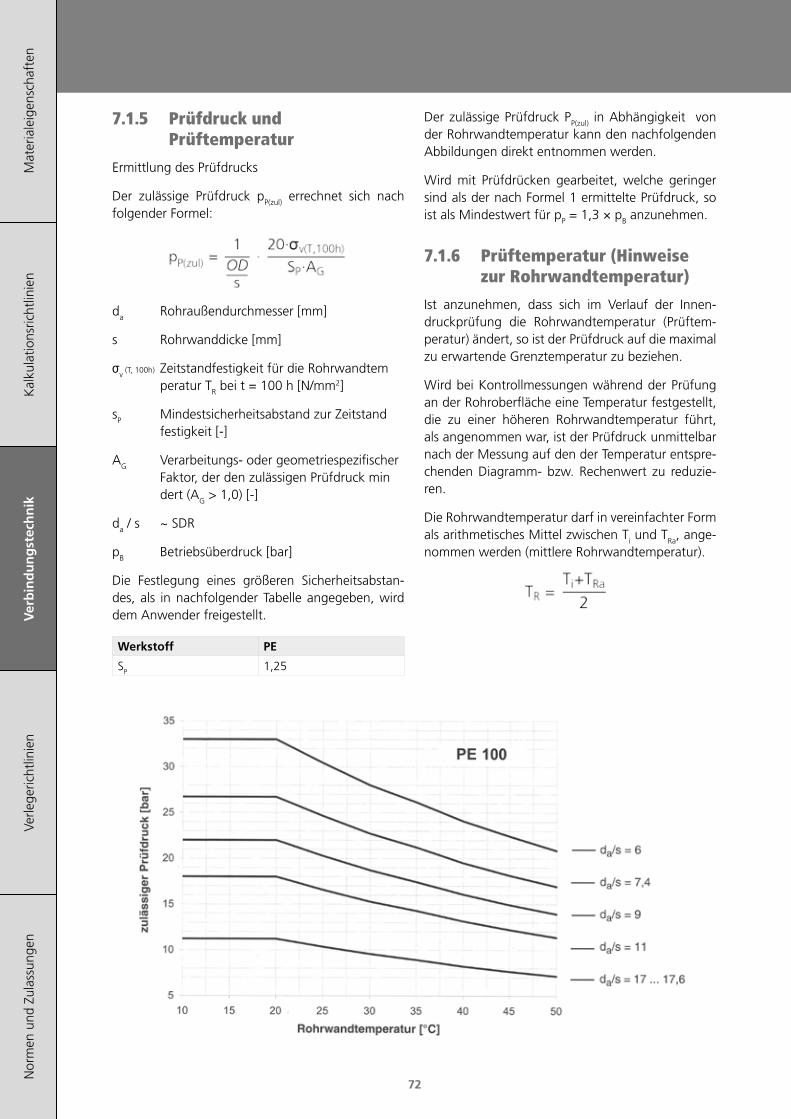
Mat
eria
leig
ensc
haft
enK
alku
latio
nsric
htlin
ien
Ver
bin
du
ng
stec
hn
ikVe
rlege
richt
linie
nN
orm
en u
nd Z
ulas
sung
en
72
7.1.5 Prüfdruck und Prüftemperatur
Ermittlung des Prüfdrucks
Der zulässige Prüfdruck pP(zul) errechnet sich nach folgender Formel:
da Rohraußendurchmesser [mm]
s Rohrwanddicke [mm]
σv (T, 100h) Zeitstandfestigkeit für die Rohrwandtem peratur TR bei t = 100 h [N/mm2]
sP Mindestsicherheitsabstand zur Zeitstand festigkeit [-]
AG Verarbeitungs- oder geometriespezifischer Faktor, der den zulässigen Prüfdruck min dert (AG > 1,0) [-]
da / s ~ SDR
pB Betriebsüberdruck [bar]
Die Festlegung eines größeren Sicherheitsabstan-des, als in nachfolgender Tabelle angegeben, wird dem Anwender freigestellt.
Werkstoff PE
SP 1,25
Der zulässige Prüfdruck PP(zul) in Abhängigkeit von der Rohrwandtemperatur kann den nachfolgenden Abbildungen direkt entnommen werden.
Wird mit Prüfdrücken gearbeitet, welche geringer sind als der nach Formel 1 ermittelte Prüfdruck, so ist als Mindestwert für pP = 1,3 × pB anzunehmen.
7.1.6 Prüftemperatur (Hinweise zur Rohrwandtemperatur)
Ist anzunehmen, dass sich im Verlauf der Innen-druckprüfung die Rohrwandtemperatur (Prüftem-peratur) ändert, so ist der Prüfdruck auf die maximal zu erwartende Grenztemperatur zu beziehen.
Wird bei Kontrollmessungen während der Prüfung an der Rohroberfläche eine Temperatur festgestellt, die zu einer höheren Rohrwandtemperatur führt, als angenommen war, ist der Prüfdruck unmittelbar nach der Messung auf den der Temperatur entspre-chenden Diagramm- bzw. Rechenwert zu reduzie-ren.
Die Rohrwandtemperatur darf in vereinfachter Form als arithmetisches Mittel zwischen Ti und TRa, ange-nommen werden (mittlere Rohrwandtemperatur).
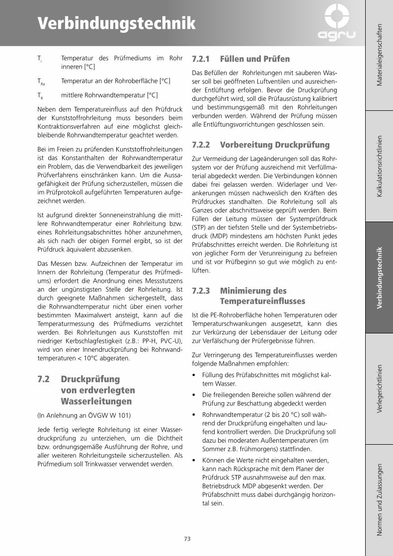
Verbindungstechnik
Mat
eria
leig
ensc
haft
enK
alku
latio
nsric
htlin
ien
Ver
bin
du
ng
stec
hn
ikVe
rlege
richt
linie
nN
orm
en u
nd Z
ulas
sung
en
73
Ti Temperatur des Prüfmediums im Rohr inneren [°C]
TRa Temperatur an der Rohroberfläche [°C]
TR mittlere Rohrwandtemperatur [°C]
Neben dem Temperatureinfluss auf den Prüfdruck der Kunststoffrohrleitung muss besonders beim Kontraktionsverfahren auf eine möglichst gleich-bleibende Rohrwandtemperatur geachtet werden.
Bei im Freien zu prüfenden Kunststoffrohrleitungen ist das Konstanthalten der Rohrwandtemperatur ein Problem, das die Verwendbarkeit des jeweiligen Prüfverfahrens einschränken kann. Um die Aussa-gefähigkeit der Prüfung sicherzustellen, müssen die im Prüfprotokoll aufgeführten Temperaturen aufge-zeichnet werden.
Ist aufgrund direkter Sonneneinstrahlung die mitt-lere Rohrwandtemperatur einer Rohrleitung bzw. eines Rohrleitungsabschnittes höher anzunehmen, als sich nach der obigen Formel ergibt, so ist der Prüfdruck äquivalent abzusenken.
Das Messen bzw. Aufzeichnen der Temperatur im lnnern der Rohrleitung (Temperatur des Prüfmedi-ums) erfordert die Anordnung eines Messstutzens an der ungünstigsten Stelle der Rohrleitung. Ist durch geeignete Maßnahmen sichergestellt, dass die Rohrwandtemperatur nicht über einen vorher bestimmten Maximalwert ansteigt, kann auf die Temperaturmessung des Prüfmediums verzichtet werden. Bei Rohrleitungen aus Kunststoffen mit niedriger Kerbschlagfestigkeit (z.B.: PP-H, PVC-U), wird von einer Innendruckprüfung bei Rohrwand-temperaturen < 10°C abgeraten.
7.2 Druckprüfung von erdverlegten Wasserleitungen
(In Anlehnung an ÖVGW W 101)
Jede fertig verlegte Rohrleitung ist einer Wasser-druckprüfung zu unterziehen, um die Dichtheit bzw. ordnungsgemäße Ausführung der Rohre, und aller weiteren Rohrleitungsteile sicherzustellen. Als Prüfmedium soll Trinkwasser verwendet werden.
7.2.1 Füllen und Prüfen
Das Befüllen der Rohrleitungen mit sauberen Was-ser soll bei geöffneten Luftventilen und ausreichen-der Entlüftung erfolgen. Bevor die Druckprüfung durchgeführt wird, soll die Prüfausrüstung kalibriert und bestimmungsgemäß mit den Rohrleitungen verbunden werden. Während der Prüfung müssen alle Entlüftungsvorrichtungen geschlossen sein.
7.2.2 Vorbereitung Druckprüfung
Zur Vermeidung der Lageänderungen soll das Rohr-system vor der Prüfung ausreichend mit Verfüllma-terial abgedeckt werden. Die Verbindungen können dabei frei gelassen werden. Widerlager und Ver-ankerungen müssen nachweislich den Kräften des Prüfdruckes standhalten. Die Rohrleitung soll als Ganzes oder abschnittsweise geprüft werden. Beim Füllen der Leitung müssen der Systemprüfdruck (STP) an der tiefsten Stelle und der Systembetriebs-druck (MDP) mindestens am höchsten Punkt jedes Prüfabschnittes erreicht werden. Die Rohrleitung ist von jeglicher Form der Verunreinigung zu befreien und ist vor Prüfbeginn so gut wie möglich zu ent-lüften.
7.2.3 Minimierung des Temperatureinflusses
Ist die PE-Rohroberfläche hohen Temperaturen oder Temperaturschwankungen ausgesetzt, kann dies zur Verkürzung der Lebensdauer der Leitung oder zur Verfälschung der Prüfergebnisse führen.
Zur Verringerung des Temperatureinflusses werden folgende Maßnahmen empfohlen:
• Füllung des Prüfabschnittes mit möglichst kal-tem Wasser.
• Die freiliegenden Bereiche sollen während der Prüfung zur Beschattung abgedeckt werden
• Rohrwandtemperatur (2 bis 20 °C) soll wäh-rend der Druckprüfung eingehalten und lau-fend kontrolliert werden. Die Druckprüfung soll dazu bei moderaten Außentemperaturen (im Sommer z.B. frühmorgens) stattfinden.
• Können die Werte nicht eingehalten werden, kann nach Rücksprache mit dem Planer der Prüfdruck STP ausnahmsweise auf den max. Betriebsdruck MDP abgesenkt werden. Der Prüfabschnitt muss dabei durchgängig horizon-tal sein.
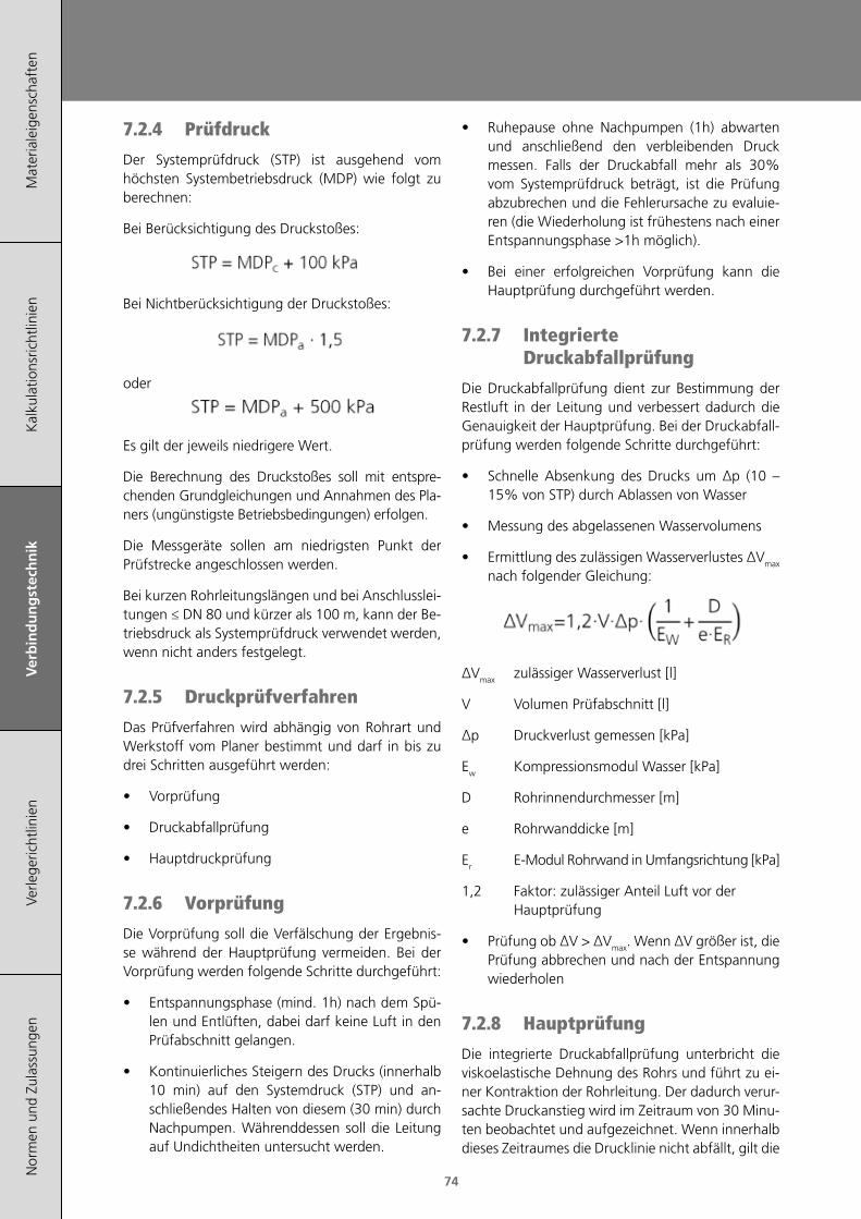
Mat
eria
leig
ensc
haft
enK
alku
latio
nsric
htlin
ien
Ver
bin
du
ng
stec
hn
ikVe
rlege
richt
linie
nN
orm
en u
nd Z
ulas
sung
en
74
7.2.4 Prüfdruck
Der Systemprüfdruck (STP) ist ausgehend vom höchsten Systembetriebsdruck (MDP) wie folgt zu berechnen:
Bei Berücksichtigung des Druckstoßes:
Bei Nichtberücksichtigung der Druckstoßes:
oder
Es gilt der jeweils niedrigere Wert.
Die Berechnung des Druckstoßes soll mit entspre-chenden Grundgleichungen und Annahmen des Pla-ners (ungünstigste Betriebsbedingungen) erfolgen.
Die Messgeräte sollen am niedrigsten Punkt der Prüfstrecke angeschlossen werden.
Bei kurzen Rohrleitungslängen und bei Anschlusslei-tungen ≤ DN 80 und kürzer als 100 m, kann der Be-triebsdruck als Systemprüfdruck verwendet werden, wenn nicht anders festgelegt.
7.2.5 Druckprüfverfahren
Das Prüfverfahren wird abhängig von Rohrart und Werkstoff vom Planer bestimmt und darf in bis zu drei Schritten ausgeführt werden:
• Vorprüfung
• Druckabfallprüfung
• Hauptdruckprüfung
7.2.6 Vorprüfung
Die Vorprüfung soll die Verfälschung der Ergebnis-se während der Hauptprüfung vermeiden. Bei der Vorprüfung werden folgende Schritte durchgeführt:
• Entspannungsphase (mind. 1h) nach dem Spü-len und Entlüften, dabei darf keine Luft in den Prüfabschnitt gelangen.
• Kontinuierliches Steigern des Drucks (innerhalb 10 min) auf den Systemdruck (STP) und an-schließendes Halten von diesem (30 min) durch Nachpumpen. Währenddessen soll die Leitung auf Undichtheiten untersucht werden.
• Ruhepause ohne Nachpumpen (1h) abwarten und anschließend den verbleibenden Druck messen. Falls der Druckabfall mehr als 30% vom Systemprüfdruck beträgt, ist die Prüfung abzubrechen und die Fehlerursache zu evaluie-ren (die Wiederholung ist frühestens nach einer Entspannungsphase >1h möglich).
• Bei einer erfolgreichen Vorprüfung kann die Hauptprüfung durchgeführt werden.
7.2.7 Integrierte Druckabfallprüfung
Die Druckabfallprüfung dient zur Bestimmung der Restluft in der Leitung und verbessert dadurch die Genauigkeit der Hauptprüfung. Bei der Druckabfall-prüfung werden folgende Schritte durchgeführt:
• Schnelle Absenkung des Drucks um Δp (10 – 15% von STP) durch Ablassen von Wasser
• Messung des abgelassenen Wasservolumens
• Ermittlung des zulässigen Wasserverlustes ΔVmax nach folgender Gleichung:
ΔVmax zulässiger Wasserverlust [l]
V Volumen Prüfabschnitt [l]
Δp Druckverlust gemessen [kPa]
Ew Kompressionsmodul Wasser [kPa]
D Rohrinnendurchmesser [m]
e Rohrwanddicke [m]
Er E-Modul Rohrwand in Umfangsrichtung [kPa]
1,2 Faktor: zulässiger Anteil Luft vor der Hauptprüfung
• Prüfung ob ΔV > ΔVmax. Wenn ΔV größer ist, die Prüfung abbrechen und nach der Entspannung wiederholen
7.2.8 Hauptprüfung
Die integrierte Druckabfallprüfung unterbricht die viskoelastische Dehnung des Rohrs und führt zu ei-ner Kontraktion der Rohrleitung. Der dadurch verur-sachte Druckanstieg wird im Zeitraum von 30 Minu-ten beobachtet und aufgezeichnet. Wenn innerhalb dieses Zeitraumes die Drucklinie nicht abfällt, gilt die
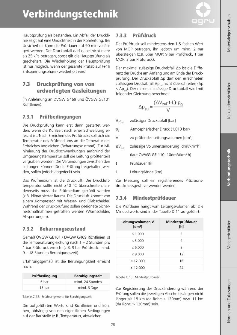
Verbindungstechnik
Mat
eria
leig
ensc
haft
enK
alku
latio
nsric
htlin
ien
Ver
bin
du
ng
stec
hn
ikVe
rlege
richt
linie
nN
orm
en u
nd Z
ulas
sung
en
75
Hauptprüfung als bestanden. Ein Abfall der Druckli-nie zeigt auf eine Undichtheit in der Rohrleitung. Bei Unsicherheit kann die Prüfdauer auf 90 min verlän-gert werden. Der Druckabfall darf dabei nicht mehr als 25 kPa betragen, sonst gilt die Hauptprüfung als gescheitert. Die Wiederholung der Hauptprüfung ist nur möglich, wenn der gesamte Prüfablauf (+1h Entspannungsphase) wiederholt wird.
7.3 Druckprüfung von von erdverlegten Gasleitungen
(In Anlehnung an DVGW G469 und ÖVGW GE101 Richtlinien).
7.3.1 Prüfbedingungen
Die Druckprüfung kann erst dann gestartet wer-den, wenn die Kühlzeit nach einer Schweißung er-reicht ist. Nach Erreichen des Prüfdrucks soll sich die Temperatur des Prüfmediums an die Temeratur des Erdreiches angleichen (Beharrungszustand). Zur Mi-nimierung der Druckschwankungen aufgrund der Umgebungstemperatur soll die Leitung größtenteils vergraben werden. Die Verbindungen zwischen den Leitungen können für die Prüfung freigehalten wer-den, sollen jedoch abgedeckt sein.
Das Prüfmedium ist die Druckluft. Die Druckluft-temperatur sollte nicht >40 °C überschreiten, an-dererseits muss das Prüfmedium gekühlt werden (z.B. klimatisierter Raum). Die Druckluft kommt von einem Kompressor mit Wasser- und Ölabscheider. Während der Druckprüfung sollen geeignete Sicher-heitsmaßnahmen getroffen werden (Warnschilder, Absperrungen).
7.3.2 Beharrungszustand
Gemäß ÖVGW GE101 / DVGW G469 Richtlinien ist die Temperaturangleichung nach 1 – 2 Stunden pro 1 bar Prüfdruck erreicht (z.B. 9 bar Prüfdruck: mind. 9 – 18 Stunden Beruhigungszeit).
Erfahrungsgemäß ist die Beruhigungszeit erreicht nach:
Prüfbedingung Beruhigungszeit
6 bar mind. 24 Stunden
15 bar mind. 3 Tage
Tabelle C.12: Erfahrungswerte für Beruhigungszeit
Die aufgeführten Werte sind Richtlinien und kön-nen, abhängig von den eigentlichen Bedingungen auf der Baustelle (z.B. Temperatur), abweichen.
7.3.3 Prüfdruck
Der Prüfdruck soll mindestens den 1,5-fachen Wert von MOP betragen, ihn jedoch um mind. 2 bar übersteigen (z.B. 6bar MOP: 9 bar Prüfdruck, 1 bar MOP: 3 bar Prüfdruck).
Der maximal zulässige Druckabfall Δp ist die Diffe-renz der Drücke am Anfang und am Ende der Druck-prüfung. Der Druckabfall Δp darf den errechneten zulässigen Druckabfall Δpzul nicht überschreiten (Δp ≤ Δpzul). Der maximal zulässige Druckabfall wird mit folgender Gleichung berechnet:
Δpzul zulässiger Druckabfall [bar]
p0 Atmosphärischer Druck (1,013 bar)
V zu prüfendes Leitungsvolumen [dm³]
ΔVzul zulässige Volumensänderung [dm³/km*h]
(laut ÖVWG GE 110: 10dm³/(km*h)
t Prüfdauer [h]
L Leitungslänge [km]
Zur Messung soll ein registrierendes Präzisions-druckmessgerät verwendet werden.
7.3.4 Mindestprüfdauer
Die Prüfdauer hängt vom Leitungsvolumen ab. Die Mindestwerte sind in der Tabelle D.11 aufgeführt.
Leitungsvolumen V [dm³]
Mindestprüfdauer [h]
≤ 1.000 2
≤ 3.000 4
≤ 6.000 8
≤ 9.000 12
≤ 12.000 16
> 12.000 24
Tabelle C.13: Mindestprüfdauer
Zur Registrierung der Druckänderung während der Prüfung sollen die jeweiligen Abschnittslängen nicht länger als 18 km (da Rohr: ≤ 120mm) bzw. 11 km (da Rohr: > 120mm) sein.

Mat
eria
leig
ensc
haft
enK
alku
latio
nsric
htlin
ien
Ver
bin
du
ng
stec
hn
ikVe
rlege
richt
linie
nN
orm
en u
nd Z
ulas
sung
en
76
Verlegerichtlinien
Mat
eria
leig
ensc
haft
enK
alku
latio
nsric
htlin
ien
Verb
indu
ngst
echn
ikV
erle
ger
ich
tlin
ien
Nor
men
und
Zul
assu
ngen
77
1 Transport / Handhabung / Lagerung 79
2 Verlegungen 80
3 Produktspezifische Eigenschaften für Relining 87
4 Spanende Bearbeitung 89

Mat
eria
leig
ensc
haft
enK
alku
latio
nsric
htlin
ien
Verb
indu
ngst
echn
ikV
erle
ger
ich
tlin
ien
Nor
men
und
Zul
assu
ngen
78

Verlegerichtlinien
Mat
eria
leig
ensc
haft
enK
alku
latio
nsric
htlin
ien
Verb
indu
ngst
echn
ikV
erle
ger
ich
tlin
ien
Nor
men
und
Zul
assu
ngen
79
1 Transport / Handhabung / Lagerung
1.1 RohreBeim Transport von AGRU PE-Rohren bzw. PE 100-RC-Rohren ist darauf zu achten dass die Ladefläche eines geeigneten Fahrzeugs sauber und frei von spitzen bzw. herausstehenden Gegenstän-den (Nägel, Schrauben etc.) ist.
Die Rohre müssen während des Transports über ihre gesamte Länge aufliegen und gegen ver-schieben gesichert sein. Die Höhe von Rohr-verschlägen sollte 1 m nicht überschreiten (Rohre > 1000 mm müssen lose gelagert werden). Ringbunde sollen möglichst liegend gelagert werden. Das Überhängen der Rohrenden für längere Zeit ist zu vermeiden. Müssen unterschiedliche Rohrdimensio-nen in einem Fahrzeug transportiert werden, so sind die kleineren und leichteren Rohrtypen oben zu lagern. Schlagbeanspruchungen sollen möglichst ver-mieden werden. Eine Berührung mit Ölen, Fet-ten, Farben, Benzin etc. ist zu vermeiden. Bei Temperaturen um den Gefrierpunkt bedürfen die Rohre besonders sorgfältiger Behandlung.
Speziell Trinkwasserrohre sollen so gelagert werden dass sie innen nicht verunreinigt werden (Enden mit Schutzkappen verschliessen).
Beim Abladen der Rohre muss darauf geachtet wer-den, dass diese nicht über scharfe Kanten gezogen werden. Die Rohre dürfen auf der Baustelle nicht auf Steinen oder auf scharfkantigen Gegenständen gelagert werden.
Für PE-Xa-Rohre gelten grundsätzlich die gleichen Transport-, Handhabungs- und Lagerbedingungen wie für PE-Rohrsysteme.
Gemäß der gültigen ÖVGW und DVGW Regelwerke sind die Rohre und Rohrleitungsteile vor dem Ein-bringen in den Rohrgraben auf eventuelle Trans-port- und Lagerschäden zu überprüfen.
Rohre mit Riefen, Kratzern oder flächigen Abtra-gungen von mehr als 10 % der Wanddicke dürfen nicht eingebaut werden.
Nicht schwarze PE-Rohre sind bei direkter Sonnen-einstrahlung (Mitteleuropa) maximal 2 Jahre UV-beständig.
1.2 FormteileBeim Transport von AGRU PE-Formteilen soll darauf geachtet werden, dass diese nur in der Originalver-packung transportiert und gelagert werden (Schutz vor äusseren Einflüssen).
Beim Verpacken auf Paletten sollen Überstände ver-mieden werden.
Formteile sind auf der Baustelle in einem Zelt oder Bauwagen zu lagern. Sofern die Formteile in ihrer Originalverpackung (Kartons mit gesonderter Foli-enverpackung) vor Feuchtigkeit geschützt aufbe-wahrt werden, kann von einer zeitlich unbegrenzten Lagerfähigkeit ausgegangen werden.
Es wird generell empfohlen die Formteile erst direkt vor der Verarbeitung aus der Verpackung zu neh-men, um Verschmutzungen und Beschädigungen zu vermeiden.
Nahtlose (gedrückte) Bögen sind generell an einem kühlen und vor Sonneneinstrahlung geschützen Ort zu lagern. Es besteht sonst Gefahr, dass die Bögen Ihr Winkelmaß verlieren.

Mat
eria
leig
ensc
haft
enK
alku
latio
nsric
htlin
ien
Verb
indu
ngst
echn
ikV
erle
ger
ich
tlin
ien
Nor
men
und
Zul
assu
ngen
80
2 Verlegungen
Tabelle D.1: Übersicht Verlegearten. 1Bei steinigem Boden Sureline® mit Schutzmantel empfohlen
2.1 BiegeradiusDie Flexibilität des Rohres gestattet eine gute An-passung an örtliche Gegebenheiten. Kleinere Hin-dernisse lassen sich umgehen und geringe Rich-tungsänderungen sind möglich, ohne dass Formteile eingesetzt werden müssen. Als Richtwerte für Rich-tungsänderungen (Rohre mit SDR 11 und SDR 17) gelten folgende Werte:
R
Abbildung D.1: Biegeradius.
Verlegeart Norm PE 100Sureline®
(PE 100‑RC)SurePEX (PE‑Xa)
SureFIT® (PE 100)
Offene Verlegung mit Sandbett
DVGW W 400-2 × × ×
Offene Verlegung ohne Sandbett
× ×
Pflügen DVGW GW 324 × ×
Fräsen DVGW GW 324 × ×
ReliningDVGW GW 320-1, DVGW GW 320-2
× × × ×
Berstlining DVGW GW 323 ×1 ×
Horizontal-Spülbohr-verfahren
DVGW GW 321 × ×
Raketenverfahren × ×
⋅ xdR a=
Formel D.1: Biegeradius.
R Biegeradius [mm]da Außendurchmesser Rohr [mm]x Multiplikationsfaktor [1]
Verlege‑temperatur
Multiplikationsfaktor
[°C] [1]
PE 100Sureline®
(PE 100‑RC)SurePEX (PE‑Xa)
+20 20 20 10
+10 35 35 15
+0 50 50 20
Tabelle D.2: Multiplikationsfaktor Biegeradius (für SDR 11 und SDR 17).

Verlegerichtlinien
Mat
eria
leig
ensc
haft
enK
alku
latio
nsric
htlin
ien
Verb
indu
ngst
echn
ikV
erle
ger
ich
tlin
ien
Nor
men
und
Zul
assu
ngen
81
2.2 Offene VerlegungFür den Bau des notwendigen Rohrgrabens und für die Verlegung der Rohre gelten die entsprechenden nationalen und regionalen Vorschriften.
Grundsätzlich werden Richtungsänderungen mit Formteilen wie Bögen, Winkel und T-Stücken etc. durchgeführt, wobei die Formteile mit den Rohren verschweißt werden (siehe Kapitel D).
Werden große Rohrdimensionen verschweißt, ist aus Gründen der Arbeitserleichterung das Ver-schweißen der Rohre außerhalb des Rohrgrabens anzustreben. Für das Stumpfschweißen großer Di-mensionen empfiehlt es sich die Schweißmaschine stationär aufzustellen und den Rohrstrang nach je-der Schweißung weiterzuziehen.
Für das Elektroschweißen bzw. bei kleineren, entlang der Trassen ausgelegten Rohren, kann die Schweiß-maschine zu den Verbindungsstellen transportiert werden. Im freien Gelände sollte ein Ortungskabel mitverlegt werden, das ein späteres Auffinden der Leitung erleichtert.
Folgende Einflussfaktoren auf die Verlegeart- und Tiefe müssen immer gesondert beachtet werden:
• Frost und Erwärmungsgrenze (örtliche Gegebenheiten)
• Volumenstrom, Druck und Temperatur des Mediums in der Rohrleitung
• Isolierung der Rohrleitung
• Verkehrsbelastung und Erdauflast
• Bodenart, Bodenfeuchte und Oberflächenbeschaffenheit
• Querende Anlagen
Eine statischer Nachweis in Anbetracht aller Einflussfaktoren ist vor jeder Verlegung und allen Verlegearten zu erbringen.
Dafür sind anerkannte Berechnungsverfahren (ÖNORM B 5012, ATV 127) heranzuziehen.
2.2.1 Verlegung mit Sandbett
Die wohl gängigste Variante der Verlegung ist derzeit die Verlegung mit Sandbettung.Dazu sollte der Rohrgraben mindestens 40 cm breiter als der Durchmesser des Rohres sein. Die Grabentiefe ist nach nationalen Regeln, und abhängig von der Anwendung so her-zustellen, dass der Rohrscheitel nach Fertig-stellung unterhalb der Frostfreigrenze liegt (besonders wichtig bei Wasseranwendung). Die Grabensohle ist ebenflächig aus trag-fähigem und steinfreiem Untergrund herzu-stellen. Auf diesem Untergrund ist eine min-destens 10 cm dicke Bettungsschicht (bei steinigem Untergrund mind. 15 cm) aufzubringen. Die Rohrleitung muss vorsichtig in den Rohrgraben abgesenkt und mindestens 10 cm allseitig mit Bet-tungsmaterial verfüllt werden.
Abbildung D.2: Schematische Darstellung eines Rohrgrabens
a. VerfüllungAushubmaterial kann grund-sätzlich verwendet werden.
b. Abdeckung
Mindestens 10 cm rund um den gesamten Rohrumfang
c. Seitenverfüllung
d. Obere Bettungs-schicht
e. Untere Bettungs-schicht
Tabelle D.3: Information zu Bettung/Verfüllung
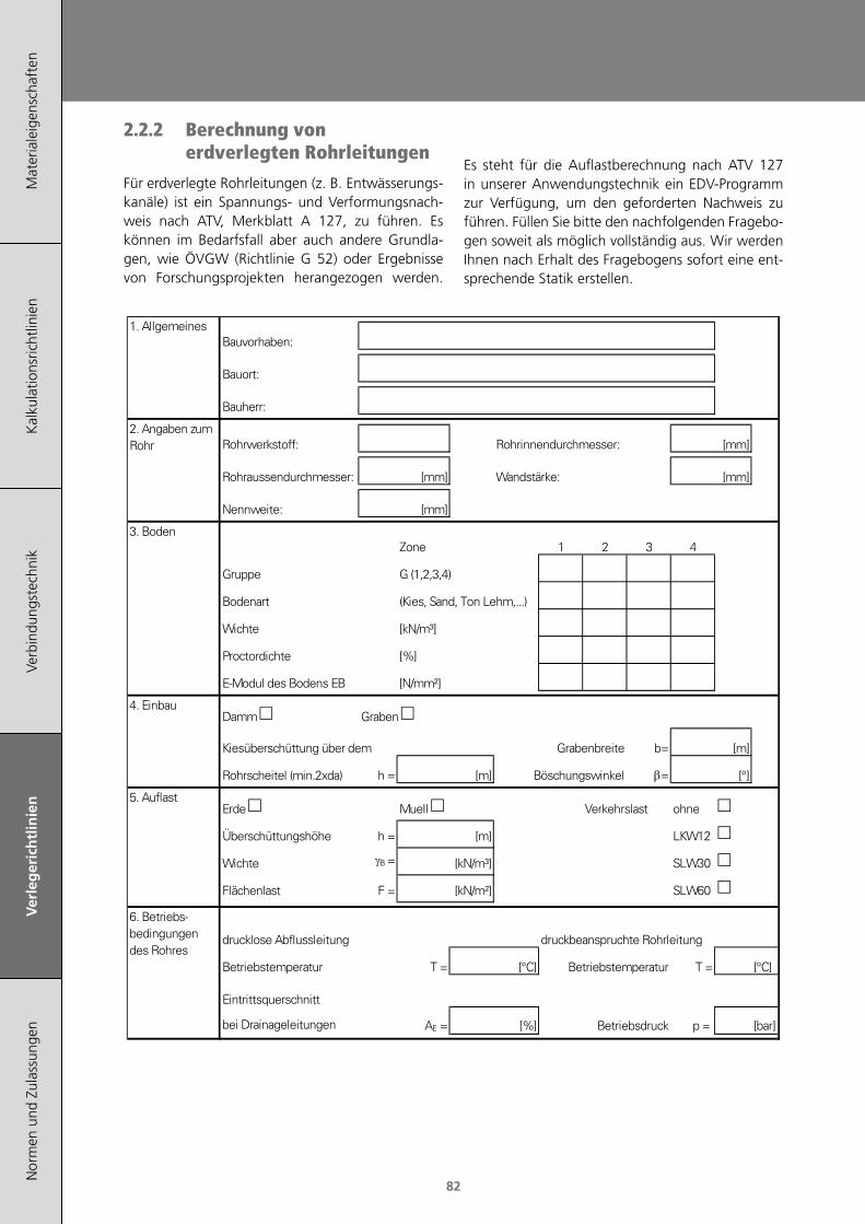
Mat
eria
leig
ensc
haft
enK
alku
latio
nsric
htlin
ien
Verb
indu
ngst
echn
ikV
erle
ger
ich
tlin
ien
Nor
men
und
Zul
assu
ngen
82
2.2.2 Berechnung von erdverlegten Rohrleitungen
Für erdverlegte Rohrleitungen (z. B. Entwässerungs-kanäle) ist ein Spannungs- und Verformungsnach-weis nach ATV, Merkblatt A 127, zu führen. Es können im Bedarfsfall aber auch andere Grundla-gen, wie ÖVGW (Richtlinie G 52) oder Ergebnisse von Forschungsprojekten herangezogen werden.
Es steht für die Auflastberechnung nach ATV 127 in unserer Anwendungstechnik ein EDV-Programm zur Verfügung, um den geforderten Nachweis zu führen. Füllen Sie bitte den nachfolgenden Fragebo-gen soweit als möglich vollständig aus. Wir werden Ihnen nach Erhalt des Fragebogens sofort eine ent-sprechende Statik erstellen.
5757575757
Mat
eria
leig
ensc
haft
enV
erle
geric
htlin
ien
Kal
kula
tions
richt
linie
nV
erbi
ndun
gste
chni
kD
oppe
lrohr
syst
emZu
lass
unge
n un
d N
orm
enK
alku
lati
on
sric
htl
inie
n
Kalkulationsrichtlinien
Berechnung von erdverlegten Rohrleitungen
Für erdverlegte Rohrleitungen (z. B.Entwässerungskanäle) ist ein Spannungs- undVerformungsnachweis nach ATV, Merkblatt A 127,zu führen. Es können im Bedarfsfall aber auchandere Grundlagen, wie ÖVGW (Richtlinie G 52)oder Ergebnisse von Forschungsprojektenherangezogen werden.
Es steht für die Auflastberechnung nach ATV 127in unserer Anwendungstechnik ein EDV-Programmzur Verfügung, um den geforderten Nachweis zuführen.Füllen Sie bitte den nachfolgenden Fragebogensoweit als möglich vollständig aus. Wir werdenIhnen nach Erhalt des Fragebogens sofort eineentsprechende Statik erstellen.
Bauvorhaben:
Bauort:
Bauherr:
Rohrwerkstoff: Rohrinnendurchmesser: [mm]
Rohraussendurchmesser: [mm] Wandstärke: [mm]
Nennweite: [mm]
Zone 1 2 3 4
Gruppe G (1,2,3,4)
Bodenart (Kies, Sand, Ton Lehm,...)
Wichte [kN/m³]
Proctordichte [%]
E-Modul des Bodens EB [N/mm²]
Damm Graben
Kiesüberschüttung über dem Grabenbreite b= [m]
Rohrscheitel (min.2xda) h = [m] Böschungswinkel β= [°]
Erde Muell Verkehrslast ohne
Überschüttungshöhe h = [m] LKW12
Wichte γB = [kN/m³] SLW30
Flächenlast F = [kN/m²] SLW60
drucklose Abflussleitung druckbeanspruchte Rohrleitung
Betriebstemperatur T = [°C] Betriebstemperatur T = [°C]
Eintrittsquerschnitt
bei Drainageleitungen AE = [%] Betriebsdruck p = [bar]
5. Auflast
6. Betriebs-bedingungendes Rohres
1. Allgemeines
2. Angaben zumRohr
3. Boden
4. Einbau

Verlegerichtlinien
Mat
eria
leig
ensc
haft
enK
alku
latio
nsric
htlin
ien
Verb
indu
ngst
echn
ikV
erle
ger
ich
tlin
ien
Nor
men
und
Zul
assu
ngen
83
2.2.2.1 GrabenbreiteDie Grabenbreite muss so bemessen sein, dass ein sicheres Arbeiten und ein fachge-rechter Einbau der Rohrleitung gewährlei-stet werden kann. Baugruben und Gräben von mehr als 0,80 m Breite sind in ausrei-chendem Maße mit Übergängen, z. B. Lauf-brücken oder Laufstegen, zu versehen.
Richtwerte zur Mindestgrabenbreite [mm] in Abhängigkeit des Außendurchmessers (da)
da [mm]
ver‑bauter Graben
unverbauter Graben
β1) > 60° β1) ≤ 60°
≤ 225 da + 400 da + 400
> 225 bis ≤ 355
da + 500 da + 500
da + 400> 355 bis ≤
710da + 700 da + 700
in Abhängigkeit der Grabentiefe
Tiefe [mm] Breite [mm]
< 1000 keine Vorgaben
≥ 1000 bis ≤ 1750 800
> 1750 bis ≤ 4000 900
> 4000 1000
Tabelle D.4: Richtwerte zur Grabenbreite (Quelle: DIN EN 1610).1) Böschungswinkel
2.2.2.2 Bettungsmaterial
Das Bettungsmaterial muss für die entsprechende Rohrleitung geeignet sein, darf also am Rohr keine Korrosion, Beschädigung, chemische oder mechani-sche Beeinträchtigung hervorrufen. Als Einbettung kommt Bettungsmaterial, z.B. ein Sand-Kies-Ge-misch in Frage, das eine ausreichende Verdichtbar-keit aufweist. Damit wird gewährleistet, dass das umliegende verdichtete Erdreich die Kräfte durch In-nendruck und äußere Lasten entsprechend verteilt.
Richtwerte zur mittleren Korngröße in der Lei‑tungszone
DNKorngröße [mm]
rund gebrochen
PE 100 Rohr≤ 200 > 200
0-22 0-40
0-11 0-11
PE 100-RC Rohr
≤ 63 > 63
0-22 0-100
Tabelle D.5: Richtwerte zur mittleren Korngröße in der Lei-tungszone (in Anlehnung an DVGW Arbeitsblatt W 400-2 und ÖVGW/GRIS QS-W 405/1)
Die Überdeckung hat in der Regel mindestens 1 m gemessen vom Rohrscheitel zu betragen. Der Rohr-graben sollte unmittelbar nach der Verlegung ver-füllt werden um Beschädigungen zu vermeiden.
Zur Rohrgrabenverfüllung kann, wenn nicht anders angeordnet (Straßenbau...) grundsätzlich das Aus-hubmaterial wieder eingebracht werden.
Rohrleitungsart Überdeckung [m]
Wasserleitung 0,9¹) - 1,8 m
Gasleitung 0,6¹) - 1,3 m
Abwasserleitung min. 2,0 m
Tabelle D.6: Richtwerte zu Überdeckungshöhen (in Anlehnung an DVGW - Arbeitsblatt W 400-1) ¹) In landwirtschaftlich genutzten Gebieten empfiehlt sich eine Mindestüberdeckungshöhe von 1,2 m.
2.2.3 Verlegung ohne Sandbett
PE 100-RC Rohre und Formteile können zusätzlich zur konventionellen Verlegung im Sandbett auch für nicht konventionelle Verlegetechniken wie die Ver-legung ohne Sandbett oder grabenlose Verlegung verwendet werden.
Sandbettfrei heißt, dass vorher entferntes Aushub-material wieder als Bettungsmaterial und Verfül-lung verwendet werden kann, soweit es sich nach den gängigen Richtlinien (z.B. ÖNORM B2538 und ÖNORM B 5016) verdichten lässt, und die Anfor-derungen für die Korngrößen gemäß „Abweichung vom Regelfall“ der ÖNORM B 2538 beachtet wer-den.
Abbildung D.3: Schematische Darstellung eines Rohrgrabens nach sandbettfreier Verlegung
Richtwerte für die Korngrößen des Bettungsmate-rials:
DN/OD <63 bis 22 mm
DN/OD ≥63 bis 100 mm
Tabelle D.7: Richtwerte für die Korngrößen des Bettungsmateri-als (in Anlehnung an ÖVGW/GRIS PW 405/1)
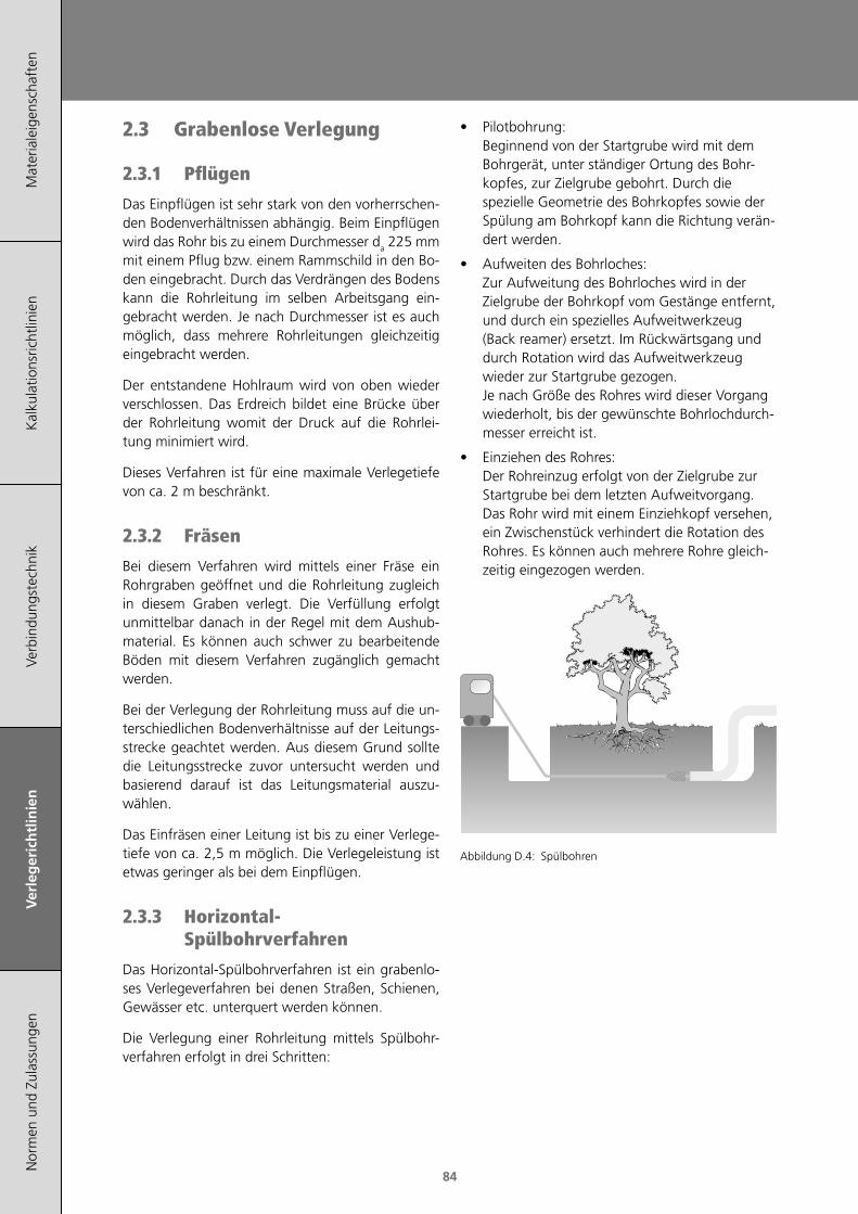
Mat
eria
leig
ensc
haft
enK
alku
latio
nsric
htlin
ien
Verb
indu
ngst
echn
ikV
erle
ger
ich
tlin
ien
Nor
men
und
Zul
assu
ngen
84
2.3 Grabenlose Verlegung
2.3.1 Pflügen
Das Einpflügen ist sehr stark von den vorherrschen-den Bodenverhältnissen abhängig. Beim Einpflügen wird das Rohr bis zu einem Durchmesser da 225 mm mit einem Pflug bzw. einem Rammschild in den Bo-den eingebracht. Durch das Verdrängen des Bodens kann die Rohrleitung im selben Arbeitsgang ein-gebracht werden. Je nach Durchmesser ist es auch möglich, dass mehrere Rohrleitungen gleichzeitig eingebracht werden.
Der entstandene Hohlraum wird von oben wieder verschlossen. Das Erdreich bildet eine Brücke über der Rohrleitung womit der Druck auf die Rohrlei-tung minimiert wird.
Dieses Verfahren ist für eine maximale Verlegetiefe von ca. 2 m beschränkt.
2.3.2 Fräsen
Bei diesem Verfahren wird mittels einer Fräse ein Rohrgraben geöffnet und die Rohrleitung zugleich in diesem Graben verlegt. Die Verfüllung erfolgt unmittelbar danach in der Regel mit dem Aushub-material. Es können auch schwer zu bearbeitende Böden mit diesem Verfahren zugänglich gemacht werden.
Bei der Verlegung der Rohrleitung muss auf die un-terschiedlichen Bodenverhältnisse auf der Leitungs-strecke geachtet werden. Aus diesem Grund sollte die Leitungsstrecke zuvor untersucht werden und basierend darauf ist das Leitungsmaterial auszu-wählen.
Das Einfräsen einer Leitung ist bis zu einer Verlege-tiefe von ca. 2,5 m möglich. Die Verlegeleistung ist etwas geringer als bei dem Einpflügen.
2.3.3 Horizontal-Spülbohrverfahren
Das Horizontal-Spülbohrverfahren ist ein grabenlo-ses Verlegeverfahren bei denen Straßen, Schienen, Gewässer etc. unterquert werden können.
Die Verlegung einer Rohrleitung mittels Spülbohr-verfahren erfolgt in drei Schritten:
• Pilotbohrung: Beginnend von der Startgrube wird mit dem Bohrgerät, unter ständiger Ortung des Bohr-kopfes, zur Zielgrube gebohrt. Durch die spezielle Geometrie des Bohrkopfes sowie der Spülung am Bohrkopf kann die Richtung verän-dert werden.
• Aufweiten des Bohrloches: Zur Aufweitung des Bohrloches wird in der Zielgrube der Bohrkopf vom Gestänge entfernt, und durch ein spezielles Aufweitwerkzeug (Back reamer) ersetzt. Im Rückwärtsgang und durch Rotation wird das Aufweitwerkzeug wieder zur Startgrube gezogen. Je nach Größe des Rohres wird dieser Vorgang wiederholt, bis der gewünschte Bohrlochdurch-messer erreicht ist.
• Einziehen des Rohres: Der Rohreinzug erfolgt von der Zielgrube zur Startgrube bei dem letzten Aufweitvorgang. Das Rohr wird mit einem Einziehkopf versehen, ein Zwischenstück verhindert die Rotation des Rohres. Es können auch mehrere Rohre gleich-zeitig eingezogen werden.
Abbildung D.4: Spülbohren

Verlegerichtlinien
Mat
eria
leig
ensc
haft
enK
alku
latio
nsric
htlin
ien
Verb
indu
ngst
echn
ikV
erle
ger
ich
tlin
ien
Nor
men
und
Zul
assu
ngen
85
2.3.4 Berstlining
Mit dem Berstlining-Verfahren können defekte Rohrleitungen ersetzt werden. Mit dem Berstkör-per wird das bestehende Altrohr zerstört und in das umgebende Erdreich verdrängt. Das Bohrloch wird soweit vergrößert, dass ein neues Rohr mit gleichem oder größeren Durchmesser platz findet, welches im selben Arbeitsschritt eingezogen wird.
Abbildung D.5: Berstlining.
2.4 Freiverlegte RohrleitungenRohre und Leitungen aus thermoplastischem Kunst-stoff unterliegen einer Längenänderung bei Tempe-raturwechsel. Es ergeben sich die folgenden Anfor-derungen an die Befestigung von Rohrleitungsteilen.
2.4.1 Befestigung
Befestigungen bzw. Rohrschellen für PE-Rohrlei-tungssystem sind aus verschiedenen Werkstoffen verfügbar. Bei Rohrschellen aus Stahl ist darauf zu achten, dass diese mit Bändern aus PE oder Elasto-meren ausgeführt sind, um das Kunststoffrohr bei Längenänderungen des Rohres vor Beschädigung zu schützen.
Bei den Befestigungen ist darauf zu achten, dass die Auflageflächen möglichst breit sind um punktför-mige Belastungen zu vermeiden. Der Durchmesser sollte dem Außendurchmesser des Rohres ange-passt sein.
Besonders gut für die Verlegung eignen sich die AGRU Kunststoffrohrschellen bzw. Rohrhalter, wel-che auf die Toleranzen der Kunststoffrohre abge-stimmt sind.
Diese Rohrschellen dienen auch z.B. als Gleitlager bzw. Führungslager bei horizontal verlegten Rohrlei-tungen, nehmen vertikal gerichtete Kräfte auf und verhindern das Ausknicken der Rohrleitung. Hierzu sind die Rohrstützweiten bzw. die maximalen Füh-rungsabstände zur Vermeidung von Ausknicken ein-zuhalten.
Für Rohre kleiner da 63 mm können die Stützweiten-abstände vergrößert werden, wenn die Rohrleitung mit Stahlhalbschalen unterstützt wird.
2.4.2 Festpunkte
Dehnung und Kontraktion der Rohrleitung in Ra-dial- und Axialrichtung dürfen bei oberirdischer Verlegung nicht behindert werden; d.h. Einbau mit radialem Spiel, Schaffung von Kompensations-möglichkeiten, kontrollierte Längenänderung durch sinnvolle Anordnung von Festpunkten.
Armaturen (in bestimmten Anwendungen auch T-Stücke) sollten grundsätzlich als Festpunkt innerhalb einer Leitung ausgebildet werden. Vorteilhaft sind Armaturenkonstruktionen, bei denen die Befesti-gungsvorrichtung im Armaturenkörper integriert ist.
Elektroschweißmuffen in einer Rohrleitung können ebenfalls als Festpunkte verwendet werden.
2.5 ReliningBeim Relining unterscheidet man zwischen zwei Ar-ten:
• Relining mit Ringraum (Slip-Lining)
• Relining ohne Ringraum (Close-Fit-Lining)
2.5.1 Relining mit Ringraum
Bei der Rehabilitation mit Ringraum werden PE-Roh-re eingezogen deren Durchmesser kleiner sind als die der Altleitung. Einerseits kommen Rohrstränge mit mehreren hundert Metern Länge zum Einsatz (z.B. Ringbunde) und andererseits können einzelne Rohre in der Startgrube taktweise verschweißt und in die Altleitung geschoben werden.
Beim Relining mit Ringraum verkleinert sich der Rohrquerschnitt. Teilweise wird die reduzierte Trans-portkapazität aufgrund der guten Oberflächen-beschaffenheit von PE kompensiert. Der gesamte verfügbare Dimensionsbereich von PE-Rohren (20 mm bis 2500 mm) kann für Relining mit Ringraum eingesetzt werden.
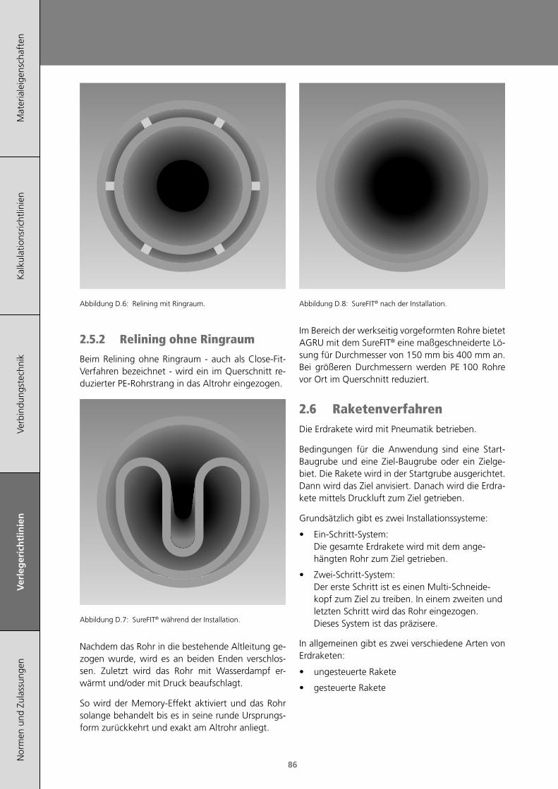
Mat
eria
leig
ensc
haft
enK
alku
latio
nsric
htlin
ien
Verb
indu
ngst
echn
ikV
erle
ger
ich
tlin
ien
Nor
men
und
Zul
assu
ngen
86
Abbildung D.6: Relining mit Ringraum.
2.5.2 Relining ohne Ringraum
Beim Relining ohne Ringraum - auch als Close-Fit-Verfahren bezeichnet - wird ein im Querschnitt re-duzierter PE-Rohrstrang in das Altrohr eingezogen.
Abbildung D.7: SureFIT® während der Installation.
Nachdem das Rohr in die bestehende Altleitung ge-zogen wurde, wird es an beiden Enden verschlos-sen. Zuletzt wird das Rohr mit Wasserdampf er-wärmt und/oder mit Druck beaufschlagt.
So wird der Memory-Effekt aktiviert und das Rohr solange behandelt bis es in seine runde Ursprungs-form zurückkehrt und exakt am Altrohr anliegt.
Abbildung D.8: SureFIT® nach der Installation.
Im Bereich der werkseitig vorgeformten Rohre bietet AGRU mit dem SureFIT® eine maßgeschneiderte Lö-sung für Durchmesser von 150 mm bis 400 mm an. Bei größeren Durchmessern werden PE 100 Rohre vor Ort im Querschnitt reduziert.
2.6 RaketenverfahrenDie Erdrakete wird mit Pneumatik betrieben.
Bedingungen für die Anwendung sind eine Start-Baugrube und eine Ziel-Baugrube oder ein Zielge-biet. Die Rakete wird in der Startgrube ausgerichtet. Dann wird das Ziel anvisiert. Danach wird die Erdra-kete mittels Druckluft zum Ziel getrieben.
Grundsätzlich gibt es zwei Installationssysteme:
• Ein-Schritt-System: Die gesamte Erdrakete wird mit dem ange-hängten Rohr zum Ziel getrieben.
• Zwei-Schritt-System: Der erste Schritt ist es einen Multi-Schneide-kopf zum Ziel zu treiben. In einem zweiten und letzten Schritt wird das Rohr eingezogen. Dieses System ist das präzisere.
In allgemeinen gibt es zwei verschiedene Arten von Erdraketen:
• ungesteuerte Rakete
• gesteuerte Rakete
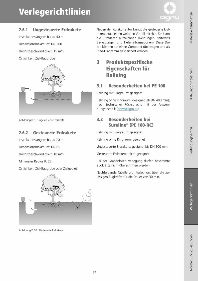
Verlegerichtlinien
Mat
eria
leig
ensc
haft
enK
alku
latio
nsric
htlin
ien
Verb
indu
ngst
echn
ikV
erle
ger
ich
tlin
ien
Nor
men
und
Zul
assu
ngen
87
2.6.1 Ungesteuerte Erdrakete
Installationslängen: bis zu 40 m
Dimensionsmaximum: DN 200
Höchstgeschwindigkeit: 15 m/h
Örtlichkeit: Ziel-Baugrube
Abbildung D.9: Ungesteuerte Erdrakete.
2.6.2 Gesteuerte Erdrakete
Installationslängen: bis zu 70 m
Dimensionsmaximum: DN 65
Höchstgeschwindigkeit: 10 m/h
Minimaler Radius R: 27 m
Örtlichkeit: Ziel-Baugrube oder Zielgebiet
R
Abbildung D.10: Gesteuerte Erdrakete.
Neben der Kurskorrektur bringt die gesteuerte Erd-rakete noch einen weiteren Vorteil mit sich. Sie kann die Kursdaten aufzeichnen (Neigungen, seitwärts Bewegungen und Tiefeninformationen). Diese Da-ten können auf einen Computer übertragen und als Pfad-Diagramm gespeichert werden.
3 Produktspezifische Eigenschaften für Relining
3.1 Besonderheiten bei PE 100Relining mit Ringraum: geeignet
Relining ohne Ringraum: geeignet (ab DN 400 mm); nach technischer Rücksprache mit der Anwen-dungstechnik ([email protected])
3.2 Besonderheiten bei Sureline® (PE 100-RC)
Relining mit Ringraum: geeignet
Relining ohne Ringraum: geeignet
Ungesteuerte Erdrakete: geeignet bis DN 200 mm
Gesteuerte Erdrakete: nicht geeignet
Bei der Grabenlosen Verlegung dürfen bestimmte Zugkräfte nicht überschritten werden.
Nachfolgende Tabelle gibt Aufschluss über die zu-lässigen Zugkräfte für die Dauer von 30 min.

Mat
eria
leig
ensc
haft
enK
alku
latio
nsric
htlin
ien
Verb
indu
ngst
echn
ikV
erle
ger
ich
tlin
ien
Nor
men
und
Zul
assu
ngen
88
da [mm]Maximal zulässige Zugkräfte [10 kN/
mm²]
SDR 17 SDR 11
20 °C 40 °C 20 °C 40 °C
63 - - 10 7,2
75 9,5 6,6 15 10
90 14 9,5 21 15
110 20 14 31 22
125 26 18 41 28
140 33 23 51 36
160 43 30 66 47
180 55 38 84 59
200 67 47 104 73
225 85 60 131 92
250 105 74 162 114
280 132 92 204 142
315 167 117 258 180
355 212 149 327 229
400 269 189 415 291
450 341 239 526 368
500 421 295 648 454
560 528 370 814 570
630 668 468 1030 721
710 849 594 1309 916
Tabelle D.8: Zugkräfte für Sureline®-Rohre (Quelle: DVGW GW 320-1).
Bei einer Einziehdauer von >30 min sind die Werte um 10 % abzumindern.
Bei einer Einziehdauer von >20 h sind die Werte um 25 % abzumindern.
Durch die hohe Elastizität und Flexibilität der Sureline®-Rohre (PE 100-RC Rohre) können Rich-tungsänderungen bei der Verlegung ohne der Ver-wendung von Formteilen realisiert werden. Dabei sind die genannten Mindestbiegeradien (siehe Ka-pitel 2.1) zu berücksichtigen.
3.3 Besonderheiten bei SureFIT® (PE 100)
Relining mit Ringraum: nicht geeignet
Relining ohne Ringraum: geeignet (von Dim150 mm bis DN 400 mm)
3.4 Besonderheiten bei SurePEX (PE-Xa)
Relining mit Ringraum: geeignet
Relining ohne Ringraum: geeignet
Ungesteuerte Erdrakete: geeignet
Gesteuerte Erdrakete: geeignet
Rohre aus PE-Xa lassen sich aufgrund des geringen E-Moduls leichter verarbeiten als PE 100 Rohre. Niedrige Temperaturen um den Gefrierpunkt haben eine Abnahme der Flexibilität des Rohrmaterials zur Folge. Aus diesem Grund ist es zu empfehlen, die Ringbunde in einer geheizten Halle oder in einem geheizten Zelt bis kurz vor der Verlegung zwischen-zulagern um ein einfacheres Abwickeln des Ring-bundes bzw. eine einfachere Verlegung zu gewähr-leisten.
Alternativ können die Rohre auch durch Durchleiten von warmer Luft oder Dampf erwärmt werden.
Das Abquetschen von PE-Xa Druckrohrsystemen ist gemäß ÖVGW und DVGW Regelwerk zulässig. Die Quetschstelle muss von der nächsten Rohrverbin-dung / Verbindungsstelle einen Mindestabstand von 5 × da aufweisen.

Verlegerichtlinien
Mat
eria
leig
ensc
haft
enK
alku
latio
nsric
htlin
ien
Verb
indu
ngst
echn
ikV
erle
ger
ich
tlin
ien
Nor
men
und
Zul
assu
ngen
89
4 Spanende BearbeitungTrennen
t Freiwinkel αSpanwinkel γTeilung tSchnittgeschwindigkeit ν
[°][°][mm][m/min]
20 - 302 - 53 - 8500
Bandsägen sind geeignet zum Schneiden von Rohren, Blöcken, dicken Platten und für Rund-schnitte.
Trennen
α
γ
Freiwinkel αSpanwinkel γTeilung tSchnittgeschwindigkeit ν
[°][°][mm][m/min]
20 - 306 - 103 - 82000
Kreissägen sind geeignet zum Schneiden von Rohren, Blöcken, Platten. Hartmetall-Sägen haben eine wesentlich längere Lebensdauer.
Drehen
a
λ
γ
α
Freiwinkel αSpanwinkel γEinstellwinkel λSchnittgeschwindigkeit νVorschub fSpantiefe a
[°][°][°][m/min][mm/min-1][mm]
6 - 100 - 545 - 60250 - 5000,1 - 0,5>0,5
Der Spitzenradius (r) sollte min-destens 0,5 mm betragen. Hohe Oberflächengüte wird durch Drehmeißel mit Breitschlicht-schneide erreicht. Abstechen: Drehmeißel messer-artig anschleifen.
Fräsen
α
γ
Freiwinkel αSpanwinkel γSchnittgeschwindigkeit νVorschub f
[°][°][m/min][mm/Zahn]
10 - 205 - 15250 - 5000,5
Hohe Oberflächengüte durch Fräser mit weniger Schneidemes-ser - dadurch höhere Schnittleis-tung.
Bohren
ϕ
α
γ
Freiwinkel αSpanwinkel γSpitzenwinkel φSchnittgeschwindigkeit νVorschub fDrallwinkel γx
[°][°][°][m/min][mm/min-1][°]
5 - 1510 - 2060 - 9050 - 1500,1 - 0,312 - 16
Für Bohrungen von 40 mm - 150 mm Durchmesser sollten Hohlbohrer eingesetzt werden, für alle Löcher <40 mm Durch-messer normale Schnellschnitt-Stahlbohrer.
Tabelle D.9: Parameterrichtwerte für spanende Bearbeitung.
Die Schnittgeschwindigkeit, den Vorschub und die Schneidgeometrie sind so zu wählen, dass die ent-stehende Wärme zum größten Teil durch den Span abgeführt wird (eine zu hohe Erwärmung kann zum Anschmelzen bzw. zur Verfärbung der bearbeiteten Oberfläche führen).
Als Bearbeitungsmaschinen können alle üblichen Metall- und Holzbearbeitungsmaschinen verwendet werden.
Achtung: die Verwendung von Silikonfetten oder anderen Schmierstoffen, die das Schweißergebnis negativ beeinflussen können, ist nicht gestattet.

Mat
eria
leig
ensc
haft
enK
alku
latio
nsric
htlin
ien
Verb
indu
ngst
echn
ikV
erle
ger
ich
tlin
ien
Nor
men
und
Zul
assu
ngen
90

Normen und Zulassungen
Mat
eria
leig
ensc
haft
enK
alku
latio
nsric
htlin
ien
Verle
geric
htlin
ien
Verb
indu
ngst
echn
ikN
orm
en u
nd
Zu
lass
un
gen
91
1 Normen 93
2 Zulassungen / Fremdüberwachung 93

Mat
eria
leig
ensc
haft
enK
alku
latio
nsric
htlin
ien
Verle
geric
htlin
ien
Verb
indu
ngst
echn
ikN
orm
en u
nd
Zu
lass
un
gen
92

Normen und Zulassungen
Mat
eria
leig
ensc
haft
enK
alku
latio
nsric
htlin
ien
Verle
geric
htlin
ien
Verb
indu
ngst
echn
ikN
orm
en u
nd
Zu
lass
un
gen
93
1 NormenAGRULINE-Rohre und Formstücke werden aus ge-normten Formmassen hergestellt und nach ein-schlägigen internationalen Normen und Richtlinien produziert.
Nachstehend ein Auszug der wichtigsten Normen /Richtlinien für PE:
• ÖNORM B 5014-1 Sensorische und chemische Anforderungen und Prüfung von Werkstoffen im Trinkwasserbereich - Teil 1: Organische Werkstoffe.
• DIN 8074 Rohre aus Polyethylen (PE) - PE 63, PE 80, PE 100, PE-HD - Maße.
• DIN 8075 Rohre aus Polyethylen (PE) - PE 63, PE 80, PE 100, PE-HD - Allgemeine Güteanforderun-gen, Prüfungen.
• DIN 16963 (Teil 1 - Teil 15) Rohrverbindungen und Rohrleitungsteile für Druckrohrleitungen aus Polyethylen hoher Dich-te (HDPE), Typ 1 und 2.
• EN 1555 (Teil 1 - Teil 7) Kunststoff-Rohrleitungssysteme für die Gasver-sorgung - Polyethylen (PE).
• EN 12201 (Teil 1 - Teil 7) Kunststoff-Rohrleitungssysteme für die Wasser-versorgung - Polyethylen (PE).
• ISO 1872-1 Plastics - Polyethylene (PE) moulding and extru-sion materials.
• ISO 4065 Thermoplastics pipes - Universal wall thickness table.
• ISO 4427 (Teil 1 - Teil 5) Plastics piping systems - Polyethylene (PE) pipes and fittings for water supply.
• ISO 4437 (Teil 1 - Teil 5) Buried polyethylene (PE) pipes for the supply of gaseous fuels - Metric series - Specifications.
• ÖVGW QS-G 392 (Teil 1-4) Gasrohrsysteme aus Polyethylen PE 80, PE 100 und PE 100-RC
• ÖVGW PW 405 Teil 1 Rohrleitungssysteme aus Polyethylen PE 100-RC für nicht konventionelle Verlegetechniken in der Trinkwasserversorgung
• ÖVGW PW 406 (Teil 1 -3) Rohrleitungssysteme aus Polyethylen (PE 40, PE 80 und PE 100) für die Trinkwasserversorgung
• GRIS GV 19 Spezielle Gütevorschrift für Kanalrohre und Formstücke aus Polyethylen (PE) für den Sied-lungswasserbau
• GRIS GV 20 Spezielle Gütevorschrift für Kanal-Druckrohre und Formstücke aus Polyethylen PE 100-RC für nicht konventionelle Verlegetechniken im Siedlungswasserbau
• PAS 1075 Rohre aus Polyethylen für alternative Verlege-techniken
• DVGW W 400/1 Technische Regel Wasserverteilungsanlagen (TRWV) - Teil 1: Planung
2 Zulassungen / Fremdüberwachung
Die regelmäßige Fremdüberwachung der Produk-te erfolgt durch staatlich anerkannte Prüfstellen auf Basis von Überwachungsverträgen gemäß den Normen und Prüfbescheiden für die jeweiligen Pro-duktgruppen. Derzeit sind mit der Fremdüberwa-chung für die Produktion beauftragt:
• IIP Milano
• MPA Darmstadt
• TGM Wien
• TÜV Süd
• Certigaz

Mat
eria
leig
ensc
haft
enK
alku
latio
nsric
htlin
ien
Verle
geric
htlin
ien
Verb
indu
ngst
echn
ikN
orm
en u
nd
Zu
lass
un
gen
94
Der hohe Qualitätsstandard unserer Produkte ist durch eine Reihe von Zulassungen dokumentiert und in folgenden Ländern für die Gas- und Wasser-versorgung zugelassen:
Land Zulassung Gas Wasser Abwasser
Algerien Sonelgaz ×
Australien Watermark ×
BelgienBELGAQUA ×
Electrabel ×
DeutschlandDVGW × ×
Dibt × ×
EuropaEN 12201 × ×
EN 1555 ×
Frankreich Gaz de France ×
Großbritannien & Nordirland WRAS ×
Italien IIP - UNI × ×
Neuseeland Watermark ×
ÖsterreichÖVGW × ×
GRIS ×
Polen Install × ×
RusslandDIN Gost TÜV × ×
GasCert ×
Schweiz SVGW × ×
Spanien GAS NATURAL ×
Tabelle E.1: Übersicht Zulassungen.
FM-Zulassung 175 und 200 psi für PE Rohre und diver-se Formteile (Dim 63 - 500mm) nach FM Klasse 1613 „Plastic pipes and fittings for underground fire pro-tection service“.
DNV Zulassung für die Verwendung von Rohren/Fittingen aus PE100 / PE100-RC in Systemen für Wasser und Seewasser.

Table of contents
95
Mat
eria
l pro
pert
ies
Cal
cula
tion
guid
eC
onne
ctio
n te
chno
logy
Inst
alla
tion
guid
eSt
anda
rds
and
appr
oval
s
A Material properties 97
B Calculation guide 111
C Connection technology 131
D Installation guide 145
E Standards and approvals 175

96
Mat
eria
l pro
pert
ies
Cal
cula
tion
guid
eC
onne
ctio
n te
chno
logy
Inst
alla
tion
guid
eSt
anda
rds
and
appr
oval
s

97
Material properties
Mat
eria
l pro
per
ties
Cal
cula
tion
guid
eC
onne
ctio
n te
chno
logy
Inst
alla
tion
guid
eSt
anda
rds
and
appr
oval
s
97
1 General properties 99
2 Material-specific properties 101
3 Comparison pressure ratings 107
4 Resistance of polyethylene 108

98
Mat
eria
l pro
per
ties
Cal
cula
tion
guid
eC
onne
ctio
n te
chno
logy
Inst
alla
tion
guid
eSt
anda
rds
and
appr
oval
s

99
Material properties
Mat
eria
l pro
per
ties
Cal
cula
tion
guid
eC
onne
ctio
n te
chno
logy
Inst
alla
tion
guid
eSt
anda
rds
and
appr
oval
s
1 General properties
1.1 Polyethylene (PE)As a result of the continuous development of PE re-sins, the efficiency of PE pipes and fittings has been improved significantly. Due to that fact new inter-national standards (ISO 9080, EN 1555, EN 12201) were introduced, which lead to higher permissible operating pressures.
Polyethylene for pipes and fittings is no longer clas-sified by its density (e.g. PE-LD, PE-MD, PE-HD) but it is now divided into MRS-classes (MRS = minimum required strength).
−
HH
CC
HH
||
||
n
Figure A.1: Chemical structure of polyethylene.
1.1.1 Advantages of PE• High flexibility
• Weldable
• Low weight
• Convenient transportation (e.g. coiled bundles)
• UV resistance (with carbon black)
• Excellent chemical resistance
• Excellent weather-resistance
• Excellent radiation resistance
• Excellent abrasion resistance
• Minimal deposits and no ingrowth possible due to lower frictional resistance
• Lower pressure losses in comparison to e.g. metals
• Resistant against pressure surges (up to 200% of the MOP)
• Application at lower temperatures
• Resistant to rodents
• Low microbial growth
• Physiologically safe
1.2 PE 100 polyethylene typeThese materials are also known as polyethylene types of the third generation (Minimum Required Strength MRS=10 MPa).
PE 100 materials are advanced type PE-HD materials which show an altered, bimodal molecular weight distribution due to a modified polymerisation pro-cess. Because of that PE 100 types have a higher density and improved mechanical properties such as stiffness or hardness. The creep strength and the resistance against rapid crack propagation are incre-ased significantly.
Therefore, PE 100 is suitable for the production of large diameter pressure pipes. These can achieve the same pressure rating with smaller wall thickness compared to conventional pressure pipes made of PE-HD (PE80).
1.3 PE 100-RC polyethylene type
Regarding the pressure resistance and the processa-bility there are no differences between PE 100-RC materials and PE 100 materials.
The primary difference, compared to the standard PE 100 materials, is the high resistance against the slow crack growth. This property allows a safe sand-bed-free installation as well as a use of alternative installation technologies for underground piping systems.
During a sandbed-free installation the excavated material (soil, gravel, ballast) can be reused for the filling if it is compressible acc. to the current stan-dards.
Guideline for the grain size of the excavated materi-al (source: ÖVGW/GRIS PW 405/1):
DIM OD <63 mm up to 22 mm grain size DIM OD >63 mm up to 100 mm grain size
PE 100-RC therefore provides extended protection against:
• point loads,
• crack initiation,
• slow crack growth (SCG).
100
Mat
eria
l pro
per
ties
Cal
cula
tion
guid
eC
onne
ctio
n te
chno
logy
Inst
alla
tion
guid
eSt
anda
rds
and
appr
oval
s
1.4 PE-Xa cross-linked polyethylene type
PE-Xa resin is produced by cross-linking the poly-ethylene with peroxide at high pressures. During the process the individual polyethylene molecules form a three-dimensional network.
The cross-linking process ensures a uniform cross-linking throughout the entire cross section of the pipe, even for thick-walled pipes.
After the cross-linking process the PE-Xa material cannot be re-melted and is referred to as a thermo-elastic material. It combines the positive properties of the thermoplastic and elastomeric materials.
PE-Xa pipes have following properties:
• Notch resistance
• Point loads resistance
• Stress cracking resistance
• High resistance against slow crack growth
• High resistance against abrasion
• High impact strength at extremely low tempe-ratures
• High flexibility at low temperatures
• Suitable for operating temperatures up to 95 °C
• High memory-effect
These material properties lead to additional practical advantages during the installation:
• Suitable for trenchless installation and rehabili-tation (pipes on coils):
• Especially for areas with high soil settlement
• Very high operating safety
Because of these properties PE-Xa pipes can be ins-talled in areas with a maximum safety requirements, such as underground installation of natural gas or water pipelines.
1.4.1 Resistance to slow crack growth
Point loads on the outside of the pipe (e.g. caused by stones) can lead to stress concentrations and elongations on the inside of the pipe.
These could lead to tiny capillary cracks within the structure (stress corrosion cracking), which causes a premature failure of non-cross-linked PE pipes.
Compared to normal pipe a PE-Xa pipe has a much higher resistance against the crack initiation.There-fore PE-Xa pipes can be installed without a sand bed.
1.4.2 Notch behaviour
During the underground installation and possibly during the operation of the system, notches might occur in the pipe surface.
PE-Xa has a substantially higher resistance to scrat-ches and slow crack growth than pipes, made of standard PE-HD.
Long-term pressure tests have proven that the mi-nimum test duration according to DIN 16892 are outperformed even with a notch up to 20 % of the nominal wall thickness.
PE-Xa pipes are especially suitable for trenchless installation methods where damages of the pipe surface cannot be avoided during the installation process.
1.4.3 Reduced Rapid crack propagation (RCP)
Rapid crack propagation is the tendency of plastics pipes to develop brittle cracks under high pressu-res, compressed media and low temperatures.These cracks propagate in the pipe wall at high speed into long cracks.
Even at temperatures of -50 °C and 16 bar pressu-re no rapid crack propagation was observed for the pipes made of PE-Xa.

101
Material properties
Mat
eria
l pro
per
ties
Cal
cula
tion
guid
eC
onne
ctio
n te
chno
logy
Inst
alla
tion
guid
eSt
anda
rds
and
appr
oval
s
2 Material-specific properties
2.1 PE 100 and PE 100-RC
2.1.1 Material properties
The values mentioned are guidelines for the particular material.
Properties Standard Unit PE 100 PE 100‑RC
mec
han
ical
/ p
hys
ical
MRS Classification ISO 9080 N/mm² 10 10
Specific density at 23 °C ISO 1183 g/cm³ 0.96 2) 0.96 2)
Melt flow rate (MFR 190/5)ISO 1133-1
g/10min ~0.3 1) ~0.3 1)
MFI range T003 T003
Tensile stress at yield ISO 527 MPa ≥23 ≥23
Elongation at yield ISO 527 % ≥9 ≥9
Elongation at break ISO 527 % >350 2) ≥350 2)
Impact strength unnotched (at -30 °C) ISO 179 kJ/m² no break no break
Impact strength notched (at +23 °C) ISO 179 kJ/m² ≥13 3) ≥13 3)
Impact strength notched (at -30 °C) ISO 179 kJ/m² 10 10
Shore-D hardness (3 sec) ISO 868 1 ~60 ~60
Flexural strength (3.5 % flexural stress) ISO 178 MPa ≥21 ≥21
Young‘s Modulus ISO 527 MPa ≥1000 ≥1000
Stress cracking resistance (FNCT)ISO 16770EN 12814-3
h ≥300 3) ≥8760 3)
ther
mal
Heat deflection temperature HDT/B ISO 75 °C 75 75
Linear coefficient of thermal expansion DIN 53752 K-1 × 10⁻⁴ 1.8 4) 1.8 4)
Thermal conductivity (at 20 °C) DIN 52612 W / (m×K) ~0.4 ~0.4
FlammabilityUL 94 - 94-HB 94-HB
DIN 4102 - B2 B2
Application temperature - °C -40 to +60 *
elec
tric
Volume resistivity VDE 0303 Ω × cm >1016 >1016
Surface resistivity VDE 0303 Ω >1013 >1013
Dielectric coefficient at1 MHz DIN 53483 - 2.3 2.3
Electric strength VDE 0303 kV/mm 70 70
gen
eral Physiologically inert EEC 90/128 - yes yes
UV stabiliser - - carbon black
Color - - black black
Table A.1: Specific material properties of PE 100 and PE 100-RC
Guidelines from:
1) DVS 2207-1 2) EN 12201 3) DVS 2205-1 suppl.1 4) DVS 2210-1
* depending on the application area and operating time (see chapter 2.1.3)

102
Mat
eria
l pro
per
ties
Cal
cula
tion
guid
eC
onne
ctio
n te
chno
logy
Inst
alla
tion
guid
eSt
anda
rds
and
appr
oval
s
2.1.2 Hydrostatic long-term strength
1 yea
r
10 ye
ars
25 ye
ars
50 ye
ars
100 y
ears
1 10
Time to failure, t [h]
1
10
Hoo
p st
ress
, σ [N
/mm
²]
2
3
4
5
6
7
89
20
30
40
50
102 103 104 105 106
10 °C
20 °C
30 °C
40 °C
50 °C
60 °C
70 °C
80 °C
Figure A.2: Hydrostatic long-term strength (hoop stress graph) for PE 100 and PE 100-RC (Source: DVS 2205-1 suppl. 1, EN ISO 15494:2013)
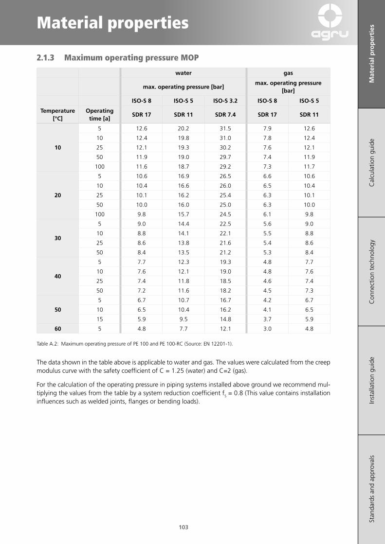
103
Material properties
Mat
eria
l pro
per
ties
Cal
cula
tion
guid
eC
onne
ctio
n te
chno
logy
Inst
alla
tion
guid
eSt
anda
rds
and
appr
oval
s
2.1.3 Maximum operating pressure MOP
water gas
max. operating pressure [bar]max. operating pressure
[bar]
ISO‑S 8 ISO‑S 5 ISO‑S 3.2 ISO‑S 8 ISO‑S 5
Temperature [°C]
Operating time [a]
SDR 17 SDR 11 SDR 7.4 SDR 17 SDR 11
10
5 12.6 20.2 31.5 7.9 12.6
10 12.4 19.8 31.0 7.8 12.4
25 12.1 19.3 30.2 7.6 12.1
50 11.9 19.0 29.7 7.4 11.9
100 11.6 18.7 29.2 7.3 11.7
20
5 10.6 16.9 26.5 6.6 10.6
10 10.4 16.6 26.0 6.5 10.4
25 10.1 16.2 25.4 6.3 10.1
50 10.0 16.0 25.0 6.3 10.0
100 9.8 15.7 24.5 6.1 9.8
30
5 9.0 14.4 22.5 5.6 9.0
10 8.8 14.1 22.1 5.5 8.8
25 8.6 13.8 21.6 5.4 8.6
50 8.4 13.5 21.2 5.3 8.4
40
5 7.7 12.3 19.3 4.8 7.7
10 7.6 12.1 19.0 4.8 7.6
25 7.4 11.8 18.5 4.6 7.4
50 7.2 11.6 18.2 4.5 7.3
50
5 6.7 10.7 16.7 4.2 6.7
10 6.5 10.4 16.2 4.1 6.5
15 5.9 9.5 14.8 3.7 5.9
60 5 4.8 7.7 12.1 3.0 4.8
Table A.2: Maximum operating pressure of PE 100 and PE 100-RC (Source: EN 12201-1).
The data shown in the table above is applicable to water and gas. The values were calculated from the creep modulus curve with the safety coefficient of C = 1.25 (water) and C=2 (gas).
For the calculation of the operating pressure in piping systems installed above ground we recommend mul-tiplying the values from the table by a system reduction coefficient fS = 0.8 (This value contains installation influences such as welded joints, flanges or bending loads).
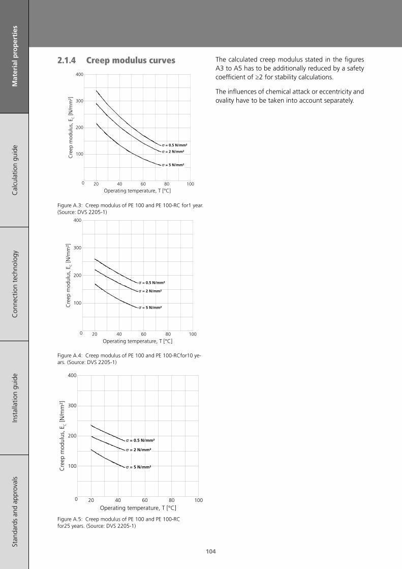
104
Mat
eria
l pro
per
ties
Cal
cula
tion
guid
eC
onne
ctio
n te
chno
logy
Inst
alla
tion
guid
eSt
anda
rds
and
appr
oval
s
2.1.4 Creep modulus curves
Figure A.3: Creep modulus of PE 100 and PE 100-RC for1 year. (Source: DVS 2205-1)
Figure A.4: Creep modulus of PE 100 and PE 100-RCfor10 ye-ars. (Source: DVS 2205-1)
Figure A.5: Creep modulus of PE 100 and PE 100-RC for25 years. (Source: DVS 2205-1)
The calculated creep modulus stated in the figures A3 to A5 has to be additionally reduced by a safety coefficient of ≥2 for stability calculations.
The influences of chemical attack or eccentricity and ovality have to be taken into account separately.
Operating temperature, T [°C]
0
100
200
300
400
20 40 60 80 100
σ = 0.5 N/mm²
σ = 2 N/mm²
σ = 5 N/mm²Cre
ep m
odul
us, E
C [N
/mm
²]
Operating temperature, T [°C]
0
100
200
300
400
20 40 60 80 100
σ = 0.5 N/mm²
σ = 2 N/mm²
σ = 5 N/mm²Cre
ep m
odul
us, E
C [N
/mm
²]
Operating temperature, T [°C]
0
100
200
300
400
20 40 60 80 100
σ = 0.5 N/mm²
σ = 2 N/mm²
σ = 5 N/mm²
Cre
ep m
odul
us, E
C [N
/mm
²]
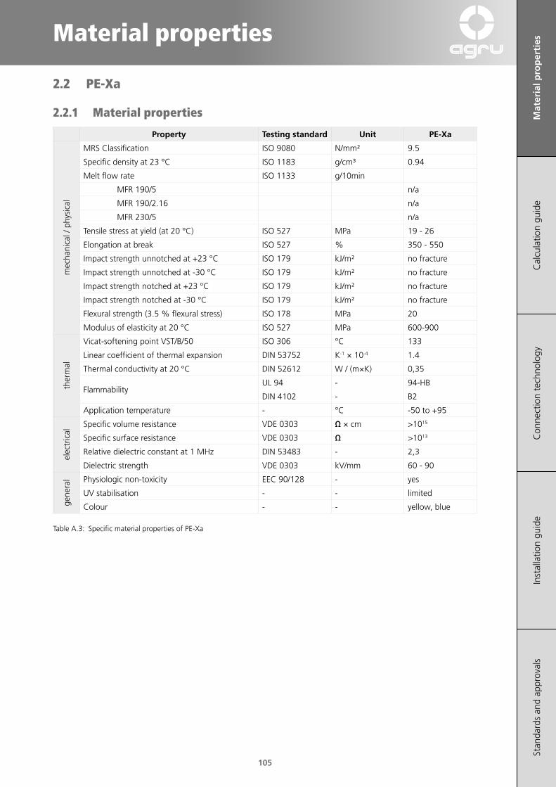
105
Material properties
Mat
eria
l pro
per
ties
Cal
cula
tion
guid
eC
onne
ctio
n te
chno
logy
Inst
alla
tion
guid
eSt
anda
rds
and
appr
oval
s
2.2 PE-Xa
2.2.1 Material properties
Property Testing standard Unit PE‑Xa
mec
hani
cal /
phy
sica
l
MRS Classification ISO 9080 N/mm² 9.5
Specific density at 23 °C ISO 1183 g/cm³ 0.94
Melt flow rate ISO 1133 g/10min
MFR 190/5 n/a
MFR 190/2.16 n/a
MFR 230/5 n/a
Tensile stress at yield (at 20 °C) ISO 527 MPa 19 - 26
Elongation at break ISO 527 % 350 - 550
Impact strength unnotched at +23 °C ISO 179 kJ/m² no fracture
Impact strength unnotched at -30 °C ISO 179 kJ/m² no fracture
Impact strength notched at +23 °C ISO 179 kJ/m² no fracture
Impact strength notched at -30 °C ISO 179 kJ/m² no fracture
Flexural strength (3.5 % flexural stress) ISO 178 MPa 20
Modulus of elasticity at 20 °C ISO 527 MPa 600-900
ther
mal
Vicat-softening point VST/B/50 ISO 306 °C 133
Linear coefficient of thermal expansion DIN 53752 K-1 × 10⁻⁴ 1.4
Thermal conductivity at 20 °C DIN 52612 W / (m×K) 0,35
FlammabilityUL 94 - 94-HB
DIN 4102 - B2
Application temperature - °C -50 to +95
elec
tric
al
Specific volume resistance VDE 0303 Ω × cm >1015
Specific surface resistance VDE 0303 Ω >1013
Relative dielectric constant at 1 MHz DIN 53483 - 2,3
Dielectric strength VDE 0303 kV/mm 60 - 90
gene
ral Physiologic non-toxicity EEC 90/128 - yes
UV stabilisation - - limited
Colour - - yellow, blue
Table A.3: Specific material properties of PE-Xa

106
Mat
eria
l pro
per
ties
Cal
cula
tion
guid
eC
onne
ctio
n te
chno
logy
Inst
alla
tion
guid
eSt
anda
rds
and
appr
oval
s
2.2.2 Hydrostatic long-term strength
1 yea
r
10 ye
ars
25 ye
ars
50 ye
ars
100 y
ears
1 10
Time to failure, t [h]
1
10
Hoo
p st
ress
, σ [N
/mm
²]
2
3
4
5
6
7
89
20
30
40
50
102 103 104 105 106
10 °C
20 °C
30 °C
40 °C
50 °C60 °C
70 °C80 °C
90 °C95 °C
110 °C
Figure A.6: Hydrostatic long-term strength (hoop stress graph) for PE-Xa (Source: DIN 16893).

107
Material properties
Mat
eria
l pro
per
ties
Cal
cula
tion
guid
eC
onne
ctio
n te
chno
logy
Inst
alla
tion
guid
eSt
anda
rds
and
appr
oval
s
2.2.3 Maximum operating pressure MOP
max. operating pressu‑re [bar]
Water Gas
Tempera‑ture [°C]
Operating time [a]
SDR 11 / ISO‑S 5
10
1 17.9 11.25 17.5 10.9
10 17.4 10.925 17.2 10.850 17.1 10.7
100 17.0 10.6
20
1 15.8 9.95 15.5 9.7
10 15.4 9.625 15.2 9.550 15.1 9.4
100 15.0 9.4
30
1 14.0 8.85 13.8 8.6
10 13.7 8.625 13.5 8.450 13.4 8.4
100 13.3 8.3
40
1 12.5 7.85 12.2 7.6
10 12.1 7.625 12.0 7.550 11.9 7.4
100 11.8 7.4
50
1 11.1 6.95 10.9 6.8
10 10.8 6.825 10.7 6.750 10.6 6.6
100 10.5 6.6
60
1 9.9 6.25 9.7 6.1
10 9.7 6.125 9.5 5.950 9.5 5.9
70
1 8.9 5.65 8.7 5.4
10 8.6 5.425 8.5 5.350 8.5 5.3
80
1 8.0 5.05 7.8 4.9
10 7.7 4.825 7.6 4.8
901 7.2 4.55 7.0 4.4
10 6.9 4.3
95 1 6.8 4.35 6.6 4.1
Table A.4: Maximum operating pressure of PE-Xa (Source: DIN 16893).
The data shown in the table above is applicable to water and gas. The values were calculated from the creep modulus curve with the safety coefficient of C = 1.25 (water) and C=2 (gas).
3 Comparison pressure ratings
Table A.5 shows the comparison of the SDR, S series and PN pressure ratings (valid for 20 °C, 50 years durability and C = 1.25 (water)).
SDR S
PN‑pressure rating (water)
PE100 / PE100‑RC
PE‑Xa PE 80
41 20 4 - 3,2
33 16 5 - 4
26 12,5 6,3 - 5
17 8 10 - 7,5
11 5 16 12,5 8
9 4 20 - 12,5
7,4 3,2 25 20 20
Table A.5: Comparison pressure rating (Source: EN 12201-2, DVGW G400-1, DVGW G472).

108
Mat
eria
l pro
per
ties
Cal
cula
tion
guid
eC
onne
ctio
n te
chno
logy
Inst
alla
tion
guid
eSt
anda
rds
and
appr
oval
s
4 Resistance of polyethylene
4.1 Physical resistance
4.1.1 Physiological safety
Polyethylene complies with the relevant food law requirements (according to ÖNORM B 5014 Part 1, BGA, KTW guidelines).
PE pipes and fittings are verified regarding drinking water suitability and registered according to DVGW guideline W270.
4.1.2 Behaviour at radiation exposure
Pipes made of polyethylene may be used in the field of high energy radiation. PE pipes are well establis-hed as drainages for radioactive sewage from labo-ratories as well as cooling water systems for nuclear power plants.
Common radioactive sewage contains sources of beta and gamma rays. PE piping systems do not be-come radioactive, even after many years in use.
Also PE pipes are not damaged in the vicinity of hig-her radioactivity, provided that they aren‘t exposed to a regularly spread radiation dose larger than <104 Gray during their entire operation time.
4.1.3 Behaviour with abrasive fluids
In general, thermoplastic pipes are better suited for the conveying of fluid-solid-mixtures than concrete or steel pipes. This is confirmed by several test re-sults as well as positive application experiences.
For the testing of the abrasive behavior the Darm-stadt tipping trough test can be used. During the experiment, a 1 meter long pipe (half-pipe cut lenghtwise) is used, which is filled with a sand-gra-vel-water mix (46 vol-% silica sand/gravel, grain size up to 30 mm). After being filled, the pipe is tipped with a frequency of 0.18 Hz.
The local decrease of the wall thickness after a cer-tain time is used as a measure for the abrasion.
The advantage of thermoplastic pipes for the trans-port of solids in open channels can be clearly seen from the test results.
Load alternations [1000 cycles]100 200 300 400 5000
0.5
1.0
1.5
2.0
Concrete pipeConcrete pipe, MC-DUR coated
GFR pipe
Stoneware pipe
PVC pipe
PP, PE or PE-Xa pipe
Mea
n ab
rasi
on, a
m [m
m]
Figure A.7: Abrasion behaviour according to Darmstadt method (DIN EN 295-3).
Source: Technical University of Darmstadt
4.2 Chemical resistanceCompared to metals, where an attack of chemicals leads to an irreversible chemical change of the ma-terial, for plastics, the physical changes of the appli-cation reduce the utility value. Such physical chan-ges are e.g. swelling and solution processes where the structure of the plastics can be changed in a way that effects the mechanical properties. Reduc-tion factors have to be considered when designing facilities or parts of them.
PE is resistant to diluted solutions of salts, acids and alkalis if these are not strongly oxidizing agents. A good resistance to many solvents such as alcohols, esters and ketones is given as well.
During the contact with solvents (aliphatic or aro-matic compounds, chlorinated hydroxycarbon) a strong swelling can be expected, especially at higher temperatures. Nevertheless the destruction of the materials is unusual.
The chemical resistance of the material can be strongly reduced by stress cracking corrosion due to surface-active fluids (chromic acid, concentrated sulphuric acid).

109
Material properties
Mat
eria
l pro
per
ties
Cal
cula
tion
guid
eC
onne
ctio
n te
chno
logy
Inst
alla
tion
guid
eSt
anda
rds
and
appr
oval
s
4.2.1 Bases
4.2.1.1 Alkaline lye
Aqueous alkali solutions (e.g. caustic potash, caustic soda solutions), don‘t react with PE even at high-er temperatures and with higher concentrations. Therefore it can be used in PE-systems without any problems.
4.2.1.2 Sodium hypochlorite
Since this base contains active chlorine, only a limi-ted resistance can be expected at room tempera-ture.
At higher temperatures and a concentration of hig-her than 3 mg/l PE is only suitable for non-pressu-rised piping systems.
4.2.1.3 Hydrocarbons
PE is resistant against hydrocarbons (petroleum and other fuels) up to temperature of 40 °C (conveyance of the fluids) and up to 60 °C (storage of the fluids).
At temperatures higher than 60 °C PE has a limited resistance, because the swelling exceeds 3 %.
4.2.2 Acids
4.2.2.1 Sulphuric acid
Concentrations up to approximately 78 % only slightly change the properties of PE. Concentrations higher than 85 % cause oxidation at room tempe-rature.
4.2.2.2 Hydrochloric and hydrofluoric acids
PE is chemically resistant to concentrated hydrochlo-ric and hydrofluoric acids.
At concentrations higher than 20 % (HCl) or 40 % (HF) a diffusion of the acid is possible.
Even though PE isn‘t damaged itself, secondary da-mages are caused to the surrounding steel construc-tions.For that purpose, double containment piping systems have proven their reliability.
4.2.3 Nitric acid
Nitric acid with higher concentrations causes an oxidizing effect on materials. Therefore mechanical properties are reduced at higher concentrations.
4.2.4 Phosphoric acid
PE is resistant against this medium at higher concen-trations and at higher temperatures.
If you have further questions regarding the resis-tance of our products, please feel free to contact our technical engineering department ([email protected]).

110
Mat
eria
l pro
per
ties
Cal
cula
tion
guid
eC
onne
ctio
n te
chno
logy
Inst
alla
tion
guid
eSt
anda
rds
and
appr
oval
s

111
Calculation Guide
Mat
eria
l pro
pert
ies
Cal
cula
tio
n g
uid
eC
onne
ctio
n te
chno
logy
Inst
alla
tion
guid
eSt
anda
rds
and
appr
oval
s
111
1 SDR - Standard Dimension Ratio 113
2 S-Series 113
3 Maximum operating pressure 113
4 Wall thickness 113
5 Buckling pressure (low pressure) 114
6 Pipe cross-section 114
7 Hydraulic pressure losses 115
8 Elongation 120
9 Dog bone load 120
10 Expansion bends 122
11 Pipe spans 124
12 Nominal stiffness 126
13 Flow characteristics (Nomogram) 126
14 Calculation aids 128

112
Mat
eria
l pro
pert
ies
Cal
cula
tio
n g
uid
eC
onne
ctio
n te
chno
logy
Inst
alla
tion
guid
eSt
anda
rds
and
appr
oval
s

113
Calculation Guide
Mat
eria
l pro
pert
ies
Cal
cula
tio
n g
uid
eC
onne
ctio
n te
chno
logy
Inst
alla
tion
guid
eSt
anda
rds
and
appr
oval
s
1 SDR - Standard Dimension Ratio
s
OD
Figure B.1: Dimensions of a pipe.
sOD
SDR =
Formula B.1: SDR.
OD outer diameter [mm]s wall thickness [mm]SDR outer diameter to wall thickness-ratio [1]
2 S-Series
21−
=SDR
S
Formula B.2: S-Series.
S ISO S-Series [1]SDR standard dimension ratio [1]
3 Maximum operating pressure
⋅⋅
( )120
−=
SDRcMOP
σ
Formula B.3: Maximum operating pressure.
c minimum safety factor [1]MOP maximum operating pressure [bar]SDR standard dimension ratio [1]σ hoop stress [N/mm²]
Minimum safety factor [1]
Potable water / sewage
Natural gas
PE 100, PE 100‑RC
1.25 2.0
PE‑Xa 1.25 2.0
Table B.1: Minimum safety factor.
For the hoop stresses see chapter A “Hydrostatic long-term strength”.
4 Wall thicknessStrength calculations of thermoplastic plastic pipe-lines are generally based on long-term values. These strength values, which depend on the temperature, are derived from the hydrostatic long-term strength curve (see chapter A).
After the calculation of the arithmetical wall thick-ness the operating wall thickness is specified by using the nominal pressure or the SDR-class.
Safety margins for the wall thickness have to be taken into account (e.g. for the outdoor operation of the PE pipeline without UV protection or for the transport of abrasive substances).
⋅⋅
pODp
s+
=20min
Sσ
Formula B.4: Minimum wall thickness.
cS =σσ
Formula B.5: Design stress.
c minimum safety factor [1]OD outer diameter [mm]p operating pressure [bar]smin minimum wall thickness [mm]σ hoop stress [N/mm²]σS design stress [N/mm²]
For the hoop stress see chapter A “Hydrostatic long-term strength”.
If required, the formula can be used to calculate the hoop stress σ or the operating pressure p.

114
Mat
eria
l pro
pert
ies
Cal
cula
tio
n g
uid
eC
onne
ctio
n te
chno
logy
Inst
alla
tion
guid
eSt
anda
rds
and
appr
oval
s
5 Buckling pressure (low pressure)
In certain cases piping systems are exposed to ex-ternal high pressure (low pressure inside the pipe):
• In-water installations or pipes buried below the groundwater level
• Systems for vacuum applications, e.g. suction pipes
⋅
⋅⋅
( )
3
21810
−=
m
CK r
sEp
µ
Formula B.6: Buckling pressure (safety factor 2).
2sOD
rm−
=
Formula B.7: Mean radius.
The buckling stress can be calculated with following formula:
Formula B.8: Buckling stress.
EC creep modulus for 25 years [N/mm²]OD outer diameter [mm]pK critical buckling pressure [bar]rm mean pipe radius [mm]s wall thickness [mm]μ Transversal contraction factor 0.38 [1]σK critical buckling stress [N/mm²]
For the creep modulus see section A “Creep modu-lus curves”.
Time period [years]
Temperature [°C]
20 30 40 50
1 290 250 200 170
10 220 190 170 150
25 200 180 160 -
Tabelle A.1: Guidelines for long term creep modulus for PE 100 and PE 100-RC from the creep modulus curves chapter 2.1.4 (stress: 2 N/mm2) (Source: DVS 2205-1)
Table B.2:
Tempe-rature
[°C]
Ope-rating period
[a]
Permissible buckling pressure[bar]
SDR 17 SDR 11 SDR 7.4
ISO-S 8 ISO-S 5 ISO-S 3.2
20
1 0.84 3.45 13.17
10 0.64 2.62 9.99
25 0.58 2.38 9.08
30
1 0.73 2.98 11.35
10 0.55 2.26 8.63
25 0.52 2.14 8.17
40
1 0.58 2.38 9.08
10 0.49 2.02 7.72
25 0.47 1.90 7.27
501 0.49 2.02 7.72
10 0.44 1.79 6.81
Table B.3: Permissible buckling pressure for pipes made from PE 100/-RC for circular cross-section of the pipe.
The data stated in the table applies to the medium water. A safety coefficient of 2.0 (minimum safety coefficient for stability calculations) has been taken into account for the calculation.
The stated buckling pressures have to be reduced by the corresponding reduction factors for chemical influences or ovality.
6 Pipe cross-sectionFlow processes are calculated by means of the con-tinuity equation. For the fluids with constant volume flow, following equation is used.
⋅⋅⋅= AV 0.0036 ν
Formula B.9: Volume flow.
For gases and vapours, the material flow remains constant. Therefore, the following equation can be used for the calculation.
⋅⋅⋅⋅
= Am 0.0036 ρν
Formula B.10: Mass flow.
If the constants used in the above-mentioned equa-tions are combined, you receive the formula for the required pipe cross section.
⋅ 118.8Q
ID =ν
Formula B.11: Inner pipe diameter - m³/h.
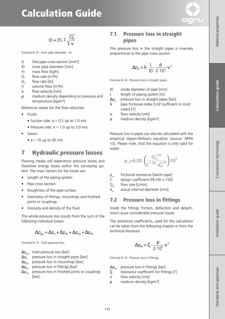
115
Calculation Guide
Mat
eria
l pro
pert
ies
Cal
cula
tio
n g
uid
eC
onne
ctio
n te
chno
logy
Inst
alla
tion
guid
eSt
anda
rds
and
appr
oval
s
⋅ 235.7Q
ID =ν
Formula B.12: Inner pipe diameter - l/s.
A free pipe cross-section [mm²]ID inner pipe diameter [mm]m mass flow [kg/h]Q1 flow rate [m³/h]Q2 flow rate [l/s]V volume flow [m³/h]ν flow velocity [m/s]ρ medium density depending on pressure and
temperature [kg/m³]
Reference values for the flow velocities:
• Fluids:
• Suction side: ν ≈ 0.5 up to 1.0 m/s
• Pressure side: ν ≈ 1.0 up to 3.0 m/s
• Gases:
• ν ≈ 10 up to 30 m/s
7 Hydraulic pressure lossesFlowing media will experience pressure losses and therefore energy losses within the conveying sys-tem. The main factors for the losses are:
• Length of the piping system
• Pipe cross section
• Roughness of the pipe surface
• Geometry of fittings, mountings and finished joints or couplings
• Viscosity and density of the fluid
The whole pressure loss results from the sum of the following individual losses:
RVRARFRges ppppp +++= ΔΔΔΔΔ
Formula B.13: Total pressure loss.
Δpges total pressure loss [bar]ΔpR pressure loss in straight pipes [bar]ΔpRA pressure loss in mountings [bar]ΔpRF pressure loss in fittings [bar]ΔpRV pressure loss in finished joints or couplings
[bar]
7.1 Pressure loss in straight pipes
The pressure loss in the straight pipes is inversely proportional to the pipe cross section.
⋅⋅
⋅⋅ 22102
=IDL
pR νρλΔ
Formula B.14: Pressure loss in straight pipes.
ID inside diameter of pipe [mm]L length of piping system [m]ΔpR pressure loss in straight pipes [bar]λ pipe frictional index 0.02 (sufficient in most
cases) [1]ν flow velocity [m/s]ρ medium density [kg/m³]
Pressure loss in pipes can also be calculated with the empirical Hazen-Williams equation (source: NFPA 13). Please note, that the equation is only valid for water.
pm frictional resistance [bar/m pipe]C design coefficient (PE-HD = 150)Qm flow rate [L/min]dm actual internal diameter [mm]
7.2 Pressure loss in fittingsInside the fittings friction, deflection and detach-ment cause considerable pressure losses
The resistance coefficients, used for the calculation can be taken from the following chapter or from the technical literature.
⋅⋅
⋅ 25102
=RFp νρζΔ
Formula B.15: Pressure loss in fittings.
ΔpRF pressure loss in fittings [bar]ζ resistance coefficient for fittings [1]ν flow velocity [m/s]ρ medium density [kg/m³]

116
Mat
eria
l pro
pert
ies
Cal
cula
tio
n g
uid
eC
onne
ctio
n te
chno
logy
Inst
alla
tion
guid
eSt
anda
rds
and
appr
oval
s
7.2.1 Resistance coefficients for the fittings
Fitting Parameter Resistance coefficient [1] Flow
Bend 90° R ζ1.0 × OD1.5 × OD2.0 × OD4.0 × OD
0.510.410.340.23
α
OD
R
Bend 45° R ζ1.0 × OD1.5 × OD2.0 × OD4.0 × OD
0.340.270.200.15
α
OD
R
Elbow α ζ90°45°30°20°15°10°
~ 1.200.300.140.050.050.04
OD
α
Tee 90° VZ / VS ζZ ζD
(confluence)
0.00.20.40.60.81.0
-1.20-0.400.100.500.700.90
0.060.200.300.400.500.60
VD
VS
VZ
Tee 90° VA / VS ζA ζS
(bifurcation)
0.00.20.40.60.81.0
0.970.900.900.971.101.30
0.10-0.10-0.050.100.200.35
VD
VS
VA
Table B.4: Resistance coefficient for fittings - part 1 (Source: DVS 2210-1).

117
Calculation Guide
Mat
eria
l pro
pert
ies
Cal
cula
tio
n g
uid
eC
onne
ctio
n te
chno
logy
Inst
alla
tion
guid
eSt
anda
rds
and
appr
oval
s
Fitting Parameter Resistance coefficient [1] Flow
Reduction OD2 / OD1 4° > α < 8° α < 16° α < 24°
(pipe extension)
1.21.41.61.82.0
0.100.200.501.201.90
0.150.300.801.803.10
0.200.501.503.005.30 α
/2
OD1
OD2
Reduction OD2 / OD1 α < 4° α < 8° α < 20°
(pipe throat)
1.21.41.61.82.0
0.0460.0670.0760.0310.034
0.0230.0330.0380.0410.042
0.0100.0130.0150.0160.017
OD1
OD2
α/2
Table B.5: Resistance coefficient for fittings - part 2 (Source: DVS 2210-1).
Positive ζ-values represent a pressure drop, whereas negative ζ-values represent a pressure increase.
VA outgoing volume flowVD continuous volume flowVS total volume flowVZ additional volume flow
7.3 Pressure loss in mountingsThe resistance coefficients, used for the calculation can be taken from the following chapter or from the technical literature.
⋅⋅
⋅ 25102
=RAp νρζΔ
Formula B.16: Pressure loss in mountings.
ΔpRA pressure loss in mountings [bar]ζ resistance coefficient for mountings [1]ν flow velocity [m/s]ρ density of medium [kg/m³]
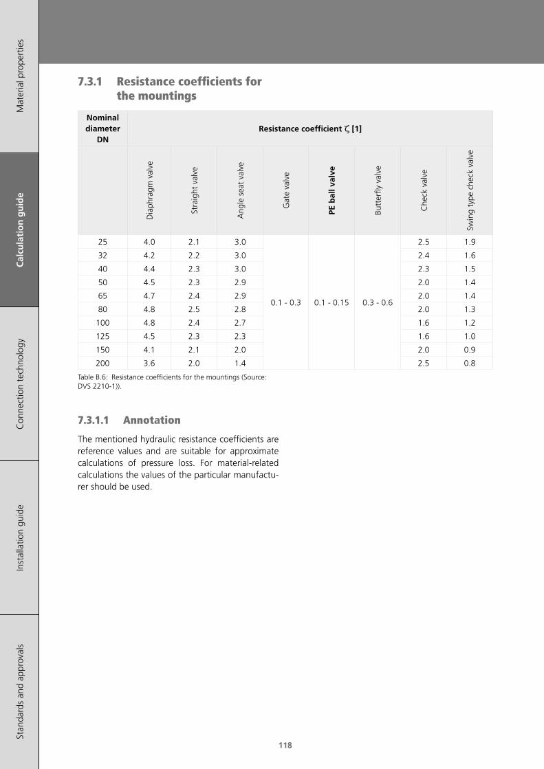
118
Mat
eria
l pro
pert
ies
Cal
cula
tio
n g
uid
eC
onne
ctio
n te
chno
logy
Inst
alla
tion
guid
eSt
anda
rds
and
appr
oval
s
7.3.1 Resistance coefficients for the mountings
Nominal diameter
DNResistance coefficient ζ [1]
Dia
phra
gm v
alve
Stra
ight
val
ve
Ang
le s
eat
valv
e
Gat
e va
lve
PE b
all v
alve
Butt
erfly
val
ve
Che
ck v
alve
Swin
g ty
pe c
heck
val
ve
25 4.0 2.1 3.0
0.1 - 0.3 0.1 - 0.15 0.3 - 0.6
2.5 1.9
32 4.2 2.2 3.0 2.4 1.6
40 4.4 2.3 3.0 2.3 1.5
50 4.5 2.3 2.9 2.0 1.4
65 4.7 2.4 2.9 2.0 1.4
80 4.8 2.5 2.8 2.0 1.3
100 4.8 2.4 2.7 1.6 1.2
125 4.5 2.3 2.3 1.6 1.0
150 4.1 2.1 2.0 2.0 0.9
200 3.6 2.0 1.4 2.5 0.8
Table B.6: Resistance coefficients for the mountings (Source: DVS 2210-1)).
7.3.1.1 Annotation
The mentioned hydraulic resistance coefficients are reference values and are suitable for approximate calculations of pressure loss. For material-related calculations the values of the particular manufactu-rer should be used.

119
Calculation Guide
Mat
eria
l pro
pert
ies
Cal
cula
tio
n g
uid
eC
onne
ctio
n te
chno
logy
Inst
alla
tion
guid
eSt
anda
rds
and
appr
oval
s
7.3.2 Selection criteria for the mountings
Selection criteria
AssessmentD
iaph
ragm
val
ve,
stra
ight
val
ve, a
ngle
se
at v
alve
Gat
e va
lve
PE b
all v
alve
acc
. to
EN
122
01 /
EN
155
5
Butt
erfly
val
ve
Che
ck v
alve
Swin
g ty
pe c
heck
va
lve
Flowresistance
big low low moderate big moderate
Aperture and closing time
medium medium short short short short
Operation moment
low lowmoderate (without gear)
low (with gear)moderate - -
Wear moderate low low moderate moderate moderate
Flowregulation
suitable less suitable less suitableless suita-
ble- -
Face‑to‑face length acc. to
F‑rowmedium big
welded directly into the pipeline
big medium big
Face‑to‑face length acc. to
K‑row- - low - low
Table B.7: Selection criteria for the mountings (Source: DVS 2210-1).
F-row Flange design (DIN 3202-1)K-row Inter-flange design (DIN 3202-3)

120
Mat
eria
l pro
pert
ies
Cal
cula
tio
n g
uid
eC
onne
ctio
n te
chno
logy
Inst
alla
tion
guid
eSt
anda
rds
and
appr
oval
s
7.4 Pressure loss in finished joints or couplings
An exact calculation of the pressure loss is not possi-ble, because the types and the qualities of the joints (welding joints, unions and flange joints) may vary.
It is recommended to use a resistance coefficient of ζRV = 0.1 for the consideration of the joints (butt and socket welding) and flanges in the pressure loss calculation.
⋅⋅
⋅ 25102νpRV =
ρζΔ
Formula B.17: Pressure loss in finished joints or couplings.
ζ resistance coefficient for the mountings [1]ν flow velocity [m/s]ρ density of the medium [kg/m³]
8 ElongationElongations of plastic piping systems are caused by the changes in the operating or test process. Fol-lowing influence factors are possible:
• Elongation due to temperature change
• Elongation due to internal pressure
• Elongation due to chemical influence
8.1 Elongation caused by temperature change
If the piping system is exposed to different tempera-tures (operating or ambient temperatures) its posi-tion changes depending on the moving possibilities of each pipeline. A pipeline is assumed as the dis-tance between two restraints.
The elongation is calculated as follows:
⋅⋅ TLLT = ΔΔ α
Formula B.18: Elongation due to temperature change.
L pipe length [m]α coefficient of linear expansion [mm/(m×K)]ΔLT elongation due to temperature change [mm]ΔT temperature difference [K]
For the determination of ΔT the lowest and the highest possible pipe wall temperature TR during the installation, operation or standstill has to be considered.
Linear expansion coef-ficient α
PE 100 & PE 100‑RC 0.18
PE‑Xa 0.14
Table B.8: Linear expansion coefficient.
8.2 Elongation caused by internal pressure
The elongation due to internal pressure of a closed and friction-free installed piping system is:
⋅
⋅⋅⋅⋅
( )L
IDOD
E
pL
C
P
−
−=
1
210.1
2
2Δ μ
Formula B.19: Elongation due to internal pressure.
EC_100 mincreep modulus [N/mm²]ID pipe inside diameter [mm]L length of piping system [mm]OD pipe outside diameter [mm]p operating pressure [bar]ΔLP elongation by internal pressure [mm]μ Poisson ratio 0.38 [1]
9 Restraint loadRestraints (fixed points) should prevent a sliding or moving of the piping system in every direction. Fur-thermore restraint serve as compensations for the reaction forces when using compensators (sliding sockets and push-fit fittings). A restraint has to be dimensioned for all possible forces:
• Stress through restrained thermal expansion
• Weight of the vertical piping systems
• Specific weight of the fluid
• Operating pressure
• Inherent resistance of the compensators

121
Calculation Guide
Mat
eria
l pro
pert
ies
Cal
cula
tio
n g
uid
eC
onne
ctio
n te
chno
logy
Inst
alla
tion
guid
eSt
anda
rds
and
appr
oval
s
Restraints which haven‘t been determined should be placed in a way that the direction changes in the pipeline are used for the absorption of the elonga-tions.
Possible restraints are the edges of the fitting so-ckets or special restraint fittings.
Figure B.2: Restraint fitting.
Swinging clips or the clamping of the pipes are not suitable as restraints.
9.1 Rigid systemRestraining the elongation of a piping system leads to a fixed system.
Rigid or fixed piping length has no compensation elements. and has to be treated as a special case during the dimensioning.
Following parameters have to be calculated:
• Restraint load
• Permissible guiding element distance in consi-deration of the critical buckling length
• Occuring tensile and compressive stresses
The highest restraint loads occur on the straight, axially fixed pipe sections. In general it is calculated using the following formula.
⋅⋅= CRFP EAF ε
Formula B.20: Dog bone load.
AR annular surface of the pipe wall [mm²]EC creep modulus for t = 100 min [N/mm²]FFP restraint loads in the fixed pipe section [N]ε prevented longitudinal expansion (by heat
expansion, internal pressure) [1]
Mean temperature Tm [°C]
Creep modulus EC for 100 min [N/mm²]
≤10 833
20 634
30 468
40 362
50 283
60 230
Table B.9: Creep moduli for 100 minutes (Source: DVS 2210-1 suppl. 1).
9.1.1 Load by thermal expansion
Formula B.21: Thermal expansion.
α coefficient of linear expansion [1/K]ΔT max. temperature difference [K]ε prevented longitudinal extension [1]
9.1.2 Load by internal pressure
Formula B.22: Extension due to the internal pressure.
p operating pressure [bar]μ Poisson‘s ratio 0.38 [1]EC creep modulus for t = 100 min [N/mm²]OD pipe outside diameter [mm]ID pipe inside diameter [mm]ε prevented longitudinal extension by internal
pressure [1]
9.1.3 Load by swelling
Caution: a fixed system where a material swelling is possible, should be generally avoided. Reason: the swelling causes a material weakening.

122
Mat
eria
l pro
pert
ies
Cal
cula
tio
n g
uid
eC
onne
ctio
n te
chno
logy
Inst
alla
tion
guid
eSt
anda
rds
and
appr
oval
s
10 Expansion bendsChanges in length are caused by changes in opera-ting or ambient temperature. If the piping systems are installed above ground, the axial movements have to be compensated sufficiently.
In most cases, changes of direction of the pipe sec-tions can be used for the absorption of the elon-gations. Otherwise, expansion bends have to be installed.
The minimum length of the expansion bend is cal-culated as follows:
Formula B.23: Minimum length of expansion bends.
LS min. length of the expansion bend [mm]k material specific proportionality factor [1]ΔL system length of the expansion bend [mm]OD pipe outside diameter [mm]
If the result cannot be realised, compensators with minimal friction coefficient have to be used. Depen-ding on the construction, they may be applied as axial, lateral or angular compensators.
PE
k-value
0 °C 10 °C 30 °C 40 °C 60°C
multiple temperature changes
16 17 23 28 -
single temperature change
12 12 16 17 -
Note: for the calculation of the k-values an installa-tion temperature of 20 °C was taken into account. At lower temperatures the impact strength of the material has to be considered.
The k-values can be reduced by 30% for pressurels pipes (e.g. ventilation).
Between two restraints, a compensator has to be installed. An appropriate guiding of the piping at the loose points has to be ensured. For that matter the resulting reaction forces have to be taken into account.
A
A
L
Δ L Δ L
L S
Figure B.3: L-compensation.
A
SB
A
L
ΔL ΔL
L S
Figure B.4: Z-compensation.
A
SB
A
L L
ΔL ΔL
L S
Figure B.5: U-compensation.
A restraintsSB slide bearing

123
Calculation Guide
Mat
eria
l pro
pert
ies
Cal
cula
tio
n g
uid
eC
onne
ctio
n te
chno
logy
Inst
alla
tion
guid
eSt
anda
rds
and
appr
oval
s
10.1 Calculation of straight lengths
OD change in length ∆L [mm]
[mm] 50 100 150 200 250 300 350 400 500
16 750 1050 1300 1500 1650 1850 1950 2100 2350
20 850 1200 1450 1650 1850 2050 2200 2350 2600
25 950 1300 1600 1850 2100 2300 2450 2600 2950
32 1050 1500 1850 2100 2350 2550 2800 2950 3300
40 1200 1650 2050 2350 2600 2850 3100 3300 3700
50 1300 1850 2300 2600 2950 3200 3450 3700 4150
63 1500 2100 2550 2950 3300 3600 3900 4150 4650
75 1600 2300 2800 3200 3600 3900 4250 4550 5050
90 1750 2500 3050 3500 3900 4300 4650 4950 5550
110 1950 2750 3350 3900 4350 4750 5150 5500 6100
125 2100 2950 3600 4150 4600 5050 5450 5850 6500
140 2200 3100 3800 4400 4900 5350 5800 6200 6900
160 2350 3300 4050 4700 5200 5700 6200 6600 7400
180 2500 3500 4300 4950 5550 6050 6550 7000 7800
200 2600 3700 4550 5200 5850 6400 6900 7400 8250
225 2800 3900 4800 5550 6200 6800 7300 7800 8750
250 2950 4150 5050 5850 6500 7150 7700 8250 9200
280 3100 4400 5350 6200 6900 7550 8150 8750 9750
315 3300 4650 5700 6550 7300 8000 8650 9250 10350
355 3500 4900 6000 6950 7750 8500 9200 9800 11000
400 3700 5200 6400 7400 8250 9050 9750 10400 11650
450 3900 5550 6800 7800 8750 9600 10350 11050 12350
500 4150 5850 7150 8250 9200 10100 10900 11650 13000
560 4400 6200 7550 8750 9750 10700 11550 12350 13800
630 4650 6550 8000 9250 10350 11350 12250 13100 14600
Table B.10: Straight lenghts in mm for PE pipes calculated acc. to formula A.23 with k-value=26 (rounded up in 50 mm steps).
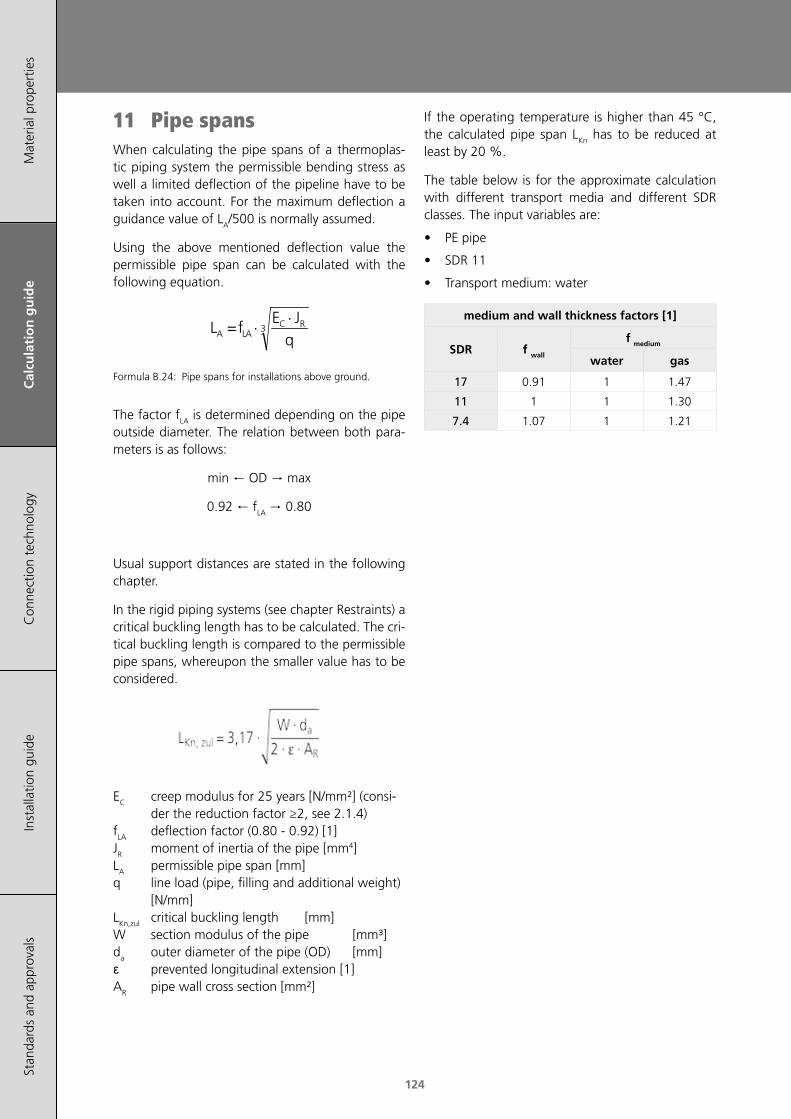
124
Mat
eria
l pro
pert
ies
Cal
cula
tio
n g
uid
eC
onne
ctio
n te
chno
logy
Inst
alla
tion
guid
eSt
anda
rds
and
appr
oval
s
11 Pipe spansWhen calculating the pipe spans of a thermoplas-tic piping system the permissible bending stress as well a limited deflection of the pipeline have to be taken into account. For the maximum deflection a guidance value of LA/500 is normally assumed.
Using the above mentioned deflection value the permissible pipe span can be calculated with the following equation.
⋅⋅ 3
qJE
fL RCLAA =
Formula B.24: Pipe spans for installations above ground.
The factor fLA is determined depending on the pipe outside diameter. The relation between both para-meters is as follows:
min ← OD → max
0.92 ← fLA → 0.80
Usual support distances are stated in the following chapter.
In the rigid piping systems (see chapter Restraints) a critical buckling length has to be calculated. The cri-tical buckling length is compared to the permissible pipe spans, whereupon the smaller value has to be considered.
EC creep modulus for 25 years [N/mm²] (consi-der the reduction factor ≥2, see 2.1.4)
fLA deflection factor (0.80 - 0.92) [1]JR moment of inertia of the pipe [mm4]LA permissible pipe span [mm]q line load (pipe, filling and additional weight)
[N/mm]LKn,zul critical buckling length [mm]W section modulus of the pipe [mm³]da outer diameter of the pipe (OD) [mm]ε prevented longitudinal extension [1]AR pipe wall cross section [mm²]
If the operating temperature is higher than 45 °C, the calculated pipe span LKn has to be reduced at least by 20 %.
The table below is for the approximate calculation with different transport media and different SDR classes. The input variables are:
• PE pipe
• SDR 11
• Transport medium: water
medium and wall thickness factors [1]
SDR f wall
f medium
water gas
17 0.91 1 1.47
11 1 1 1.30
7.4 1.07 1 1.21
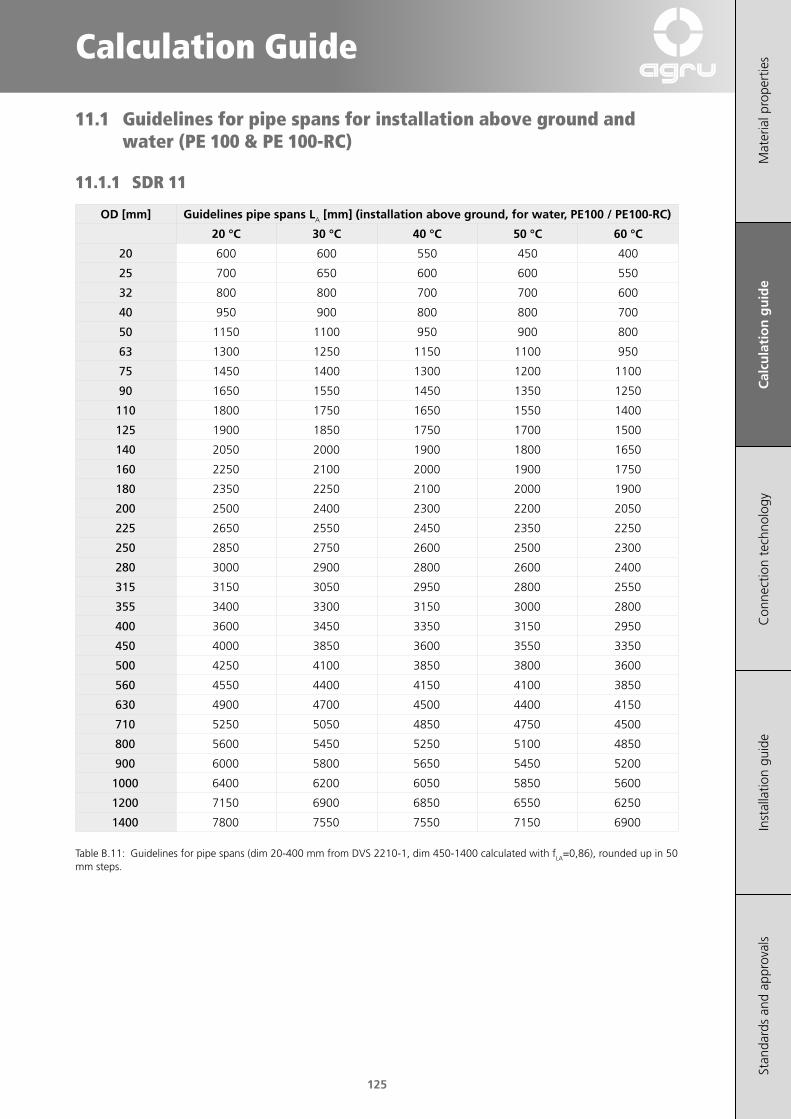
125
Calculation Guide
Mat
eria
l pro
pert
ies
Cal
cula
tio
n g
uid
eC
onne
ctio
n te
chno
logy
Inst
alla
tion
guid
eSt
anda
rds
and
appr
oval
s
11.1 Guidelines for pipe spans for installation above ground and water (PE 100 & PE 100-RC)
11.1.1 SDR 11
OD [mm] Guidelines pipe spans LA [mm] (installation above ground, for water, PE100 / PE100-RC)
20 °C 30 °C 40 °C 50 °C 60 °C
20 600 600 550 450 400
25 700 650 600 600 550
32 800 800 700 700 600
40 950 900 800 800 700
50 1150 1100 950 900 800
63 1300 1250 1150 1100 950
75 1450 1400 1300 1200 1100
90 1650 1550 1450 1350 1250
110 1800 1750 1650 1550 1400
125 1900 1850 1750 1700 1500
140 2050 2000 1900 1800 1650
160 2250 2100 2000 1900 1750
180 2350 2250 2100 2000 1900
200 2500 2400 2300 2200 2050
225 2650 2550 2450 2350 2250
250 2850 2750 2600 2500 2300
280 3000 2900 2800 2600 2400
315 3150 3050 2950 2800 2550
355 3400 3300 3150 3000 2800
400 3600 3450 3350 3150 2950
450 4000 3850 3600 3550 3350
500 4250 4100 3850 3800 3600
560 4550 4400 4150 4100 3850
630 4900 4700 4500 4400 4150
710 5250 5050 4850 4750 4500
800 5600 5450 5250 5100 4850
900 6000 5800 5650 5450 5200
1000 6400 6200 6050 5850 5600
1200 7150 6900 6850 6550 6250
1400 7800 7550 7550 7150 6900
Table B.11: Guidelines for pipe spans (dim 20-400 mm from DVS 2210-1, dim 450-1400 calculated with fLA=0,86), rounded up in 50 mm steps.

126
Mat
eria
l pro
pert
ies
Cal
cula
tio
n g
uid
eC
onne
ctio
n te
chno
logy
Inst
alla
tion
guid
eSt
anda
rds
and
appr
oval
s
13 Flow characteristics (Nomogram)
The following flow characteristics nomogram is used for the rough estimate of the flow velocity, pressure loss and flow rate.
When fittings are used in the pipeline, then up to 20 m of pipe length are added for each tee, reducer and 90° elbow, about 10 m of pipe for each bend (r = d) and about 5 m of pipe length for each bend (r = 1.5 × d). That estimation applies to an average flow velocity
12 Nominal stiffnessThe ring stiffness SN describes the carrying capaci-ty of the pipe crown. SN (unit: kN/m2) means stiff-ness number and is divided into classes, which are determined experimentally. 21 days after the pipe production, the pipe is deformed to ca. 3% and the surface load, needed for the deformation is measu-red. A pipe with a nominal stiffness SN 2 can with-stand a surface load of 2 kN/m2 at a deformation of < 3%.
The influence of the stiffness on flexible plastic pi-ping systems is overestimated. The pipe must offer a sufficient stiffness during the installation to bear the loads resulting from the compaction. With a good compaction work within the embedment the soil carries the occuring loads. Due to the deformation of the pipe (usually 2 - 3 %) the load isn‘t trans-ferred to the pipe. After a period of approximately 2 years (relaxation) the pipe lies load-free in the soil. A nominal stiffness of 8 kN/m² is regarded as opti-mal and sufficient.
The ring stiffness is classified into the following gra-des after EN 12201-2:
SDR ISO S SN [kN/m2]
41 20 1,3
33 16 2,5
26 12,5 5,3
21 10 10,4
17 8 20,3
13,6 6,3 41,7
11 5 83,3
9 4 162,8
7,4 3,2 317,9
6 2,5 668,7
Table B.12: Initial stiffness of pipes (caclulated with Young’s Modulus E = 1000 MPa)

127
Calculation Guide
Mat
eria
l pro
pert
ies
Cal
cula
tio
n g
uid
eC
onne
ctio
n te
chno
logy
Inst
alla
tion
guid
eSt
anda
rds
and
appr
oval
s
40
50
60
70
80
90
100
200
300
400
500
600
0.10
0.15
0.2
0.30.40.5
1.0
1.5
2
345
10
15
20
30
4050
100
150
200
300
400500
1000
2000
300040005000
0.10
0.15
0.2
0.3
0.4
0.5
1.0
1.5
2
3
4
5
10
20
0.02
0.03
0.04
0.05
0.1
0.2
0.3
0.4
0.5
1
2
3
4
5
10
20
30
40
50
100
Q [l/s] Δp/L [mbar/m]ν [m/s]ID [mm]
Figure B.6: Flow characteristics nomogram. ID inside diameter of the pipe [mm]Q2 flow rate [l/s]ν flow velocity [m/s]Δp/L pressure loss per meter pipe length [mbar/m]
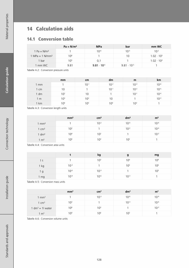
128
Mat
eria
l pro
pert
ies
Cal
cula
tio
n g
uid
eC
onne
ctio
n te
chno
logy
Inst
alla
tion
guid
eSt
anda
rds
and
appr
oval
s
14 Calculation aids
14.1 Conversion table
Pa = N/m² MPa bar mm WC
1 Pa = N/m² 1 10-6 10-5 10-2
1 MPa = 1 N/mm² 106 1 10 1.02 · 105
1 bar 105 0,1 1 1.02 · 104
1 mm WC 9.81 9.81 · 10-6 9.81 · 10-5 1
Tabelle A.2: Conversion pressure units
mm cm dm m km
1 mm 1 10-1 10-2 10-3 10-6
1 cm 10 1 10-1 10-2 10-5
1 dm 102 10 1 10-1 10-4
1 m 103 102 10 1 10-3
1 km 106 105 104 103 1
Tabelle A.3: Conversion length units
mm² cm² dm² m²
1 mm² 1 10-2 10-4 10-6
1 cm² 102 1 10-2 10-4
1 dm² 104 102 1 10-2
1 m² 106 104 102 1
Tabelle A.4: Conversion area units
t kg g mg
1 t 1 103 106 109
1 kg 10-3 1 103 106
1 g 10-6 10-3 1 103
1 mg 10-9 10-6 10-3 1
Tabelle A.5: Conversion mass units
mm3 cm3 dm3 m3
1 mm3 1 10-3 10-6 10-9
1 cm3 103 1 10-3 10-6
1 dm3 = 1l water 106 103 1 10-3
1 m3 109 106 103 1
Tabelle A.6: Conversion volume units

129
Calculation Guide
Mat
eria
l pro
pert
ies
Cal
cula
tio
n g
uid
eC
onne
ctio
n te
chno
logy
Inst
alla
tion
guid
eSt
anda
rds
and
appr
oval
s
OD [mm] DN inch
10 6 -
12 8 -
16 10 -
20 15 1/2
25 20 3/4
32 25 1
40 32 11/4
50 40 11/2
63 50 2
75 65 21/2
90 80 3
110 100 4
125 100 41/2
140 125 5
160 150 6
180 150 7
200 200 8
225 200 9
250 250 10
280 250 11
315 300 12
355 350 14
400 400 16
450 500 18
500 500 20
560 600 22
630 600 25
710 700 28
800 800 32
900 900 36
1000 1000 40
1200 1200 48
Relation between the outer diameter (OD), the no-minal diameter, and the inch dimensions.
1
metre
[m]
3.28
feet
[ft]
39.37
inch
[in]
1
litre
[l]
0.264
gallons
[Ga]
0.035
cubic feet
[ft3]
1
kilogram
[kg]
2.204
pounds
[lbs]
9.81
Newton
[N]
1
bar
[bar]
14.505
pound/sq. inch
[psi]
100
kilopascal
[kPa]
Tabelle A.7: Conversion SI-units
14.2 Formula
14.2.1 Circle
Area
Circumference

130
Mat
eria
l pro
pert
ies
Cal
cula
tio
n g
uid
eC
onne
ctio
n te
chno
logy
Inst
alla
tion
guid
eSt
anda
rds
and
appr
oval
s
14.2.2 Cylinder
Lateral area
Surface
Volume
14.2.3 Circular ring
Area
14.2.4 Hollow cylinder (pipe)
Volume
A area [mm2]
Am lateral area [mm2]
AO surface [mm2]
V volume [mm3]
U circumference [mm]
r radius [mm]
D diameter (outside) [mm]
d diameter (inside) [mm]
h height [mm]
b wall thickness [mm]

131
Mat
eria
l pro
pert
ies
Cal
cula
tion
guid
eC
on
nec
tio
n t
ech
no
log
yIn
stal
latio
n gu
ide
Stan
dard
s an
d ap
prov
als
Connection technology
131
Cal
cula
tio
n g
uid
e
1 General requirements 133
2 Heated tool butt welding (HS) 135
3 Heated tool socket welding 138
4 Electro-fusion welding DIM 20-500mm monofilar 140
5 Electro-fusion welding DIM 560-1400mm bifilar 144
6 Saddles 148
7 Pressure test 153

132
Mat
eria
l pro
pert
ies
Cal
cula
tion
guid
eC
on
nec
tio
n t
ech
no
log
yIn
stal
latio
n gu
ide
Stan
dard
s an
d ap
prov
als

133
Mat
eria
l pro
pert
ies
Cal
cula
tion
guid
eC
on
nec
tio
n t
ech
no
log
yIn
stal
latio
n gu
ide
Stan
dard
s an
d ap
prov
als
Connection technology
1 General requirements(applies to all welding processes)
The quality of welded joints depends on the quali-fication of the welder, the suitability of the utilized equipment and devices as well as on compliance with the welding standards. The welded joint can be tested by means of non-destructive and/or de-structive methods.
The welding work must be monitored. Type and range of supervision has to be agreed between the contract partners. It is recommended to record the welding data in welding protocols or on data carri-ers.
Every welder has to be trained and has to be in possession of a valid qualification certificate. The intended application range may be decisive for the kind of qualification. For the industrial piping sys-tem construction, the technical code DVS 2212-1 is valid.
The equipment and devices which are used for wel-ding must comply with the requirements in DVS 2208-1. The welding of plastics for indoor applica-tions is described in the technical codes DVS 1905-1 and -2.
1.1 Requirements for weldingThe welding zone must be protected against bad weather influences (e.g. wind, moisture).
Figure C.1: Preparation of the welding zone acc. to DVS
lf it is ensured by suitable measures (e.g. prehea-ting, tent, heating) that the conditions are suitable for welding, work may be carried out at any outside temperature insofar as the welder is not hindered in his handling. (fig. D.1)
An additional proof must be provided by car-rying out sample welds under the mentioned conditions
lf the semi-finished product (pipe or fitting) is hea-ted up unevenly under influence of sunshine, a tem-perature compensation in the area of the welding joint can be reached by covering. A cooling down during the welding process by ventilation has to be avoided. During welding the pipe ends have to be closed additionally to avoid stack effect.
PE-HD-pipes from coils are oval and bent immedia-tely after uncoiling. The pipe end must be prepared before welding, e.g. by careful heating up with a hot-air equipment and/or use of a suitable clamping res. re-rounding device.
The joining zones of the components to be welded must be undamaged and have to be free of conta-minations (e.g. dirt, grease, shavings).
Before welding the joining areas have to be clea-ned with a special cleaning agent (PE cleaning agent consisting of isopropanol, acetone or ethanol acc. to DVGW VP 603)
Caution: Pipes and fittings contaminated with si-licone grease cannot be cleaned with most of the cleaning agents. In that case brake cleaner fluid can be used. However the suitability has to be checked with the manufacturer and additional welds have to be carried out.
During all welding procedures the welding area has to be free of flextural stresses (e.g. by careful sto-rage, roller blocks). Also a correct axial alingment has to be ensured.
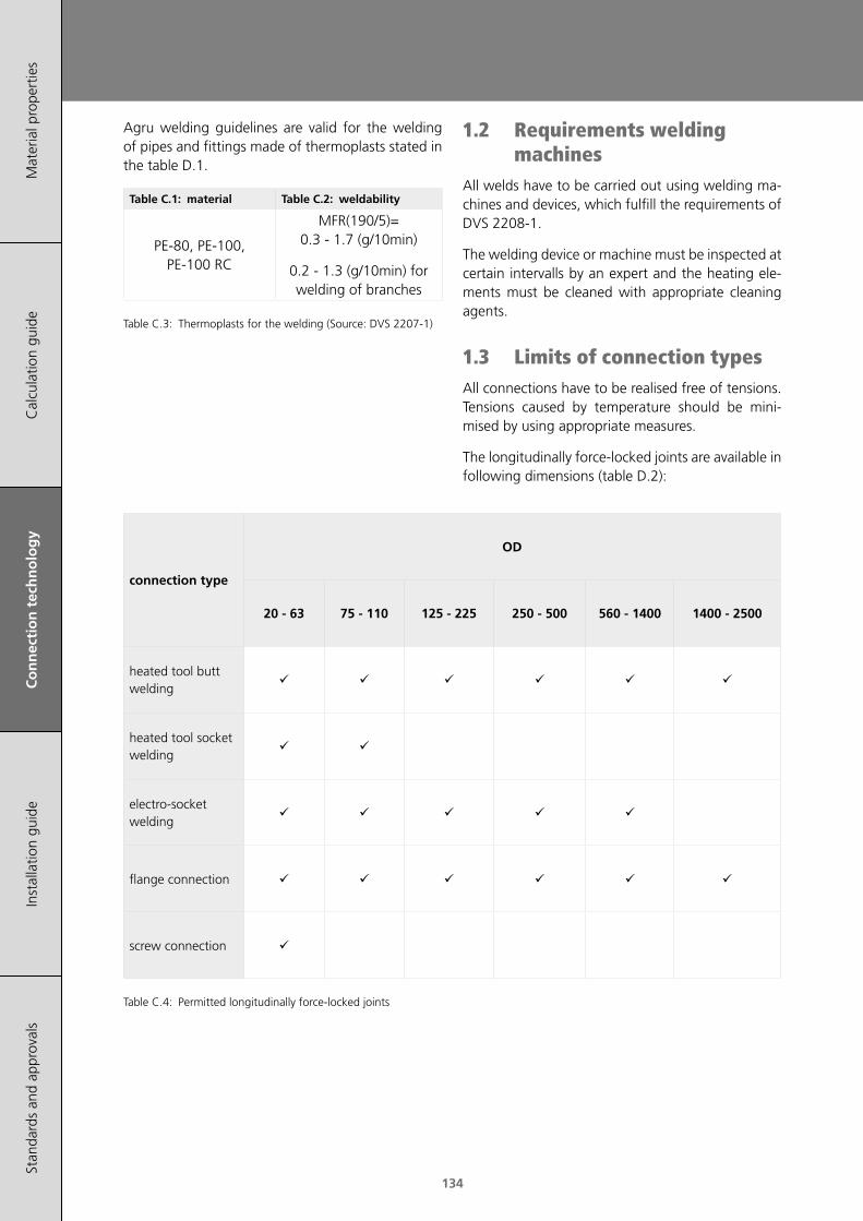
134
Mat
eria
l pro
pert
ies
Cal
cula
tion
guid
eC
on
nec
tio
n t
ech
no
log
yIn
stal
latio
n gu
ide
Stan
dard
s an
d ap
prov
als
Agru welding guidelines are valid for the welding of pipes and fittings made of thermoplasts stated in the table D.1.
Table C.1: material Table C.2: weldability
PE-80, PE-100, PE-100 RC
MFR(190/5)= 0.3 - 1.7 (g/10min)
0.2 - 1.3 (g/10min) for welding of branches
Table C.3: Thermoplasts for the welding (Source: DVS 2207-1)
connection type
OD
20 - 63 75 - 110 125 - 225 250 - 500 560 - 1400 1400 - 2500
heated tool butt welding
heated tool socket welding
electro-socket welding
flange connection
screw connection
Table C.4: Permitted longitudinally force-locked joints
1.2 Requirements welding machines
All welds have to be carried out using welding ma-chines and devices, which fulfill the requirements of DVS 2208-1.
The welding device or machine must be inspected at certain intervalls by an expert and the heating ele-ments must be cleaned with appropriate cleaning agents.
1.3 Limits of connection typesAll connections have to be realised free of tensions. Tensions caused by temperature should be mini-mised by using appropriate measures.
The longitudinally force-locked joints are available in following dimensions (table D.2):

135
Mat
eria
l pro
pert
ies
Cal
cula
tion
guid
eC
on
nec
tio
n t
ech
no
log
yIn
stal
latio
n gu
ide
Stan
dard
s an
d ap
prov
als
Connection technology
2 Heated tool butt welding (HS)
(acc. to DVS2207-1)
With the heated tool butt welding process, the joi-ning zones of the components to be welded are ali-gned under pressure on the heated tool (alignment), heated up to the welding temperature with reduced pressure (heating up) and joined under pressure (joi-ning) after removal of the heated tool (changeover).
200
205
210
215
220
0 10 20 30 40 50
wallthickness, s [mm]
heat
er p
late
tem
pera
tur
°C
lower limit
upper limit
Figure C.2: Heated tool temperature as a function of the wall thickness
Heated tool butt welding is usually conducted at temperatures between 200 and 220°C.
ln principle the upper temperature limit is to be uti-lised for smaller wall thickness, the lower tempera-ture limit for bigger wall thicknesses (see fig. D.2). The upper temperature has to be chosen for PE 100 as well.
Nominal wall thickness s
[mm]
Bead height [mm] pressure= 0.15 N/mm2
Heating-up time tAW [s] pressure≤ 0.01 N/mm2
Max.changeover time tU [s]
Max. joining pressure build-.
up time tF [s]
Cooling time tAK [min.] pressure
= 0.1 N/mm2
up to 4,5 0.5 up to 45 5 5 see table 4
4,5 – 7 1.0 45 – 70 5 – 6 5 – 6 see table 4
7 – 12 1.5 70 – 120 6 – 8 6 – 8 see table 4
12 – 19 2.0 120 – 190 8 – 10 8 – 11 see table 4
19 – 26 2.5 190 – 260 10 – 12 11 – 14 see table 4
26 – 37 3.0 260 – 370 12 – 16 14 – 19 see table 4
37 – 50 3.5 370 – 500 16 – 20 19 – 25 see table 4
50 – 70 4.0 500 – 700 20 – 25 25 – 35 see table 4
Table C.5: Heated tool butt welding parameters (Source: DVS 2207-1)
Nominal wall thickness s [mm]
Cooling time tAK (min. values) under joining pressure p = 0.15 ±0,01 N/mm2
depending on the ambient temperature
up to 4,5 up to 15 °C [min] 15 °C – 25 °C [min] 25 °C – 40 °C [min]
4,5 – 7 4.0 5.0 6.5
7 – 12 4.0 – 6.0 5.0 – 7.5 6.5 – 9.5
12 – 19 6.0 – 9.5 7.5 – 12 9.5 – 15.5
19 – 26 9.5 – 14 12 – 18 15.5 – 24
26 – 37 14 – 19 18 – 24 24 – 32
37 – 50 19 – 27 24 – 34 32 – 45
50 – 70 27 – 36 34 – 46 45 – 61
Table C.6: Cooling times for pipes and fittings made of PE depending on the ambient temperature (Source: DVS 2207-1)
tAg tAw tU tF tAk
Total welding time
Total joining time
Heating-uppressure
Alignementpressure
Figure C.3: Process steps of heated tool butt welding
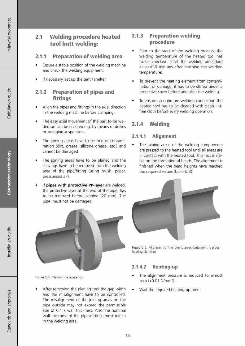
136
Mat
eria
l pro
pert
ies
Cal
cula
tion
guid
eC
on
nec
tio
n t
ech
no
log
yIn
stal
latio
n gu
ide
Stan
dard
s an
d ap
prov
als
2.1 Welding procedure heated tool butt welding:
2.1.1 Preparation of welding area
• Ensure a stable position of the welding machine and check the welding equipment.
• If necessary, set up the tent / shelter.
2.1.2 Preparation of pipes and fittings
• Align the pipes and fittings in the axial direction in the welding machine before clamping.
• The easy axial movement of the part to be wel-ded-on can be ensured e.g. by means of dollies or swinging suspension.
• The joining areas have to be free of contami-nation (dirt, grease, silicone grease, etc.) and cannot be damaged
• The joining areas have to be planed and the shavings have to be removed from the welding area of the pipe/fitting (using brush, paper, pressurised air).
• If pipes with protective PP-layer are welded, the protective layer at the end of the pipe has to be removed before planing (20 mm). The pipe must not be damaged.
Figure C.4: Planing the pipe ends
• After removing the planing tool the gap width and the misalignment have to be controlled. The misalignment of the joining areas on the pipe outside may not exceed the permissible size of 0,1 x wall thickness. Also the nominal wall thickness of the pipes/fittings must match in the welding area.
2.1.3 Preparation welding procedure
• Prior to the start of the welding process, the welding temperature of the heated tool has to be checked. (start the welding procedure at least10 minutes after reaching the welding temperature).
• To prevent the heating element from contami-nation or damage, it has to be stored under a protective cover before and after the welding.
• To ensure an optimum welding connection the heated tool has to be cleaned with clean lint-free cloth before every welding operation.
2.1.4 Welding
2.1.4.1 Alignment
• The joining areas of the welding components are pressed to the heated tool until all areas are in contact with the heated tool. This fact is visi-ble on the formation of beads. The alignment is finished when the bead heights have reached the required values (table D.3).
Figure C.5: Alignment of the joining areas (between the pipes: heating element)
2.1.4.2 Heating-up
• The alignment pressure is reduced to almost zero (<0.01 N/mm²) .
• Wait the required heating-up time.
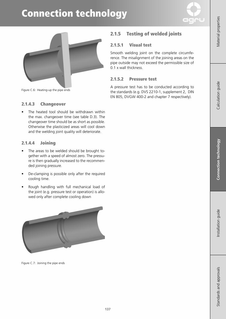
137
Mat
eria
l pro
pert
ies
Cal
cula
tion
guid
eC
on
nec
tio
n t
ech
no
log
yIn
stal
latio
n gu
ide
Stan
dard
s an
d ap
prov
als
Connection technology
Figure C.6: Heating-up the pipe ends
2.1.4.3 Changeover
• The heated tool should be withdrawn within the max. changeover time (see table D.3). The changeover time should be as short as possible. Otherwise the plasticized areas will cool down and the welding joint quality will deteriorate.
2.1.4.4 Joining
• The areas to be welded should be brought to-gether with a speed of almost zero. The pressu-re is then gradually increased to the recommen-ded joining pressure.
• De-clamping is possible only after the required cooling time.
• Rough handling with full mechanical load of the joint (e.g. pressure test or operation) is allo-wed only after complete cooling down
Figure C.7: Joining the pipe ends
2.1.5 Testing of welded joints
2.1.5.1 Visual test
Smooth welding joint on the complete circumfe-rence. The misalignment of the joining areas on the pipe outside may not exceed the permissible size of 0.1 x wall thickness.
2.1.5.2 Pressure test
A pressure test has to be conducted according to the standards (e.g. DVS 2210-1, supplement 2, DIN EN 805, DVGW 400-2 and chapter 7 respectively).
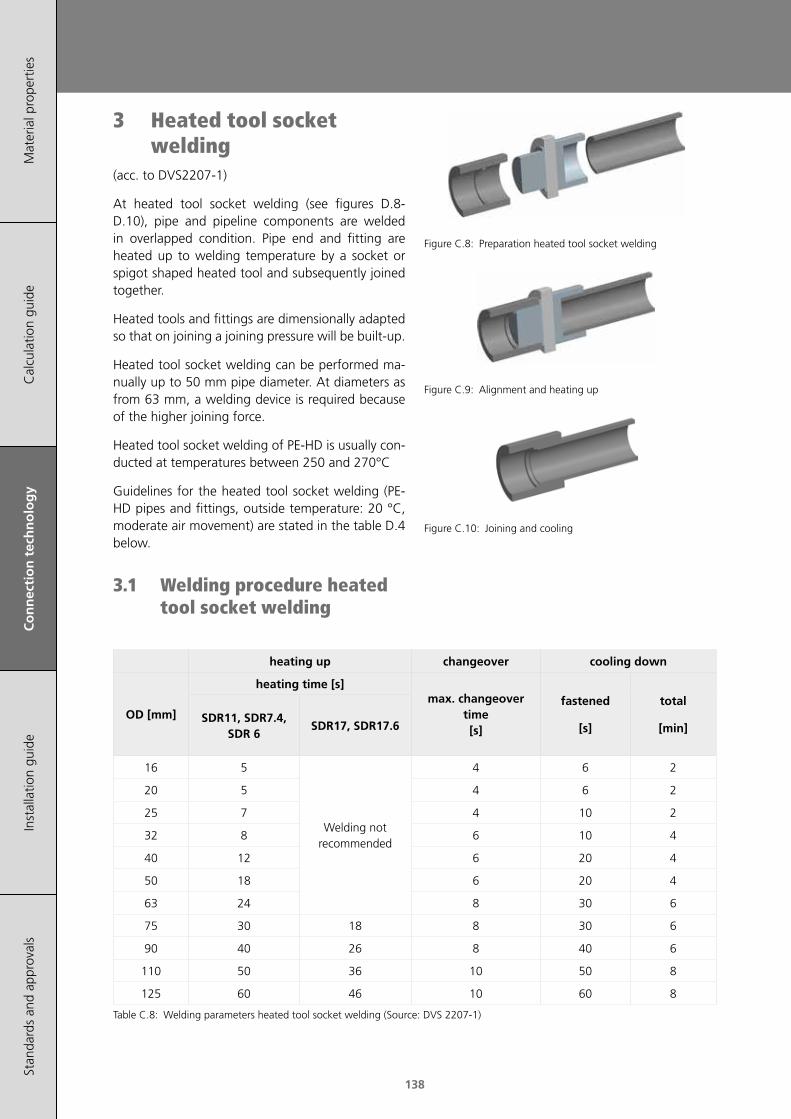
138
Mat
eria
l pro
pert
ies
Cal
cula
tion
guid
eC
on
nec
tio
n t
ech
no
log
yIn
stal
latio
n gu
ide
Stan
dard
s an
d ap
prov
als
3 Heated tool socket welding
(acc. to DVS2207-1)
At heated tool socket welding (see figures D.8-D.10), pipe and pipeline components are welded in overlapped condition. Pipe end and fitting are heated up to welding temperature by a socket or spigot shaped heated tool and subsequently joined together.
Heated tools and fittings are dimensionally adapted so that on joining a joining pressure will be built-up.
Heated tool socket welding can be performed ma-nually up to 50 mm pipe diameter. At diameters as from 63 mm, a welding device is required because of the higher joining force.
Heated tool socket welding of PE-HD is usually con-ducted at temperatures between 250 and 270°C
Guidelines for the heated tool socket welding (PE-HD pipes and fittings, outside temperature: 20 °C, moderate air movement) are stated in the table D.4 below.
3.1 Welding procedure heated tool socket welding
heating up changeover cooling down
OD [mm]
heating time [s]max. changeover
time [s]
fastened
[s]
total
[min]SDR11, SDR7.4,
SDR 6SDR17, SDR17.6
16 5
Welding not recommended
4 6 2
20 5 4 6 2
25 7 4 10 2
32 8 6 10 4
40 12 6 20 4
50 18 6 20 4
63 24 8 30 6
75 30 18 8 30 6
90 40 26 8 40 6
110 50 36 10 50 8
125 60 46 10 60 8
Table C.8: Welding parameters heated tool socket welding (Source: DVS 2207-1)
Figure C.8: Preparation heated tool socket welding
Figure C.9: Alignment and heating up
Figure C.10: Joining and cooling

139
Mat
eria
l pro
pert
ies
Cal
cula
tion
guid
eC
on
nec
tio
n t
ech
no
log
yIn
stal
latio
n gu
ide
Stan
dard
s an
d ap
prov
als
Connection technology
3.1.1 Preparation of welding area
• Ensure a stable position of the welding machine and check the welding equipment.
• If necessary, set up the tent / shelter.
• Clean the heating elements.
3.1.2 Preparation of pipes and fittings
• Cut the pipes and fittings rectangular and chamfer the inner edge with a knife.
• Chamfer the pipe end (table D.4) and remove the oxide layer by scraping the pipe end with a scraping tool. Keep scraping until the blades of the tool are flush with the pipe end.
pipe OD [mm]
pipe chamfer b [mm]
insert depth l [mm]
20
2
14
25 16
32 18
40 20
50 23
63
3
27
75 31
90 35
110 41
Table C.7: Required pipe chamfer and insert depth
3.1.3 Preparation welding procedure
• Prior to the start of the welding process, the welding temperature of the heated tool has to be checked. (start the welding procedure at least10 minutes after reaching the welding temperature).
• To prevent the heating element from contami-nation or damage, it has to be stored under a protective cover before and after the welding.
• To ensure an optimum welding connection the heated tool has to be cleaned with clean lint-free cloth before every welding operation.
3.1.4 Welding
• For the purpose of heating, fitting and pipe are pushed swiftly and axially onto the devices fit-ted on the heated tool and held until the stop at machine welding or until the mark at manual welding. Under no circumstances must the end of the pipe be pushed against the heater block.
• The heating-up time starts according to the time values in table D.5.
• After the heating time has elapsed, the fitting and pipe should be withdrawn sharply from the heated tool and pushed together immediately without any twisting until the stop or mark is met.
• At manual welding the joined components have to be kept fixed until the cooling time (fixed) elapses.
• The connection may be pressurised or handled only after cooling time is over.
3.1.5 Testing of welded joints
3.1.5.1 Visual test
Smooth welding joint on the complete circumfe-rence. The angular deviation of the pipe is not al-lowed.
3.1.5.2 Pressure test
A pressure test has to be conducted according to the standards (e.g. DVS 2210-1, supplement 2, DIN EN 805, DVGW 400-2 and chapter 7 respectively).

140
Mat
eria
l pro
pert
ies
Cal
cula
tion
guid
eC
on
nec
tio
n t
ech
no
log
yIn
stal
latio
n gu
ide
Stan
dard
s an
d ap
prov
als
4 Electro-fusion welding DIM 20-500mm monofilar
(acc. to DVS2207-1)
Electro-fusion (EF) fittings with monofilar welding system are used to weld the components using resistance wire (heating wire). The heating wire is completely embedded in the fitting.
This provides a smooth inner surface and allows an easy cleaning and insertion of the pipe ends/spigots. A (universal) welding machine provides the required power supply.
The required welding pressure results from the ten-sions caused by shrinkage of the fitting during the welding. This ensures an optimal welding result.
Special features of the process are a low voltage as well as a high automation level. Welding can be carried out on site even under difficult conditions (difficult access).
Figure C.11: Principle of the monofilar welding technique
A universal welding machine with a bar code reader and an automatic data logging should be used for the welding of the AGRU EF-fittings. Thus a simple handling and a traceability can be assured.
4.1 Bar codeA bar code contains all required welding parameters and can be read by all current welding machines. Agru ef-fittings have a label with a welding and a traceability codes attached.
The traceability code is used for the batch documen-tation. Both codes have diffenent colors for better differentiation. (see fig. D.12):
Figure C.12: Agru bar code label
welding code (white background)
position description
1-2 fitting
3-6 manufacturer
7-8 cooling time
9-11 dimension
12 energy input
13-14 voltage level
15-17 resistance
18 resistance tolerance range
19-21 welding time
22-23 energy correction value
24 check digit
traceability code (yellow background)
position description
1-4 manufacturer
5-6 fitting
7-9 dimension
10-15 serial number
16-17 production plant
18 SDR
19-22 material code
23 material condition
24 MRS
25 MFR
26 check digit

141
Mat
eria
l pro
pert
ies
Cal
cula
tion
guid
eC
on
nec
tio
n t
ech
no
log
yIn
stal
latio
n gu
ide
Stan
dard
s an
d ap
prov
als
Connection technology
4.2 General weldabilityPE 80, PE 100 und PE 100-RC can be welded together without any problems.
Attention: The pipe / EF-fitting with the lowest PN rating determines the PN rating of the entire pipeline (e.g. PN25 (SDR 7,4) pipes welded with PN16 (SDR11) EF-couper –> pipeline: PN16).
The weldability of the ef-fittings is tested and approved with following SDR classes:
EF-fitting
OD [mm]
weldable pipes/fittings
SDR 33 SDR 26 SDR 17,6 SDR 17 SDR 13,6 SDR 11 SDR 9 SDR 7,4
SDR
11 (E
F-fit
ting)
20 weldable with wall thicknesses from s=2,5mm to s= 3,5mm*
25 weldable with wall thicknesses from s=2,7mm to s= 3,8mm*
32 x x x x x
40 x x
50 x x
63 x x
75 x x
90 x x
110 x x
125 x x
140 x x
160 x x
180 x
200 x x
225 x x
250 x
280 x
315 x x x
355 x x x
400 x x x
450 x x x x
500 x x x x
SDR
17 (E
F-fit
ting)
90 x x x x x
110 x x x x
160 x x x x
200 x x x x
225 x x x x
250 x x x x
280 x x x x
315 x x x x
355 x x x x
400 x x x x
450 x x x x
500 x x x x
*thin-walled pipes must be welded using tubular stiffeners.
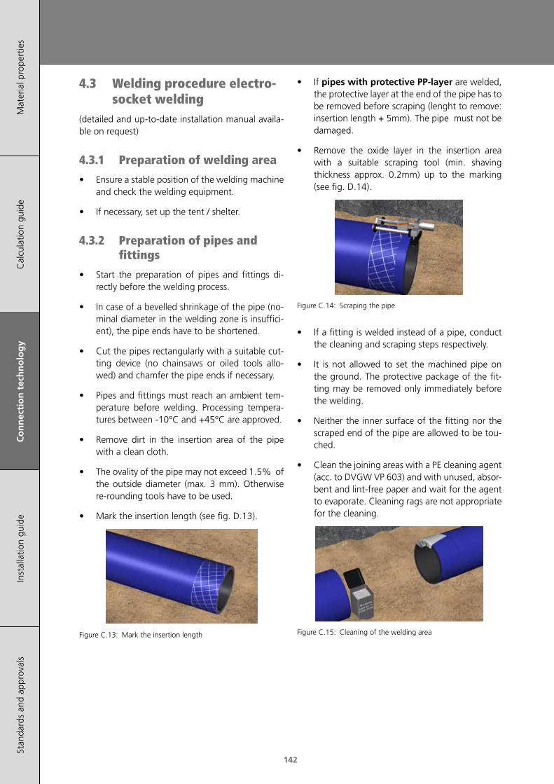
142
Mat
eria
l pro
pert
ies
Cal
cula
tion
guid
eC
on
nec
tio
n t
ech
no
log
yIn
stal
latio
n gu
ide
Stan
dard
s an
d ap
prov
als
4.3 Welding procedure electro-socket welding
(detailed and up-to-date installation manual availa-ble on request)
4.3.1 Preparation of welding area
• Ensure a stable position of the welding machine and check the welding equipment.
• If necessary, set up the tent / shelter.
4.3.2 Preparation of pipes and fittings
• Start the preparation of pipes and fittings di-rectly before the welding process.
• In case of a bevelled shrinkage of the pipe (no-minal diameter in the welding zone is insuffici-ent), the pipe ends have to be shortened.
• Cut the pipes rectangularly with a suitable cut-ting device (no chainsaws or oiled tools allo-wed) and chamfer the pipe ends if necessary.
• Pipes and fittings must reach an ambient tem-perature before welding. Processing tempera-tures between -10°C and +45°C are approved.
• Remove dirt in the insertion area of the pipe with a clean cloth.
• The ovality of the pipe may not exceed 1.5% of the outside diameter (max. 3 mm). Otherwise re-rounding tools have to be used.
• Mark the insertion length (see fig. D.13).
Figure C.13: Mark the insertion length
• If pipes with protective PP-layer are welded, the protective layer at the end of the pipe has to be removed before scraping (lenght to remove: insertion length + 5mm). The pipe must not be damaged.
• Remove the oxide layer in the insertion area with a suitable scraping tool (min. shaving thickness approx. 0.2mm) up to the marking (see fig. D.14).
Figure C.14: Scraping the pipe
• If a fitting is welded instead of a pipe, conduct the cleaning and scraping steps respectively.
• It is not allowed to set the machined pipe on the ground. The protective package of the fit-ting may be removed only immediately before the welding.
• Neither the inner surface of the fitting nor the scraped end of the pipe are allowed to be tou-ched.
• Clean the joining areas with a PE cleaning agent (acc. to DVGW VP 603) and with unused, absor-bent and lint-free paper and wait for the agent to evaporate. Cleaning rags are not appropriate for the cleaning.
Figure C.15: Cleaning of the welding area

143
Mat
eria
l pro
pert
ies
Cal
cula
tion
guid
eC
on
nec
tio
n t
ech
no
log
yIn
stal
latio
n gu
ide
Stan
dard
s an
d ap
prov
als
Connection technology
• Mark the insertion length again for the follow-up control.
• Insert the pipes/fitting ends into the EF-fitting up to the insertion mark (see fig. D.16).
• Clamp both welding components with a clam-ping device tension-free. The EF-fitting is sup-posed to be moved smoothly. The welding com-ponents must remain clamped during the entire welding process (incl. cooling time).
Figure C.16: Fixed welding components
• EF-fittings might be welded without using a clamping device if it is allowed by national regu-lations. The processing guidelines must accord to the DVS 2207-1 and to the AGRU guidelines. The welding components have to be tension-free even without clamping device.
4.3.3 Welding
• The welding machine is connected by a cable to the fitting to be welded. The cable has to be placed load-free
Figure C.17: Connecting the welding machine
• Input of the welding parameters with a scanner or a bar code stylus (fig D.40).
• Follow the instructions of the welding machine manual.
• If the welding process is interrupted (e.g. power failure) a single re-welding of the fitting is possi-ble. The joining area must cool down complete-ly (<35 °C) before the welding can be repeated.
4.3.4 Testing of welding joints
• Welding indicators show if the welding process has occured. The indicators don't prove the quality of the welding.
• Conduct the pressure test acc. to relevant stan-dards (e.g. DVS 2210-1, suppl. 2, DIN EN 805, DVGW-worksheet 400-2). Pressure test is only possible, after the welding connection is cooled down completely.
• Provide a welding protocol (handwritten or au-tomatic logging of the welding machine).
Installation animationelectrofusion couplers
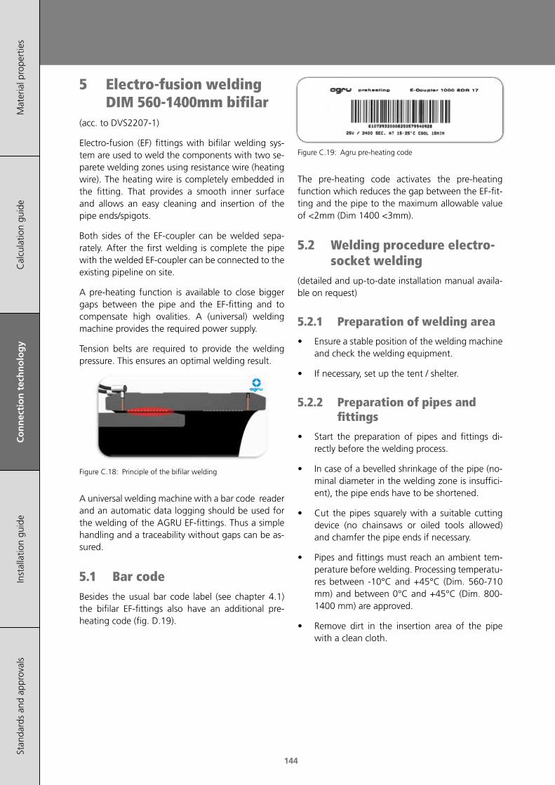
144
Mat
eria
l pro
pert
ies
Cal
cula
tion
guid
eC
on
nec
tio
n t
ech
no
log
yIn
stal
latio
n gu
ide
Stan
dard
s an
d ap
prov
als
5 Electro-fusion welding DIM 560-1400mm bifilar
(acc. to DVS2207-1)
Electro-fusion (EF) fittings with bifilar welding sys-tem are used to weld the components with two se-parete welding zones using resistance wire (heating wire). The heating wire is completely embedded in the fitting. That provides a smooth inner surface and allows an easy cleaning and insertion of the pipe ends/spigots.
Both sides of the EF-coupler can be welded sepa-rately. After the first welding is complete the pipe with the welded EF-coupler can be connected to the existing pipeline on site.
A pre-heating function is available to close bigger gaps between the pipe and the EF-fitting and to compensate high ovalities. A (universal) welding machine provides the required power supply.
Tension belts are required to provide the welding pressure. This ensures an optimal welding result.
Figure C.18: Principle of the bifilar welding
A universal welding machine with a bar code reader and an automatic data logging should be used for the welding of the AGRU EF-fittings. Thus a simple handling and a traceability without gaps can be as-sured.
5.1 Bar codeBesides the usual bar code label (see chapter 4.1) the bifilar EF-fittings also have an additional pre-heating code (fig. D.19).
Figure C.19: Agru pre-heating code
The pre-heating code activates the pre-heating function which reduces the gap between the EF-fit-ting and the pipe to the maximum allowable value of <2mm (Dim 1400 <3mm).
5.2 Welding procedure electro-socket welding
(detailed and up-to-date installation manual availa-ble on request)
5.2.1 Preparation of welding area
• Ensure a stable position of the welding machine and check the welding equipment.
• If necessary, set up the tent / shelter.
5.2.2 Preparation of pipes and fittings
• Start the preparation of pipes and fittings di-rectly before the welding process.
• In case of a bevelled shrinkage of the pipe (no-minal diameter in the welding zone is insuffici-ent), the pipe ends have to be shortened.
• Cut the pipes squarely with a suitable cutting device (no chainsaws or oiled tools allowed) and chamfer the pipe ends if necessary.
• Pipes and fittings must reach an ambient tem-perature before welding. Processing temperatu-res between -10°C and +45°C (Dim. 560-710 mm) and between 0°C and +45°C (Dim. 800-1400 mm) are approved.
• Remove dirt in the insertion area of the pipe with a clean cloth.

145
Mat
eria
l pro
pert
ies
Cal
cula
tion
guid
eC
on
nec
tio
n t
ech
no
log
yIn
stal
latio
n gu
ide
Stan
dard
s an
d ap
prov
als
Connection technology
• The ovality of the pipe may not exceed 1.5% of the outside diameter (max. 3 mm). Otherwise mechanically or hydraulically powered re-roun-ding tools have to be used. These are mounted onto the pipe at the end of the insertion depth.
Figure C.20: Diagram of a re-rounding clamps
• Mark the insertion length (insertion length = fit-ting length × 0.5).
• Remove the oxide layer in the insertion area with a suitable scraping tool up to the marking.
• Depending on the fit a single scraping of the pipe (min. 0.2 mm) can be already sufficient. Due to the big tolerance range of pipes it may be necessary to repeat the scraping of the pipe.
• In order to avoid multiple try-ons, a measuring of the diameter of the pipe is recommended prior to the scraping. Local bumps, which are detected at the checking of the annular gap, may be removed with a hand scraper. Take care to maintain a small annular gap during the pre-paration.
• Minimum diameter of the pipe = nominal diameter - 0.4mm
• Damages within the welding zone such as grooves or scratches are not permissible.
• If a fitting is welded instead of a pipe, conduct the cleaning and scraping steps respectively.
• Mark the insertion length again for the follow-up control.
• Clean the joining areas with a PE cleaning agent (acc. to DVGW VP 603) and with unused, absor-bent and lint-free paper and wait for the agent to evaporate. Cleaning rags are not appropriate for the cleaning.
Figure C.21: Cleaning of the welding area
5.2.3 Mounting the EF-fitting
• The protective package of the fitting may be removed only immediately before the welding. Neither the inner surface of the fitting nor the scraped end of the pipe are allowed to be tou-ched.
• In order to ease the mounting of the fitting, a chamfering of the pipe outside edge (5 mm × 45°) is helpfull. The inside edge of the pipe end may be chamfered. Remove the shavings from the pipe afterwards.
• Mind the position of the welding contacts and labels (pre-/welding code) for easy accessibility.
• The installation can be assisted by evenly dis-tributed blows with a soft-head hammer until the marked position is reached. Do not tilt the fitting during the mounting.
• Both welding components have to be aligned axially and tension-free. This can be reached by using a clamping system/support bar or by lay-ing something underneath the pipe/fitting.
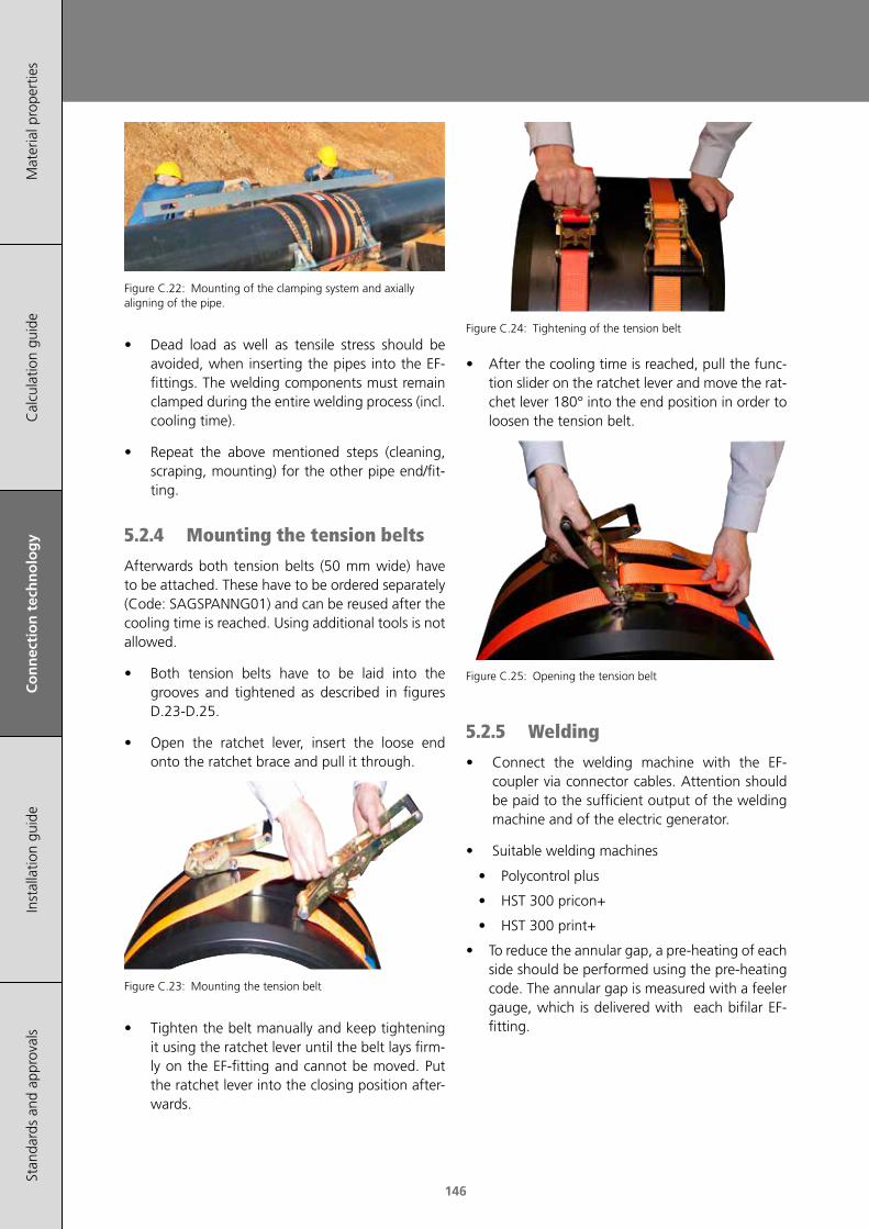
146
Mat
eria
l pro
pert
ies
Cal
cula
tion
guid
eC
on
nec
tio
n t
ech
no
log
yIn
stal
latio
n gu
ide
Stan
dard
s an
d ap
prov
als
Figure C.22: Mounting of the clamping system and axially aligning of the pipe.
• Dead load as well as tensile stress should be avoided, when inserting the pipes into the EF-fittings. The welding components must remain clamped during the entire welding process (incl. cooling time).
• Repeat the above mentioned steps (cleaning, scraping, mounting) for the other pipe end/fit-ting.
5.2.4 Mounting the tension belts
Afterwards both tension belts (50 mm wide) have to be attached. These have to be ordered separately (Code: SAGSPANNG01) and can be reused after the cooling time is reached. Using additional tools is not allowed.
• Both tension belts have to be laid into the grooves and tightened as described in figures D.23-D.25.
• Open the ratchet lever, insert the loose end onto the ratchet brace and pull it through.
Figure C.23: Mounting the tension belt
• Tighten the belt manually and keep tightening it using the ratchet lever until the belt lays firm-ly on the EF-fitting and cannot be moved. Put the ratchet lever into the closing position after-wards.
Figure C.24: Tightening of the tension belt
• After the cooling time is reached, pull the func-tion slider on the ratchet lever and move the rat-chet lever 180° into the end position in order to loosen the tension belt.
Figure C.25: Opening the tension belt
5.2.5 Welding
• Connect the welding machine with the EF-coupler via connector cables. Attention should be paid to the sufficient output of the welding machine and of the electric generator.
• Suitable welding machines
• Polycontrol plus
• HST 300 pricon+
• HST 300 print+
• To reduce the annular gap, a pre-heating of each side should be performed using the pre-heating code. The annular gap is measured with a feeler gauge, which is delivered with each bifilar EF-fitting.

147
Mat
eria
l pro
pert
ies
Cal
cula
tion
guid
eC
on
nec
tio
n t
ech
no
log
yIn
stal
latio
n gu
ide
Stan
dard
s an
d ap
prov
als
Connection technology
• After the pre-heating the annular gap of the first side of the EF-fitting has to be measured within the hold time. If the annular gap is okay, the welding of that side can be started. If the gap is too big, the pre-heating procedure has to be repeated.
Figure C.26: Measuring the annular gap with the feeler gauge
• Repeat the above mentioned steps (welding) for the other side of the EF-fitting.
• After the pre-heating the actual welding of the EF-fitting can be started. The welding parame-ters are input into the welding machine with a scanner or a bar code stylus.
• Follow the instructions of the welding machine manual.
• It is essentiall to wait for the cooling time to elapse.
• If the welding process is interrupted (e.g. power failure) a single re-welding of the fitting is possi-ble. The joining area must cool down complete-ly (<35 °C) before the welding can be repeated. Additionally the pre-heating and the annular gap testing have to be repeated.
5.2.6 Testing of welding joints
• Conduct the pressure test acc. to relevant stan-dards (e.g. DVS 2210-1, suppl. 2, DIN EN 805, DVGW-worksheet 400-2). Pressure test is only possible, after the welding connection is cooled down completely.
• Provide a welding protocol (handwritten or au-tomatic logging of the welding machine).
• After the cooling time is reached, the tension belts can be removed.
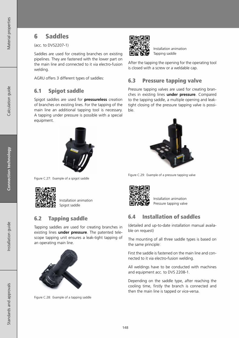
148
Mat
eria
l pro
pert
ies
Cal
cula
tion
guid
eC
on
nec
tio
n t
ech
no
log
yIn
stal
latio
n gu
ide
Stan
dard
s an
d ap
prov
als
6 Saddles(acc. to DVS2207-1)
Saddles are used for creating branches on existing pipelines. They are fastened with the lower part on the main line and connected to it via electro-fusion welding.
AGRU offers 3 different types of saddles:
6.1 Spigot saddleSpigot saddles are used for pressureless creation of branches on existing lines. For the tapping of the main line an additional tapping tool is necessary. A tapping under pressure is possible with a special equipment.
Figure C.27: Example of a spigot saddle
Installation animationSpigot saddle
6.2 Tapping saddleTapping saddles are used for creating branches in existing lines under pressure. The patented tele-scope tapping unit ensures a leak-tight tapping of an operating main line.
Figure C.28: Example of a tapping saddle
Installation animationTapping saddle
After the tapping the opening for the operating tool is closed with a screw or a weldable cap.
6.3 Pressure tapping valvePressure tapping valves are used for creating bran-ches in existing lines under pressure. Compared to the tapping saddle, a multiple opening and leak-tight closing of the pressure tapping valve is possi-ble.
Figure C.29: Example of a pressure tapping valve
Installation animationPressure tapping valve
6.4 Installation of saddles(detailed and up-to-date installation manual availa-ble on request)
The mounting of all three saddle types is based on the same principle:
First the saddle is fastened on the main line and con-nected to it via electro-fusion welding.
All weldings have to be conducted with machines and equipment acc. to DVS 2208-1.
Depending on the saddle type, after reaching the cooling time, firstly the branch is connected and then the main line is tapped or vice-versa.

149
Mat
eria
l pro
pert
ies
Cal
cula
tion
guid
eC
on
nec
tio
n t
ech
no
log
yIn
stal
latio
n gu
ide
Stan
dard
s an
d ap
prov
als
Connection technology
6.4.1 Installation spigot saddle
• Mark the saddle width on the pipe
• Dismantle the pipes with PP-protective layer in the welding area. Remove the oxide layer in the welding area between the marks with an appropriate scraping tool (shaving thickness ap-prox. 0.2 mm) (fig. A.30).
Figure C.30: Scraping of the pipe
• Take the saddle out of the packaging just before the welding.
• Do not touch the saddle / scraped pipe with your fingers to prevent contamination.
• Clean the joining areas with a PE cleaning agent (acc. to DVGW VP 603) and with unused, absor-bent and lint-free cloth and wait for the agent to evaporate. Cleaning rags are not appropriate for the cleaning.
• Put the saddle on the pipe and fix it with the lower part. Keep turning the screws in, until the upper and lower parts meet.
Figure C.31: Mounting the saddle
• Connect the welding machine to the fitting.
• Input of the welding parameters with a scanner or a bar code stylus (see fig A.32).
Figure C.32: Input of welding parameters
• Follow the instructions of the welding machine manual.
• If the welding process is interrupted (e.g. power failure) a single re-welding of the fitting is possi-ble. The joining area must cool down complete-ly (<35 °C) before the welding can be repeated.
• Welding indicators show if the welding process has occured. The indicators don't prove the quality of the welding.
• Conduct the pressure test acc. to relevant stan-dards (e.g. DVS 2210-1, suppl. 2, DIN EN 805, DVGW-worksheet 400-2). Pressure test is only possible, after the welding connection is cooled down completely.
• Provide a welding protocol (handwritten or au-tomatic logging of the welding machine).
• Tapping of the pipe pressureless or under pres-sure with a special equipment is only possible after the cooling time (>20 min) is over.

150
Mat
eria
l pro
pert
ies
Cal
cula
tion
guid
eC
on
nec
tio
n t
ech
no
log
yIn
stal
latio
n gu
ide
Stan
dard
s an
d ap
prov
als
6.4.2 Installation tapping saddle
• Mark the saddle width on the pipe
• Dismantle the pipes with PP-protective layer in the welding area. Remove the oxide layer in the welding area between the marks with an ap-propriate scraping tool (shaving thickness ca. 0.2 mm) (fig. A.34).
Figure C.33: Scraping of the pipe
• Take the saddle out of the packaging just before the welding.
• Do not touch the saddle / scraped pipe with your fingers to prevent contamination.
• Clean the joining areas with a PE cleaning agent (acc. to DVGW VP 603) and with unused, absor-bent and lint-free cloth and wait for the agent to evaporate. Cleaning rags are not appropriate for the cleaning.
• Put the saddle on the pipe and fix it with the lower part. Keep turning the screws in, until the upper and lower parts meet (fig. A.35).
Figure C.34: Mounting the saddle
• Connect the welding machine to the fitting.
Figure C.35: Input of welding parameters
• Input of the welding parameters with a scanner or a bar code stylus (see fig A.32).
• Follow the instructions of the welding machine manual.
• Tapping of the main pipe is only possible after the cooling time (>20 min) is over.
• If the welding process is interrupted (e.g. power failure) a single re-welding of the fitting is possi-ble. The joining area must cool down complete-ly (<35 °C) before the welding can be repeated.
• Welding indicators show if the welding process has occured. The indicators don't prove the quality of the welding.
• Conduct the pressure test acc. to relevant stan-dards (e.g. DVS 2210-1, suppl. 2, DIN EN 805, DVGW-worksheet 400-2). Pressure test is only possible, after the welding connection is cooled down completely.
• Provide a welding protocol (handwritten or au-tomatic logging of the welding machine).
• Tapping of the pipe is only possible after the cooling time (>20 min) is over. The branch must be already connected.
• Insert the tapping key into the saddle and turn it until the stop is reached. Turning the tapping key back releases the connection (Caution: ma-ximum moment at the end stop: 1 Nm).
Figure C.36: Tapping of the pipe
• Close the tapping opening with a screw or wel-ding cap.
Figure C.37: Close of the pipe

151
Mat
eria
l pro
pert
ies
Cal
cula
tion
guid
eC
on
nec
tio
n t
ech
no
log
yIn
stal
latio
n gu
ide
Stan
dard
s an
d ap
prov
als
Connection technology
6.4.3 Installation pressure tapping valve DAV
• Mark the width of the valve on the pipe
• Dismantle the pipes with PP-protective layer in the welding area. Remove the oxide layer in the welding area between the marks with an ap-propriate scraping tool (shaving thickness ca. 0.2 mm) (fig. A.38).
Figure C.38: Scraping of the pipe
• Take the valve out of the packaging just before the welding.
• Do not touch the valve / scraped pipe with your fingers to prevent contamination.
• Clean the joining areas with a PE cleaning agent (acc. to DVGW VP 603) with unused, absorbent and lint-free cloth and wait for the agent to evaporate. Cleaning rags are not appropriate for the cleaning.
• Put the valve on the pipe and fix it by locking the top part with the bottom part. To provide the necessary welding pressure the pre-moun-ted screws have to be screwed into the integra-ted nuts in the bottom part. It has to be ensured that the gap between the top- and bottom part is closed.
Figure C.39: Mounting the pressure tapping valve
• Connect the welding machine to the valve.
Figure C.40: Input of welding parameters
• Tapping of the pipe is only possible after the cooling time (>20 min) is over. The branch must be already connected.
• Insert the tapping key into the saddle and turn it until the stop is reached. Turning the tapping key back releases the connection. To fix the val-ve position the spindle has to be turned with with normal manual force against the upper/lower stopper.
Figure C.41: Tapping of the pipe

152
Mat
eria
l pro
pert
ies
Cal
cula
tion
guid
eC
on
nec
tio
n t
ech
no
log
yIn
stal
latio
n gu
ide
Stan
dard
s an
d ap
prov
als
6.5 Detachable joints• It is recommended to coat the bolts for the flan-
ge connection with molybdenum sulfide grease to ensure a smooth operation, even during a long operation period.
• When choosing a seal material, consider its thermal and chemical suitability.
• The bolts shouldn‘t protrude further than two to three thread lengths after the nut.
• Washers have to be placed at the bolt head and also at the nut.
• Before applying the bolt initial prestress, the sealing faces have to be aligned parallel to each other and fit tight to the sealing.
• Adjusting the position of the sealing faces by means of bolt pretensioning using a spanner is not permissible
• The required bolt-tightening torque depends on the shape and the selected material of the seal (Shore A hardness) as well as on the friction in the screw thread and on the nut contact face (average friction coefficient of 0.15 can be ex-pected).
• The connecting bolts have to be screwed dia-gonally by means of a torque key (torque values see table D.8).
• The bolting torque must induce a certain amount of compressive stress on the elasto-meric seal (≥0,5 N/mm2). Below this minimum compressive stress a leak may occur. Otherwise, an excessive compressive stress may cause da-mage and deformation of the seal area (seal, stub end, backing ring, etc.).
• Flange connections which are exposed to alter-nating stresses and heavy impacts, have to be checked within prescribed maintenance inter-vals and retightened if necessary.
shape of the seal
recommended operational limits flange- /stub
end designpressure [bar]
temp. [°C]
flat ring up to 10* bis 40with sealing
grooves
profiled flat ring
up to 16 no limitswith / w/o
sealing grooves
*up to max. DN>150, max. 6bar
Table C.9: Flat seal selection criteria (Source: DVS 2210-1 suppl. 3)
Nominal width Thickness s [mm]
Up to d90 mm / DN 80 min. 2
≥ d110 mm / DN 100 min. 3
Table C.10: Minimal thickness of flat seals (Source: DVS 2210-1 suppl. 3)
Bolting torque [Nm]
DNflat ring up to
10 barprofiled ring up to 16 bar
15 15 15
20 15 15
25 15 15
32 20 15
40 30 15
50 35 20
65 40 25
80 40 25
100 40 30
125 50 35
150 60 40
200 70* 50
250 80* 55
300 100* 60
350 100* 70
400 120* 80
Table C.11: Guidelines bolting torque (Shore-Hardness 80° acc. to DVS 2210-1 suppl. 3) * allowable operating pressure ≤ 6 bar
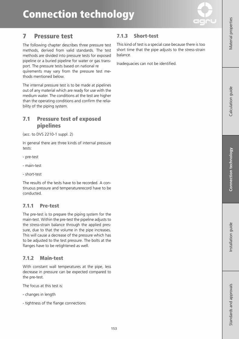
153
Mat
eria
l pro
pert
ies
Cal
cula
tion
guid
eC
on
nec
tio
n t
ech
no
log
yIn
stal
latio
n gu
ide
Stan
dard
s an
d ap
prov
als
Connection technology
7 Pressure testThe following chapter describes three pressure test methods, derived from valid standards. The test methods are divided into pressure tests for exposed pipeline or a buried pipeline for water or gas trans-port. The pressure tests based on national re quirements may vary from the pressure test me-thods mentioned below.
The internal pressure test is to be made at pipelines out of any material which are ready for use with the medium water. The conditions at the test are higher than the operating conditions and confirm the relia-bility of the piping system.
7.1 Pressure test of exposed pipelines
(acc. to DVS 2210-1 suppl. 2)
In general there are three kinds of internal pressure tests:
- pre-test
- main-test
- short-test
The results of the tests have to be recorded. A con-tinuous pressure and temperaturerecord have to be conducted.
7.1.1 Pre-test
The pre-test is to prepare the piping system for the main-test. Within the pre-test the pipeline adjusts to the stress-strain balance through the applied pres-sure, due to that the volume in the pipe increases. This will cause a decrease of the pressure which has to be adjusted to the test pressure. The bolts at the flanges have to be retightened as well.
7.1.2 Main-test
With constant wall temperatures at the pipe, less decrease in pressure can be expected compared to the pre-test.
The focus at this test is:
- changes in length
- tightness of the flange connections
7.1.3 Short-test
This kind of test is a special case because there is too short time that the pipe adjusts to the stress-strain balance.
Inadequacies can not be identified.
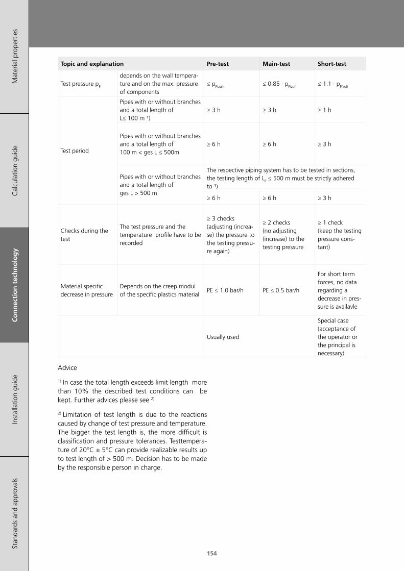
154
Mat
eria
l pro
pert
ies
Cal
cula
tion
guid
eC
on
nec
tio
n t
ech
no
log
yIn
stal
latio
n gu
ide
Stan
dard
s an
d ap
prov
als
Topic and explanation Pre-test Main-test Short-test
Test pressure pP
depends on the wall tempera-ture and on the max. pressure of components
≤ pP(zul) ≤ 0.85 · pP(zul) ≤ 1.1 · pP(zul)
Test period
Pipes with or without branches and a total length of L≤ 100 m ¹)
≥ 3 h ≥ 3 h ≥ 1 h
Pipes with or without branches and a total length of 100 m < ges L ≤ 500m
≥ 6 h ≥ 6 h ≥ 3 h
Pipes with or without branches and a total length of ges L > 500 m
The respective piping system has to be tested in sections, the testing length of LP ≤ 500 m must be strictly adhered to ¹)
≥ 6 h ≥ 6 h ≥ 3 h
Checks during the test
The test pressure and the temperature profile have to be recorded
≥ 3 checks (adjusting (increa-se) the pressure to the testing pressu-re again)
≥ 2 checks (no adjusting (increase) to the testing pressure
≥ 1 check (keep the testing pressure cons-tant)
Material specific decrease in pressure
Depends on the creep modul of the specific plastics material
PE ≤ 1.0 bar/h PE ≤ 0.5 bar/h
For short term forces, no data regarding a decrease in pres-sure is availavle
Usually used
Special case (acceptance of the operator or the principal is necessary)
Advice
1) In case the total length exceeds limit length more than 10% the described test conditions can be kept. Further advices please see 2)
2) Limitation of test length is due to the reactions caused by change of test pressure and temperature. The bigger the test length is, the more difficult is classification and pressure tolerances. Testtempera-ture of 20°C ± 5°C can provide realizable results up to test length of > 500 m. Decision has to be made by the responsible person in charge.

155
Mat
eria
l pro
pert
ies
Cal
cula
tion
guid
eC
on
nec
tio
n t
ech
no
log
yIn
stal
latio
n gu
ide
Stan
dard
s an
d ap
prov
als
Connection technology
7.1.4 Guidelines for pressure test of unburied piping systems
Prior to the pre-test, the air inside the pipe has to be removed. Therefore de-aeration points have to be set on the highest point of the pipe which have to be in open position when filling the pipe.
Filling of the pipe
The medium for filling is water.
The origin of the filling has to be the lowest point of the pipe. When setting the fill quantity per time unit it has to be considered that the air can escape safely at the de-aeration points.
If the pipeline has more than one lowest point, it may be necessary to fill the pipe in sections.
The time between filling and testing the pipe has to be long enough for the de-aeration (approximate time > 6 … 12h; it depends on the dimension of the pipe).
At pipelines bigger than DN 150 which do not have a peak or just have a very low gradient it may be necessary to use a pipeline pig to remove the remai-ning air in the pipe.
Reference values for the filling rate are given in Tab-le E.1
Figure C.42: Pressure increase time
DN V [l/s]
≤80 0.15
100 0.3
150 0.7
200 1.5
250 2.0
300 3.0
400 6.0
500 9.0
Table C.12: Reference values for filling the line
Applying the testing pressure
When applying the test pressure it has to be con-sidered that the increase of the pressure does not causes any water hammers.
Figure E.1 contains guide values
Advice:
At pipelines which contain components with a smal-ler maximum operating pressure compared to the pipe, the maximum applicable test pressure has to be in accordance with the manufacturer.
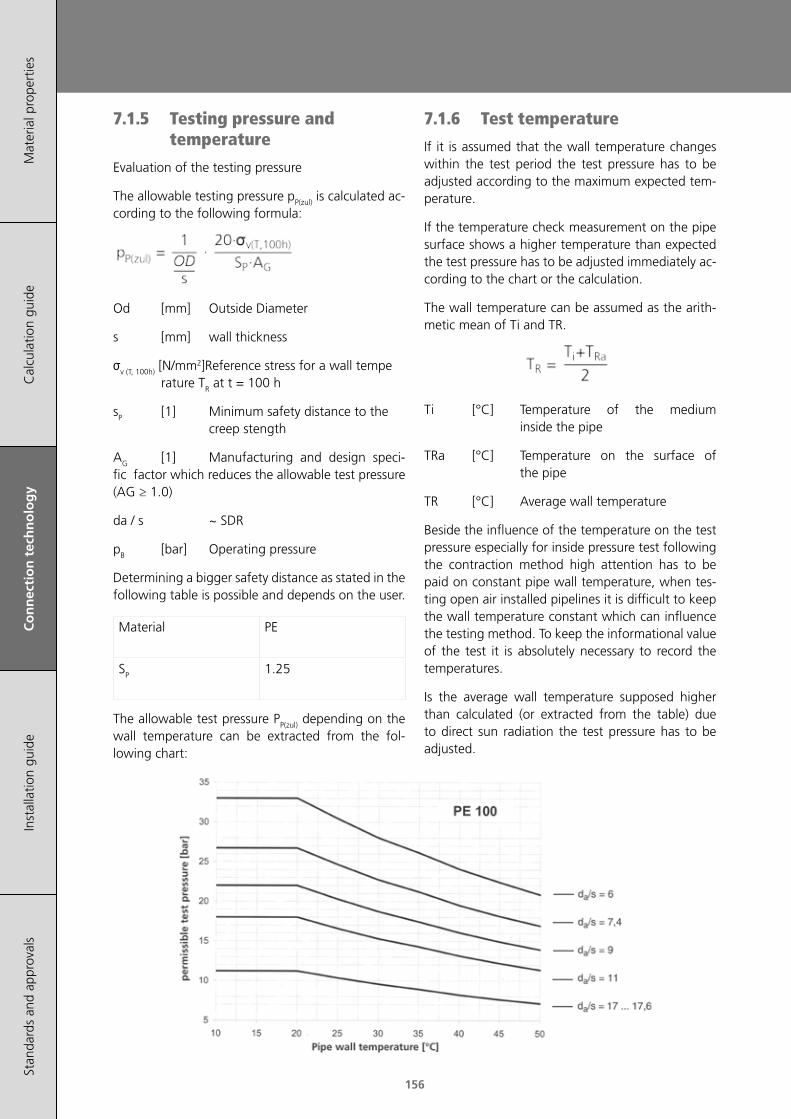
156
Mat
eria
l pro
pert
ies
Cal
cula
tion
guid
eC
on
nec
tio
n t
ech
no
log
yIn
stal
latio
n gu
ide
Stan
dard
s an
d ap
prov
als
7.1.5 Testing pressure and temperature
Evaluation of the testing pressure
The allowable testing pressure pP(zul) is calculated ac-cording to the following formula:
Od [mm] Outside Diameter
s [mm] wall thickness
σv (T, 100h) [N/mm2]Reference stress for a wall tempe rature TR at t = 100 h
sP [1] Minimum safety distance to the creep stength
AG [1] Manufacturing and design speci-fic factor which reduces the allowable test pressure (AG ≥ 1.0)
da / s ~ SDR
pB [bar] Operating pressure
Determining a bigger safety distance as stated in the following table is possible and depends on the user.
Material PE
SP 1.25
The allowable test pressure PP(zul) depending on the wall temperature can be extracted from the fol-lowing chart:
7.1.6 Test temperature
If it is assumed that the wall temperature changes within the test period the test pressure has to be adjusted according to the maximum expected tem-perature.
If the temperature check measurement on the pipe surface shows a higher temperature than expected the test pressure has to be adjusted immediately ac-cording to the chart or the calculation.
The wall temperature can be assumed as the arith-metic mean of Ti and TR.
Ti [°C] Temperature of the medium inside the pipe
TRa [°C] Temperature on the surface of the pipe
TR [°C] Average wall temperature
Beside the influence of the temperature on the test pressure especially for inside pressure test following the contraction method high attention has to be paid on constant pipe wall temperature, when tes-ting open air installed pipelines it is difficult to keep the wall temperature constant which can influence the testing method. To keep the informational value of the test it is absolutely necessary to record the temperatures.
Is the average wall temperature supposed higher than calculated (or extracted from the table) due to direct sun radiation the test pressure has to be adjusted.

157
Mat
eria
l pro
pert
ies
Cal
cula
tion
guid
eC
on
nec
tio
n t
ech
no
log
yIn
stal
latio
n gu
ide
Stan
dard
s an
d ap
prov
als
Connection technology
The measuring respectively the recording of the temperature in the inside of the pipeline (tempera-ture of the test medium) demands the assembly of a gauge connection at the most disadvantageous point of the piping system. In case that it is ensured by proper arrangements, that the temperature of the pipe wall is never exceeding a pre-defined maxi-mum value, it is not necessary to make the measu-rement of the medium temperature.
7.2 Guidelines for pressure test of buried water piping systems
Pressure test on the basis of ÖVGW W 101.
Each installed water pipeline has to be tested with a water pressure test to ensure the leak tightness of the pipeline and its components. As a test medium potable water should be used.
7.2.1 Filling and checking
The filling of the pipeline with clean water should be conducted with open air valves and adequate ven-ting. Calibration of the testing equipment should be carried out, before the equipment is connected to the pipe and the pressure test is started. During the test all venting devices should be closed.
7.2.2 Preparation pressure test
To prevent the pipeline from moving, it should be covered with enough back-fill material before the pressure test. The joints may be left uncovered. The anchors and the bearings must verifiably withstand the forces caused by the test pressure. The test should be conducted either on the complete pipe-line or in sections. When the pipeline is filled, the system test pressure (STP) must be reached at the lowest part of the pipeline. At the same time the system working pressure (MDP) must be reached at least at the highest point of each testing section. Before the pressure test the pipe has to be cleaned from any kind of contamination and has to be ven-tilated.
7.2.3 Minimising the temperature influence
High temperatures (or temperature fluctuation) on the pipe surface can lead to shorter lifetime or to false pressure test results.
To reduce the temperature influence following mea-sures are recommended during the pressure test:
• The water for the pressure test should be as cold as possible
• The exposed areas of the pipeline should be covered (shaded) during the test to prevent the pipe from heating up
• Keep the pipe wall temperatures between 2 and 20 °C and control the temperature regu-larly. The pressure test should be performed during moderate outside temperatures (in summer e.g. early in the morning).
• If the temperature values cannot be kept below 20 °C, the test pressure STP can be lowered as an exception to the maximum operating pressure MDP after a consultation with the planning engineer. The test section of the pipe should be continuously horizontal.
7.2.4 Test pressure
The system test pressure (STP) can be calculated with following formula by taking the highest system working pressure MDP into account:
By considering the pressure surge:
By not considering the pressure surge:
or
The lower of the two values is valid.
The pressure surge should be calculated with ap-propriate basic equations and assumptions of the engineer (worst case).
The testing equipment should be connected to the pipeline at its the lowest part.
For the calculation of short pipe sections and branch lines ≤ DN 80 and shorter than 100 m, the operating pressure can be assumed as system working pressu-re, if not otherwise specified.

158
Mat
eria
l pro
pert
ies
Cal
cula
tion
guid
eC
on
nec
tio
n t
ech
no
log
yIn
stal
latio
n gu
ide
Stan
dard
s an
d ap
prov
als
7.2.5 Types of pressure tests
The type of pressure test is determined depending on the type of the pipe and the material. The pres-sure test can consist of up to three parts:
• Pressure pre-test
• Integrated pressure loss test
• Main pressure test
7.2.6 Pressure pre-test
The pressure pre-test is carried out to avoid incorrect test results during the main pressure test. During the pre-test following steps are carried out:
• Relaxation phase (min. 1h) after the purging and venting of the pipeline. In the process the air must not get into the test sections.
• Continuous pressure increase (within 10 min) to the system pressure (STP) and subsequent holding of the pressure (30 min). During that period the pipeline should be inspected for leakages.
• Wait the rest period (1h) without re-pressurising and measure the residual pressure. If the pres-sure drop is higher than 30% of the STP, then the pressure test has to stopped to search for the cause of the failure. The rerun of the test is only possible 1h after relaxation phase at the earliest.
• When the pre-test is completed successfully, the main pressure test can be started.
7.2.7 Integrated pressure loss test
The pressure loss test is used to determine the resi-dual air volume in the pipeline. It allows to improve the precision of the main pressure test. During the pressure loss test the following steps are performed:
• Rapid pressure reduction (Δp: 10 – 15% of STP) by draining the water
• Measuring the volume of the drained water
• Calculating the allowable loss of water ΔVmax according to the following equation:
ΔVmax allowable loss of water [l]
V volume test section [l]
Δp measured pressure drop [kPa]
Ew compressive modulus water [kPa]
D inner diameter of the pipe [m]
e wall thickness of the pipe [m]
Er Young's Modulus pipe wall in circumferen tial direction [kPa]
1,2 factor: allowable amount of air before the main pressure test
• Checking if ΔV > ΔVmax. If ΔV is higher, the pres-sure test has to be stopped and repeated after the relaxation phase.
7.2.8 Main pressure test
The integrated pressure loss test interrupts the vis-coelastic expansion of the pipe and leads to a con-traction of the pipeline.
The resulting pressure rise is monitored and recor-ded in the period of 30 minutes. If the pressure cur-ve doesn't drop during the monitoring period, the main pressure test is considered as passed.
A drop of the pressure curve indicates a leakage in the pipeline.
When uncertainty exists, the test duration can be extended to 90 minutes. In doing so the pressure drop cannot exceed 25 kPa, otherwise the main pressure test is considered as failed.
The repeat of the main pressure test is only possible if the complete test process (+1h relaxation phase) is repeated.
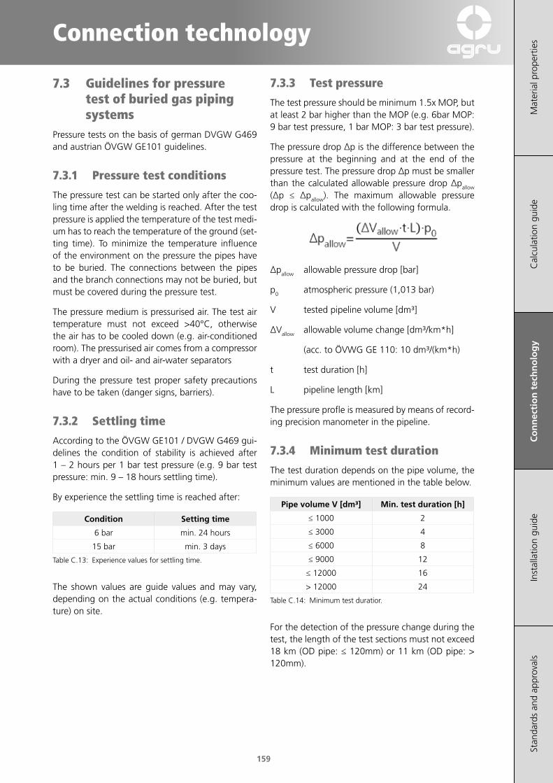
159
Mat
eria
l pro
pert
ies
Cal
cula
tion
guid
eC
on
nec
tio
n t
ech
no
log
yIn
stal
latio
n gu
ide
Stan
dard
s an
d ap
prov
als
Connection technology
7.3 Guidelines for pressure test of buried gas piping systems
Pressure tests on the basis of german DVGW G469 and austrian ÖVGW GE101 guidelines.
7.3.1 Pressure test conditions
The pressure test can be started only after the coo-ling time after the welding is reached. After the test pressure is applied the temperature of the test medi-um has to reach the temperature of the ground (set-ting time). To minimize the temperature influence of the environment on the pressure the pipes have to be buried. The connections between the pipes and the branch connections may not be buried, but must be covered during the pressure test.
The pressure medium is pressurised air. The test air temperature must not exceed >40°C, otherwise the air has to be cooled down (e.g. air-conditioned room). The pressurised air comes from a compressor with a dryer and oil- and air-water separators
During the pressure test proper safety precautions have to be taken (danger signs, barriers).
7.3.2 Settling time
According to the ÖVGW GE101 / DVGW G469 gui-delines the condition of stability is achieved after 1 – 2 hours per 1 bar test pressure (e.g. 9 bar test pressure: min. 9 – 18 hours settling time).
By experience the settling time is reached after:
Condition Setting time
6 bar min. 24 hours
15 bar min. 3 days
Table C.13: Experience values for settling time.
The shown values are guide values and may vary, depending on the actual conditions (e.g. tempera-ture) on site.
7.3.3 Test pressure
The test pressure should be minimum 1.5x MOP, but at least 2 bar higher than the MOP (e.g. 6bar MOP: 9 bar test pressure, 1 bar MOP: 3 bar test pressure).
The pressure drop Δp is the difference between the pressure at the beginning and at the end of the pressure test. The pressure drop Δp must be smaller than the calculated allowable pressure drop Δpallow (Δp ≤ Δpallow). The maximum allowable pressure drop is calculated with the following formula.
Δpallow allowable pressure drop [bar]
p0 atmospheric pressure (1,013 bar)
V tested pipeline volume [dm³]
ΔVallow allowable volume change [dm³/km*h]
(acc. to ÖVWG GE 110: 10 dm³/(km*h)
t test duration [h]
L pipeline length [km]
The pressure profle is measured by means of record-ing precision manometer in the pipeline.
7.3.4 Minimum test duration
The test duration depends on the pipe volume, the minimum values are mentioned in the table below.
Pipe volume V [dm³] Min. test duration [h]
≤ 1000 2
≤ 3000 4
≤ 6000 8
≤ 9000 12
≤ 12000 16
> 12000 24
Table C.14: Minimum test duratior.
For the detection of the pressure change during the test, the length of the test sections must not exceed 18 km (OD pipe: ≤ 120mm) or 11 km (OD pipe: > 120mm).

160
Mat
eria
l pro
pert
ies
Cal
cula
tion
guid
eC
on
nec
tio
n t
ech
no
log
yIn
stal
latio
n gu
ide
Stan
dard
s an
d ap
prov
als
161
Installation guide
Mat
eria
l pro
pert
ies
Cal
cula
tion
guid
eC
onne
ctio
n te
chno
logy
Inst
alla
tio
n g
uid
eSt
anda
rds
and
appr
oval
s
161
Installation guide
1 Transport / Handling / Storage 163
2 Installation 164
3 Product-specific characteristics for relining 171
4 Machining 173

162
Mat
eria
l pro
pert
ies
Cal
cula
tion
guid
eC
onne
ctio
n te
cahn
olog
yIn
stal
lati
on
gu
ide
Stan
dard
s an
d ap
prov
als
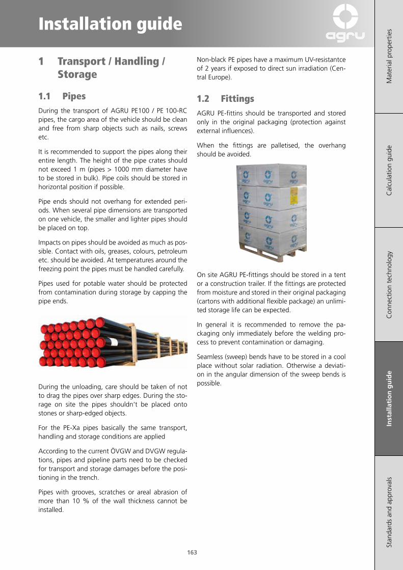
163
Installation guide
Mat
eria
l pro
pert
ies
Cal
cula
tion
guid
eC
onne
ctio
n te
chno
logy
Inst
alla
tio
n g
uid
eSt
anda
rds
and
appr
oval
s
1 Transport / Handling / Storage
1.1 PipesDuring the transport of AGRU PE100 / PE 100‑RC pipes, the cargo area of the vehicle should be clean and free from sharp objects such as nails, screws etc.
It is recommended to support the pipes along their entire length. The height of the pipe crates should not exceed 1 m (pipes > 1000 mm diameter have to be stored in bulk). Pipe coils should be stored in horizontal position if possible.
Pipe ends should not overhang for extended peri‑ods. When several pipe dimensions are transported on one vehicle, the smaller and lighter pipes should be placed on top.
Impacts on pipes should be avoided as much as pos‑sible. Contact with oils, greases, colours, petroleum etc. should be avoided. At temperatures around the freezing point the pipes must be handled carefully.
Pipes used for potable water should be protected from contamination during storage by capping the pipe ends.
During the unloading, care should be taken of not to drag the pipes over sharp edges. During the sto‑rage on site the pipes shouldn‘t be placed onto stones or sharp‑edged objects.
For the PE‑Xa pipes basically the same transport, handling and storage conditions are applied
According to the current ÖVGW and DVGW regula‑tions, pipes and pipeline parts need to be checked for transport and storage damages before the posi‑tioning in the trench.
Pipes with grooves, scratches or areal abrasion of more than 10 % of the wall thickness cannot be installed.
Non‑black PE pipes have a maximum UV‑resistantce of 2 years if exposed to direct sun irradiation (Cen‑tral Europe).
1.2 FittingsAGRU PE‑fittins should be transported and stored only in the original packaging (protection against external influences).
When the fittings are palletised, the overhang should be avoided.
On site AGRU PE‑fittings should be stored in a tent or a construction trailer. If the fittings are protected from moisture and stored in their original packaging (cartons with additional flexible package) an unlimi‑ted storage life can be expected.
In general it is recommended to remove the pa‑ckaging only immediately before the welding pro‑cess to prevent contamination or damaging.
Seamless (sweep) bends have to be stored in a cool place without solar radiation. Otherwise a deviati‑on in the angular dimension of the sweep bends is possible.
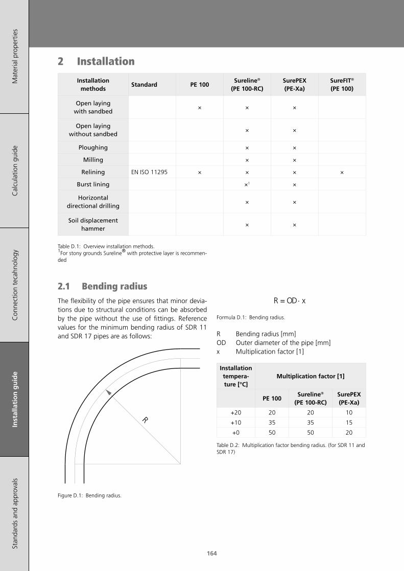
164
Mat
eria
l pro
pert
ies
Cal
cula
tion
guid
eC
onne
ctio
n te
cahn
olog
yIn
stal
lati
on
gu
ide
Stan
dard
s an
d ap
prov
als
2 Installation
Installation methods
Standard PE 100Sureline®
(PE 100‑RC)SurePEX (PE‑Xa)
SureFIT® (PE 100)
Open laying with sandbed
× × ×
Open laying without sandbed
× ×
Ploughing × ×
Milling × ×
Relining EN ISO 11295 × × × ×
Burst lining ×1 ×
Horizontal directional drilling
× ×
Soil displacement hammer
× ×
Table D.1: Overview installation methods. 1For stony grounds Sureline® with protective layer is recommen‑ded
2.1 Bending radiusThe flexibility of the pipe ensures that minor devia‑tions due to structural conditions can be absorbed by the pipe without the use of fittings. Reference values for the minimum bending radius of SDR 11 and SDR 17 pipes are as follows:
R
Figure D.1: Bending radius.
⋅ xODR =
Formula D.1: Bending radius.
R Bending radius [mm]OD Outer diameter of the pipe [mm]x Multiplication factor [1]
Installation tempera‑ture [°C]
Multiplication factor [1]
PE 100Sureline®
(PE 100‑RC)SurePEX (PE‑Xa)
+20 20 20 10
+10 35 35 15
+0 50 50 20
Table D.2: Multiplication factor bending radius. (for SDR 11 and SDR 17)

165
Installation guide
Mat
eria
l pro
pert
ies
Cal
cula
tion
guid
eC
onne
ctio
n te
chno
logy
Inst
alla
tio
n g
uid
eSt
anda
rds
and
appr
oval
s
2.2 Open trench installationFor the construction of pipe trenches and the ins‑tallation of the pipes, corresponding national and regional regulations have to be taken into account.
Generally changes in direction are realised by me‑ans of fittings (e.g.: bends, elbows and tees) whe‑reas the fittings and pipes are welded together (see chapter D). For big pipe dimensions the welding outside the trench has to be aimed in order to make work easier. For butt welding of big dimensions it is recommended to install the welding machine stati‑onary and continue to pull the welded pipe sections after the welding.
For smaller pipes, which are laid along the trench or when using electrofusion welding, the welding machine can be transported to the welding spot. For cross‑country installations a detection cable should be installed with the pipe in order to detect the pipeline easier in the future.
The following influencing factors on the installation technique and ‑depth have to be considered:
• Depth of frost or heat penetration (local con‑ditions)
• Flow rate, pressure and temperature of the me‑dia in the pipeline
• Insulation of the pipeline
• Traffic and soil loads
• Soil type, soil moisture and the surface condi‑tion
• Crossing lines
A structural analysis considering all influencing factors should be performed before each ins‑tallation.
For this purpose acknowledged calculation gui‑delines (ÖNORM B5012, ATV 127) have to be used.
2.2.1 Open trench installation with sand bed
The most established installation technique is cur‑rently the open trench installation with sand bed. For the installation the trench should be at least 40 cm wider than the pipe diameter. The trench depth should be excavated considering national standards. In doing so the crown of the pipe should be located underneath the depth of frost (especially important for water application). The trench bottom should be planar, stable and free of stones. A bedding layer of at least 10 cm (rocky ground: 15 cm) should be placed on the trench bottom. The pipeline should be lowered into the trench carefully. Additionally an all‑side cover have to be created (at least 10 cm) to avoid scratches and point‑loads.
Figure D.2: Diagram of a trench
a. Backfillexcavated material may be
reused
b. Cover
min. 10 cm around the pipe
c. Side bedding layer
d. Upper bedding layer
e. Lower bedding layer
Table D.3: Guidelines bedding/backfill

166
Mat
eria
l pro
pert
ies
Cal
cula
tion
guid
eC
onne
ctio
n te
cahn
olog
yIn
stal
lati
on
gu
ide
Stan
dard
s an
d ap
prov
als
2.2.2 Calculation of buried piping systems
A stress and deformation proof according to ATV, instruction sheet A 127, has to be furnished for bu‑ried piping systems (e. g. drainage channels). But there can also serve other basis for calculation, such as OEVGW (guideline G 52) or results of research projects.
There is a software program for the surcharge calcu‑lation according to ATV 127 at disposal in our tech‑nical engineering department in order to furnish the demanded proof. Please fill in the following questi‑onnaire as completely as possible. We will promptly prepare a corresponding statics after receipt of the questionnauire.
159159159159159
Mat
eria
l P
rope
rtie
sIn
stal
latio
n G
uide
lines
Cal
cula
tion
Gui
delin
esC
onne
ctio
n M
etho
dsD
oubl
e C
onta
inm
ent
Pip
ing
App
rova
ls a
nd S
tand
ards
Calculation Guidelines
Cal
cula
tio
n G
uid
elin
es
Calculation of buried piping systems
A stress and deformation proof according to ATV,instruction sheet A 127, has to be furnished forburied piping systems (e. g. drainage channels). Butthere can also serve other basis for calculation, suchas OEVGW (guideline G 52) or results of researchprojects.
There is a software program for the surchargecalculation according to ATV 127 at disposal in ourtechnical engineering department in order tofurnish the demanded proof.
Please fill in the following questionnaire ascompletely as possible. We will promptly preparea corresponding statics after receipt of thequestionnaire.
Project:
Site:
Principal:
Pipe material: Pipe inside diameter: [mm]
Pipe outside diameter: [mm] Wall thickness: [mm]
Nominal width: [mm]
Zone 1 2 3 4
Group G (1,2,3,4)
Kind of soil (gravel, sand, clay, loam)
Specific gravity [kN/m³]
Proctor density [%]
E-Modulus of the soil EB [N/mm²]
Dam Trench
Gravel surcharge above Width of trench b= [m]
pipe summit (min.2xda) h = [m] Gradient of slope β= [°]
Soil Waste Traffic load without
Surcharge height h = [m] LKW12
Specific gravity γB = [kN/m³] SLW30
Weight on surface F = [kN/m²] SLW60
Unpressurized discharge piping system Pressurized piping system
Operating temperature T = [°C] Operating temperature T = [°C]
Entry cross section
at drainage systems AE = [%] Operating pressure p = [bar]
5. Surcharge
6. Operating conditions of the pipe
1. Generally
2. Details for pipe
3. Soil
4. Installation

167
Installation guide
Mat
eria
l pro
pert
ies
Cal
cula
tion
guid
eC
onne
ctio
n te
chno
logy
Inst
alla
tio
n g
uid
eSt
anda
rds
and
appr
oval
s
2.2.2.1 Trench width
The trench width must be sufficiently wide to ensure a safe work and and a professional installation of the pipeline. Trenches wider than 0.80 m have to be provided with covers (e.g. footbridge or walkway surface).
Guidelines for minimum trench width [mm] depending on the outside diameter (OD)
OD[mm]obstructed
trench
unobstructed trench
β1) > 60° β1) ≤ 60°
≤ 225 OD + 400 OD + 400
> 225 bis ≤ 355
OD + 500 OD + 500
OD + 400> 355 bis ≤
710OD + 700 OD + 700
depending on the trench depth
depth [mm] width [mm]
< 1000 not specified
≥ 1000 to ≤ 1750 800
> 1750 to ≤ 4000 900
> 4000 1000
Table D.4: Guidelines for trench width (source: DIN EN 1610).1) slope angle
2.2.2.2 Bedding material
The bedding material should be suitable for the particular pipeline, i.e. it must not cause corrosion, chemical or mechanical damage. A material is suita‑ble for the bedding if it has sufficient compressibility (e.g. sand‑gravel mixture). The bedding ensures that the surrounding soil absorbs the forces caused by internal pressure and external loads.
DNgrain size [mm]
round crushed
PE 100 pipe≤ 200 > 200
0‑22 0‑40
0‑11 0‑11
PE 100‑RC pipe
≤ 63 > 63
0‑22 0‑100
Table D.5: Guidelines for the mean grain size in the embedment (acc. to DVGW W 400‑2 and ÖVGW/GRIS QS‑W 405/1)
The cover should be at least 1 m higher than the crown of the pipe. The trench has to be back‑filled directly after the installation to prevent damage on the pipeline. Unless specified otherwise (e.g. road‑works) the excavated material can be reused as backfill.
Type of pipe Depth of cover [m]
Water line 0.9¹) ‑ 1.8 m
Gas line 0.6¹) ‑ 1.3 m
Sewerage line min. 2.0 m
Table D.6: Guidelines for the depth of cover (acc. to DVGW W 400‑1) ¹) In the agricultural areas a minimum depth of cover of 1.2 m is recommended.
2.2.3 Installation without sand bed
Soil characteristics as well as the pipe material are essential for the selection of the appropriate instal‑lation method.
In addition to the installation with a sand bed PE 100‑RC pipes and fittings can be used for alterna‑tive installation techniques such as installation wit‑hout sand bed or trenchless installation.
Installation without sand bed means that the exca‑vated soil can be reused to refill the trench as long as the soil is compressible acc. to the current stan‑dards (e.g. ÖNORM B2538 and ÖNORM B5016). The requirements for the grain sizes in a sandbed‑free installation are stated in the ÖNORM B 2538.
Figure D.3: Diagram of a trench after a sandbed‑free installati‑on.
DN/OD <63 up to 22 mm
DN/OD ≥63 up to 100 mm
Table D.7: Guidelines for the grain size of the bedding material (acc. to ÖVGW/GRIS PW 405/1)
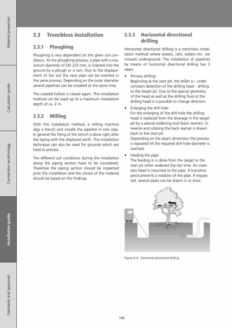
168
Mat
eria
l pro
pert
ies
Cal
cula
tion
guid
eC
onne
ctio
n te
cahn
olog
yIn
stal
lati
on
gu
ide
Stan
dard
s an
d ap
prov
als
2.3 Trenchless installation
2.3.1 Ploughing
Ploughing is very dependent on the given soil con‑ditions. At the ploughing process, a pipe with a ma‑ximum diameter of OD 225 mm, is inserted into the ground by a plough or a ram. Due to the displace‑ment of the soil the new pipe can be inserted in the same process. Depending on the outer diameter several pipelines can be installed at the same time.
The created hollow is closed again. This installation method can be used up to a maximum installation depth of ca. 2 m.
2.3.2 Milling
With this installation method, a milling machine digs a trench and installs the pipeline in one step. In general the filling of the trench is done right after the laying with the displaced earth. This installation technique can also be used for grounds which are hard to process.
The different soil conditions during the installation along the piping section have to be considered. Therefore the piping section should be inspected prior the installation and the choice of the material should be based on the findings.
2.3.3 Horizontal directional drilling
Horizontal directional drilling is a trenchless instal‑lation method where streets, rails, waters etc. are crossed underground. The installation of pipelines by means of horizontal directional drilling has 3 steps:
• Primary drilling: Beginning at the start pit, the driller is ‑ under constant detection of the drilling head ‑ drilling to the target pit. Due to the special geometry of the head as well as the drilling fluid at the drilling head it is possible to change direction.
• Enlarging the drill hole: For the enlarging of the drill hole the drilling head is replaced from the leverage in the target pit by a special widening‑tool (back reamer). In reverse and rotating the back reamer is drawn back to the start pit. Depending on the pipe’s dimension the process is repeated till the required drill hole diameter is reached.
• Feeding the pipe: The feeding in is done from the target to the start pit when widened the last time. An inser‑tion head is mounted to the pipe. A transition piece prevents a rotation of the pipe. If reques‑ted, several pipes can be drawn in at once.
Figure D.4: Horizontal directional drilling.
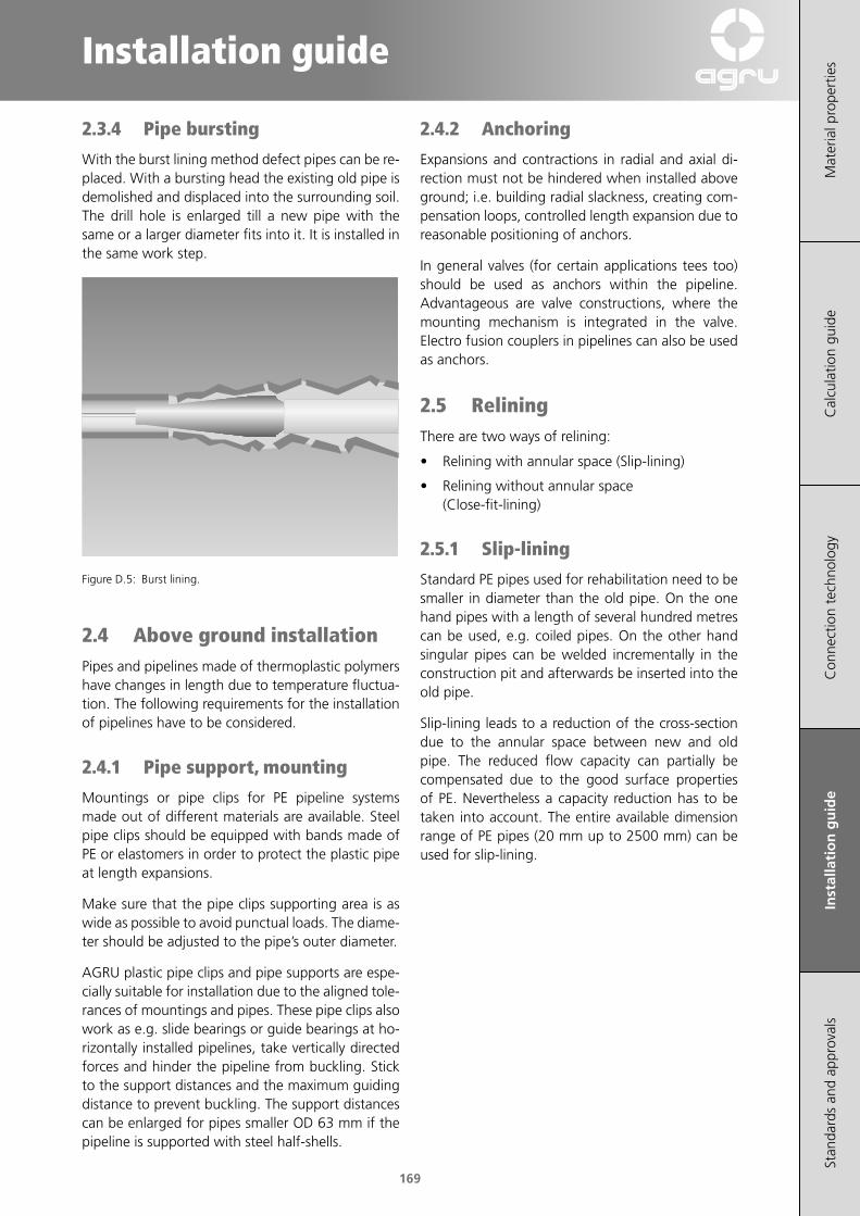
169
Installation guide
Mat
eria
l pro
pert
ies
Cal
cula
tion
guid
eC
onne
ctio
n te
chno
logy
Inst
alla
tio
n g
uid
eSt
anda
rds
and
appr
oval
s
2.3.4 Pipe bursting
With the burst lining method defect pipes can be re‑placed. With a bursting head the existing old pipe is demolished and displaced into the surrounding soil. The drill hole is enlarged till a new pipe with the same or a larger diameter fits into it. It is installed in the same work step.
Figure D.5: Burst lining.
2.4 Above ground installationPipes and pipelines made of thermoplastic polymers have changes in length due to temperature fluctua‑tion. The following requirements for the installation of pipelines have to be considered.
2.4.1 Pipe support, mounting
Mountings or pipe clips for PE pipeline systems made out of different materials are available. Steel pipe clips should be equipped with bands made of PE or elastomers in order to protect the plastic pipe at length expansions.
Make sure that the pipe clips supporting area is as wide as possible to avoid punctual loads. The diame‑ter should be adjusted to the pipe’s outer diameter.
AGRU plastic pipe clips and pipe supports are espe‑cially suitable for installation due to the aligned tole‑rances of mountings and pipes. These pipe clips also work as e.g. slide bearings or guide bearings at ho‑rizontally installed pipelines, take vertically directed forces and hinder the pipeline from buckling. Stick to the support distances and the maximum guiding distance to prevent buckling. The support distances can be enlarged for pipes smaller OD 63 mm if the pipeline is supported with steel half‑shells.
2.4.2 Anchoring
Expansions and contractions in radial and axial di‑rection must not be hindered when installed above ground; i.e. building radial slackness, creating com‑pensation loops, controlled length expansion due to reasonable positioning of anchors.
In general valves (for certain applications tees too) should be used as anchors within the pipeline. Advantageous are valve constructions, where the mounting mechanism is integrated in the valve. Electro fusion couplers in pipelines can also be used as anchors.
2.5 ReliningThere are two ways of relining:
• Relining with annular space (Slip‑lining)
• Relining without annular space (Close‑fit‑lining)
2.5.1 Slip-lining
Standard PE pipes used for rehabilitation need to be smaller in diameter than the old pipe. On the one hand pipes with a length of several hundred metres can be used, e.g. coiled pipes. On the other hand singular pipes can be welded incrementally in the construction pit and afterwards be inserted into the old pipe.
Slip‑lining leads to a reduction of the cross‑section due to the annular space between new and old pipe. The reduced flow capacity can partially be compensated due to the good surface properties of PE. Nevertheless a capacity reduction has to be taken into account. The entire available dimension range of PE pipes (20 mm up to 2500 mm) can be used for slip‑lining.
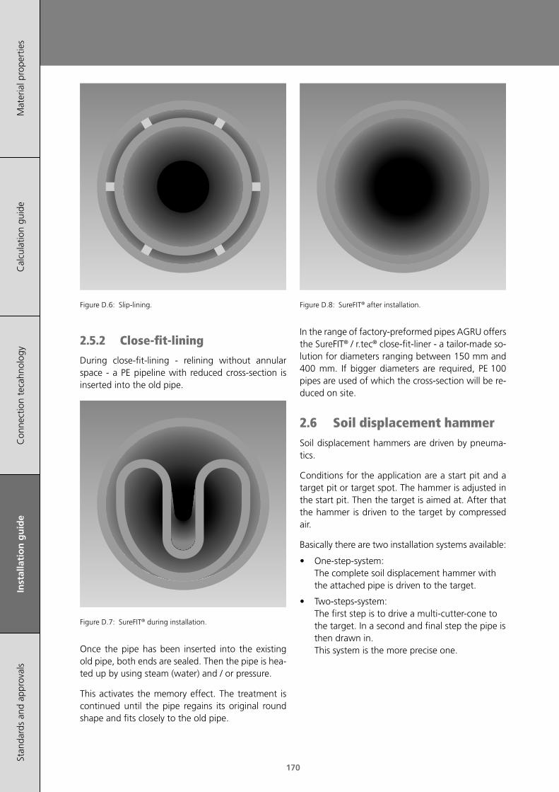
170
Mat
eria
l pro
pert
ies
Cal
cula
tion
guid
eC
onne
ctio
n te
cahn
olog
yIn
stal
lati
on
gu
ide
Stan
dard
s an
d ap
prov
als
Figure D.6: Slip‑lining.
2.5.2 Close-fit-lining
During close‑fit‑lining ‑ relining without annular space ‑ a PE pipeline with reduced cross‑section is inserted into the old pipe.
Figure D.7: SureFIT® during installation.
Once the pipe has been inserted into the existing old pipe, both ends are sealed. Then the pipe is hea‑ted up by using steam (water) and / or pressure.
This activates the memory effect. The treatment is continued until the pipe regains its original round shape and fits closely to the old pipe.
Figure D.8: SureFIT® after installation.
In the range of factory‑preformed pipes AGRU offers the SureFIT® / r.tec® close‑fit‑liner ‑ a tailor‑made so‑lution for diameters ranging between 150 mm and 400 mm. If bigger diameters are required, PE 100 pipes are used of which the cross‑section will be re‑duced on site.
2.6 Soil displacement hammerSoil displacement hammers are driven by pneuma‑tics.
Conditions for the application are a start pit and a target pit or target spot. The hammer is adjusted in the start pit. Then the target is aimed at. After that the hammer is driven to the target by compressed air.
Basically there are two installation systems available:
• One‑step‑system: The complete soil displacement hammer with the attached pipe is driven to the target.
• Two‑steps‑system: The first step is to drive a multi‑cutter‑cone to the target. In a second and final step the pipe is then drawn in. This system is the more precise one.

171
Installation guide
Mat
eria
l pro
pert
ies
Cal
cula
tion
guid
eC
onne
ctio
n te
chno
logy
Inst
alla
tio
n g
uid
eSt
anda
rds
and
appr
oval
s
In general there are two kinds of soil displacement hammers:
• uncontrolled hammers
• controlled hammers
2.6.1 Uncontrolled soil displacement hammer
Installation lengths: up to 40 m
Maximum dimension: DN 200
Maximum speed: 15 m/h
Location: target pit
Figure D.9: Uncontrolled soil displacement hammer.
2.6.2 Controlled soil displacement hammer
Installation lengths: up to 70 m
Maximum dimension: DN 65
Maximum speed: 10 m/h
Minimum radius R: 27 m
Location: target pit or target spot
R
Figure D.10: Controlled soil displacement hammer.
Besides course corrections, the controlled soil dis‑placement hammer holds another advantage. It can record the data of its course (pitches, side motions and depths information). These data can be trans‑ferred to a computer and be stored as a path‑dia‑gram.
3 Product-specific characteristics for relining
3.1 Specifics of PE 100Slip‑lining: suitable
Close‑fit‑lining: suitable (above DN 400 mm); after a technical consultation with the technical enginee‑ring department ([email protected])
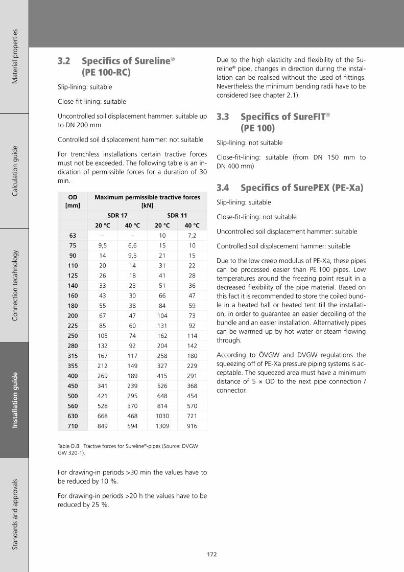
172
Mat
eria
l pro
pert
ies
Cal
cula
tion
guid
eC
onne
ctio
n te
cahn
olog
yIn
stal
lati
on
gu
ide
Stan
dard
s an
d ap
prov
als
Due to the high elasticity and flexibility of the Su‑reline® pipe, changes in direction during the instal‑lation can be realised without the used of fittings. Nevertheless the minimum bending radii have to be considered (see chapter 2.1).
3.3 Specifics of SureFIT® (PE 100)
Slip‑lining: not suitable
Close‑fit‑lining: suitable (from DN 150 mm to DN 400 mm)
3.4 Specifics of SurePEX (PE-Xa)Slip‑lining: suitable
Close‑fit‑lining: not suitable
Uncontrolled soil displacement hammer: suitable
Controlled soil displacement hammer: suitable
Due to the low creep modulus of PE‑Xa, these pipes can be processed easier than PE 100 pipes. Low temperatures around the freezing point result in a decreased flexibility of the pipe material. Based on this fact it is recommended to store the coiled bund‑le in a heated hall or heated tent till the installati‑on, in order to guarantee an easier decoiling of the bundle and an easier installation. Alternatively pipes can be warmed up by hot water or steam flowing through.
According to ÖVGW and DVGW regulations the squeezing off of PE‑Xa pressure piping systems is ac‑ceptable. The squeezed area must have a minimum distance of 5 × OD to the next pipe connection / connector.
3.2 Specifics of Sureline® (PE 100-RC)
Slip‑lining: suitable
Close‑fit‑lining: suitable
Uncontrolled soil displacement hammer: suitable up to DN 200 mm
Controlled soil displacement hammer: not suitable
For trenchless installations certain tractive forces must not be exceeded. The following table is an in‑dication of permissible forces for a duration of 30 min.
OD [mm]
Maximum permissible tractive forces [kN]
SDR 17 SDR 11
20 °C 40 °C 20 °C 40 °C
63 ‑ ‑ 10 7,2
75 9,5 6,6 15 10
90 14 9,5 21 15
110 20 14 31 22
125 26 18 41 28
140 33 23 51 36
160 43 30 66 47
180 55 38 84 59
200 67 47 104 73
225 85 60 131 92
250 105 74 162 114
280 132 92 204 142
315 167 117 258 180
355 212 149 327 229
400 269 189 415 291
450 341 239 526 368
500 421 295 648 454
560 528 370 814 570
630 668 468 1030 721
710 849 594 1309 916
Table D.8: Tractive forces for Sureline®‑pipes (Source: DVGW GW 320‑1).
For drawing‑in periods >30 min the values have to be reduced by 10 %.
For drawing‑in periods >20 h the values have to be reduced by 25 %.

173
Installation guide
Mat
eria
l pro
pert
ies
Cal
cula
tion
guid
eC
onne
ctio
n te
chno
logy
Inst
alla
tio
n g
uid
eSt
anda
rds
and
appr
oval
s
MachiningCutting
t Clearance angle αRake angle γPitch tCutting speed ν
[°][°][mm][m/min]
20 ‑ 302 ‑ 53 ‑ 8500
Band saws are appropriate for the cutting of pipes, blocks, thick sheets and round bars.
Cutting
α
γ
Clearance angle αRake angle γPitch tCutting speed ν
[°][°][mm][m/min]
20 ‑ 306 ‑ 103 ‑ 82000
Circular saws can be used for the cutting of pipes, blocks and sheets. Carbide tipped saws have a con‑siderably longer working life.
Turning
a
λ
γ
α
Clearance angle αRake angle γTool angle λCutting speed νFeed fCutting depth a
[°][°][°][m/min][mm/min‑1][mm]
6 ‑ 100 ‑ 545 ‑ 60250 ‑ 5000.1 ‑ 0.5> 0.5
The peak radius (r) should be at least 0.5 mm. High surface quality is obtained by means of a cutting tool with a wide finishing blade. Cut‑off: Sharpen turning tool like a knife.
Milling
α
γ
Clearance angle αRake angle γCutting speed νFeed f
[°][°][m/min][mm/min‑1]
10 ‑ 205 ‑ 15250 ‑ 5000.5
High surface quality is obtained by means of a milling machine with fewer blades ‑ this increases cutting capacity.
Drilling
ϕ
α
γ
Clearance angle αRake angle γCentre angle φCutting speed νFeed fSpiral angle γx
[°][°][°][m/min][mm/min‑1][°]
5 ‑ 1510 ‑ 2060 ‑ 9050 ‑ 1500.1 ‑ 0.312 ‑ 16
For holes with diameters of 40 mm ‑ 150 mm, hollow drills should be used; for holes <40 mm diameter, use a normal high‑speed‑steel drill.
Table D.9: Parameter guidelines for machining processes.
The cutting speed, the conveying and the cutting geometry should be designed in a way that any sub‑sequent heat can mainly be removed through the shavings (too much pre‑heating can lead to melting and/or discolouration of the processed surface).
All usual metal and wood processing machines may be applied.
Caution: the usage of silicone grease or other lubri‑cants, which can negatively affect the welding result is not permitted.

174
Mat
eria
l pro
pert
ies
Cal
cula
tion
guid
eC
onne
ctio
n te
cahn
olog
yIn
stal
lati
on
gu
ide
Stan
dard
s an
d ap
prov
als

175
Mat
eria
l pro
pert
ies
Cal
cula
tion
guid
eIn
stal
latio
n gu
ide
Con
nect
ion
tech
nolo
gySt
and
ard
s an
d a
pp
rova
ls
Standards and Approvals
175
1 Standards 177
2 Approvals / External quality control 177

176
Mat
eria
l pro
pert
ies
Cal
cula
tion
guid
eIn
stal
latio
n gu
ide
Con
nect
ion
tech
nolo
gySt
and
ard
s an
d a
pp
rova
ls
177
Mat
eria
l pro
pert
ies
Cal
cula
tion
guid
eIn
stal
latio
n gu
ide
Con
nect
ion
tech
nolo
gySt
and
ard
s an
d a
pp
rova
ls
Standards and Approvals
1 StandardsAGRU pipes and fittings are manufactured out of standardised moulding materials and produced ac‑cording to relevant international standards.
A summary of the most important standards for PE is listed below.
• ÖNORM B 5014‑1: Sensory and chemical requi‑rements and testing of materials in contact with drinking water ‑ Part 1: Organic materials.
• DIN 8074: Polyethylene (PE) ‑ Pipes PE 63, PE 80, PE 100, HDPE ‑ Dimensions.
• DIN 8075: Polyethylene (PE) pipes ‑ PE 63, PE 80, PE 100, HDPE ‑ General quality require‑ments, testing.
• DIN 16963 (part 1 ‑ part 15): Pipe Joints and Elements for High Density Polyethylene (HDPE) Pressure Pipelines, Types 1 and 2.
• EN 1555 (part 1 ‑ part 7): Plastics piping sys‑tems for the supply of gaseous fuels ‑ Polyethy‑lene (PE).
• EN 12201 (part 1 ‑ part 7): Plastics piping sys‑tems for water supply ‑ Polyethylene (PE).
• ISO 1872‑1: Plastics ‑ Polyethylene (PE) moul‑ding and extrusion materials.
• ISO 4065: Thermoplastics pipes ‑ Universal wall thickness table.
• ISO 4427: Plastics piping systems ‑ Polyethylene (PE) pipes and fittings for water supply.
• ISO 4437: Buried polyethylene (PE) pipes for the supply of gaseous fuels ‑ Metric series ‑ Specifi‑cations.
• ÖVGW QS‑G 392 (Teil 1‑4):Polyethylene pipings systems PE 80, PE 100 and PE 100‑RC for the supply of gaseous fuels
• ÖVGW PW 406 (Part1‑3): Polyethylene (PE 40, PE 80 und PE 100) pipesystems for the supply of drinking water ‑ Part 1 ‑ pipes
• GRIS GV 19: Spezielle Gütevorschrift für Kanal‑rohre und Formstücke aus Polyethylen (PE) für den Siedlungswasserbau
• GRIS GV 20: Spezielle Gütevorschrift für Kanal‑Druckrohre und Formstücke aus Polyethylen PE 100‑RC für nicht konventionelle Verlegetechni‑ken im Siedlungswasserbau
• PAS 1075: Pipes made from Polyethylene for alternative installation techniques
• DVGW W 400/1: Technische Regel Wasserver‑teilungsanlagen (TRWV) ‑ Teil 1: Planung
• ASTM D2513: Standard Specification for Po‑lyethylene (PE) Gas Pressure Pipe, Tubing, and Fittings
• ASTM D3261: Standard Specification for Butt Heat Fusion Polyethylene (PE) Plastic Fittings for Polyethylene (PE) Plastic Pipe and Tubing
• ASTM F1055: Standard Specification for Elec‑trofusion Type Polyethylene Fittings for Outside Diameter Controlled Polyethylene and Cross‑linked Polyethylene (PEX) Pipe and Tubing
2 Approvals / External quality control
Additionally to the internal controls, regular tests on products and internal procedures are performed by independently accredited test institutes.
External control is one element of product approvals in several application ranges and countries, where the modalities of the external control are regulated in registration and approval certificates.
Currently the following institutes are commissioned for production control:
• IIP Milano (Italy)
• MPA Darmstadt (Germany)
• TGM Vienna (Austria)
• TÜV Süd (Southern Germany)
• Certigaz

178
Mat
eria
l pro
pert
ies
Cal
cula
tion
guid
eIn
stal
latio
n gu
ide
Con
nect
ion
tech
nolo
gySt
and
ard
s an
d a
pp
rova
ls
The high quality standard of our products is docu‑mented by a series of approvals and certification for gas and water supply in following countries:
Country Approval Natural gas Potable water Sewage
Algeria Sonelgaz ×
Australia Watermark ×
AustriaÖVGW × ×
GRIS ×
BelgiumBELGAQUA ×
Electrabel ×
EuropeEN 12201 × ×
EN 1555 × ×
France Gaz de France ×
GermanyDVGW × ×
Dibt × ×
Great Britain & Northern Ireland
WRAS ×
Italy IIP ‑ UNI × ×
New Zealand Watermark ×
Poland Install × ×
RussiaDIN Gost TÜV × ×
GasCert ×
Spain GAS NATURAL ×
Switzerland SVGW × ×
Table E.1: Overview approvals.
FM approved 175 psi and 200 psi PE pipes and fit‑tings (OD 63 ‑ 500 mm) according to FM class 1613 “Plastic pipes and fittings for underground fire pro‑tection service“.
DNV approval for the use of pipes/fittings made of PE100 / PE100‑RC in systems for water and sea water.

www.agru.at
AGRU Kunststofftechnik GmbHIng.-Pesendorfer-Straße 314540 Bad Hall, Austria
T. +43 7258 7900F. +43 7258 790 - [email protected]
AG
RU
LIN
E
0117
AGRULINE
PIPING SYSTEMS FOR NATURAL GAS, WATER & SEWAGE
ROHRSYSTEME FÜR GAS, WASSER & ABWASSER
ENDE
Ihr Fachhändler / Your distributor:
Subject to errors of typesetting, misprints and modifications. Illustrations are generic and for reference only.
Satzfehler, Druckfehler und Änderungen vorbehalten.Abbildungen sind teilweise Symbolfotos.
Piping SystemsAGRULINE | INDUSTRIAL | PURAD | AGRUSAN/AGRUAIR
Semi-Finished ProductsSHEETS | ROUND BARS | RODS
Concrete ProtectionSURE GRIP | ULTRA GRIP | HYDROCLICK
Lining SystemsGEOMEMBRANES | AUSTROPLAN - ROOF LINER AGRUFLEX - TUNNEL LINER