
AERODROMES - ULisboa · AERODROMES ANNEX 14 ... The issue of amendments is announced regularly in...
62
INTERNATIONAL STANDARDS AND RECOMMENDED PRACTICES AERODROMES ANNEX 14 TO THE CONVENTION ON INTERNATIONAL CIVIL AVIATION VOLUME II HELIPORTS SECOND EDITION — JULY 1995 This edition incorporates all amendments to Annex 14, Volume II, adopted by the Council prior to 14 March 1995 and supersedes on 9 November 1995 all previous editions of Annex 14, Volume II. For information regarding the applicability of the Standards and Recommended Practices, see Foreword and the relevant clauses in each Chapter INTERNATIONAL CIVIL AVIATION ORGANIZATION
Transcript of AERODROMES - ULisboa · AERODROMES ANNEX 14 ... The issue of amendments is announced regularly in...

INTERNATIONAL STANDARDSAND RECOMMENDED PRACTICES
AERODROMES
ANNEX 14
TO THE CONVENTION ON INTERNATIONAL CIVIL AVIATION
VOLUME IIHELIPORTS
SECOND EDITION — JULY 1995
This edition incorporates all amendments to Annex 14, Volume II, adoptedby the Council prior to 14 March 1995 and supersedes on
9 November 1995 all previous editions of Annex 14, Volume II.
For information regarding the applicability of the Standards andRecommended Practices, see Foreword and the relevant clauses in
each Chapter
INTERNATIONAL CIVIL AVIATION ORGANIZATION

AMENDMENTS
The issue of amendments is announced regularly in the ICAO Journal and in themonthly Supplement to the Catalogue of ICAO Publications and Audio-visualTraining Aids, which holders of this publication should consult. The space belowis provided to keep a record of such amendments.
RECORD OF AMENDMENTS AND CORRIGENDA
AMENDMENTS CORRIGENDA
No.Date
applicableDate
enteredEntered
by No.Date
of issueDate
enteredEntered
by
1 Incorporated in this edition 20/10/95
2 6/11/97
9/11/95 (ii)

0
1010101
111
122
122333
30
300
300
1
2
224555566
383889925
6
67
TABLE OF CONTENTS
Page Page
Abbreviations and symbols; manuals. . . . . . . . . . . . . . . (v)
FOREWORD . . . . . . . . . . . . . . . . . . . . . . . . . . . . . . . . . (vii)
CHAPTER 1. General . . . . . . . . . . . . . . . . . . . . . . . . . 1
1.1 Definitions . . . . . . . . . . . . . . . . . . . . . . . . . . . . . 11.2 Applicability . . . . . . . . . . . . . . . . . . . . . . . . . . . . 2
CHAPTER 2. Heliport data . . . . . . . . . . . . . . . . . . . . . 3
2.1 Aeronautical data . . . . . . . . . . . . . . . . . . . . . . . . 32.2 Heliport reference point . . . . . . . . . . . . . . . . . . . 32.3 Heliport elevation. . . . . . . . . . . . . . . . . . . . . . . . 42.4 Heliport dimensions and related information . . 42.5 Declared distances . . . . . . . . . . . . . . . . . . . . . . . 42.6 Co-ordination between aeronautical
information services and heliport authorities . . 4
CHAPTER 3. Physical characteristics . . . . . . . . . . . . 5
3.1 Surface-level heliports . . . . . . . . . . . . . . . . . . . . 5— Final approach and take-off areas . . . . . . . . 5— Helicopter clearways. . . . . . . . . . . . . . . . . . . 5— Touchdown and lift-off areas . . . . . . . . . . . . 5— Safety areas . . . . . . . . . . . . . . . . . . . . . . . . . . 6— Helicopter ground taxiways . . . . . . . . . . . . . 6— Air taxiways . . . . . . . . . . . . . . . . . . . . . . . . . 7— Air transit route. . . . . . . . . . . . . . . . . . . . . . . 7— Aprons . . . . . . . . . . . . . . . . . . . . . . . . . . . . . . 7— Location of a final approach and take-off
area in relation to a runway or taxiway . . . . 8
3.2 Elevated heliports. . . . . . . . . . . . . . . . . . . . . . . . 8— Final approach and take-off area and
touchdown and lift-off area . . . . . . . . . . . . . 8— Safety area. . . . . . . . . . . . . . . . . . . . . . . . . . . 8
3.3 Helidecks . . . . . . . . . . . . . . . . . . . . . . . . . . . . . . 9— Final approach and take-off area and
touchdown and lift-off area . . . . . . . . . . . . . 9
3.4 Shipboard heliports . . . . . . . . . . . . . . . . . . . . . . 9— Final approach and take-off area and
touchdown and lift-off area . . . . . . . . . . . . . 9
CHAPTER 4. Obstacle restriction and removal . . . . . 1
4.1 Obstacle limitation surfaces and sectors . . . . . . — Approach surface . . . . . . . . . . . . . . . . . . . . . . — Transitional surface . . . . . . . . . . . . . . . . . . . . — Inner horizontal surface . . . . . . . . . . . . . . . . . 1— Conical surface . . . . . . . . . . . . . . . . . . . . . . . — Take-off climb surface. . . . . . . . . . . . . . . . . . 1— Obstacle-free sector/surface — helidecks . . . — Limited obstacle surface — helidecks . . . . . 1
4.2 Obstacle limitation requirements . . . . . . . . . . . . — Surface level heliports . . . . . . . . . . . . . . . . . . 1— Elevated heliports . . . . . . . . . . . . . . . . . . . . . 1— Helidecks . . . . . . . . . . . . . . . . . . . . . . . . . . . . 1— Shipboard heliports . . . . . . . . . . . . . . . . . . . . 1
CHAPTER 5. Visual aids. . . . . . . . . . . . . . . . . . . . . . .
5.1 Indicators. . . . . . . . . . . . . . . . . . . . . . . . . . . . . . . 5.1.1 Wind direction indicators. . . . . . . . . . . . 3
5.2 Markings and markers . . . . . . . . . . . . . . . . . . . . 5.2.1 Winching area marking . . . . . . . . . . . . . 35.2.2 Heliport identification marking . . . . . . . 305.2.3 Maximum allowable mass marking. . . . 35.2.4 Final approach and take-off area
marking or marker . . . . . . . . . . . . . . . . . 35.2.5 Final approach and take-off area
designation marking . . . . . . . . . . . . . . . . 35.2.6 Aiming point marking . . . . . . . . . . . . . . 35.2.7 Touchdown and lift-off area marking . . 35.2.8 Touchdown marking . . . . . . . . . . . . . . . 35.2.9 Heliport name marking . . . . . . . . . . . . . 35.2.10 Helideck obstacle-free sector marking . 35.2.11 Marking for taxiways. . . . . . . . . . . . . . . 35.2.12 Air taxiway markers. . . . . . . . . . . . . . . . 35.2.13 Air transit route markers . . . . . . . . . . . . 3
5.3 Lights. . . . . . . . . . . . . . . . . . . . . . . . . . . . . . . . . . 5.3.1 General . . . . . . . . . . . . . . . . . . . . . . . . . . 5.3.2 Heliport beacon . . . . . . . . . . . . . . . . . . . 35.3.3 Approach lighting system . . . . . . . . . . . 35.3.4 Visual alignment guidance system . . . . 35.3.5 Visual approach slope indicator. . . . . . . 45.3.6 Final approach and take-off area lights. 45.3.7 Aiming point lights . . . . . . . . . . . . . . . . 45.3.8 Touchdown and lift-off area
lighting system . . . . . . . . . . . . . . . . . . . . 45.3.9 Winching area floodlighting . . . . . . . . . 4
ANNEX 14 — VOLUME II (iii) 9/11/956/11/97No. 2

Annex 14 — Aerodromes Volume II
Page Page
995050
51
5.3.10 Taxiway lights . . . . . . . . . . . . . . . . . . . . 475.3.11 Visual aids for denoting obstacles . . . . 475.3.12 Floodlighting of obstacles . . . . . . . . . . . 47
CHAPTER 6. Heliport services. . . . . . . . . . . . . . . . . . 49
6.1 Rescue and fire fighting. . . . . . . . . . . . . . . . . . . 49— General . . . . . . . . . . . . . . . . . . . . . . . . . . . . . 49
— Level of protection to be provided . . . . . . . . 4— Extinguishing agents . . . . . . . . . . . . . . . . . . . 4— Rescue equipment . . . . . . . . . . . . . . . . . . . . . — Response time . . . . . . . . . . . . . . . . . . . . . . . .
APPENDIX 1. Aeronautical data quality requirements . . . . . . . . . . . . . . . . . . . . . . . . . . . .
9/11/95 (iv)6/11/97No. 2

ANNEX 14 — VOLUME II (v) 9/11/95
ABBREVIATIONS AND SYMBOLS(used in Annex 14, Volume II)
Abbreviations Abbreviations
cd Candelacm CentimeterD Helicopter largest over-all dimensionFATO Final approach and take-off areaft FootHAPI Helicopter approach path indicatorHz HertzIMC Instrument meteorological conditionskg Kilogramkm/h Kilometre per hourkt KnotL LitreLDAH Landing distance availableL/min Litre per minutem Metre
RD Diameter of the largest rotorRTODAH Rejected take-off distance availables SecondTLOF Touchdown and lift-off areaTODAH Take-off distance availableVMC Visual meteorological conditions
Symbols
° Degree= Equals% Percentage± Plus or minus
MANUALS(related to the specifications of this Annex)
Aerodrome Design Manual (Doc 9157)Part 1 — RunwaysPart 2 — Taxiways, Aprons and Holding BaysPart 3 — PavementsPart 4 — Visual AidsPart 5 — Electrical Systems
Airport Planning Manual (Doc 9184)Part 1 — Master PlanningPart 2 — Land Use and Environmental ControlPart 3 — Guidelines for Consultant/Construction Services
Airport Services Manual (Doc 9137)Part 1 — Rescue and Fire FightingPart 2 — Pavement Surface ConditionsPart 3 — Bird Control and Reduction
Part 4 — Fog Dispersal (withdrawn)Part 5 — Removal of Disabled AircraftPart 6 — Control of ObstaclesPart 7 — Airport Emergency PlanningPart 8 — Airport Operational ServicesPart 9 — Airport Maintenance Practices
Heliport Manual (Doc 9261)
Stolport Manual (Doc 9150)
Manual on the ICAO Bird Strike Information System (IBIS)(Doc 9332)
Manual of Surface Movement Guidance and Control Systems (SMGCS) (Doc 9476)

f
ro-ce
d ince
otx;
n.
e,ofor
hhf
l,m
he-gth
lys
he
dlf-
FOREWORD
Historical background
Standards and Recommended Practices for aerodromes werefirst adopted by the Council on 29 May 1951 pursuant to theprovisions of Article 37 of the Convention on InternationalCivil Aviation (Chicago 1944) and designated as Annex 14 tothe Convention. The document containing these Standards andRecommended Practices is now designated as Annex 14,Volume I to the Convention. In general, Volume I addressesplanning, design and operations of aerodromes but is notspecifically applicable to heliports.
Therefore, Volume II is being introduced as a means ofincluding provisions for heliports. Proposals forcomprehensive Standards and Recommended Practicescovering all aspects of heliport planning, design andoperations have been developed with the assistance of theANC Visual Aids Panel and the ANC Helicopter OperationsPanel.
Table A shows the origin of the provisions in this volume,together with a list of the principal subjects involved and thedates on which the Annex was adopted by the Council, whenit became effective and when it became applicable.
Action by Contracting States
Notification of differences. The attention of Contracting Statesis drawn to the obligation imposed by Article 38 of theConvention by which Contracting States are required to notifythe Organization of any differences between their nationalregulations and practices and the International Standardscontained in this Annex and any amendments thereto.Contracting States are invited to extend such notification toany differences from Recommended Practices contained inthis Annex and any amendments thereto, when the notificationof such differences is important for the safety of airnavigation. Further, Contracting States are invited to keep theOrganization currently informed of any differences which maysubsequently occur, or of the withdrawal of any differencespreviously notified. A specified request for notification ofdifferences will be sent to Contracting States immediately afterthe adoption of each amendment to this Annex.
The attention of States is also drawn to the provisions ofAnnex 15 related to the publication of differences betweentheir national regulations and practices and the related ICAOStandards and Recommended Practices through the Aero-
nautical Information Service, in addition to the obligation oStates under Article 38 of the Convention.
Promulgation of information. The establishment andwithdrawal of and changes to facilities, services and pcedures affecting aircraft operations provided in accordanwith the Standards and Recommended Practices specifiethis Annex should be notified and take effect in accordanwith the provisions of Annex 15.
Status of Annex components
An Annex is made up of the following component parts, nall of which, however, are necessarily found in every Annethey have the status indicated:
1. — Material comprising the Annex proper:
a) Standards and Recommended Practices adopted bythe Council under the provisions of the ConventioThey are defined as follows:
Standard: Any specification for physicalcharacteristics, configuration, matériel, performancpersonnel or procedure, the uniform application which is recognized as necessary for the safety regularity of international air navigation and to whicContracting States will conform in accordance witthe Convention; in the event of impossibility ocompliance, notification to the Council iscompulsory under Article 38.
Recommended Practice: Any specification forphysical characteristics, configuration, matérieperformance, personnel or procedure, the uniforapplication of which is recognized as desirable in tinterest of safety, regularity or efficiency of international air navigation, and to which ContractinStates will endeavour to conform in accordance withe Convention.
b) Appendices comprising material grouped separatefor convenience but forming part of the Standardand Recommended Practices adopted by tCouncil.
c) Definitions of terms used in the Standards anRecommended Practices which are not se
ANNEX 14 — VOLUME II (vii) 9/11/95

Annex 14 — Aerodromes Volume II
ish, is ofinghhe
ate
by
erbtive
inasilvenits. thatay,is
isof
explanatory in that they do not have accepteddictionary meanings. A definition does not haveindependent status but is an essential part of eachStandard and Recommended Practice in which theterm is used, since a change in the meaning of theterm would affect the specifications.
d) Tables and Figures which add to or illustrate aStandard or Recommended Practice and which arereferred to therein, form part of the associatedStandard or Recommended Practice and have thesame status.
2.— Material approved by the Council for publication inassociation with the Standards and Recommended Practices:
a) Forewords comprising historical and explanatorymaterial based on the action of the Council andincluding an explanation of the obligations of Stateswith regard to the application of the Standards andRecommended Practices ensuing from theConvention and the Resolution of Adoption.
b) Introductions comprising explanatory materialintroduced at the beginning of parts, chapters orsections of the Annex to assist in the understandingof the application of the text.
c) Notes included in the text, where appropriate, to givefactual information or references bearing on theStandards or Recommended Practices in question,but not constituting part of the Standards orRecommended Practices.
d) Attachments comprising material supplementary tothe Standards and Recommended Practices, orincluded as a guide to their application.
Selection of language
This Annex has been adopted in four languages — EnglFrench, Russian and Spanish. Each Contracting Staterequested to select one of those texts for the purposenational implementation and for other effects provided for the Convention, either through direct use or throutranslation into its own national language, and to notify tOrganization accordingly.
Editorial practices
The following practice has been adhered to in order to indicat a glance the status of each statement: Standards have beenprinted in light face roman; Recommended Practices havebeen printed in light face italics, the status being indicatedthe prefix Recommendation; Notes have been printed in lightface italics, the status being indicated by the prefix Note.
The following editorial practice has been followed in thwriting of specifications: for Standards the operative ve“shall” is used, and for Recommended Practices the operaverb “should’’ is used.
The units of measurement used in this document areaccordance with the International System of Units (SI) specified in Annex 5 to the Convention on International CivAviation. Where Annex 5 permits the use of non-SI alternatiunits these are shown in parentheses following the basic uWhere two sets of units are quoted it must not be assumedthe pairs of values are equal and interchangeable. It mhowever, be inferred that an equivalent level of safety achieved when either set of units is used exclusively.
Any reference to a portion of this document, which identified by a number and/or title, includes all subdivisions that portion.
9/11/95 (viii)

Foreword Annex 14 — Aerodromes
(ix) 9/11/95
Table A. Amendments to Annex 14, Volume II
Amendment Source(s) Subject(s)
AdoptedEffective
Applicable
1st Edition Fourth Meeting of the ANC Helicopter Operations Panel; Eleventh meeting of the ANC Visual Aids Panel and Secretariat
Physical characteristics; obstacle limitation surfaces; visual aids for visual meteorological conditions; rescue and fire fighting services.
9 March 199030 July 190015 November 1990
1 (2nd Edition)
Twelfth Meeting of the ANC Visual Aids Panel and Secretariat
Standard geodetic reference system (WGS-84); frangibility; visual aids for helicopter non-precision approaches; and visual alignment guidance system.
13 March 199524 July 19959 November 1995
2 Air NavigationCommission
Aeronautical data bases and vertical component of the World Geodetic System — 1984 (WGS-84).
21 March 199721 July 19976 November 1997
6/11/97No. 2
tarms
ofd
ed1
reatoht.
n
ter
toff
sedrea
oem
evel
al.)at
INTERNATIONAL STANDARDSAND RECOMMENDED PRACTICES
CHAPTER 1. GENERAL
Introductory Note.— Volume II of this Annex containsStandards and Recommended Practices (specifications) thatprescribe the physical characteristics and obstacle limitationsurfaces to be provided for at heliports, and certain facilitiesand technical services normally provided at a heliport. It isnot intended that these specifications limit or regulate theoperation of an aircraft.
The specifications in this volume modify or complementthose in Volume I which, where appropriate, are alsoapplicable to heliports. In other words, where a particularissue is a subject of a specification in this volume thatspecification will supersede any other specification on thatparticular issue in Volume I. Throughout this volume the term“heliport” is used; however, it is intended that thesespecifications also apply to areas for the exclusive use ofhelicopters at an aerodrome primarily meant for the use ofaeroplanes.
It is to be noted that provisions for helicopter flightoperations are contained in Annex 6, Part III.
1.1 Definitions
When the following terms are used in this volume they havethe meanings given below. Annex 14, Volume I containsdefinitions for those terms which are used in both volumes.
Accuracy. A degree of conformance between the estimated ormeasured value and the true value.
Note.— For measured positional data the accuracy isnormally expressed in terms of a distance from a statedposition within which there is a defined confidence of the trueposition falling.
Air taxiway. A defined path on the surface established for theair taxiing of helicopters.
Air transit route. A defined path on the surface established forthe air transitting of helicopters.
Cyclic redundancy check (CRC). A mathematical algorithmapplied to the digital expression of data that provides alevel of assurance against loss or alteration of data.
Data quality. A degree or level of confidence that the daprovided meets the requirements of the data user in teof accuracy, resolution and integrity.
Declared distances — heliports.
a) Take-off distance available (TODAH). The length of thefinal approach and take-off area plus the length helicopter clearway (if provided) declared available ansuitable for helicopters to complete the take-off.
b) Rejected take-off distance available (RTODAH). Thelength of the final approach and take-off area declaravailable and suitable for performance class helicopters to complete a rejected take-off.
c) Landing distance available (LDAH). The length of thefinal approach and take-off area plus any additional adeclared available and suitable for helicopters complete the landing manoeuvre from a defined heig
Elevated heliport. A heliport located on a raised structure oland.
Ellipsoid height (Geodetic height). The height related to thereference ellipsoid, measured along the ellipsoidal ounormal through the point in question.
Final approach and take-off area (FATO). A defined areaover which the final phase of the approach manoeuvrehover or landing is completed and from which the take-omanoeuvre is commenced. Where the FATO is to be uby performance Class 1 helicopters, the defined aincludes the rejected take-off area available.
Geodetic datum. A minimum set of parameters required tdefine location and orientation of the local reference systwith respect to the global reference system/frame.
Geoid. The equipotential surface in the gravity field of thEarth which coincides with the undisturbed mean sea le(MSL) extended continuously through the continents.
Note.— The geoid is irregular in shape because of locgravitational disturbances (wind tides, salinity, current, etcand the direction of gravity is perpendicular to the geoid every point.
ANNEX 14 — VOLUME II 1 9/11/956/11/97No. 2

Annex 14 — Aerodromes Volume II
riskhe
othe
intheheionits
orith
ll in,
as
e,o
Geoid undulation. The distance of the geoid above (positive)or below (negative) the mathematical reference ellipsoid.
Note.— In respect to the World Geodetic System — 1984(WGS-84) defined ellipsoid, the difference between the WGS-84 ellipsoidal height and orthometric height representsWGS-84 geoid undulation.
Helicopter ground taxiway. A ground taxiway for use byhelicopters only.
Helicopter clearway. A defined area on the ground or waterunder the control of the appropriate authority, selected and/or prepared as a suitable area over which a performanceclass 1 helicopter may accelerate and achieve a specificheight.
Helicopter stand. An aircraft stand which provides for parkinga helicopter and, where air taxiing operations arecontemplated, the helicopter touchdown and lift-off.
Helideck. A heliport located on a floating or fixed off-shorestructure.
Heliport. An aerodrome or a defined area on a structureintended to be used wholly or in part for the arrival,departure and surface movement of helicopters.
Integrity (aeronautical data). A degree of assurance that anaeronautical data and its value has not been lost nor alteredsince the data origination or authorized amendment.
Orthometric height. Height of a point related to the geoid,generally presented as an MSL elevation.
Safety area. A defined area on a heliport surrounding theFATO which is free of obstacles, other than those required
for air navigation purposes, and intended to reduce the of damage to helicopters accidentally diverging from tFATO.
Station declination. An alignment variation between the zerdegree radial of a VOR and true north, determined at time the VOR station is calibrated.
Surface level heliport. A heliport located on the ground or onthe water.
Touchdown and lift-off area (TLOF). A load bearing area onwhich a helicopter may touch down or lift off.
1.2 Applicability
1.2.1 The interpretation of some of the specifications the Annex expressly requires the exercising of discretion, taking of a decision or the performance of a function by tappropriate authority. In other specifications, the expressappropriate authority does not actually appear although inclusion is implied. In both cases, the responsibility fwhatever determination or action is necessary shall rest wthe State having jurisdiction over the heliport.
1.2.2 The specifications in Annex 14, Volume II shaapply to all heliports intended to be used by helicoptersinternational civil aviation. The specifications of Annex 14Volume I shall apply, where appropriate, to these heliportswell.
1.2.3 Wherever a colour is referred to in this volumthe specifications for that colour given in Appendix 1 tAnnex 14, Volume I shall apply.
9/11/95 26/11/97No. 2

ityd
cyAild
ndticalticm,en
ansthe
ethehbles
seats,ornedity.
chith
S-15,
r a
e,oth
arall
CHAPTER 2. HELIPORT DATA
2.1 Aeronautical data
2.1.1 Determination and reporting of heliport relatedaeronautical data shall be in accordance with the accuracy andintegrity requirements set forth in Tables 1 to 5 contained inAppendix 1 while taking into account the established qualitysystem procedures. Accuracy requirements for aeronauticaldata are based upon a 95 per cent confidence level and in thatrespect, three types of positional data shall be identified:surveyed points (e.g. FATO threshold), calculated points(mathematical calculations from the known surveyed points ofpoints in space, fixes) and declared points (e.g. flightinformation region boundary points).
Note. — Specifications governing the quality system aregiven in Annex 15, Chapter 3.
2.1.2 Contracting States shall ensure that integrity ofaeronautical data is maintained throughout the data processfrom survey/origin to the next intended user. Aeronautical dataintegrity requirements shall be based upon the potential riskresulting from the corruption of data and upon the use towhich the data item is put. Consequently, the followingclassification and data integrity level shall apply:
a) critical data, integrity level 1 × 10⁻⁸: there is a highprobability when using corrupted critical data that thecontinued safe flight and landing of an aircraft would beseverely at risk with the potential for catastrophe;
b) essential data, integrity level 1 × 10⁻⁵: there is a lowprobability when using corrupted essential data that thecontinued safe flight and landing of an aircraft would beseverely at risk with the potential for catastrophe; and
c) routine data, integrity level 1 × 10⁻³: there is a very lowprobability when using corrupted routine data that thecontinued safe flight and landing of an aircraft would beseverely at risk with the potential for catastrophe.
2.1.3 Protection of electronic aeronautical data whilestored or in transit shall be totally monitored by the cyclicredundancy check (CRC). To achieve protection of theintegrity level of critical and essential aeronautical data asclassified in 2.1.2 above, a 32 or 24 bit CRC algorithm shallapply respectively.
2.1.4 Recommendation. — To achieve protection of theintegrity level of routine aeronautical data as classified in 2.1.2above, a 16 bit CRC algorithm should apply.
Note.— Guidance material on the aeronautical data qualrequirements (accuracy, resolution, integrity, protection antraceability) is contained in the World Geodetic System —1984 (WGS-84) Manual (Doc 9674). Supporting material inrespect of the provisions of Appendix 1 related to accuraand integrity of aeronautical data, is contained in RTCDocument DO-201A and European Organization for CivAviation Equipment (EUROCAE) Document ED-77, entitle“Industry Requirements for Aeronautical Information”.
2.1.5 Geographical coordinates indicating latitude alongitude shall be determined and reported to the aeronauinformation services authority in terms of the World GeodeSystem — 1984 (WGS-84) geodetic reference datuidentifying those geographical coordinates which have betransformed into WGS-84 coordinates by mathematical meand whose accuracy of original field work does not meet requirements in Appendix 1, Table 1.
2.1.6 The order of accuracy of the field work shall bsuch that the resulting operational navigation data for phases of flight will be within the maximum deviations, witrespect to an appropriate reference frame, as indicated in tacontained in Appendix 1.
2.1.7 In addition to the elevation (referenced to mean level) of the specific surveyed ground positions at heliporgeoid undulation (referenced to the WGS-84 ellipsoid) fthose positions as indicated in Appendix 1, shall be determiand reported to the aeronautical information services author
Note 1.— An appropriate reference frame is that whienables WGS-84 to be realized on a given heliport and wrespect to which all coordinate data are related.
Note 2.— Specifications governing the publication of WG84 coordinates are given in Annex 4, Chapter 2 and Annex Chapter 3.
2.2 Heliport reference point
2.2.1 A heliport reference point shall be established foheliport not co-located with an aerodrome.
Note.— When the heliport is co-located with an aerodromthe established aerodrome reference point serves baerodrome and heliport.
2.2.2 The heliport reference point shall be located nethe initial or planned geometric centre of the heliport and shnormally remain where first established.
ANNEX 14 — VOLUME II 3 9/11/95ANNEX 14 — VOLUME II 3 9/11/956/11/97No. 2

Annex 14 — Aerodromes Volume II
e
ricchretical
nds
treairthes,
terticalnds
ntredrity. In ortion
be
estetticalforcal
es
2.2.3 The position of the heliport reference point shall bemeasured and reported to the aeronautical information servicesauthority in degrees, minutes and seconds.
2.3 Heliport elevation
2.3.1 The heliport elevation and geoid undulation at theheliport elevation position shall be measured and reported tothe aeronautical information services authority to the accuracyof one-half metre or foot.
2.3.2 For a heliport used by international civil aviation,the elevation of the touchdown and lift-off area and/or theelevation and geoid undulation of each threshold of the finalapproach and take-off area (where appropriate) shall bemeasured and reported to the aeronautical information servicesauthority to the accuracy of:
— one-half metre or foot for non-precision approaches; and
— one-quarter metre or foot for precision approaches.
Note.— Geoid undulation must be measured in accordancewith the appropriate system of coordinates.
2.4 Heliport dimensions and related information
2.4.1 The following data shall be measured or described,as appropriate, for each facility provided on a heliport:
a) heliport type — surface-level, elevated or helideck;
b) touchdown and lift-off area — dimensions to the nearestmetre or foot, slope, surface type, bearing strength intonnes (1 000 kg);
c) final approach and take-off area — type of FATO, truebearing to one-hundredth of a degree, designationnumber (where appropriate), length, width to the nearestmetre or foot, slope, surface type;
d) safety area — length, width and surface type;
e) helicopter ground taxiway, air taxiway and air transitroute — designation, width, surface type;
f) apron — surface type, helicopter stands;
g) clearway — length, ground profile; and
h) visual aids for approach procedures, marking andlighting of FATO, TLOF, taxiways and aprons.
i) distances to the nearest metre or foot of localizer andglide path elements comprising an instrument landingsystem (ILS) or azimuth and elevation antenna of
microwave landing system (MLS) in relation to thassociated TLOF or FATO extremities.
2.4.2 The geographical coordinates of the geometcentre of the touchdown and lift-off area and/or of eathreshold of the final approach and take-off area (wheappropriate) shall be measured and reported to the aeronauinformation services authority in degrees, minutes, secoand hundredths of seconds.
2.4.3 The geographical coordinates of appropriate cenline points of helicopter ground taxiways, air taxiways and transit routes shall be measured and reported to aeronautical information services authority in degreeminutes, seconds and hundredths of seconds.
2.4.4 The geographical coordinates of each helicopstand shall be measured and reported to the aeronauinformation services authority in degrees, minutes, secoand hundredths of seconds.
2.4.5 The geographical coordinates of significaobstacles on and in the vicinity of a heliport shall be measuand reported to the aeronautical information services authoin degrees, minutes, seconds and tenths of secondsaddition, the top elevation rounded up to the nearest metrefoot, type, marking and lighting (if any) of the significanobstacles shall be reported to the aeronautical informatservices authority.
2.5 Declared distances
The following distances to the nearest metre or foot shalldeclared, where relevant, for a heliport:
a) take-off distance available;
b) rejected take-off distance available; and
c) landing distance available.
2.6 Co-ordination between aeronautical informationservices and heliport authorities
2.6.1 To ensure that aeronautical information servicunits obtain information to enable them to provide up-to-dapre-flight information and to meet the need for in-flighinformation, arrangements shall be made between aeronauinformation services and heliport authorities responsible heliport services to report to the responsible aeronautiinformation services unit, with a minimum of delay:
a) information on heliport conditions;
b) the operational status of associated facilities, servicand navigation aids within their area of responsibility;
9/11/95 46/11/97No. 2

Chapter 2 Annex 14 — Aerodromes
ofalnt as
M5,
ISith
nce
er-alsthe
,
c) any other information considered to be of operationalsignificance.
2.6.2 Before introducing changes to the air navigationsystem, due account shall be taken by the services responsiblefor such changes of the time needed by the aeronauticalinformation service for the preparation, production and issueof relevant material for promulgation. To ensure timelyprovision of the information to the aeronautical informationservice, close co-ordination between those services concernedis therefore required.
2.6.3 Of a particular importance are changes toaeronautical information that affect charts and/or computer-based navigation systems which qualify to be notified by theaeronautical information regulation and control (AIRAC)system, as specified in Annex 15, Chapter 6 and Appendix 4.The predetermined, internationally agreed AIRAC effectivedates in addition to 14 days postage time shall be observed bythe responsible heliport services when submitting the rawinformation/data to aeronautical information services.
2.6.4 The heliport services responsible for the provisionraw aeronautical information/data to the aeronauticinformation services shall do that while taking into accouaccuracy and integrity requirements for aeronautical dataspecified in Appendix 1 to this Annex.
Note 1.— Specifications for the issue of a NOTAand SNOWTAM are contained in Annex 15, Chapter Appendices 6 and 2 respectively.
Note 2.— The AIRAC information is distributed by the Aat least 42 days in advance of the AIRAC effective dates wthe objective of reaching recipients at least 28 days in advaof the effective date.
Note 3.— The schedule of the predetermined intnationally agreed AIRAC common effective dates at intervof 28 days, including 6 November 1997 and guidance for AIRAC use are contained in the Aeronautical InformationServices Manual (Doc 8126, Chapter 3, 3.1.1 and Chapter 44.4).
5 9/11/956/11/97No. 2
4A

ICAO ANNEXxL4 VOL*II ** - 48414Lb ClObb899 02T m
CHAPTER 3. PHYSICAL CHARACTERISTICS
3.1 Surface-level heliports
Note.--- The following specifications are for surface-level land heliports (except where specified).
Final approach and take-off areas
3.1.1 A surface-level heliport shall be provided with at least one FATO.
Note.- A FAT0 may be located on or near a runway strip or taxiway strip.
3.1.2 The dimensions of a FAT0 shall be:
a)
b)
cl
d)
for a heliport intended to be used by performance class 1 helicopters, as prescribed in the helicopter flight manual except that, in the absence of width specifications, the width shall be not less than 1.5 times the over-all length/width, whichever is greater, of the longest/widest helicopter the heliport is intended to serve;
for a water heliport intended to be used by performance class I helicopters, as prescribed in a) above, plus 10 per cent;
for a heliport intended to be used by performance class 2 and 3 helicopters, of sufficient size and shape to contain an area within which can be drawn a circle of diameter not less than 1.5 times the over-all length/width, whichever is greater, of the longest/widest helicopter the heliport is intended to serve; and
for a water heliport intended to be used by performance class 2 and 3 helicopters, of sufficient size to contain an area within which can be drawn a circle of diameter not less than two times the over-all length/width, whichever is greater, of the longest/widest helicopter the heliport is intended to serve.
Note.- Local conditions, such as elevation and temperature, may need to be considered when determining the size of a FATO. Guidance is given in the Heliport Manual.
3.1.3 The over-all slope in any direction on the FAT0 shall not exceed 3 per cent. No portion of a FAT0 shall have a local slope exceeding:
a) 5 per cent where the heliport is intended to be used by performance class 1 helicopters; and
ANNEX 14 - VOLUME II 5
b) 7 per cent where the heliport is intended to be used by performance class 2 and 3 helicopters.
3.1.4 The surface of the FAT0 shall:
a) be resistant to the effects of rotor downwash;
b) be free of irregularities that would adversely affect the take-off or landing of helicopters; and
c) have bearing strength sufficient to accommodate a rejected take-off by performance class 1 helicopters.
3.1.5 Recommendation.- The FAT0 should provide ground effect.
Helicopter cleatways
3.1.6 When it is necessary to provide a helicopter clearway, it shall be located beyond the upwind end of the rejected take-off area available.
3.1.7 Recommendation.- The width of a helicopter clearway should not be less than that of the associated safety area.
3.1.8 Recommendation.- The ground in a helicopter clearway should not project above a plane having an upward slope of 3 per cent, the lower limit of this plane being a horizontal line which is located on the periphery of the FATO.
3.1.9 Recommendation.- An object situated on a helicopter clearway which may endanger helicopters in the air should be regarded as an obstacle and should be removed.
Touchdown and lift-off areas
3.1.10 At least one touchdown and lift-off area shall be provided at a heliport.
Note.- The touchdown and lif-off area may or may not be located within the FATO.
3.1.1 I The touchdown and lift-off area (TLOF) shall be of sufficient size to contain a circle of diameter 1.5 times the length or width of the undercarriage, whichever is the greater, of the largest helicopter the area is intended to serve.
Note.- A touchdown and lift-off area may be any shape.
9/l l/95

ICAO ANNEXxL4 VOLWII XY - ‘+tY’iL’+Lb OObb900 b7L -
Annex 14 - Aerodromes
3.1.12 Slopes on a touchdown and lift-off area shall be sufficient to prevent accumulation of water on the surface of the area, but shall not exceed 2 per cent in any direction.
3.1.13 A touchdown and lift-off area shall be capable of withstanding the traffic of helicopters that the area is intended to serve.
3.1.20 The surface of the safety area shall be treated to prevent flying debris caused by rotor downwash.
3.1.2 1 The surface of the safety area abutting the FAT0 shall be continuous with the FAT0 and be capable of supporting, without structural damage, the helicopters that the heliport is intended to serve.
Safety areas Helicopter ground taxiways
3.1.14 A FAT0 shall be surrounded by a safety area.
3.1.15 A safety area surrounding a FAT0 intended to be used in visual meteorological conditions (VMC) shall extend outwards from the periphery of the FAT0 for a distance of at least 3 m or 0.25 times the over-all length/width, whichever is greater, of the longest/widest helicopter the area is intended to serve.
3.1.16 A safety area surrounding a FAT0 intended to be used by helicopter operations in instrument meteorological conditions (IMC) shall extend:
a) laterally to a distance of at least 45 m on each side of the centre line; and
b) longitudinally to a distance of at least 60 m beyond the ends of the FATO.
Volume II
Note.- A helicopter ground taxiway is intended to permit the surface movement of a wheeled helicopter under its own power. The specifications for taxiways, taxiway shoulders and taxiway strips included in Annex 14, Volume I are equally applicable to heliports as modified below. When a taxiway is intended for use by aeroplanes and helicopters, the provisions
for taxiways and helicopter ground taxiways will be examined and the more stringent requirements will be applied.
3.1.22 The width of a helicopter ground taxiway shall not be less than:
Helicopter main gear span Helicopter ground
taxiway width
Up to but not including 4.5 m 7.5 m
4.5 m up to but not including 6 m 10.5 m Note.- See Figure 3-1.
6 m up to but not including 10 m 15 m 3.1.17 No fixed object shall be permitted on a safety area,
except for frangible objects, which, because of their function, must be located on the area. No mobile object shall be permitted on a safety area during helicopter operations.
3.1.18 Objects whose functions require them to be located on the safety area shall not exceed a height of 25 cm when located along the edge of the FAT0 nor penetrate a plane originating at a height of 25 cm above the edge of the FAT0 and sloping upwards and outwards from the edge of the FAT0 at a gradient of 5 per cent.
3.1 .I9 The surface of the safety area shall not exceed an upward slope of 4 per cent outwards from the edge of the FATO.
10 m and over 20 m
3.1.23 The separation distance between a helicopter ground taxiway and another helicopter ground taxiway, an air taxiway, an object or helicopter stand shall not be less than the appropriate dimension specified in Table 3- 1.
3.1.24 The longitudinal slope of a helicopter ground taxiway shall not exceed 3 per cent.
3.1.25 Recommendation.- A helicopter ground taxiway should be capable of withstanding the trafJic of helicopters that the helicopter ground taxiway is intended to serve.
I I I
k-60 m Safety area
-6Om- I I
Helicopter cliarway FAT0 7
Rejected take-off area I
90 m
I I I I I 1
9/l l/95
Figure 3-l. Safety area for instrument FAT0
6

ICAO ANNEXUL4 VOLSII *Kt - 484L4Lb 0066903 508 -
Chapter 3
3.1.26 Recommendation.- A helicopter ground taxiway should be provided with shoulders which extend symmetrically on each side of the helicopter ground taxiway for at least one- half the greatest over-all width of the helicopters that the helicopter ground taxiway is intended to serve.
3.1.27 The helicopter ground taxiway and its shoulder shall provide rapid drainage but the helicopter ground taxiway transverse slope shall not exceed 2 per cent.
3.1.28 Recommendation.- The sulfate of a helicopter ground taxiway shoulder should be resistant to the effect of rotor downwash.
Air t&ways
Note.- An air taxiway is intended to permit the movement of a helicopter above the sulfate at a height normally associated with ground effect and at groundspeed less than 37 km/h (20 kt).
3.1.29 The width of an air taxiway shall be at least two times the greatest over-all width of the helicopters that the air taxiway is intended to serve.
3.1.30 The surface of an air taxiway shall:
a) be resistant to the effects of rotor downwash; and
b) be suitable for emergency landings.
3.1.3 1 Recommendation.- The surJace of an air taxiway should provide ground effect.
3.1.32 Recommendation.- The transverse slope of the sulfate of an air taxiway should not exceed 10 per cent and the longitudinal slope should not exceed 7 per cent. In any event, the slopes should not exceed the slope landing limitations of the helicopters the air taxiway is intended to serve.
Annex 14 - Aerodromes
3.1.33 The separation distance between an air taxiway and another air taxiway, a helicopter ground taxiway, an object or a helicopter stand shall not be less than the appropriate dimension in Table 3- 1.
Air transit route
Note.- An air transit route is intended to permit the movement of a helicopter above the surface, normally at heights not above 30 m (lOOft) above ground level and at ground speeds exceeding 37 km/h (20 kt).
3.1.34 The width of an air transit route shall not be less than:
a) 7.0 times RD when the air transit route is intended for use by day only; and
b) 10.0 times RD when the air transit route is intended for use at night;
when RD is the diameter of the largest rotor of the helicopters that the air transit route is intended to serve.
3.1.35 Any variation in the direction of the centre line of an air transit route shall not exceed 120” and be designed so as not to necessitate a turn of radius less than 270 m.
Note.- It is intended that air transit routes be selected so as to permit autorotative or one-engine-inoperative landings such that, as a minimum requirement, injury to persons on the ground or water, or damage to property are minimized.
Aprons
Note.- The specifications for aprons included in Chapter 3 of Annex 14, Volume I are equally applicable to heliports as modified below.
Table 3-l. Helicopter ground taxiway and air taxiway separation distances (expressed in multiples of greatest over-all width of helicopter with rotor turning)
Facility
Helicopter ground taxiway
Air taxiway Object
Helicopter stand
Helicopter 2 ground (between taxiway e&es)
4 (between
centre lines)
1 (edge to object)
2 (between
edges)
Air taxiway
4 (between
centre lines)
4 (between
centre lines)
1’12 (centre line to object)
4 (centre line
to edge)
7 9/l l/95

ICAO ANNEX+L4 VOLaII XX W 484L4Lb OOhb902 444 -
Annex 14 - Aerodromes
3.1.36 The slope in any direction on a helicopter stand shall not exceed 2 per cent.
3.1.37 The minimum clearance between a helicopter using a helicopter stand and an object or any aircraft on another stand shall not be less than half the greatest over-all width of the helicopters that the stand is intended to serve.
Note.- Where simultaneous hover operations are to be provided for, the separation distances specified in Table 3-1 between two air taxiways are to be applied.
3.1.38 A helicopter stand shall be of sufficient size to contain a circle of diameter of at least the largest over-all dimension of the largest helicopter the stand is expected to serve.
Location of a final approach and take-off area in relation to a ranway or taxiway
3.1.39 Where a FAT0 is located near a runway or taxiway, and simultaneous VMC operations are planned, the separation distance between the edge of a runway or taxiway and the edge of a FAT0 shall not be less than the appropriate dimension in Table 3-2.
3.1.40 Recommendation.- A FAT0 should not be located:
a) near taxiway intersections or holding points where jet engine ejj7ux is likely to cause high turbulence; or
b) near areas where aeroplane vortex wake generation is likely to exist.
Table 3-2. FAT0 minimum separation distance
If aeroplane mass and/or helicopter mass are
Distance between FAT0 edge and runway edge or taxiway edge
up to but not including 2 720 kg
60m
2 720 kg up to but not including 5 760 kg
120m
5 760 kg up to but not including 100 000 kg
180m
100 000 kg and over 250 m
Volume II
3.2 Elevated heliports
Final approach and take-off area and touchdown and lift-off area
Note.- On elevated heliports it is presumed that the FAT0 and the touchdown and lift-off area will be coincidental.
3.2.1 An elevated heliport shall be provided with at least one FATO.
3.2.2 The dimensions of the FAT0 shall be:
a) for a heliport intended to be used by performance class 1 helicopters, as prescribed in the helicopter flight manual except that, in the absence of width specifications, the width shall be not less than 1.5 times the over-all length/width, whichever is greater, of the longest/widest helicopter the heliport is intended to serve; and
b) for a heliport intended to be used by performance class 2 helicopters, of sufftcient size and shape to contain an area within which can be drawn a circle of diameter not less than 1.5 times the over-all 1engtN width, whichever is greater, of the longest/widest helicopter the heliport is intended to serve.
3.2.3 Recommendation- The slope requirements for elevated heliports should conform to the requirements for sutiace level heliports specified in 3.1.3.
3.2.4 The FAT0 shall be capable of withstanding the traffic of helicopters the heliport is intended to serve. Design considerations shall take into account additional loading resulting from the presence of personnel, snow, freight, refuelling, tire fighting equipment, etc.
Note.- Guidance on structural design for elevated heliports is given in the Heliport Manual.
Safety area
3.2.5 The FAT0 shall be surrounded by a safety area.
3.2.6 The safety area shall extend outwards from the periphery of the FAT0 for a distance of at least 3 m or 0.25 times the over-all length/width, whichever is greater, of the longest/widest helicopter intended to use the elevated heliport.
3.2.7 No fixed object shall be permitted on a safety area, except for frangible objects, which, because of their function, must be located on the area. No mobile object shall be permitted on a safety area during helicopter operations.
9/l 1195 8
ICAO ANNEX*14 VOL*II Yt W 484L4Lb 0066903 380 m
Chapter 3
3.2.8 Objects whose function require them to be located on the safety area shall not exceed a height of 25 cm when located along the edge of the FAT0 nor penetrate a plane originating at a height of 25 cm above the edge of the FAT0 and sloping upwards and outwards from the edge of the FAT0 at a gradient of 5 per cent.
3.2.9 The surface of the safety area shall not exceed an upward slope of 4 per cent outwards from the edge of the FATO.
3.2.10 The surface of the safety area abutting the FAT0 shall be continuous with the FAT0 and be capable of supporting, without structural damage, the helicopters that the heliport is intended to serve.
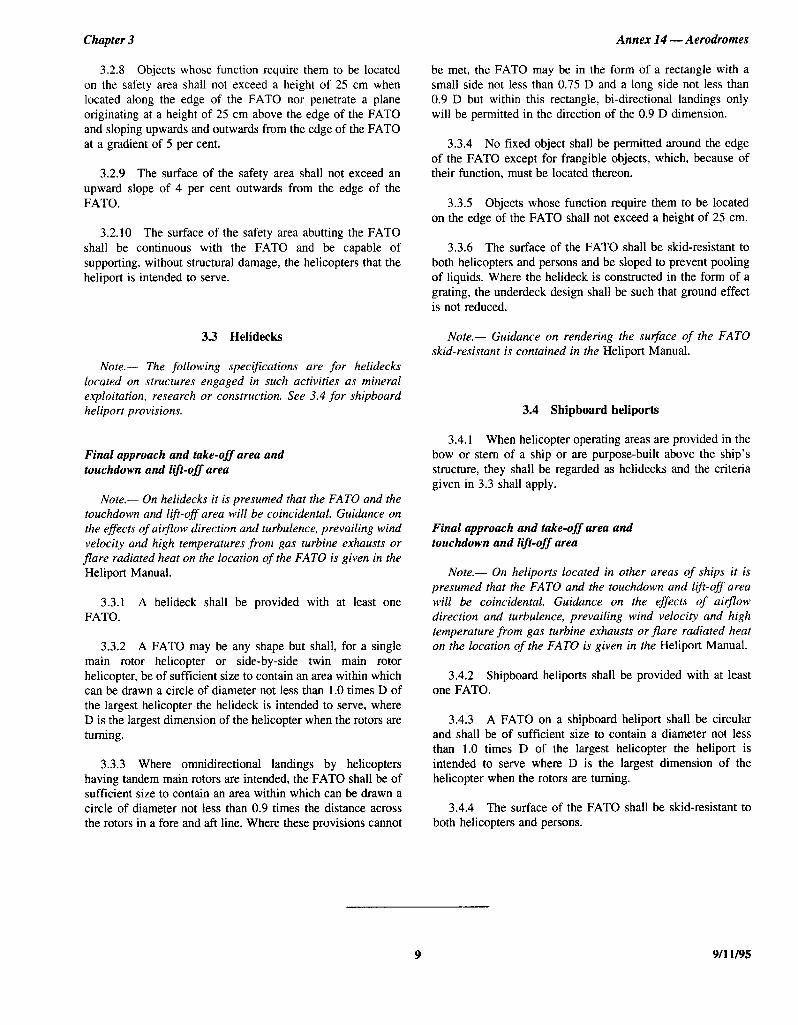
3.3 Helidecks
Note.- The following specifications are for helidecks located on structures engaged in such activities as mineral exploitation, research or construction. See 3.4 for shipboard heliport provisions.
Final approach and take-off area and touchdown and lift-off area
Note.- On helidecks it is presumed that the FAT0 and the touchdown and ltft-off area will be coincidental. Guidance on the effects of airflow direction and turbulence, prevailing wind velocity and high temperatures from gas turbine exhausts or
flare radiated heat on the location of the FAT0 is given in the Heliport Manual.
3.3.1 A helideck shall be provided with at least one FATO.
3.3.2 A FAT0 may be any shape but shall, for a single main rotor helicopter or side-by-side twin main rotor helicopter, be of sufficient size to contain an area within which can be drawn a circle of diameter not less than 1.0 times D of the largest helicopter the helideck is intended to serve, where D is the largest dimension of the helicopter when the rotors are turning.
3.3.3 Where omnidirectional landings by helicopters having tandem main rotors are intended, the FAT0 shall be of sufficient size to contain an area within which can be drawn a circle of diameter not less than 0.9 times the distance across the rotors in a fore and aft line. Where these provisions cannot
Annex 14 - Aerodromes
be met, the FAT0 may be in the form of a rectangle with a small side not less than 0.75 D and a long side not less than 0.9 D but within this rectangle, bi-directional landings only will be permitted in the direction of the 0.9 D dimension.
3.3.4 No fixed object shall be permitted around the edge of the FAT0 except for frangible objects, which, because of their function. must be located thereon.
3.3.5 Objects whose function require them to be located on the edge of the FAT0 shall not exceed a height of 25 cm.
3.3.6 The surface of the FAT0 shall be skid-resistant to both helicopters and persons and be sloped to prevent pooling of liquids. Where the helideck is constructed in the form of a grating, the underdeck design shall be such that ground effect is not reduced.
Note.- Guidance on rendering the surface of the FAT0 skid-resistant is contained in the Heliport Manual.
3.4 Shipboard heliports
3.4.1 When helicopter operating areas are provided in the bow or stern of a ship or are purpose-built above the ship’s structure, they shall be regarded as helidecks and the criteria given in 3.3 shall apply.
Final approach and take-off area and touchdown and lift-off area
Note.- On heliports located in other areas of ships it is presumed that the FAT0 and the touchdown and ltft-off area will be coincidental. Guidance on the effects of airjlow direction and turbulence, prevailing wind velocity and high temperature from gas turbine exhausts or flare radiated heat on the location of the FAT0 is given in the Heliport Manual.
3.4.2 Shipboard heliports shall be provided with at least one FATO.
3.4.3 A FAT0 on a shipboard heliport shall be circular and shall be of sufficient size to contain a diameter not less than 1.0 times D of the largest helicopter the heliport is intended to serve where D is the largest dimension of the helicopter when the rotors are turning.
3.4.4 The surface of the FAT0 shall be skid-resistant to both helicopters and persons.
9 9/l l/95

ICAO ANNEX*(/4 VOL+II *x W 4B4L4Lb 0066904 217 W
CHAPTER 4. OBSTACLE RESTRICTION AND REMOVAL
Note.- The objectives of the specij?cations in this chapter are to define the airspace around heliports to be maintained free from obstacles so as to permit the intended helicopter operations at the heliports to be conducted safely and to prevent the heliports becoming unusable by the growth of obstacles around them. This is achieved by establishing a series of obstacle limitation su$aces that define the limits to which objects may project into the airspace.
4.1 Obstacle limitation surfaces and sectors
Approach surface
4.1.4 The slope(s) of the approach surface shall be measured in the vertical plane containing the centre line of the surface.
Note.- For heliports used by pe$ormance class 2 and 3 helicopters, it is intended that approach paths be selected so as To permit safe forced landing or one-engine-inoperative landings such that, as a minimum requirement, injury lo persons on the ground or water or damage to property are minimized. Provisions for forced landing areas are expected to minimize risk of injury to the occupants of the helicopter. The most critical helicopter type for which the heliport is intended and the ambient conditions will be factors in determining the suitability of such areas.
4.1.1 Description. An inclined plane or a combination of planes sloping upwards from the end of the safety area and centred on a line passing through the centre of the FATO.
Note.- See Figure 4-l.
4.1.2 Characteristics. The limits of an approach surface shall comprise:
Transitional surface
4.1.5 Description. A complex surface along the side of the safety area and part of the side of the approach surface, that slopes upwards and outwards to the inner horizontal surface or a predetermined height.
Note.- See Figure 4-1.
a) an inner edge horizontal and equal in length to the minimum specified width of the FAT0 plus the safety area, perpendicular to the centre line of the approach surface and located at the outer edge of the safety area;
b) two side edges originating at the ends of the inner edge and:
1) for other than a precision approach FATO, diverging uniformly at a specified rate from the vertical plane containing the centre line of the FATO,
4.1.6 Characterisrics. The limits of a transitional surface shall comprise:
a) a lower edge beginning at the intersection of the side of the approach surface with the inner horizontal surface, or beginning at a specified height above the lower edge when an inner horizontal surface is not provided, and extending down the side of the approach surface to the inner edge of the approach surface and from there along the length of the side of the safety area parallel to the centre line of the FATO; and
2) for a precision approach FATO, diverging uniformly at a specified rate from the vertical plane containing the centre line of the FATO, to a specified height above FATO, and then diverging uniformly at a specified rate to a specified final width and continuing thereafter at that width for the remaining length of the approach surface; and
b) an upper edge located in the plane of the inner horizontal surface, or at a specified height above the lower edge when an inner horizontal surface is not provided.
4.1.7 The elevation of a point on the lower edge shall be:
c) an outer edge horizontal and perpendicular to the centre line of the approach surface and at a specified height above the elevation of the FATO.
a) along the side of the approach surface - equal to the elevation of the approach surface at that point; and
b) along the safety area - equal to the elevation of the centre line of the FAT0 opposite that point.
4.1.3 The elevation of the inner edge shall be the elevation of the safety area at the point on the inner edge that Note.- As a result of 6) the transitional su$ace along the is intersected by the centre line of the approach surface. safety area will be curved if the profile of the FAT0 is curved,
9/l l/95 10 ANNEX 14 - VOLUME II

ICAO ANNEX*l,4 VOL*II ~1 - YB4L41b OObb905 I153 m
Annex 14 - Aerodromes Chapter 4
or a plane if the profile is a straight line. The intersection of the transitional surface with the inner horizontal surface, or upper edge when an inner horizontal suflace is not provided, will also be a curved or a straight line depending on the profile of the FATO.
4.1.8 The slope of the transitional surface shall be measured in a vertical plane at right angles to the centre line of the FATO.
Inner horizontal surface
Note.- The intent of the inner horizontal surface is to allow safe visual manoeuvring.
4.1.9 Description. A circular surface located in a horizontal plane above a FAT0 and its environs.
Note.- See Figure 4-l.
4.1.10 Characteristics. The radius of the inner horizontal surface shall be measured from the mid-point of the FATO.
4.1.11 The height of the inner horizontal surface shall be measured above an elevation datum established for such purpose.
Note.- Guidance on determining the elevation datum is contained in the Heliport Manual.
Conical surface
4.1.12 Description. A surface sloping upwards and outwards from the periphery of the inner horizontal surface, or from the outer limit of the transitional surface if an inner horizontal surface is not provided.
Note.- See Figure 4-l.
4.1.13 Characteristics. The limits of the conical surface shall comprise:
a) a lower edge coincident with the periphery of the inner horizontal surface, or outer limit of the transitional surface if an inner horizontal surface is not provided; and
b) an upper edge located at a specified height above the inner horizontal surface, or above the elevation of the lowest end of the FAT0 if an inner horizontal surface is not provided.
4.1.14 The slope of the conical surface shall be measured above the horizontal.
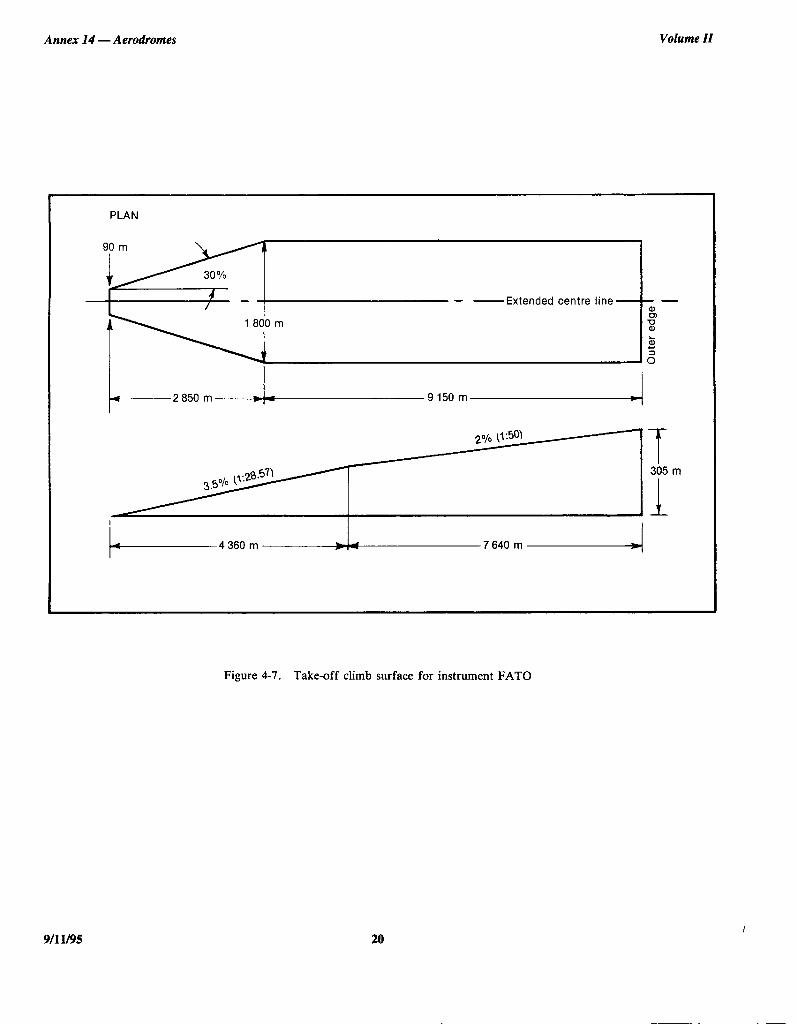
Take-off climb surface
4.1.15 Description. An inclined plane, a combination of planes or, when a turn is involved, a complex surface sloping upwards from the end of the safety area and centred on a line passing through the centre of the FATO.
Note.- See Figure 4-1.
4.1.16 Characteristics. The limits of a take-off climb surface shall comprise:
a) an inner edge horizontal and equal in length to the minimum specified width of the FAT0 plus the safety area, perpendicular to the centre line of the take-off climb surface and located at the outer edge of the safety area or clearway;
b) two side edges originating at the ends of the inner edge and diverging uniformly at a specified rate from the vertical plane containing the centre line of the FATO; and
c) an outer edge horizontal and perpendicular to the centre line of the take-off climb surface and at a specified height above the elevation of the FATO.
4.1.17 The elevation of the inner edge shall be the elevation of the safety area at the point on the inner edge that is intersected by the centre line of the take-off climb surface, except that when a clearway is provided, the elevation shall be equal to the highest point on the ground on the centre line of the clearway.
4.1.18 In the case of a straight take-off climb surface, the slope shall be measured in the vertical plane containing the centre line of the surface.
4.1.19 In the case of a take-off climb surface involving a turn, the surface shall be a complex surface containing the horizontal normals to its centre line and the slope of the centre line shall be the same as that for a straight take-off climb surface. That portion of the surface between the inner edge and 30 m above the inner edge shall be straight.
4.1.20 Any variation in the direction of the centre line of a take-off climb surface shall be designed so as not to necessitate a turn of radius less than 270 m.
Note.- For heliports used by performance class 2 and 3 helicopters, it is intended that departure paths be selected so as to permit safe forced landings or one-engine-inoperative landings such that, as a minimum requirement, injury to persons on the ground or water or damage to property are minimized. Provisions for forced landing areas are expected to minimize risk of injury to the occupants of the helicopter. The most critical helicopter type for which the heliport is intended and the ambient conditions will be factors in determining the suitability of such areas.
11 9/l l/95

ICAO ANNEXxL4 VOLaII t*
Annex 14 - Aerodromes
Obstacle-free sector/surface - helidecks
4.1.21 Description. A complex surface originating at a reference point on the edge of the FAT0 of a helideck and extending to a specified distance.
4.1.22 Characteristics. An obstacle-free sector/surface shall subtend an arc of specified angle.
4.1.23 For helidecks the obstacle-free sector shall subtend an arc of 210” and extend outwards to a distance compatible with the one-engine inoperative capability of the most critical helicopter the helideck is intended to serve. The surface shall be a horizontal plane level with the elevation of the helideck except that, over an arc of 180” passing through the centre of the FATO, the surface shall be at water level, extending outwards for a distance compatible with the take-off space required for the most critical helicopter the helideck is intended to serve (see Figure 4-2).
Limited obstacle s&ace - helidecks
4.1.24 Description. A complex surface originating at the reference point for the obstacle-free sector and extending over the arc not covered by the obstacle-free sector as shown in Figures 4-3, 4-4 and 4-5 and within which the height of obstacles above the level of the FAT0 will be prescribed.
4.1.25 Characteristics. The limited obstacle surface shall not subtend an arc greater than a specified angle and shall be sufficient to include that area not covered by the obstacle-free sector.
4.2 Obstacle limitation requirements
Note.- The requirements for obstacle limitation St&aces are specified on the basis of the intended use of a FATO, i.e. approach manoeuvre to hover or landing, or take-off manoeuvre and type of approach, and are intended to be applied when such use is made of the FATO. In cases where operations are conducted to orfrom both directions of a FATO, then the function of certain sulfates may be nullified because of more stringent requirements of another lower surface.
Surface level heliports
4.2.1 The following obstacle limitation surfaces shall be established for a precision approach FATO:
a) take-off climb surface:
b) approach surface;
c) transitional surfaces; and
d) conical surface.
- 484L4Lb OObb=lOb 09T m
Volume II
4.2.2 The following obstacle limitation surfaces shall be established for a non-precision approach FATO:
a) take-off climb surface;
b) approach surface;
c) transitional surfaces; and
d) conical surface if an inner horizontal surface is not provided.
4.2.3 The following obstacle limitation surfaces shall be established for a non-instrument FATO:
a) take-off climb surface; and
b) approach surface.
4.2.4 Recommendation.- The following obstacle limitation surfaces should be established for a non-precision approach FATO:
a) inner horizontal sulfate; and
6) conical surface.
Note.- An inner horizontal surface may not be required tf a straight-in non-precision approach is provided at both ends.
4.2.5 The slopes of the surfaces shall not be greater than, and their other dimensions not less than those specified in Tables 4-l to 4-4 and shall be located as shown in Figures 4-6 to 4-10.
4.2.6 New objects or extensions of existing objects shall not be permitted above any of the surfaces in 4.2.1 to 4.2.4 above except when, in the opinion of the appropriate authority, the new object or extension would be shielded by an existing immovable object.
Note.- Circumstances in which the shielding principle may reasonably be applied are described in the Airport Services Manual, Part 6.
4.2.1 Recommendation.- Existing objects above any of the surfaces in 4.2.1 to 4.2.4 above should, as far as practicable, be removed except when, in the opinion of the appropriate authority, the object is shielded by an existing immovable object or afrer aeronautical study it is determined that the object would not adversely affect the safety or signtficantly affect the regularity of operations of helicopters.
Note.- The application of curved take-off climb surfaces as specified in 4.1.19 may alleviate the problems created by objects infringing these sutiaces.
9/l l/95 12

ICAO ANNEX*KL4 VOL*II ** - 4843436 0066907 T2b m
Chapter 4
4.2.8 A surface level heliport shall have at least two take- off climb and approach surfaces, separated by not less than 150”.
4.2.9 Recommendation.- The number and orientation of take-off climb and approach surfaces should be such that the usability factor of a heliport is not less than 95 per centfor the helicopters the heliport is intended to serve.
Elevated heliports
4.2.10 The obstacle limitation requirements for elevated heliports shall conform to the requirements for surface level heliports specified in 4.2.1 to 4.2.7.
4.2.11 An elevated heliport shall have at least two take- off climb and approach surfaces separated by not less than 150”.
Helidecks
Note.- The following specifications are for helidecks located on a structure and engaged in such activities as mineral exploitation, research, or construction, but excluding heliports on ships.
4.2.12 A helideck shall have an obstacle-free sector and, where necessary, a limited obstacle sector.
4.2.13 There shall be no fixed obstacles within the obstacle-free sector above the obstacle-free surface.
4.2.14 In the immediate vicinity of the helideck, obstacle protection for helicopters shall be provided below the heliport level. This protection shall extend over an arc of at least 180” with the origin at the centre of the FATO, with a descending gradient having a ratio of one unit horizontally to five units vertically from the edges of the FAT0 within the 180” sector.
4.2.15 Where a mobile obstacle or combination of obstacles within the obstacle-free sector is essential for the operation of the installation, the obstacle(s) shall not subtend an arc exceeding 30”, as measured from the centre of the FATO.
4.2.16 For single-main-rotor and side-by-side twin rotor helicopters, within the 150” limited obstacle surface/sector out to a distance of 0.62 D, measured from the centre of the FATO, objects shall not exceed a height of 0.05 D above the FATO. Beyond that arc, out to an over-all distance of 0.83 D
Annex 14 - Aerodromes
the limited obstacle surface rises at a rate of one unit vertically for each two units horizontally (see Figure 4-3).
4.2.17 For omnidirectional operations by tandem-main- rotor helicopters within the 150” limited obstacle surface/sector out to a distance of 0.62 D, measured from the centre of the FATO, there shall be no fixed obstacles. Beyond that arc, out to an over-all distance of 0.83 D, objects shall not penetrate a level surface which has a height equivalent to 0.05 D above the FAT0 (see Figure 4-4).
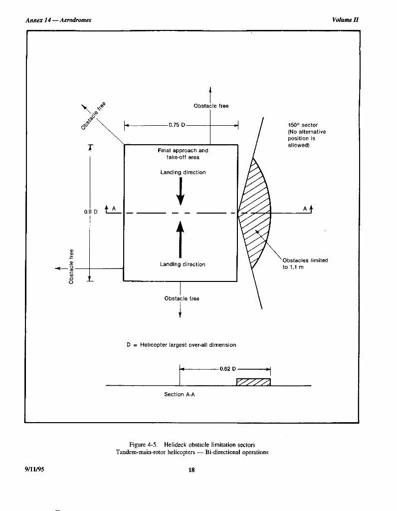
4.2.18 For bi-directional operations by tandem-main- rotor helicopters, within the 0.62 D arc in the 150” limited obstacle surface/sector, objects shall not penetrate a level surface which has a height equivalent to 1.1 m above the FAT0 (see Figure 4-5).
Shipboard heliports
Amidships location
4.2.19 Forward and aft of the FAT0 shall be two symmetrically located sectors, each covering an arc of 150”, with their apexes on the periphery of the FAT0 D reference circle. Within the area enclosed by these two sectors, there shall be no objects rising above the level of the FATO, except those aids essential for the safe operation of a helicopter and then only up to a maximum height of 25 cm.
4.2.20 To provide further protection from obstacles fore and aft of the FATO, rising surfaces with gradients of one unit vertically to five units horizontally shall extend from the entire length of the edges of the two 150” sectors. These surfaces shall extend for a horizontal distance equal to at least the diameter of the FAT0 and shall not be penetrated by any obstacle (see Figure 4-l 1).
Ship’s side location
4.2.21 From the fore and aft mid-points of the D reference circle, an area shall extend to the ship’s rail to a fore and aft distance of 1.5 times the diameter of the FATO, located symmetrically about the athwartships bisector of the reference circle. Within this sector there shall be no objects rising above the level of the FATO, except those aids essential to the safe operation of the helicopter and then only up to a maximum height of 25 cm (see Figure 4-12).
4.2.22 A horizontal surface shall be provided, at least 0.25 times the diameter of the D reference circle, which shall surround the FAT0 and the obstacle-free sector, at a height of 0.05 times the diameter of the reference circle, which no object shall penetrate.
13 9/11/95

ICAO ANNEXxL4 VOL*II *Kx - 4B4L4Lb 0066708 962 -
Annex 14 - Aerodromes Volume ZZ
Approach Take-off climb
Approach Transitional PAX Inner horizontal .............
............................. +-Conical 3 ......................... .............. ............................. ............................... ................. I. ...... 1:. ................. .................. ....................
: .... ..I I.. -Y \(q
............ .................................. ..................
............................................................................ --.-ILL/” . . ................. 3 ................... ................................................................................................................. ................................................................................................................. ...... ........................................................ ..~.~.~.......~.~ ......
-c FAT0
Section B-B
Note.- The figure shows the obstacle limitation surfaces at a heliport with a non-precision approach FAT0 and a clearway.
9/l l/95
Figure 4- 1. Obstacle limitation surfaces
14

ICAO ANNEXxL4 VOL*II tX - 484L4Lb 0066909 BT=l m
Chapter 4 Annex I4 - Aerodromes
210° sector
Alternative positions on the periphery and swinging the whole sector f 151~ from that shown may be used in satisfying requirements
de PLAN
CJtda 1 il?!lted. ..n
\180° sector 1
PROFILE
Landina area Within 210° sector no obiects above this line
No fixed obstacle between these lines in 180° sector in 180° sector
No fixed obstacle between these lines in 180°
Water level Water level
Figure 4-2. Helideck obstacle-free sector
15 9/l l/95

ICA() ANNEX*lY voL*II ** - 484143b 0066930 5l,O m
Annex 14 - Aerodromes Volume II
150° sector (Alternative positions on the periphery and swinging the whole sector f 1CP from that shown may be used in satisfying requirements)
Obstacle free I
Final approach and take-off area
A ,Obstacles limited
I D = Helicopter largest over-all dimension
’ ;\-
Obstacle free
+ 150
0.83 0.
0.62 D-
Section AA
Figure 4-3. Helideck obstacle limitation sectors Single-main-rotor and side-by-side twin rotor helicopters
9/l l/95 16

ICAO ANNEXxL4 VOLXII X* - 48414Lb OObb91L 457 m
Chapter 4 Annex 14 - Aerodromes
Obstacle free
Final approach and take-off area
A - -- /
-- 8
-s z
I D = Helicopter largest over-all dimension
I Obstacle free
150° sector (Alternative positions on the periphery and swinging the whole sector * 15O from that shown may be used in satisfying requirements)
limited
+
Section AA
0.83 D-
0.62 D-
P///A
Figure 4-4. Helideck obstacle limitation sectors Tandem-main-rotor helicopters - Omnidirectional operations
17 9/l l/95
ICAO ANNEX*L4 VOLvII t* - 484L4ltb 0066932 373 -
Annex 14 - Aerodromes Volume II
~ 0.75D obsta[free -t Final approach and
take-off area
1
Landing direction
150° sector (No alternative position is allowed)
- --
Landing direction
I Obstacle free
D = Helicopter largest over-ail dimension
Obstacles limited
Section A-A
Figure 4-5. Helideck obstacle limitation sectors Tandem-main-rotor helicopters - Bi-directional operations
9/l l/95 18

ICAO ANNEXxL4 VOLXII ** - 413YL4bb 0066933 22T m
Chapter 4 Annex 14 - Aerodrotnes
Final al tak&nff
Take-off climb/ approach surface
Shaded area to have same characteristics as safety area
A. Circular final approach and take-off area (straight approach-departure)
Take-off climb/
I
,&p
.::.
/ ;:
FAT0 Safety Safety
Shaded area to have same characteristics as safety area
area area
B. Squared final approach and take-off area (straight approach-departure)
I 1 Final approach/take-off area
.
Safety area
C. Squared final approach and take-off area (curved approach-departure)
y Final width +
Figure 4-6. Take-off climb/approach surface (non-instrument FATO)
19
ICAO ANNEX*l,Lt VOLrII ** - YB4L4Lb 0066914 Lbb m
Annex 14 - Aerodromes Volume ZZ
PLAN PLAN
- -Extended centre line - -Extended centre line - - a a
z z
/f 305 m 305 m
1
Figure 4-7. Take-off climb surface for instrument FAT0
9/l l/95 20

Chapter 4
ICAO ANNEX+LY VOLrII *cf - 48414Lb OObb=lLS OT2 W
Annex Z4 - Aerodromes
PLAN
Extended centre line
I
* IOOOOm~J
I-3000 m A2 500 m-L-4 500 m ~-4
PROFILE - 6” approach Horizontal * t
\D 150 m
Ll 500 rn.-&-1250 m-i,/5750 rnd
Figure 4-8. Approach surface for precision approach FAT0
21 9/11/995
Annex 14 - Aerodromes
ICAO ANNEX*:L4 VOL*II tt - 48414Lb OObb9ltb T37 m
Volume ZZ
PLAN
90 m
11 \
16% Extended centre line - -
PROFILE
I 1 , ;
I -1 7
83.3 m
I.2500 m 8
)m
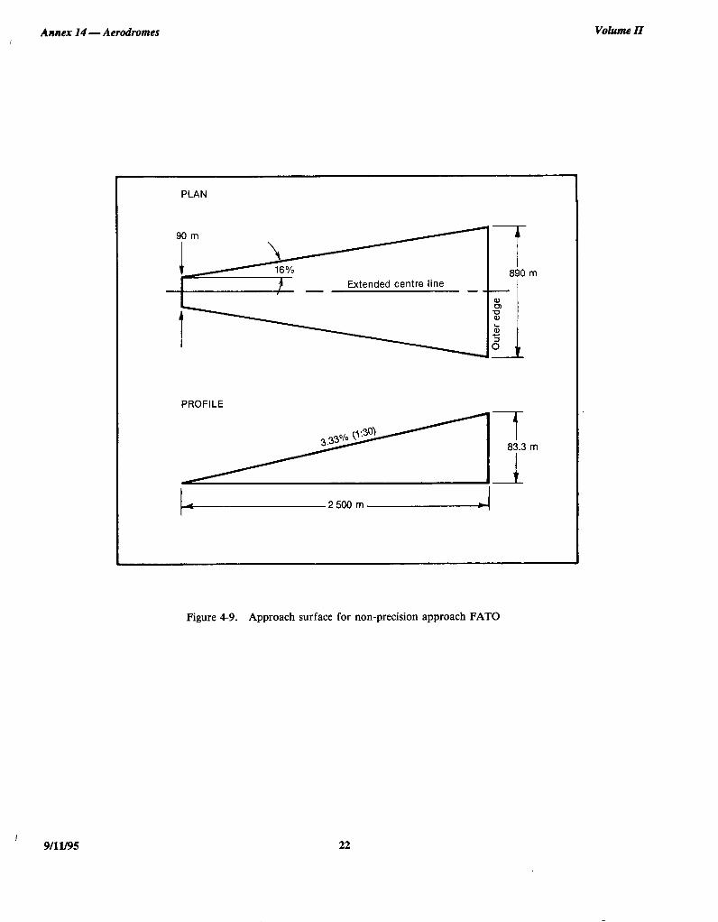
Figure 4-9. Approach surface for non-precision approach FAT0
I 9/1l/95 22

Chapter 4 Annex 14 - Aerodromes
ICAO ANNEX*14 VOLXII ** - 484LYLb 0066937 975 m
r Conical surface
Transitional surface -
100 m
45 m
1100m
L-315 m--j 4 000 m
Non-precision approach (end profiles)
b-315 m&------i 100 me
Alternative when no inner horizontal surface is provided
Precision approach (end profiles)
Figure 4-10. Transitional, inner horizontal and conical obstacle limitation surfaces
23 9/11/95

ICAO ANNEXSlY VOL*II ** - 484LYLb OObb=l38 801 m
Annex I4 - Aerodromes Volume ZZ
r;;srtacl\, Obstacle-free sector /Limit;~&;tac&/
PLAN VIEW
D = Helicopter largest over-all dimension
-D-
Section A-A
Figure 4-l 1. Midship non-purpose built heliport obstacle limitation surfaces
9/l l/95 24

Chapter 4
ICAO ANNEX*lt4 VOL*II tt m 484LYLb 0066939 748 -
Annex 14 - Aerodromes
Limited obstacle sector maximum height 0.05 D
1.5 D
Obstacle-free sector
D = Helicopter largest over-all dimension
Figure 4-12. Ships-side non-purpose built heliport obstacle limitation surfaces
25 9/l 1195

ICAO ANNEX*14 VOLXII t* - 4841416 OObb'720 4bT m
Annex 14 - Aerodromes Volume ZZ
Table 4-1. Dimensions and slopes of obstacle limitation surfaces
NON-INSTRUMENT AND NON-PRECISION FAT0
Surface and dimensions
Non-instrument (visual) FAT0 Non-precision (instrument
Helicopter performance class approach) 1 2 3 FAT0
APPROACH SURFACE Width of inner edge Location of inner edge
Width of safety area Boundary
Width of safety area Boundary
First section Divergence - day
- night - day - night - day - night
10% 15%
245 ma 245 ma 49 mb
73.5 mb 8%B
10% 15%
245 ma 245 ma 49 mb
13.5 mb 8%a
10% 15%
245 ma 245 ma 49 mb
73.5 mb 8%”
16%
25OOm
890 m
3.33%
Length
Outer width
Slope (maximum)
Second section Divergence - day
- night - day - night - day - night
10% 15%
c c d
d
12.5%
10% 15%
c c d d
12.5%
10% 15%
E E d
d
12.5%
Length -
Outer width -
Slope (maximum) -
Third section Divergence Length
parallel e e d
d
15%
parallel e e d
d
15%
parallel e e d
d
15%
- day - night - day - night
Outer width
Slope (maximum)
INNER HORIZONTAL Height Radius
45 m 2000m
- - -
- - -
CONICAL Slope Height
5% 55 m
- -
- -
TRANSITIONAL Slope Height
20% 45 m
- - - - - -
a. Slope and length enables helicopters to decelerate for landing while observing “avoid” areas. b. The width of the inner edge shall be added to this dimension. c. Determined by the distance from the inner edge to the point where the divergence produces a width of 7 rotor diameters for day operations or
10 rotor diameters for night operations. d. Seven rotor diameters over-all width for day operations or 10 rotor diameters over-all width for night operations. e. Determined by the distance from inner edge to where the approach surface reaches a height of 150 m above the elevation of the inner edge.
9/l If95 26

ICAO ANNEX*l,4 VOL*II t* W 484L4Lb OObb92L 3Tb H
Chapter 4
Table 4-2. Dimensions and slopes of obstacle limitation surfaces
INSTRUMENT (PRECISION APPROACH) FAT0
Annex 14 - Aerodromes
Surface and dimensions
APPROACH SURFACE
Length of inner edge
Distance from end of FAT0
Divergence each side to height above FAT0
Distance to height above FAT0
Width at height above FAT0
Divergence to parallel section
Distance to parallel section
Width of parallel section
Distance to outer edge
Width at outer edge
Slope of first section
3” approach
Height above FAT0
60 m 45 m (200 ft) (150 ft)
30 m (looft)
6’ approach
Height above FAT0
60m 45 m 30m (200 ft) (150 ft) (loo ft)
90m 90 m
60 m
25%
90 m
60 m
25%
90m 90m 90m 90 m 90 m
60m 60 m 60 m 60 m 60m 60m
25% 25% 25% 25% 25% 25%
1745 m
962 m
15%
1163m
671 m
15%
872 m
526 m
15%
581 m
380 m
15%
870 m
521 m
15%
2793m 3 763 m 4 246 m 4 733 m 4250m
435 m
307.5 m
15%
4 975 m
18OOm 18OOm 18OOm 18OOm 18OOm
580 m
380 m
15%
4 733 m
18OOm
290 m
235 m
15%
5 217 m
18OOm 18OOm
5 462 m 5 074 m 4882m 4686m 3380m 3 187m 3090m
18OOm 18OOm 18OOm 1800m 18OOm 18OOm 18OOm
2.5% (1:40)
2.5% (1:40)
2.5% (1:40)
2.5% (1:40)
2 993 m
18OOm
5% (1:20)
Length of first section 3000m
Slope of second section 3% (1:33.3)
Length of second section 2500m
Total length of surface 1OOOOm
CONICAL Slope Height
5% 55 m
TRANSITIONAL Slope Height
14.3% 45 m
1500m
6% (1:16.66)
3000m
3% (1:33.3)
3000m
3% (1:33.3)
3000m
3% (1:33.3)
15OOm
6% (1:16.66)
1500m
(Z66)
1500m
6% (1:16.66)
2500m
10OOOm
2500m
1OOOOm
2500m
10OOOm
1 250 m
8500m
1250m
8500m
1 250 m
8500m
1250m
8500m
5% 55 m
5% 55 m
5% 55 m
5% 55 m
5% 55 m
5% 55 m
5% 55 m
14.3% 45 m
14.3% 45 m
14.3% 45 m
14.3% 45 m
14.3% 45 m
14.3% 45 m
14.3% 45 m
27 9/l l/95

ICAO ANNEX*l,4 VOL*II ** - 484L41b 0066922 232 m
Annex 14 - Aerodromes Volume ZZ
Table 4-3. Dimensions and slopes of obstacle limitation surfaces
STR4IGHT TAKE-OFF
Non-instmment (visual)
Surface and dimensions Helicopter performance class
1 2 3 Instrument
TAKE-OFF CLIMB
Width of inner edge Location of inner edge
Width of safety area Boundary or end of clearway
90 m Boundary or
end of clearway
First section
Divergence - day - night
10% 10% 15% 15%
10% 15%
30%
a 245 mb a 245 mb
Length - day - night
245 mb 245 mb
2850m
49 md 73.5 md
Outer width - day - night
Slope (maximum)
Second section
c 49 md c 73.5 md
18OOm
4.5%* 8%b 8%b 3.5%
Divergence - day - night
parallel parallel
10% 15%
10% 15%
parallel
Length - day - night
e a a 1510m e a a
Outer width c c c 18OOm c c c
- day - night
Slope (maximum) 4.5%* 15% 15% 3.5%*
Third section
Divergence - parallel parallel parallel
- day - night
Length - e e 7 640 m - e e
Outer width - c c 18OOm - c c
- day - night
Slope (maximum) - 15% 15% 2%
a. Determined by the distance from the inner edge to the point where the divergence produces a width of 7 rotor diameters for day operations or 10 rotor diameters for night operations.
b. Slope and length provides helicopters with an area to accelerate and climb while observing “avoid” areas. c. Seven rotor diameters over-all width for day operations or 10 rotor diameters over-all width for night operations. d. The width of the inner edge shall be added to this dimension. e. Determined by the distance from the inner edge to where the surface reaches a height of 150 m above the elevation of the inner edge.
* This slope exceeds the maximum mass one-engine-inoperative climb gradient of many helicopters which are currently operating.
9/l II95 28

Chapter 4 Annex 14 - Aerodromes
ICAO ANNEX*c14 VOL*II ** - 484L4Lb OObb723 177 m
Table 4-4. Criteria for curved take-off climb/approach area
NON-INSTRUMENT FINAL APPROACH AND TAKE-OFF
Facility Requirement
Directional change
Radius of turn on centre line
Distance to inner gate*
Width of inner gate - day
- night
Width of outer gate - day
- night
Elevation of inner and outer gates
Slopes
Divergence
Total length of area
As required (120” max).
Not less than 270 m.
(a) For performance class 1 helicopters - not less than 305 m from the end of the safety area or helicopter clearway.
(b) For performance class 2 and 3 helicopters - not less than 370 m from the end of the FATO.
Width of the inner edge plus 20% of distance to inner gate.
Width of the inner edge plus 30% of distance to inner gate.
Width of inner edge plus 20% of distance to inner gate out to minimum width of 7 rotor diameters.
Width of inner edge plus 30% of distance to inner gate out to a minimum width of 10 rotor diameters.
Determined by the distance from the inner edge and the designated gradient(s).
As given in Tables 4- 1 and 4-3.
As given in Tables 4- 1 and 4-3.
As given in Tables 4-1 and 4-3.
* This is the minimum distance required prior to initiating a turn after take-off or completing a turn in the final phase.
Note.- More than one turn may be necessary in the total length of the take-off climb/approach area. The same criteria will apply for each subsequent turn except that the widths of the inner and outer gates will normally be the maximum width of the area.
29 9/l 1195

IC/!,O ANNEX*L4 Vot.*II ** - 484L4Lb 0066724 005 m
CHAPTER 5. VISUAL AIDS
5.1 Indicators
5.1.1 Wind direction indicators
Application
5.1 .l. 1 A heliport shall be equipped with at least one wind direction indicator.
Location
5.1.1.2 A wind direction indicator shall be located so as to indicate the wind conditions over the final approach and take-off area and in such a way as to be free from the effects of aifflow disturbances caused by nearby objects or rotor downwash. It shall be visible from a helicopter in flight, in a hover or on the movement area.
5.1.1.3 Recommendation.- Where a touchdown and lift-off area may be subject to a disturbed air flow, then additional wind direction indicators located close to the area should be provided to indicate the su$ace wind on the area.
Note.- Guidance on the location of wind direction indicators is given in the Heliport Manual.
Characteristics
5.1.1.4 A wind direction indicator shall be constructed so that it gives a clear indication of the direction of the wind and a general indication of the wind speed.
5.1.1.5 Recommendation.- An indicator should be a truncated cone made of lightweight fabric and should have the
following minimum dimensions:
Length
Diameter (larger end)
Surface level Elevated heliports heliports and helidecks
2.4 m 1.2 m
0.6 m 0.3 m
Diameter (smaller end)
0.3 m 0.15 m
5.1.1.6 Recommendation.- The colour of the wind direction indicator should be so selected as to make it clearly visible and understandable from a height of at least 200 m (650 ft) above the heliport, having regard to background. Where practicable, a single colour, preferably white or orange, should be used. Where a combination of two colours is required to give adequate conspicuity against changing backgrounds, they should preferably be orange and white, red and white, or black and white, and should be arranged in five alternate bands thefirst and last band being the darker colour.
5.1.1 .I A wind direction indicator at a heliport intended for use at night shall be illuminated.
5.2 Markings and markers
Note.- See Annex 14, Volume I, 5.2.1.4, Note I, concerning improving conspicuity of markings. .
5.2.1 Winching area marking
Application
5.2.1.1 Recommendation.- A winching area marking should be provided at a winching area.
Location
5.2.1.2 A winching area marking shall be located so that its centre coincides with the centre of the clear zone of the winching area.
Chamcteristics
5.2.1.3 A winching area marking shall consist of a solid circle of not less than 5 m in diameter and painted yellow.
5.2.2 Heliport identification marking
Application
5.2.2.1 A heliport identification marking shall be provided at a heliport.
9/l l/95 30 ANNEX 14 - VOLUME II

ICAO ANNEX*:/4 VOL*II fS - 4843436 OObb725 T4L -
Chapter 5 Annex 14 - Aerodromes
-
t-3ml T
I--- 3m 4 rl.8 ml ’
E
f
Hf f ; 7
-- -- , + ;- -- 4
l-l 04m
L-J Figure 5- 1. Heliport identification marking (shown with
hospital cross and orientation with obstacle-free sector)
Location
5.2.2.2 A heliport identification marking shall be located within the final approach and take-off area, at or near the centre of the area or when used in conjunction with runway designation markings at each end of the area.
Characteristics
5.2.2.5 A heliport identification marking shall be oriented with the cross arm of the H at right angles to the preferred final approach direction. For a helideck the cross arm shall be on or parallel to the bisector of the obstacle-free sector as shown in Figure 5-l.
5.2.2.3 A heliport identification marking, except for a heliport at a hospital, shall consist of a letter H, white in colour. The dimensions of the marking shall be no less than those shown in Figure 5-l and where the marking is used in conjunction with the final approach and take-off area designation marking specified in 52.5 its dimensions shall be increased by a factor of 3.
5.2.3 Maximum allowable mass marking
Application
Note.- On a helideck covered with a rope netting, it may 5.2.3.1 Recommendation.- A maximum allowable mass be advantageous to increase the height of the marking to 4 m marking should be displayed at an elevated heliport and at a and the other dimensions proportionally. helideck.
5.2.2.4 A heliport identification marking for a heliport at a hospital shall consist of a letter H, red in colour, on a white cross made of squares adjacent to each of the sides of a square containing the H as shown in Figure 5- 1.
31 9/l l/95

ICAO ANNEX*14 VOL*II ** - 48414Lb 0066926 788 m
Annex 14 - Aerodromes Volume II
Location 5.2.4.5 A final approach and take-off area marking shall be white.
5.2.3.2 Recommendation.- A maximum allowable mass marking should be located within the touchdown and ltft-off area and so arranged as to be readable from the preferred final approach direction. 5.2.5 Final approach and take-off area
designation marking
Characteristics Application
5.2.3.3 A maximum allowable mass marking shall consist of a two digit number followed by a letter “t” to indicate the allowable helicopter mass in tonnes (1 000 kg).
5.2.3.4 Recommendation.- The numbers and the letter of the marking should have a colour contrasting with the background and should be in the form and proportion shown in Figure 5-2.
5.2.5.1 Recommendation.- A final approach and take- off area designation marking should be provided where it is necessary to designate the final approach and take-off area to the pilot.
Location
5.2.4 Final approach and take-off area marking or marker
5.2.5.2 A final approach and take-off area designation marking shall be located at the beginning of the final approach and take-off area as shown in Figure 5-3.
Application Characteristics
5.2.4.1 Final approach and take-off area marking or markers shall be provided at a surface level heliport on ground where the extent of the final approach and take-off area is not self-evident.
5.2.5.3 A final approach and take-off area designation marking shall consist of a runway designation marking described in Annex 14, Volume I, 5.2.2.4 and 5.2.2.5 supplemented by an H, specified in 5.2.2 above, and as shown in Figure 5-3.
Location
5.2.4.2 Final approach and take-off area marking or markers shall be located on the boundary of the final approach and take-off area.
5.26 Aiming point marking
Application Characteristics
5.2.4.3 Final approach and take-off area marking or markers shall be spaced:
5.2.6.1 Recommendation.- An aiming point marking should be provided at a heliport where it is necessary for a pilot to make an approach to a particular point before proceeding to the touchdown and lifr-off area.
a) for a square or rectangular area at equal intervals of not more than 50 m with at least three markings or markers on each side including a marking or marker at each corner; and Location
b) for any other shaped area, including a circular area, at equal intervals of not more than 10 m with a minimum number of five markings or markers.
5.2.6.2 The aiming point marking shall be located within the final approach and take-off area.
5.2.4.4 A final approach and take-off area marking shall be a rectangular stripe with a length of 9 m or one-fifth of the side of the final approach and take-off area which it defines and a width of 1 m. Where a marker is used its characteristics shall conform to those specified in Annex 14, Volume I, 5.5.8.3 except that the height of the marker shall not exceed 25 cm above ground or snow level.
Characteristics
5.2.6.3 The aiming point marking shall be an equilateral triangle with the bisector of one of the angles aligned with the preferred approach direction. The marking shall consist of continuous white lines and the dimensions of the marking shall conform to those shown in Figure 5-4.
9/l l/95 32

Chapter 5
ICAO ANNEX*:/4 VOLXII XX - 4843436 0066727 BL4 m
Annex 14 - Aerodromes
Note.- All units are expressed in centimetres.
Figure 5-2. Form and proportions of numbers and letter for maximum allowable mass marking
33 9/11/95

ICAO ANNEX*14 VOLXII tX - 484lltLb 0066928 750 m
Annex 14 - Aerodromes
Figure 5-3. Final approach and take-off area designation marking
Figure 5-4. Aiming point marking
5.2.7 Touchdown and lift-off area marking
Application
Location
Volume II
5.2.7.3 The touchdown and lift-off area marking shall be located along the perimeter of the touchdown and lift-off area.
5.2.7.1 A touchdown and lift-off area marking shall be provided on a helideck.
Characteristics 5.2.7.2 Recommendation.- A touchdown and @-off
urea marking should be provided on a heliport other than a 5.2.7.4 A touchdown and lift-off area marking shall helideck if the perimeter of the touchdown and lift-off area is consist of a continuous white line with a width of at least not self-evident. 30 cm.
9/l l/95 34

. ICAO ANNEX*(/'i VOLXII tX H
Chapter 5
5.2.8 Touchdown marking
Application
5.2.8.1 Recommendation.- A touchdown marking should be provided where it is necessary for a helicopter to touch down in a specific position.
Location
5.2.8.2 A touchdown marking shall be located so that when a helicopter for which the marking is intended is positioned, with the main undercarriage inside the marking and the pilot situated over the marking, all parts of the helicopter will be clear of any obstacle by a safe margin.
5.2.8.3 On a helideck or on an elevated heliport the centre of the touchdown marking shall be located at the centre of the touchdown and lift-off area except that the marking may be offset away from the origin of the obstacle-free sector by no more than 0.1 D where an aeronautical study indicates such offsetting to be necessary and that a marking so offset would not adversely affect the safety.
Characteristics
5.2.8.4 A touchdown marking shall be a yellow circle and have a line width of at least 0.5 m. For a helideck the line width shah be at least 1 m.
5.2.8.5 On helidecks the inner diameter of the circle shall be half the D value of the helideck or 6 m whichever is the greater.
5.2.9 Heliport name marking
Application
5.2.9.1 Recommendation.- A heliport name marking should be provided at a heliport where there is insuficient alternative means of visual identification.
Location
5.2.9.2 Recommendation.- The heliport name marking should be placed on the heliport so as to be visible, as far as practicable, at all angles above the horizontal. Where an obstacle sector exists the marking should be located on the obstacle side of the H identification marking.
Annex 14 - Aerodromes
Characteristics
5.2.9.3 A heliport name marking shah consist of the name or the alphanumeric designator of the heliport as used in the R/T communications.
5.2.9.4 RecommendatiorL- The characters of the marking should be not less than 3 m in height at surface level heliports and not less than 1.2 m on elevated heliports and helidecks. The colour of the marking should contrast with the background.
5.2.9.5 A heliport name marking intended for use at night or during conditions of poor visibility shah be illuminated, either internally or externally.
5.2.10 Helideck obstacle-free I sector marking
Application
5.2.10.1 Recommendation.- A helideck obstacle-free sector marking should be provided at a helideck.
Location
5.2.10.2 A helideck obstacle-free sector marking shah be located on the touchdown and lift-off area marking.
Characteristics
5.2.10.3 The helideck obstacle-free sector marking shall indicate the origin of the obstacle free sector, the directions of the limits of the sector and the D value of the helideck as shown in Figure 5-5 for a hexagonal-shaped helideck.
Note.- D is the largest dimension of the helicopter when the rotors are turning.
5.2.10.4 The height of the chevron shall equal the width of the touchdown and lift-off area marking.
5.2.10.5 The chevron shall be black.
5.2.11 Marking for taxiways
Note.- The specifications for taxiway centre line marking and taxi-holding position markings in Annex 14, Volume I, 5.2.8 and 52.9 are equally applicable to taxiways intended for ground taxiing of helicopters.
cot-r. 35 9/l 1195 20110/95

ICAO ANNEX*14 voL*:II ** - 4841416 l.JOb~O~~ 458 m l
Annex 14 - Aerodrornes
5.2.12 Air taxiway markers
Application
5.2.12.1 Recommendation.- An air taxiway should be marked with air taxiway markers.
Note.- These markers are not meant to be used on helicopter ground taxiways.
Location
5.2.12.2 Air taxiway markers shall be located along the centre line of the air taxiway and shall be spaced at intervals of not more than 30 m on straight sections and 15 m on curves.
Characteristics
5.2.12.3 An air taxiway marker shall be frangible and when installed shall not exceed 35 cm above ground or snow
Volume II
be a rectangle with a height to width ratio of approximately 3 to 1 and shall have a minimum area of 150 cm’ as shown in Figure 5-6.
5.2.12.4 An air taxiway marker shall be divided into three equal, horizontal bands coloured yellow, green and yellow, respectively. If the air taxiway is to be used at night, the markers shall be internally illuminated or retro-reflective.
5.2.13 Air transit route markers
Application
5.2.13.1 Recommendation.- When established an air transit route should be marked with air transit route markers.
* Location
5.2.13.2 Air transit route markers shall be located along the centre line of the air transit route and shall be spaced at intervals of not more than 60 m on straight sections and 15 m
level. The surface of the marker as viewed by the pilot shall on curves.
l- --------------------- -I
I Obstacle sector I I
Touchdown and lift-off
Touchdown and lift-off area marking
60 cm
9/l l/95
Figure 5-5. Helideck obstacle-free sector marking
36

Chapter 5
ICAO ANNEX*l'i VOLaII bt m LtBltL4Lb 0066933 245 m
Annex 14 - Aerodromes
approx.
H-i
Figure 5-6. Air taxiway marker
Example A Example B
Figure 5-7. Air transit route marker
37 9/l l/95
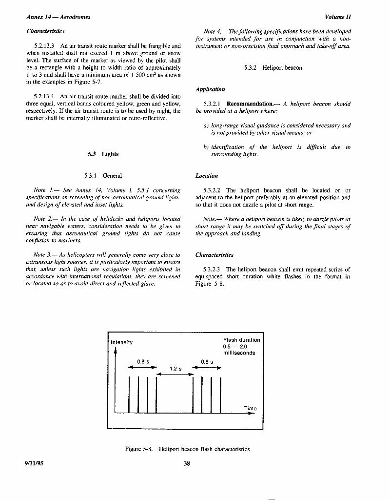
ICAO ANNEX+lt4 VOLrII Xb m 4843436 OObb932 1Bl, m
Annex 14 - Aerodromes Volume II
Characteristics
5.2.13.3 An air transit route marker shall be frangible and when instabed shall not exceed 1 m above ground or snow level. The surface of the marker as viewed by the pilot shall be a rectangle with a height to width ratio of approximately 1 to 3 and shall have a minimum area of 1 500 cm2 as shown in the examples in Figure 5-7.
5.2.13.4 An air transit route marker shall be divided into three equal, vertical bands coloured yellow, green and yellow, respectively. If the air transit route is to be used by night, the marker shall be internally illuminated or retro-reflective.
5.3 Lights
5.3.1 General
Note I.- See Annex 14, Volume I, 53.1 concerning spec:j?cations on screening of non-aeronautical ground lights. and design of elevated and inset lights.
Note 2.- In the case of helidecks and heliports located near navigable waters, consideration needs to be given to ensuring that aeronautical ground lights do not cause confusion to mariners.
Note 3.- As helicopters will generally come very close to extraneous light sources, it is particularly important to ensure that, unless such lights are navigation lights exhibited in accordance with international regulations, they are screened or located so as to avoid direct and reflected glare,
Note 4.- The following specifications have been developed for systems intended for use in conjunction with a non- instrument or non-precision final approach and take-off area.
5.3.2 Heliport beacon
Application
5.3.2.1 Recommendation.- A heliport beacon should be provided at a heliport where:
a) long-range visual guidance is considered necessary and is not provided by other visual means; or
b) identification of the heliport is dtflcult due to surrounding lights.
Location
5.3.2.2 The heliport beacon shall be located on or adjacent to the heliport preferably at an elevated position and so that it does not dazzle a pilot at short range.
Note.- Where a heliport beacon is likely to daz$e pilots at short range it may be switched off during the final stages of the approach and landing.
Characteristics
5.3.2.3 The heliport beacon shall emit repeated series of equispaced short duration white flashes in the format in Figure 5-8.
Flash duration 0.5 - 2.0 milliseconds
Time t
Figure 5-8. Heliport beacon flash characteristics
38 9/l l/95

Chapter 5
5.3.2.4 The light from the beacon shall show at all angles of azimuth.
5.3.2.5 Recommendation.- The effective light intensity distribution of each flash should be as shown in Figure 5-9, illustration 1.
Note.- Where brilliancy control is desired, settings of IO per cent and 3 per cent have been found to be satisfactory. In addition, shielding may be necessary to ensure that pilots are not dazzled during the final stages of the approach and landing.
5.3.3 Approach lighting system
Application
5.3.3.1 Recommendation.- An approach lighting system should be provided at a heliport where it is desirable and practicable to indicate a preferred approach direction.
LQClltiO?l
5.3.3.2 The approach lighting system shall be located in a straight line along the preferred direction of approach.
Characteristics
5.3.3.3 Recommendation.- An approach lighting system should consist of a row of three lights spaced untformly at 30 m intervals and of a crossbar 18 m in length at a distance of 90 m from the perimeter of the final approach and take-off area as shown in Figure 5-10. The lights forming the crossbar should be as nearly as practicable in a horizontal straight line at right angles to, and bisected by, the line of the centre line lights and spaced at 4.5 m intervals. Where there is the need to make the final approach course more conspicuous additional lights spaced untformly at 30 m intervals should be added beyond the crossbar. The lights beyond the crossbar may be steady or sequenced jlashing, depending upon the environment.
Note.- Sequenced flashing lights may be useful where identification of the approach lighting system is difSicult due to surrounding lights.
5.3.3.4 Recommendation.- Where an approach lighting system is provided for a non-precision &al approach and take-off area, the system should not be less than 210 m in length.
5.3.3.5 The steady lights shall be omnidirectional white lights.
Annex 14 - Aerodromes
5.3.3.6 Recommendation.- The light distribution of steady lights should be as indicated in Figure 5-9, Illus- tration 2 except that the intensity should be increased by a
factor of 3 for a non-precision final approach and take-off area.
5.3.3.7 Sequenced flashing lights shall be omnidirectional white lights.
5.3.3.8 Recommendation.- The flashing lights should have a flash frequency of one per second and their light distribution should be as shown in Figure 5-9, Illustration 3. The flash sequence should commence from the outermost light and progress towards the crossbar.
5.3.3.9 Recommendation.- A suitable brilliancy control should be incorporated to allow for adjustment of light intensity to meet the prevailing conditions.
Note.- The following intensity settings have been found suitable:
a) steady lights - 100 per cent, 30per cent and loper cent; and
b) flashing lights - looper cent, loper centand3per cent.
5.3.4 Visual alignment guidance system
Application
5.3.4.1 Recommendation.- A visual alignment guidance system should be provided to serve the approach to a heliport where one or more of the following conditions exist especially at night:
a} obstacle clearance, noise abatement or trafic control procedures require a particular direction to be flown;
b) the environment of the heliport provides few visual sutiace cues; and
c) it is physically impracticable to install an approach lighting system.
Location
5.3.4.2 The visual alignment guidance system shall be located such that a helicopter is guided along the prescribed track towards the final approach and take-off area.
5.3.4.3 Recommendation.- The system should be located at the downwind edge of the3nal approach and take- off area and aligned along the preferred approach direction.
ICAO ANNEX*IJL) VOL*II tt - 484L4Lb OObb933 018 m
39 9/l l/95

ICAO ANNEXUL4 VOL*II ** - 484L4Lb 0066734 l-54 m
Annex 14 - Aerodromes Volume II

ICAO ANNEX*(/4 VOLXII td m 4843436 0066935 770 m
Chapter 5 Annex 14 - Aerodromes
5.3.4.4 The light units shall be frangible and mounted as low as possible.
Signal format
5.3.4.5 Where the lights of the system need to be seen as discrete sources, light units shall be located such that at the extremes of system coverage the angle subtended between units as seen by the pilot shall not be less than 3 minutes of arc.
5.3.4.7 The signal format of the alignment guidance system shall include a minimum of three discrete signal sectors providing “offset to the right”, “on track” and “offset to the left” signals.
5.3.4.8 The divergence of the “on track” sector of the system shall be as shown in Figure 5-l 1.
5.3.4.6 The angles subtended between light units of the system and other units of comparable or greater intensities shall also be not less than 3 minutes of arc.
5.3.4.9 The signal format shall be such that there is no possibility of confusion between the system and any associated visual approach slope indicator or other visual aids.
Note.- Requirements of 5.3.4.5 and 5.3.4.6 can be met for lights on a line normal to the line of sight if the light units are separated by I metre for every kilometre of viewing range.
5.3.4.10 The system shall avoid the use of the same coding as any associated visual approach slope indicator.
Figure 5- 10. Approach lighting system
r
FAT0 FAT0 ---4-
Example A Example B
Figure 5-l 1. Divergence of the “on track” sector
41 9/l l/95

ICAO ANNEXxL4 VOLSII tt m 484L4Lb OObb93b ,327 m
Annex 14 - Aerodromes Volume II
5.3.4.11 The signal format shall be such that the system a) obstacle clearance, noise abatement or traffic control is unique and conspicuous in all operational environments. procedures require a particular slope to be flown;
5.3.4.12 The system shall not significantly increase the b) the environment of the heliport provides few visual pilot workload. sugace cues; and
Light distribution c) the characteristics of the helicopter require a stabilized
approach.
5.3.4.13 The useable coverage of the visual alignment guidance system shall be equal to or better than that of the visual approach slope indicator system, with which it is associated.
5.3.5.2 The standard visual approach slope indicator systems for helicopter operations shall consist of the following:
5.3.4.14 A suitable intensity control shall be provided so as to allow adjustment to meet the prevailing conditions and to avoid dazzling the pilot during approach and landing.
a) PAP1 and APAPI systems conforming to the specifications contained in Annex 14, Volume I, 5.3.5.23 to 5.3.5.40 inclusive except that the angular size of the on-slope sector of the systems shall be increased to 45 minutes; or
Approach track and azimuth setting
5.3.4.15 A visual alignment guidance system shall be capable of adjustment in azimuth to within f 5 minutes of arc of the desired approach path.
b) helicopter approach path indicator (HAPI) system conforming to the specifications in 5.3.5.6 to 5.3.5.21 inclusive.
Location 5.3.4.16 The angle of azimuth guidance system shall be
such that during an approach the pilot of a helicopter at the boundary of the “on track” signal will clear all objects in the approach area by a safe margin.
5.3.5.3 A visual approach slope indicator shall be located such that a helicopter is guided to the desired position within the final approach and take-off area and so as to avoid dazzling the pilot during final approach and landing.
5.3.4.17 The characteristics of the obstacle protection surface specified in 5.3.5.23, Table 5-l and Figure 5-13 shall equally apply to the system.
5.3.5.4 Recommendation.- A visual approach slope indicator should be located adjacent to the nominal aiming poinr and aligned in azimuth with the preferred approach direction.
Characteristics of the visual alignment guidance system 5.3.5.5 The light unit(s) shall be frangible and mounted as
low as possible. 5.3.4.18 In the event of the failure of any component
affecting the signal format the system shall be automatically switched off. HAPI signal format
5.3.4.19 The light units shall be so designed that deposits of condensation, ice, dirt, etc. on optically transmitting or reflecting surfaces will interfere to the least possible extent with the light signal and will not cause spurious or false signals to be generated.
5.3.5.6 The signal format of the HAP1 shall include four discrete signal sectors, providing an “above slope”, an “‘on slope”, a “slightly below” and a “below slope” signal.
5.3.5.7 The signal format of the HAP1 shall be as shown in Figure 5-12, Illustrations A and B.
5.3.5 Visual approach slope indicator Note.- Care is required in the design of the unit to minimize spurious signals between the signal sectors and at the azimuth coverage limits.
Applicalion
5.3.5.1 Recommendation.- A visual approach slope indicator should be provided to serve the approach to a heliport, whether or not the heliport is served by other visual approach aids or by non-visual aids, where one or more of the following conditions exist especially at night:
5.3.5.8 The signal repetition rate of the flashing sector of the HAP1 shall be at least 2 Hz.
5.3.5.9 Recommendation.- The on-to-off ratio of pulsing signals of the HAPI should be 1 to 1 and the modulation depth should be at least 80 per cent.
9/11/95 42

ICAO ANNEX*ltLl VOLZII ** - 484L4Lb OObb937 7b3 m
Chapter 5
5.3.5.10 The angular size of the “on-slope” sector of the HAPI shall be 45 minutes.
Annex 14 - Aerodromes
5.3.5.16 A suitable intensity control shall be provided so as to allow adjustment to meet the prevailing conditions and to avoid dazzling the pilot during approach and landing.
5.3.5.11 The angular size of the “slightly below” sector of the HAP1 shall be 15 minutes.
Approach slope and elevation setting
Light distribution
5.3.5.12 Recommendation.- The light intensity distribution of the HAPI in red and green colours should be as shown in Figure 5-9, Illustration 4.
Note.- A larger azimuth coverage can be obtained by installing the HAPI system on a turntable.
5.3.5.13 Colour transition of the HAP1 in the vertical plane shall be such as to appear to an observer at a distance of not less than 300 m to occur within a vertical angle of not more than three minutes.
5.3.5.14 The transmission factor of a red or green filter shall be not less than 15 per cent at the maximum intensity setting.
5.3.5.15 At full intensity the red light of the HAP1 shall have a Y-coordinate not exceeding 0.320 and the green light shall be within the boundaries specified in Annex 14, Volume I, Appendix 1, 2.1.3.
5.3.5.17 A HAP1 system shall be capable of adjustment in elevation at any desired angle between 1 degree and 12 degrees above the horizontal with an accuracy of +5 minutes of arc.
5.3.5.18 The angle of elevation setting of HAP1 shall be such that during an approach, the pilot of a helicopter observing the upper boundary of the “below slope” signal will clear all objects in the approach area by a safe margin.
Characteristics of the light unit
5.3.5.19 The system shall be so designed that:
a) in the event the vertical misalignment of a unit exceeds f 0.5” (+ 30 minutes), the system will switch off auto- matically; and
b) if the flashing mechanism fails, no light wili be emitted in the failed flashing sector(s).
Table 5-l. Dimensions and slopes of the obstacle protection surface
SURFACE AND DIMENSIONS NON-INSTRUMENT FAT0 NON-PRECISION FAT0
I Length of inner edge 1 Width of safety area 1 Width of safety area I
1 Distance from end of FAT0 1 3 m minimum I 60 m I
I Divergence I 10% I 15% I
Total length
Slope
2 500 m
PAPI Aa - 0.57’
HAPI Ab - 0.65’
APAPI Aa - 0.9”
2 500 m
Aa - 0.57’
Ab - 0.65”
A8 -0.9”
a. As indicated in Annex 14, Volume I, Figure 5-13. b. The angle of the upper boundary of the “below slope” signal.
43 9/l l/95

ICAO ANNEX*14 VOLXII tf m 484343b OClbb938 bTT W
Annex 14 - Aerodromes Volume II
Sector Format
Above Flashing green
On slope Green
Slightly below
Red
Below Flashing red
Illustration A Illustration 6
Figure 5- 12. HAP1 signal format
A A A
L
B-4-
-- Obstacle protection surface
(Dimensions as in Table 5-1)
Approach surface inner edge
I I r
.on &aGe G\eQ
Origin v
ObSB ro$,s $1)
p.\“p e asin
/ ‘2 Downwind edge Approach surface inner edge
Section A-A
9/l l/95
Figure 5-13. Obstacle protection surface for visual approach slope indicator systems
44

ICAO ANNEX*14 VOLVII tt W
Chapter 5
5.3.5.20 The light unit of the HAP1 shall be so designed that deposits of condensation, ice, dirt, etc. on optically transmitting or reflecting surfaces will interfere to the least possible extent with the light signal and will not cause spurious or false signals to be generated.
5.3.5.21 Recommendation.- A HAP1 system intended for installation on a floating helideck should afsord a stabilization of the beam to an accuracy of + l/4” within f 3” pitch and roll movement of the heliport.
Obskzcle protection surface
Note.- The following specifications apply to PAPI, APAPI and HAPI.
5.3522 An obstacle protection surface shall be established when it is intended to provide a visual approach slope indicator system.
5.3.5.23 The characteristics of the obstacle protection surface, i.e. origin, divergence, length and slope shall correspond to those specified in the relevant column of Table 5-l and in Figure 5-13.
5.3.5.24 New objects or extensions of existing objects shall not be permitted above an obstacle protection surface except when, in the opinion of the appropriate authority, the new object or extension would be shielded by an existing immovable object.
Note.- Circumstances in which the shielding principle may reasonably be applied are described in the Airport Services Manual, Part 6.
5.3.5.25 Existing objects above an obstacle protection surface shall be removed except when, in the opinion of the appropriate authority, the object is shielded by an existing immovable object, or after aeronautical study it is determined that the object would not adversely affect the safety of operations of helicopters.
5.3.5.26 Where an aeronautical study indicates that an existing object extending above an obstacle protection surface could adversely affect the safety of operations of helicopters one or more of the following measures shall be taken:
a) suitably raise the approach slope of the system;
484l,‘+Lb OObb939 536 H
Annex 14 - Aerodromes
d) suitably displace the final approach and take-off area; and
e) install a visual alignment guidance system specified in 5.3.4.
Note.- Guidance on this issue is contained in the Heliport Manual.
5.3.6 Final approach and take-off area lights
Application
5.3.6.1 Where a final approach and take-off area is established at a surface level heliport on ground intended for use at night, final approach and take-off area lights shall be provided except that they may be omitted where the final approach and take-off area and the touchdown and lift-off area are nearly coincidental or the extent of the final approach and take-off area is self-evident.
Location
5.3.6.2 Final approach and take-off area lights shall be placed along the edges of the final approach and take-off area. The lights shall be uniformly spaced as follows:
a)
b)
for an area in the form of a square or rectangle, at intervals of not more than 50 m with a minimum of four lights on each side including a light at each comer; and
for any other shaped area, including a circular area, at intervals of not more than 5 m with a minimum of ten lights.
Characteristics
5.3.6.3 Final approach and take-off area lights shall be fixed omnidirectional lights showing white. Where the intensity of the lights is to be varied the lights shall show variable white.
5.3.6.4 Recommendation.- The light distribution of final approach and take-off area lights should be as shown in Figure 5-9, Illustrarion 5.
b) reduce the azimuth spread of the system so that the object is outside the confines of the beam;
c) displace the axis of the system and its associated obstacle protection surface by no more than 5’;
5.3.6.5 Recommendation.- The lights should not exceed a height of 2.5 cm and should be inset when a light extending above the surface would endanger helicopter operations. Where a final approach and take-off area is nor meant for lift-off or touchdown, the lights should not exceed a height of 25 cm above ground or snow level.
45 9/l l/95

ICAO ANNEXS~I~ VOL*II x*
Annex 14 - Aerodromes
5.3.7 Aiming point lights
Application
5.3.7.1 Recommendation.- Where an aiming point marking is provided at a heliport intended for use at night, aiming point lights should be provided.
Location
5.3.7.2 Aiming point lights shall be collocated with the aiming point marking.
Characteristics
5.3.7.3 Aiming point lights shall form a pattern of at least six omnidirectional white lights as shown in Figure 5-4. The lights shall be inset when a light extending above the surface could endanger helicopter operations.
5.3.7.4 Recommendation.- The light distribution of aiming point lights should be as shown in Figure 5-9, Illustration 5.
5.3.8 Touchdown and lift-off area lighting system
Application
5.3.8.1 A touchdown and lift-off area lighting system shall be provided at a heliport intended for use at night.
5.3.8.2 The touchdown and lift-off area lighting system for a surface level heliport shall consist of one or more of the following:
a) perimeter lights; or
b) floodlighting; or
c) luminescent panel lighting when a) and b) are not practicable and final approach and take-off area lights are available.
5.3.8.3 The touchdown and lift-off area lighting system for an elevated heliport or helideck shall consist of:
a) perimeter lights; and
b) floodlighting and/or luminescent panel lighting.
Note.- At elevated heliports and helidecks, surface texture cues within the touchdown and lift-off area are essential for helicopter positioning during the final approach and landing.
9/l 1195 46
m 4841416 OObb940 258 -
Volume II
Such cues are provided by using floodlighting or luminescent panel lighting or a combination of these two forms of lighting, in addition to perimeter lights.
5.3.8.4 Recommendation.- Touchdown and lifi-off area floodlighting or luminescent panel lighting should be provided at a surface-level heliport intended for use at night when enhanced sulfate texture cues are required.
Location
5.3.8.5 Touchdown and lift-off area perimeter lights shall be placed along the edge of the area designated for use as the touchdown and lift-off area or within a distance of 1.5 m from the edge. Where the touchdown and lift-off area is a circle the lights shall be:
a) located on straight lines in a pattern which will provide information to pilots on drift displacement; and
b) where a) is not practicable, evenly spaced around the perimeter of the touchdown and lift-off area at the appropriate interval except that over a sector of 45” the lights shall be spaced at half spacing.
5.3.8.6 Touchdown and lift-off area perimeter lights shall be uniformly spaced at intervals of not more than 3 m for elevated heliports and helidecks and not more than 5 m for surface level heliports. There shall be a minimum number of four lights on each side including a light at each comer. For a circular touchdown and lift-off area, where lights are installed in accordance with 5.3.8.5 b) there shall be a minimum of fourteen lights.
Note.- Guidance on this issue is contained in the Heliport Manual.
5.3.8.7 The touchdown and lift-off area perimeter lights shall be installed at an elevated heliport or fixed helideck such that the pattern cannot be seen by the pilot from below the elevation of the touchdown and lift-off area.
5.3.8.8 The touchdown and lift-off area perimeter lights shall be installed at a floating helideck, such that the pattern cannot be seen by the pilot from below the elevation of the touchdown and lift-off area when the helideck is level.
5.3.8.9 On surface level heliports, luminescent panel lights shall be placed along the marking designating the edge of the touchdown and lift-off area. Where the touchdown and lift-off area is a circle the luminescent panels shall be located on straight lines circumscribing the area.
5.3.8.10 On surface level heliports the minimum number of panels on a touchdown and lift-off area shall be nine. The total length of luminescent panels in a pattern shall not be less than 50 per cent of the length of the pattern. There shall be an odd number with a minimum number of three panels on each

ICAO ANNEXbL4 VOLVII t* m
Chapter 5
4841416 OObb941 L94 m
Annex 14 - Aerodromes
side of the touchdown and lift-off area including a panel at each comer. Luminescent panels shall be uniformly spaced with a distance between adjacent panel ends of not more than 5 m on each side of the touchdown and lift-off area.
5.3.8.11 Recommendation.- When luminescent panels are used on an elevated heliport or helideck to enhance surface texture cues the panels should not be placed adjacent to the perimeter lights. They should be placed around a touchdown marking where it is provided or coincident with heliport identification marking.
5.3.8.12 Touchdown and lift-off area floodlights shall be located so as to avoid glare to pilots in flight or to personnel working on the area. The arrangement and aiming of floodlights shall be such that shadows are kept to a minimum.
Characteristics
5.3.8.13 The touchdown and lift-off area perimeter lights shall be fixed omnidirectional lights showing yellow.
5.3.8.14 At a surface level heliport the luminescent panels shall emit yellow light when used to define the boundary of the touchdown and lift-off area.
Note.- In other circumstances, luminescent panels may emit light of other colours.
5.3.8.15 Recommendation.- The chromaticity and luminance of colours of luminescent panels should conform to Annex 14, Volume I, Appendix 1, 3.4.
5.3.8.16 A luminescent panel shall have a minimum width of 6 cm. The panel housing shall be the same colour as the marking it defines.
5.3.8.17 Recommendation.- The perimeter lights should not exceed a height of 25 cm and should be inset when a light extending above the surface could endanger helicopter operations.
5.3.8.18 Recommendation.- The touchdown and lift- off area floodlights should not exceed a height of 25 cm.
5.3.8.19 The luminescent panels shall not extend above the surface by more than 2.5 cm.
5.3.8.20 Recommendation.- The light distribution of the perimeter lights should be as shown in Figure 5-9, Illustration 6.
5.3.8.21 Recommendation.- The light distribution of the luminescent panels should be as shown in Figure 5-9, Illustration 7.
5.3.8.22 The spectral distribution of touchdown and lift- off area floodlights shall be such that the surface and obstacle marking can be correctly identified.
5.3.8.23 Recommendation.- The average horizontal illuminance of thefloodlighting should be at least 10 lux, with a uniformity ratio (average to minimum) of not more than 8:l measured on the surface of the touchdown and ltft-off area.
5.3.9 Winching area floodlighting
Application
5.3.9.1 Winching area floodlighting shall be provided at a winching area intended for use at night.
Location
5.3.9.2 Winching area floodlights shall be located so as to avoid glare to pilots in flight or to personnel working on the area. The arrangement and aiming of floodlights shall be such that shadows are kept to a minimum.
Characteristics
5.3.9.3 The spectral distribution of winching area floodlights shall be such that the surface and obstacle markings can be correctly identified.
5.3.9.4 Recommendation.- The average horizontal illuminance should be at least IO lux, measured on the sut$ace of the winching area.
5.3.10 Taxiway lights
Note.- The specifications for taxiway centre line lights and taxiway edge lights in Annex 14, Volume I, 5.3.i5 and 5.3.16 are equally applicable to taxiways intended for ground taxiing of helicopters.
5.3.11 Visual aids for denoting obstacles
Note.- The specifications for marking and lighting of obstacles included in Annex 14, Volume I, Chapter 6, are equally applicable to heliports and winching areas.
5.3.12 Floodlighting of obstacles
Application
5.3.12.1 At a heliport intended for use at night, obstacles shall be floodlighted if it is not possible to display obstacle lights on them.
47 9/l 1195

ICAO ANNEXxL4 VOL*II t* - Y84L4Lb 0066942 020 m
Annex 14 - Aerodromes Volume ZZ
LoCation Characteristics
5.3.12.2 Obstacle floodlights shall be arranged so as to 5.3.12.3 Recommendation.- Obstacle jloodlighting illuminate the entire obstacle and as far as practicable in a should be such as to produce a luminance of at least manner so as not to dazzle the helicopter pilots. 10 cd/m2.
9/l l/95 48

nce
smen
edg-3
edhein
or
in ofum
jet
CHAPTER 6. HELIPORT SERVICES
6.1 Rescue and fire fighting
General
Introductory Note.— These specifications apply to surfacelevel heliports and elevated heliports only. The specificationscomplement those in Annex 14, Volume I, 9.2 concerningrescue and fire fighting requirements at aerodromes.
The principal objective of a rescue and fire fighting serviceis to save lives. For this reason, the provision of means ofdealing with a helicopter accident or incident occurring at orin the immediate vicinity of a heliport assumes primaryimportance because it is within this area that there are thegreatest opportunities of saving lives. This must assume at alltimes the possibility of, and need for, extinguishing a firewhich may occur either immediately following a helicopteraccident or incident or at any time during rescue operations.
The most important factors bearing on effective rescue in asurvivable helicopter accident are the training received, theeffectiveness of the equipment and the speed with whichpersonnel and equipment designated for rescue and firefighting purposes can be put into use.
For an elevated heliport, requirements to protect anybuilding or structure on which the heliport is located are nottaken into account.
Rescue and fire fighting requirements for helidecks may befound in the Heliport Manual.
Level of protection to be provided
6.1.1 Recommendation.— The level of protection to beprovided for rescue and fire fighting should be based on theover-all length of the longest helicopter normally using theheliport and in accordance with the heliport fire fightingcategory determined from Table 6-1, except at an unattendedheliport with a low movement rate.
Note.— Guidance to assist the appropriate authority inproviding rescue and fire fighting equipment and services atsurface-level and elevated heliports is given in the HeliportManual.
6.1.2 Recommendation.— During anticipated periods ofoperations by smaller helicopters, the heliport fire fightingcategory may be reduced to that of the highest category ofhelicopter planned to use the heliport during that time.
Extinguishing agents
6.1.3 Recommendation.— The principal extinguishingagent should be a foam meeting the minimum performalevel B.
Note.— Information on the required physical propertieand fire extinguishing performance criteria needed for a foato achieve an acceptable performance level B rating is givin the Airport Services Manual, Part 1.
6.1.4 Recommendation.— The amounts of water forfoam production and the complementary agents to be providshould be in accordance with the heliport fire fightincategory determined under 6.1.1 and Table 6-2 or Table 6as appropriate.
Note.— The amounts of water specified for elevatheliports do not have to be stored on or adjacent to theliport if there is a suitable adjacent pressurized water masystem capable of sustaining the required discharge rate.
6.1.5 Recommendation.— At a surface-level heliport itis permissible to replace all or part of the amount of water ffoam production by complementary agents.
6.1.6 Recommendation.— The discharge rate of thefoam solution should not be less than the rates shownTable 6-2 or Table 6-3 as appropriate. The discharge ratecomplementary agents should be selected for optimeffectiveness of the agent used.
6.1.7 Recommendation.— At an elevated heliport, atleast one hose spray line capable of delivering foam in a
Table 6-1. Heliport fire fighting category
Category Helicopter over-all lengtha
H1 up to but not including 15 m
H2 from 15 m up to but not including 24 m
H3 from 24 m up to but not including 35 m
a. Helicopter length, including the tail boom and the rotors.
ANNEX 14 — VOLUME II 49 9/11/95ANNEX 14 — VOLUME II 49 9/11/95

Annex 14 — Aerodromes Volume II
iceutes
eenere)of
lyr
Table 6-2. Minimum usable amounts of extinguishing agentsfor surface level heliports
Table 6-3. Minimum usable amounts of extinguishing agents forelevated heliports
Foam meeting performancelevel B Complementary agents
Category
(1)
Water(L)
(2)
Discharge ratefoam solution (L/min)
(3)
Dry chemicalpowders (kg)
(4)
or
Halons(kg)
(5)
or
CO2
(kg)
(6)
H1 500 250 23 23 45
H2 1 000 500 45 45 90
H3 1 600 800 90 90 180
Foam meeting performancelevel B Complementary agents
Category
(1)
Water(L)
(2)
Discharge ratefoam solution (L/min)
(3)
Dry chemicalpowders (kg)
(4)
or
Halons(kg)
(5)
or
CO2
(kg)
(6)
H1 2 500 250 45 45 90
H2 5 000 500 45 45 90
H3 8 000 800 45 45 90
spray pattern at 250 L/min should be provided. Additionally atelevated heliports in categories 2 and 3, at least two monitorsshould be provided each having a capability of achieving therequired discharge rate and positioned at different locationsaround the heliports so as to ensure the application of foam toany part of the heliport under any weather condition and tominimize the possibility of both monitors being impaired by ahelicopter accident.
Rescue equipment
6.1.8 Recommendation.— At an elevated heliport rescueequipment should be stored adjacent to the heliport.
Note.— Guidance on the rescue equipment to be providedat a heliport is given in the Heliport Manual.
Response time
6.1.9 Recommendation.— At a surface-level heliport,the operational objective of the rescue and fire fighting servshould be to achieve response times not exceeding two minin optimum conditions of visibility and surface conditions.
Note.— Response time is considered to be the time betwthe initial call to the rescue and fire fighting service and thtime when the first responding vehicle(s) (the service) is (ain position to apply foam at a rate of at least 50 per cent the discharge rate specified in Table 6-2.
6.1.10 Recommendation.— At an elevated heliport, therescue and fire fighting service should be immediateavailable on or in the vicinity of the heliport while helicoptemovements are taking place.
9/11/95 506/11/97No. 2
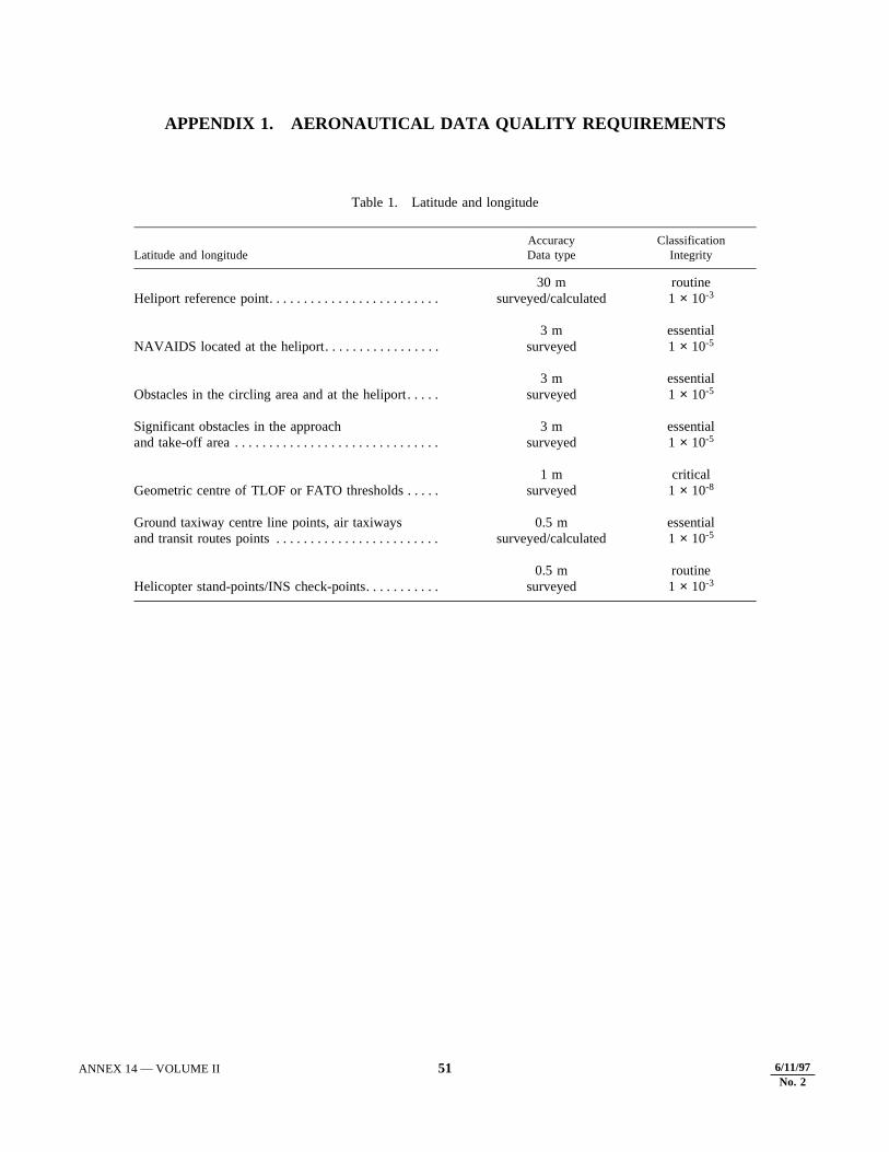
APPENDIX 1. AERONAUTICAL DATA QUALITY REQUIREMENTS
Table 1. Latitude and longitude
Latitude and longitudeAccuracyData type
ClassificationIntegrity
Heliport reference point. . . . . . . . . . . . . . . . . . . . . . . . . 30 m
surveyed/calculatedroutine1 × 10-3
NAVAIDS located at the heliport. . . . . . . . . . . . . . . . . 3 m
surveyedessential1 × 10-5
Obstacles in the circling area and at the heliport. . . . . 3 m
surveyedessential1 × 10-5
Significant obstacles in the approach and take-off area . . . . . . . . . . . . . . . . . . . . . . . . . . . . . .
3 msurveyed
essential1 × 10-5
Geometric centre of TLOF or FATO thresholds . . . . . 1 m
surveyedcritical1 × 10-8
Ground taxiway centre line points, air taxiways and transit routes points . . . . . . . . . . . . . . . . . . . . . . . .
0.5 msurveyed/calculated
essential1 × 10-5
Helicopter stand-points/INS check-points. . . . . . . . . . . 0.5 m
surveyedroutine1 × 10-3
ANNEX 14 — VOLUME II 51 9/11/95ANNEX 14 — VOLUME II 51 9/11/956/11/97No. 2

Annex 14 — Aerodromes Volume II
Table 2. Elevation/Altitude/Height
Table 3. Declination and magnetic variation
Elevation/altitude/heightAccuracyData type
ClassificationIntegrity
Heliport elevation . . . . . . . . . . . . . . . . . . . . . . . . . . . . . 0.5 m or 1 ftsurveyed
essential1 × 10-5
WGS-84 geoid undulation at heliport elevation position. . . . . . . . . . . . . . . . . . . . . . . . . . . . . .
0.5 m or 1 ftsurveyed
essential1 × 10-5
FATO threshold, non-precision approaches . . . . . . . . . 0.5 m or 1 ftsurveyed
essential1 × 10-5
WGS-84 geoid undulation at FATO threshold, TLOF geometric centre, non-precision approaches . . . . . . . . .
0.5 m or 1 ftsurveyed
essential1 × 10-5
FATO threshold, precision approaches. . . . . . . . . . . . . 0.25 m or 1 ftsurveyed
critical1 × 10-8
WGS-84 geoid undulation at FATO threshold, TLOF geometric centre, precision approaches . . . . . . .
0.25 m or 1 ftsurveyed
critical1 × 10-8
Obstacles in the approach and take-off areas . . . . . . . . 1 m or 1 ftsurveyed
essential1 × 10-5
Obstacles in the circling areas and at the heliport . . . . 1 m or 1 ftsurveyed
essential1 × 10-5
Distance measuring equipment/precision (DME/P) . . . 3 m (10 ft)surveyed
essential1 × 10-5
Declination/variationAccuracyData type
ClassificationIntegrity
Heliport magnetic variation. . . . . . . . . . . . . . . . . . . . . . 1 degreesurveyed
essential1 × 10-5
ILS localizer antenna magnetic variation . . . . . . . . . . . 1 degreesurveyed
essential1 × 10-5
MLS azimuth antenna magnetic variation . . . . . . . . . . 1 degreesurveyed
essential1 × 10-5
9/11/95 526/11/97No. 2

Appendix Annex 14 — Aerodromes
Table 4. Bearing
Table 5. Length/distance/dimension
— END —
BearingAccuracyData type
ClassificationIntegrity
ILS localizer alignment . . . . . . . . . . . . . . . . . . . . . . . . . 1/100 degree
surveyedessential1 × 10-5
MLS zero azimuth alignment . . . . . . . . . . . . . . . . . . . . 1/100 degree
surveyedessential1 × 10-5
FATO bearing . . . . . . . . . . . . . . . . . . . . . . . . . . . . . . . . 1/100 degree
surveyedroutine1 × 10-3
Length/distance/dimensionAccuracyData type
ClassificationIntegrity
FATO length, TLOF dimensions . . . . . . . . . . . . . . . . . 1 m or 1 ftsurveyed
critical1 × 10-8
Landing distance available . . . . . . . . . . . . . . . . . . . . . . 1 m or 1 ftsurveyed
critical1 × 10-8
ILS localizer antenna-FATO end, distance. . . . . . . . . . 3 m (10 ft)calculated
routine1 × 10-3
ILS glide slope antenna-threshold, distance along centre line . . . . . . . . . . . . . . . . . . . . . . .
3 m (10 ft)calculated
routine1 × 10-3
ILS markers-threshold distance. . . . . . . . . . . . . . . . . . . 3 m (10 ft)calculated
essential1 × 10-5
ILS DME antenna-threshold, distance along centre line . . . . . . . . . . . . . . . . . . . . . . .
3 m (10 ft)calculated
essential1 × 10-5
MLS azimuth antenna-FATO end, distance . . . . . . . . . 3 m (10 ft)calculated
routine1 × 10-3
MLS elevation antenna-threshold, distance along centre line . . . . . . . . . . . . . . . . . . . . . . .
3 m (10 ft)calculated
routine1 × 10-3
MLS DME/P antenna-threshold, distance along centre line . . . . . . . . . . . . . . . . . . . . . . .
3 m (10 ft)calculated
essential1 × 10-5
53 9/11/956/11/97No. 2