Advances in DWDM Transmission Technologies · PDF file1 | Infinera Confidential & Proprietary...
52
1 | Infinera Confidential & Proprietary Advances in DWDM Transmission Technologies Geoff Bennett: Director, Solutions and Technology Vinay Rathore: Snr. Director of Product Marketing
Transcript of Advances in DWDM Transmission Technologies · PDF file1 | Infinera Confidential & Proprietary...

1 | Infinera Confidential & Proprietary
Advances in DWDM Transmission Technologies Geoff Bennett: Director, Solutions and Technology
Vinay Rathore: Snr. Director of Product Marketing
2 | Infinera Confidential & Proprietary
Some Background • Spectral efficiency
• The impact of fiber impairments as modulation rate increases
The elements of a modern transmission system: • Phase modulation
• Polarization multiplexing
• Coherent detection
• Advanced digital signal processing
The next steps in high speed transmission • Higher order modulation: 8QAM, 16QAM
• Nyquist DWDM technologies for the transmitter
• Flexible Grid DWDM
• “Faster than Nyquist” technologies
Agenda

3 | Infinera Confidential & Proprietary
Some Background • Spectral efficiency
• The impact of fiber impairments as modulation rate increases
The elements of a modern transmission system: • Phase modulation
• Polarization multiplexing
• Coherent detection
• Advanced digital signal processing
The next steps in high speed transmission • Higher order modulation: 8QAM, 16QAM
• Nyquist DWDM technologies for the transmitter
• Flexible Grid DWDM
• “Faster than Nyquist” technologies
Agenda

4 | Infinera Confidential & Proprietary
Total fiber capacity is a function of: • Data rate per wavelength
• Number of wavelengths in the fiber
Capacity and Reach are antagonistic • If you increase one, you tend to decrease the other
But the general trend of DWDM innovation is to increase the product of Capacity and Reach*
DWDM Capacity Scaling Technologies
*Emmanuel B. Desurvire. “Capacity Demand and Technology Challenges for Lightwave Systems in the Next Two Decades” JOURNAL OF LIGHTWAVE TECHNOLOGY, VOL. 24, NO. 12, DECEMBER 2006

5 | Infinera Confidential & Proprietary
A History of DWDM Capacity x Distance Innovations
Emmanuel B. Desurvire. “Capacity Demand and Technology Challenges for Lightwave Systems in the Next Two Decades” JOURNAL OF LIGHTWAVE TECHNOLOGY, VOL. 24, NO. 12, DECEMBER 2006
Laser technology evolves to fiber
“sweet spot”

6 | Infinera Confidential & Proprietary
A History of DWDM Capacity x Distance Innovations
Emmanuel B. Desurvire. “Capacity Demand and Technology Challenges for Lightwave Systems in the Next Two Decades” JOURNAL OF LIGHTWAVE TECHNOLOGY, VOL. 24, NO. 12, DECEMBER 2006
Laser technology evolves to fiber
“sweet spot”
EDFA innovation enables WDM – multiple waves
in a fiber
7 | Infinera Confidential & Proprietary
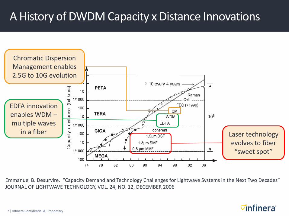
A History of DWDM Capacity x Distance Innovations
Emmanuel B. Desurvire. “Capacity Demand and Technology Challenges for Lightwave Systems in the Next Two Decades” JOURNAL OF LIGHTWAVE TECHNOLOGY, VOL. 24, NO. 12, DECEMBER 2006
Laser technology evolves to fiber
“sweet spot”
EDFA innovation enables WDM – multiple waves
in a fiber
Chromatic Dispersion Management enables 2.5G to 10G evolution

8 | Infinera Confidential & Proprietary
A History of DWDM Capacity x Distance Innovations
Emmanuel B. Desurvire. “Capacity Demand and Technology Challenges for Lightwave Systems in the Next Two Decades” JOURNAL OF LIGHTWAVE TECHNOLOGY, VOL. 24, NO. 12, DECEMBER 2006
Laser technology evolves to fiber
“sweet spot”
EDFA innovation enables WDM – multiple waves
in a fiber
Chromatic Dispersion Management enables 2.5G to 10G evolution Forward Error
Correction directly increases Cap*Reach

9 | Infinera Confidential & Proprietary
A History of DWDM Capacity x Distance Innovations
Emmanuel B. Desurvire. “Capacity Demand and Technology Challenges for Lightwave Systems in the Next Two Decades” JOURNAL OF LIGHTWAVE TECHNOLOGY, VOL. 24, NO. 12, DECEMBER 2006
Laser technology evolves to fiber
“sweet spot”
EDFA innovation enables WDM – multiple waves
in a fiber
Chromatic Dispersion Management enables 2.5G to 10G evolution Forward Error
Correction directly increases Cap*Dist
Addition of L-Band could double fiber capacity*

10 | Infinera Confidential & Proprietary
A History of DWDM Capacity x Distance Innovations
Emmanuel B. Desurvire. “Capacity Demand and Technology Challenges for Lightwave Systems in the Next Two Decades” JOURNAL OF LIGHTWAVE TECHNOLOGY, VOL. 24, NO. 12, DECEMBER 2006
Laser technology evolves to fiber
“sweet spot”
EDFA innovation enables WDM – multiple waves
in a fiber
Chromatic Dispersion Management enables 2.5G to 10G evolution Forward Error
Correction directly increases Cap*Dist
Addition of L-Band could double fiber capacity*
Raman amplification gives excellent distance boost

11 | Infinera Confidential & Proprietary
Large scale photonic integration • Makes the following technologies operationally scalable
Polarization muxing • Roughly 2x Capacity * Reach increase
Complex modulation • Increasing the “bits per symbol”
Coherent detection • Enables long haul transmission at 100Gb/s and beyond • Includes electronic CD and PMD compensation • >10x increase in Capacity * Reach
Soft Decision Forward Error Correction (SD-FEC) • Roughly 2x increase in Capacity * Reach vs HD-FEC
From fixed to flexible grid DWDM
Innovations that post-date this paper, but that are in production today

12 | Infinera Confidential & Proprietary
Super-channel: Multiple coherent carriers in a single line card, and brought into service at the same time
State of the Long Haul DWDM Market Today: Coherent, Flexible Grid Super-Channels
100G Line Card
100G Line Card
100G Line Card
100G Line Card
100G Line Card 500G Line Card
It’s practical to build (using PICs)…
Operationally scalable
The same or better optical performance as 100G

13 | Infinera Confidential & Proprietary
Laser
Continuous Wave
Laser Line Widths and Modulation Broadening
200GHz
100GHz
50GHz 25GHz
Telecom lasers have narrow line width

14 | Infinera Confidential & Proprietary
Laser
Continuous Wave
Laser Line Widths and Modulation Broadening
200GHz
100GHz
50GHz 25GHz
Telecom lasers have narrow line width
Modulating the carrier will broaden the width of the signal The faster you modulate, the broader the signal Modulator
0,1,1,1,0,0,0,0,1,1,0,1…
2.5Gb/s NRZ
10Gb/s NRZ
40Gb/s NRZ*
*This did not become a major implementation option

15 | Infinera Confidential & Proprietary
Why, at 40Gb/s and beyond, NRZ was not viable How long is a 1 or a 0?
2.5Gb/s 0.4 ns
The comparative duration of a symbol (bit)
0.1 ns 10Gb/s
0.025 ns 40Gb/s
0.001 ns 100Gb/s

16 | Infinera Confidential & Proprietary
Why, at 40Gb/s and beyond, NRZ was not viable How long is a 1 or a 0?
2.5Gb/s 0.4 ns
The comparative duration of a symbol
0.1 ns 10Gb/s
0.025 ns 40Gb/s
0.001 ns 100Gb/s
Why is this so significant?
Because impairments like CD and PMD become
“proportionately worse” as the symbol duration
decreases

17 | Infinera Confidential & Proprietary
Why, at 40Gb/s and beyond, NRZ was not viable How long is a 1 or a 0?
2.5Gb/s 0.4 ns
The comparative duration of a symbol
0.1 ns 10Gb/s
0.025 ns 40Gb/s
0.001 ns 100Gb/s
From 2.5G to 10G the industry had to learn to manage Chromatic Dispersion

18 | Infinera Confidential & Proprietary
Why, at 40Gb/s and beyond, NRZ was not viable How long is a 1 or a 0?
2.5Gb/s 0.4 ns
The comparative duration of a symbol
0.1 ns 10Gb/s
0.025 ns 40Gb/s
0.001 ns 100Gb/s
At this symbol rate for NRZ, PMD become unacceptable, and compensation is difficult
From 2.5G to 10G the industry had to learn to manage Chromatic Dispersion

19 | Infinera Confidential & Proprietary
Why, at 40Gb/s and beyond, NRZ was not viable How long is a 1 or a 0?
2.5Gb/s 0.4 ns
The comparative duration of a symbol
0.1 ns 10Gb/s
0.025 ns 40Gb/s
0.001 ns 100Gb/s
At this symbol rate for NRZ, PMD become unacceptable, and compensation is difficult
NRZ uses a direct detector, which operates on a square law, so Rx compensation is “challenging”
Can we use “smart” compensation technologies?
From 2.5G to 10G the industry had to learn to manage Chromatic Dispersion
We need to change to a different modulation technology

20 | Infinera Confidential & Proprietary
Some Background • Spectral efficiency
• The impact of fiber impairments as modulation rate increases
The elements of a modern transmission system: • Phase modulation
• Polarization multiplexing
• Coherent detection
• Advanced digital signal processing
The next steps in high speed transmission • Higher order modulation: 8QAM, 16QAM
• Nyquist DWDM technologies for the transmitter
• Flexible Grid DWDM
• “Faster than Nyquist” technologies
Agenda

21 | Infinera Confidential & Proprietary
Triple benefits of phase modulation…
Phase Modulation
Uses amplitude and phase to encode data, and is generally more tolerant of fiber impairments
We can use a coherent detector, which is linear, and thus allows us to compensate for linear
impairments in the receiver
We can use higher orders of phase modulation to encode more bits per symbol

22 | Infinera Confidential & Proprietary
Pol-Mux QPSK Modulation (Shows a single polarization here)
Im{Ex}
Re{Ex}
S1
This structure called a “Super Mach Zehnder”
S2
LD
Quadrature Phase Shift Keying
Q
I
90
Symbol constellation

23 | Infinera Confidential & Proprietary
QPSK Encodes 2 Bits Per Symbol
Q
I
Symbol constellation
Q
I
Q
I
Q
I
Q
I
01
11 10
00
24 | Infinera Confidential & Proprietary
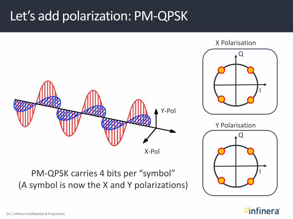
Let’s add polarization: PM-QPSK
Q
I
X-Pol
Y-Pol
Q
I
X Polarisation
Y Polarisation
PM-QPSK carries 4 bits per “symbol” (A symbol is now the X and Y polarizations)
25 | Infinera Confidential & Proprietary
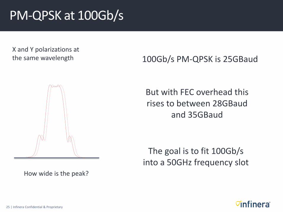
PM-QPSK at 100Gb/s
X and Y polarizations at the same wavelength 100Gb/s PM-QPSK is 25GBaud
But with FEC overhead this rises to between 28GBaud
and 35GBaud
How wide is the peak?
The goal is to fit 100Gb/s into a 50GHz frequency slot

26 | Infinera Confidential & Proprietary
Coherent Detectors
Use local oscillator • Highly discriminating receiver
• Low noise amplification
• Linear response

27 | Infinera Confidential & Proprietary
Coherent Detector In More Detail (For one wavelength only)
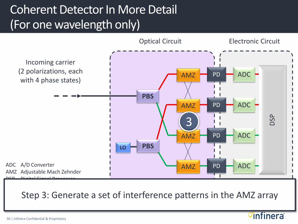
Incoming carrier (2 polarizations, each with 4 phase states)
ADC A/D Converter AMZ Adjustable Mach Zehnder DSP Digital Signal Processor LO Local Oscillator PD Photo Detector PBS Polarization Beam Splitter
LO
PD
PD
PD
PD
ADC
ADC
ADC
ADC
DSP
AMZ
AMZ
AMZ
AMZ
Optical Circuit Electronic Circuit
PBS
PBS

28 | Infinera Confidential & Proprietary
Incoming carrier (2 polarizations, each with 4 phase states)
LO
PD
PD
PD
PD
ADC
ADC
ADC
ADC
DSP
AMZ
AMZ
AMZ
AMZ
Optical Circuit Electronic Circuit
PBS
PBS
ADC A/D Converter AMZ Adjustable Mach Zehnder DSP Digital Signal Processor LO Local Oscillator PD Photo Detector PS Polarization Splitter
1
Step 1: Separate the X and Y polarizations
Coherent Detector In More Detail (For one wavelength only)

29 | Infinera Confidential & Proprietary
Incoming carrier (2 polarizations, each with 4 phase states)
LO
PD
PD
PD
PD
ADC
ADC
ADC
ADC
DSP
AMZ
AMZ
AMZ
AMZ
Optical Circuit Electronic Circuit
PBS
PBS
ADC A/D Converter AMZ Adjustable Mach Zehnder DSP Digital Signal Processor LO Local Oscillator PD Photo Detector PS Polarization Splitter
2
Step 2: Mix the two optical sources – signal and local oscillator
Coherent Detector In More Detail (For one wavelength only)
30 | Infinera Confidential & Proprietary
Incoming carrier (2 polarizations, each with 4 phase states)
LO
PD
PD
PD
PD
ADC
ADC
ADC
ADC
DSP
AMZ
AMZ
AMZ
AMZ
Optical Circuit Electronic Circuit
PBS
PBS
ADC A/D Converter AMZ Adjustable Mach Zehnder DSP Digital Signal Processor LO Local Oscillator PD Photo Detector PS Polarization Splitter
3
Step 3: Generate a set of interference patterns in the AMZ array
Coherent Detector In More Detail (For one wavelength only)

31 | Infinera Confidential & Proprietary
Incoming carrier (2 polarizations, each with 4 phase states)
LO
PD
PD
PD
PD
ADC
ADC
ADC
ADC
DSP
AMZ
AMZ
AMZ
AMZ
Optical Circuit Electronic Circuit
PBS
PBS
ADC A/D Converter AMZ Adjustable Mach Zehnder DSP Digital Signal Processor LO Local Oscillator PD Photo Detector PS Polarization Splitter
4
Step 4: Convert optical signals to analog electronic signals
Coherent Detector In More Detail (For one wavelength only)

32 | Infinera Confidential & Proprietary
Incoming carrier (2 polarizations, each with 4 phase states)
LO
PD
PD
PD
PD
ADC
ADC
ADC
ADC
DSP
AMZ
AMZ
AMZ
AMZ
Optical Circuit Electronic Circuit
PBS
PBS
ADC A/D Converter AMZ Adjustable Mach Zehnder DSP Digital Signal Processor LO Local Oscillator PD Photo Detector PS Polarization Splitter
5
Step 5: Convert analog to digital and process
Coherent Detector In More Detail (For one wavelength only)

33 | Infinera Confidential & Proprietary
The Impact of Coherent Detection and Sophisticated Signal Processing
Chromatic dispersion is bad!
PMD is even worse!
Data rates limited to 10Gb/s
Distances limited to about 2,500km
We may need to install new types of fiber to scale capacity
Before After

34 | Infinera Confidential & Proprietary
The Impact of Coherent Detection and Sophisticated Signal Processing
Chromatic dispersion is bad!
PMD is even worse!
Data rates limited to 10Gb/s
Distances limited to about 2,500km
We may need to install new types of fiber to scale capacity
We love chromatic dispersion!
PMD…no problem!
Data rates of 100Gb/s or more per carrier
Transmissions distances of:
• 4,500km (QPSK)
• 10,000km (BPSK)
The older the fiber, the better! (sort of)
Before After

35 | Infinera Confidential & Proprietary
Some Background • Spectral efficiency
• The impact of fiber impairments as modulation rate increases
The elements of a modern transmission system: • Phase modulation
• Polarization multiplexing
• Coherent detection
• Advanced digital signal processing
The next steps in high speed transmission • Higher order modulation: 8QAM, 16QAM
• Nyquist DWDM technologies for the transmitter
• Flexible Grid DWDM
• “Faster than Nyquist” technologies
Agenda
36 | Infinera Confidential & Proprietary
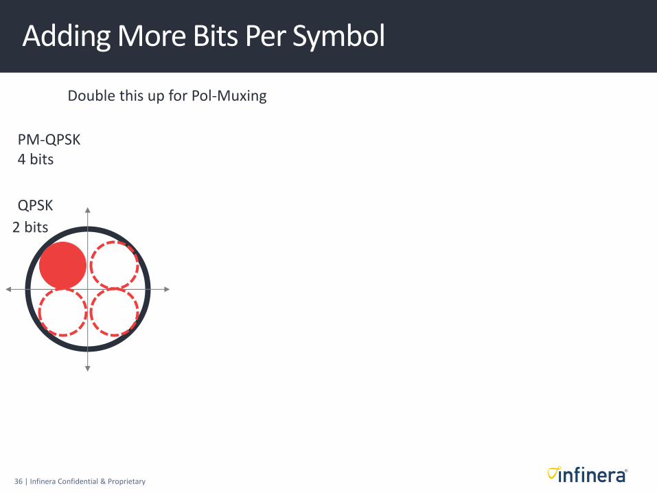
Adding More Bits Per Symbol
QPSK
2 bits
Double this up for Pol-Muxing
PM-QPSK 4 bits
37 | Infinera Confidential & Proprietary
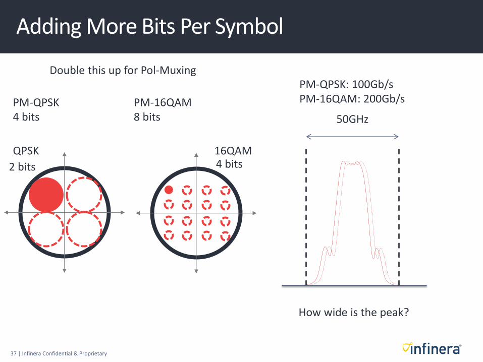
Adding More Bits Per Symbol
QPSK 16QAM
2 bits 4 bits
Double this up for Pol-Muxing
PM-QPSK 4 bits
PM-16QAM 8 bits
How wide is the peak?
50GHz
PM-QPSK: 100Gb/s PM-16QAM: 200Gb/s

38 | Infinera Confidential & Proprietary
Adding More Bits Per Symbol
QPSK 16QAM
2 bits 4 bits
Double this up for Pol-Muxing
PM-QPSK 4 bits
PM-16QAM 8 bits
Modulation order
PM BPSK
PM QPSK
PM 8QAM
PM 16QAM
C-B
and
Cap
acity (Tb/s)
5
10
15
20
Typ
ical
Rea
ch (
,00
0 k
m)
5
10
Reach drops dramatically using higher order modulation
39 | Infinera Confidential & Proprietary
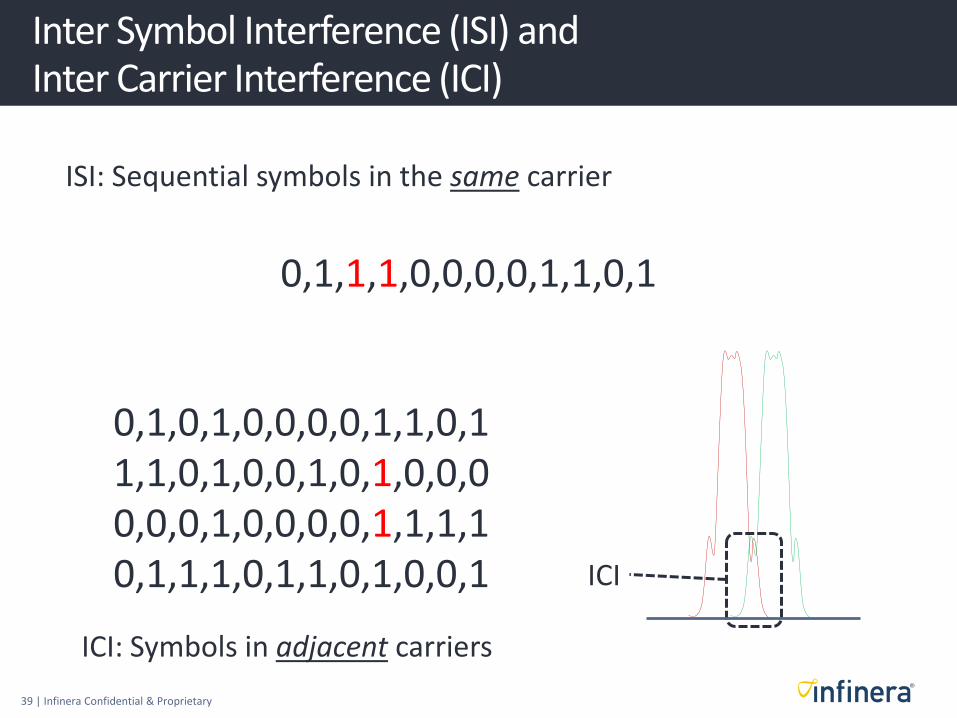
Inter Symbol Interference (ISI) and Inter Carrier Interference (ICI)
0,1,1,1,0,0,0,0,1,1,0,1
ISI: Sequential symbols in the same carrier
0,1,0,1,0,0,0,0,1,1,0,1 1,1,0,1,0,0,1,0,1,0,0,0 0,0,0,1,0,0,0,0,1,1,1,1 0,1,1,1,0,1,1,0,1,0,0,1
ICI: Symbols in adjacent carriers
ICI

40 | Infinera Confidential & Proprietary
Evolving Transmitter Technology (Note: Showing one polarization for simplicity)
S1
S2
LD
90
Today: 100Gb/s PM-QPSK
28-35GBaud symbol rate
4,500km reach

41 | Infinera Confidential & Proprietary
Evolving Transmitter Technology (Note: Showing one polarization for simplicity)
S1
S2
LD
90
Today: 100Gb/s PM-QPSK
28-35GBaud symbol rate
4,500km reach
Soon: 200Gb/s PM-16QAM
28-35GBaud symbol rate
700km reach
DAC
DSP
42 | Infinera Confidential & Proprietary
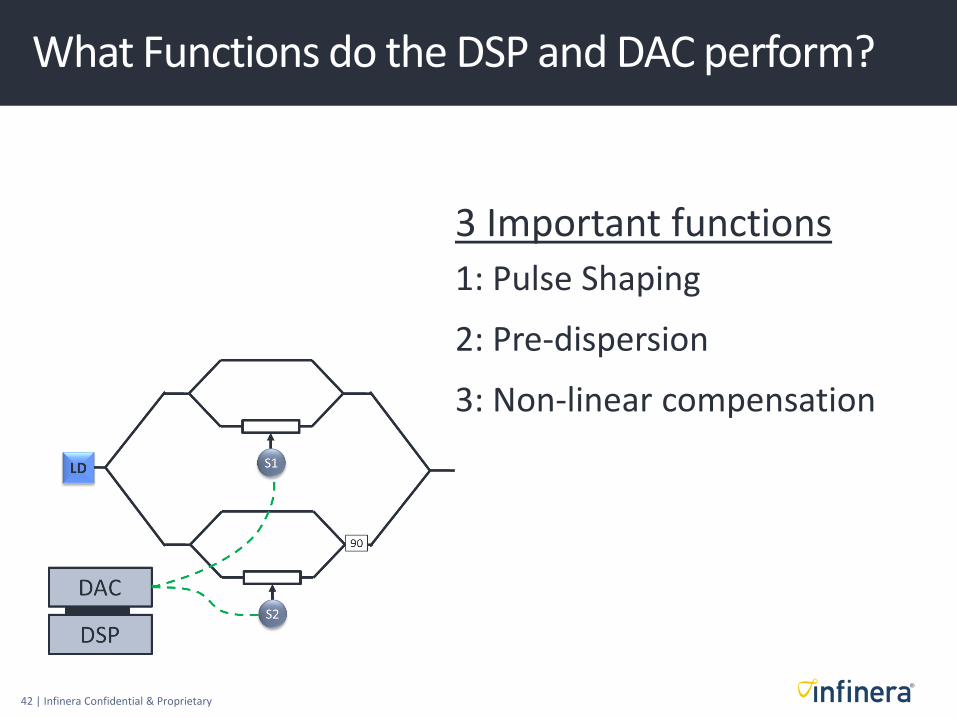
What Functions do the DSP and DAC perform?
3 Important functions
1: Pulse Shaping
2: Pre-dispersion
3: Non-linear compensation

43 | Infinera Confidential & Proprietary
ICI
Without DSP and DAC
Signal from the side lobes has been intelligently incorporated
into the main pulse
1: Intelligent Pulse Shaping

44 | Infinera Confidential & Proprietary
2: Pre-dispersion
Tx Rx
1 or 0? We know a signal will be dispersed as it travels along the fiber

45 | Infinera Confidential & Proprietary
2: Pre-dispersion
Tx Rx
1 or 0?
Using DSP and DAC we can apply negative direction of dispersion
before transmission

46 | Infinera Confidential & Proprietary
Promising demonstrations of NL Compensation gains of about 2dB OSNR improvements
An array of complex techniques: • NPCC: Nonlinear Polarization Crosstalk Correction
• AFCPR: Adaptive Fee-Forward Carrier Phase Recovery
• RF Pilot waves
• DBP: Digital Back Propagation
• Tx Pulse Pre-dispersion (aka pre-compensation, pre-emphasis)
3: Non-Linear Compensation
In general some techniques are promising for practical implementation over the next few years

47 | Infinera Confidential & Proprietary
Pulse-Shaped QPSK Spectrum
Using a DAC, driven by a DSP in the transmitter it’s possible to “shape” the pulse intelligently
Pulses can be spaced “at the Baud rate”
• Example: 28GBaud signal could be spaced at just over 28GHz
• The additional spacing is known as the alpha, and the practical limit for alpha is 3-4%
50GHz
Terminology: “Nyquist DWDM”
Laser Mod
DSP DAC
Transmitter
Alpha

48 | Infinera Confidential & Proprietary
FTN uses channel spacing < Baud rate
• One approach is tight optical filtering
• DSP and DAC in Tx also demonstrated
• Creates a major ISI penalty (between symbols in the same channels, caused by insufficient B/W)
• Also creates an ACI penalty (between adjacent channels) to a lesser degree
Techniques used to recover ISI penalty
• Example: Partial Response Signaling (eg. Quadrature Duobinary, QDB) – dates back to 1970s in radio
• But the tighter the filtering, the higher the penalty
MLSE* can be used to partly recover ISI penalty
• *Maximum Likelihood Sequence Estimation
Ultimately not as efficient as Nyquist DWDM using high order modulation
50GHz
Terminology: “Faster Than Nyquist DWDM”
Optical filtering of pulses

49 | Infinera Confidential & Proprietary
From Fixed to Flexible Grid
200GHz
100GHz
50GHz 25GHz
10Gb/s NRZ
100Gb/s PM-QPSK
In a fixed grid world we choose a grid spacing (eg. 50GHz) and then engineer the pulses to fit We might even force them to fit by taking a hit on the optical reach, or the fiber capacity
Pulse shaped signals may end up with “wasted spectrum” between neighboring fixed channels

50 | Infinera Confidential & Proprietary
Flexible slots have a total width granularity of 12.5GHz, but a center frequency granularity of 6.25GHz
The flexible slot is defined by two numbers, n and m • There’s a reference frequency of 193.1THz, and all flexible slots are defined
with respect to this reference frequency (outlined in red)
• The center of a given flexible slot is n x 6.25GHz from the reference frequency, and is m x 12.5GHz total width
ITU-T G.694.1 Flexible Grid

51 | Infinera Confidential & Proprietary
Over the past 5 years we have seen a major adoption of coherent technologies in long haul optical networks • These have delivered C-Band capacity in the 9.5Tb/s range, with reach of around 4,500km
using fixed ITU grids
There will continue to be a tradeoff of reach vs fiber capacity as we move to flexible grid • PM-QPSK capacity is up to 12Tb/s and reach of 4,500km
• PM-16QAM capacity is up to 24Tb/s, but with reach of only 700km
• “Intermediate” modulations such as 8QAM deliver a good compromise
Going beyond QPSK will require advances in Tx compensation technologies – some of which are not yet at the commercial stage
Interim solutions, such as FTN, probably will not be as effective as a true high order modulation approach
If we look even further we can see (almost) another doubling of fiber capacity enabled by L-Band operation • Some operational challenges to iron out!
Summary

52 | Infinera Confidential & Proprietary
Thank You!
Q&A