Addendum 2 for CABBlowerPrequal - draft - Regional … · ASME PTC-10 Performance Test Code on...
47
Addendum No. 2 to Request for Equipment Supplier Prequalification Channel Aeration High Speed Gearless Turbo Blowers For ECHOWATER PROJECT CHANNEL AERATION BLOWER REPLACEMENT (CAB) PROJECT RECEIPT OF THIS ADDENDUM MUST BE ACKNOWLEDGED IN THE SPACE PROVIDED ON THE REQUEST FOR PROPOSAL SUBMITTAL FORM February 7, 2018 Addendum No. 2 is hereby made part of the Regional San Request for Request for Equipment Supplier Prequalification Channel Aeration High Speed Gearless Turbo Blowers Dated January 25, 2018.
Transcript of Addendum 2 for CABBlowerPrequal - draft - Regional … · ASME PTC-10 Performance Test Code on...

Addendum No. 2
to
Request for Equipment Supplier Prequalification Channel Aeration
High Speed Gearless Turbo Blowers
For
ECHOWATER PROJECT CHANNEL AERATION BLOWER REPLACEMENT (CAB) PROJECT
RECEIPT OF THIS ADDENDUM MUST BE ACKNOWLEDGED IN THE SPACE PROVIDED ON THE REQUEST FOR PROPOSAL SUBMITTAL FORM
February 7, 2018
Addendum No. 2 is hereby made part of the Regional San Request for Request for Equipment Supplier Prequalification Channel Aeration High Speed Gearless Turbo Blowers Dated January 25, 2018.
EchoWater Project
CAB Request for Equipment Supplier Prequalification Channel Aeration High Speed Gearless Turbo Blowers 1
Addendum No. 2
to the Request for Equipment Supplier Prequalification
Channel Aeration High Speed Gearless Turbo Blowers
February 7, 2018
Bold indicates added or revised text and strikethroughs indicate deleted text.
Addendum
Item
Section and Page or
Drawing No. Location and Description of Change
2.001 Appendix C –
Specification 43 11 15
Replace Specification Section 43 11 15 in its entirety with
Specification Section 43 11 15 attached to this addendum.
Appendix C - 92X-101 -
P&ID EAST CHANNEL
AERATION BLOWER 1
Replace Drawing 92X-101 in its entirety with Drawing 92X-101
attached to this addendum.
2.002 Appendix C - 92X-102 -
P&ID EAST CHANNEL
AERATION BLOWER 2
Replace Drawing 92X-102 in its entirety with Drawing 92X-102
attached to this addendum.
2.003 Appendix C - 92X-103 -
P&ID EAST CHANNEL
AERATION BLOWER 3
Replace Drawing 92X-103 in its entirety with Drawing 92X-103
attached to this addendum.
2.004 Appendix C - 51X-101 –
P&ID WEST CHANNEL
AERATION BLOWER 1
Replace Drawing 51X-101 in its entirety with Drawing 51X-101
attached to this addendum.
2.005 Appendix C - 51X-102 -
P&ID WEST CHANNEL
AERATION BLOWER 2
Replace Drawing 51X-102 in its entirety with Drawing 51X-102
attached to this addendum.
2.006 Appendix C - 51X-103 -
P&ID WEST CHANNEL
AERATION BLOWER 3
Replace Drawing 51X-103 in its entirety with Drawing 51X-103
attached to this addendum.
2.007 Appendix C - 51X-104 -
P&ID WEST CHANNEL
AERATION BLOWER 4
Replace Drawing 51X-104in its entirety with Drawing 51X-104
attached to this addendum.
Addendum No. 2 is hereby made part of the Regional San Request for Request for Equipment Supplier Prequalification Channel Aeration High Speed Gearless Turbo Blowers Dated January 25, 2018.
END OF ADDENDUM
3/15/18 CAB Project 43 11 15 - 1
SECTION 43 11 15
HIGH SPEED GEARLESS TURBO BLOWERS
PART 1 - GENERAL
1.01 SCOPE
A. For the purpose of this section, the High Speed Gearless Turbo Blower manufacturer shall be referred to as the Supplier or manufacturer. The supplier shall provide equipment and services defined herein. The Contractor shall refer to the General Contractor and/or Subcontractor.
B. This section covers the furnishing and installation of electric motor driven, high speed, non-contact bearing type turbo blowers complete with sound enclosures and all accessories as indicated on the Drawings and as specified herein.
C. The Contractor shall provide the High Speed Gearless Turbo Blowers (Blowers) and accessories as specified herein.
1. Blower designation. East Aeration Blowers
West Aeration Blowers
2. Number of blowers. 3 4
3. Blower tag numbers. B921001 B921002 B921003
B517511 B517512 B517513 B517514
4. Blower location. Blower Mezzanine Blower Building
D. The blowers shall be air-cooled or liquid-cooled and complete with integral adjustable frequency drive, electric drive motor, base, acoustical enclosure, intake filter, integrated input harmonic filter, controls, spare parts, and all other accessories or appurtenances indicated on the Drawings, specified herein or otherwise needed for proper operation.
E. The Supplier shall provide each Blower with a Programmable Logic Controller (PLC) or Microcomputer for the purpose of controlling the Blower, supporting equipment, and accessories mounted external to each blower package including any required instrumentation and valve actuators necessary for the operation the individual Blower.
F. Piping, pipe supports, valves, and accessories that are not an integral part of the equipment as indicated on the Drawings or specified herein are covered in other sections.
3/15/18 CAB Project 43 11 15 - 2
G. The Supplier shall provide all programming, configuration, testing, and validation for each Blower PLC or Microcomputer.
H. The Supplier shall provide an Operator Interface Terminal (OIT) for local control, monitoring, and maintenance activities for each Blower. Prior to the start of configuration of the OIT the Supplier shall meet with the District and discuss the all configuration standard including but not limited to color conventions, screen layout, navigation, alarming, alarm acknowledgement and other standards.
I. The Supplier shall provide configuration and integration services including programming to operate all equipment provided as part of each Blower package and programming code to be implemented in Contractor provided Master Blower PLC referred to as Area PLC. Refer to paragraph 3.07 for additional requirements.
J. Each Turbo Blower shall be provided with an Ethernet Switch that will be integrated into a broader plant wide network. All IP addresses used shall be coordinated with the District prior to Shop Testing and PLC and OIT configurations. The configuration of all Ethernet switches will require workshops prior to installing any Ethernet Equipment in the field. Refer to Part three of this specification for additional requirements.
1.02 GENERAL
A. COORDINATION. Equipment furnished under this section shall be fabricated and assembled in full conformity with drawings, specifications, engineering data, instructions, and recommendations furnished by the gearless turbo supplier, unless exceptions are noted by the District Representative.
1. Each blower unit shall be a current standard product of the blower manufacturer and
shall be a packaged type unit, fully shop assembled by the blower manufacturer. All accessory items shall be furnished by the gearless turbo supplier.
2. Each blower package, including the blower unit, control panel, any cooling air or
liquid requirements, harmonic filter, and adjustable frequency drive shall not exceed the limiting dimensions as specified herein. Any proposed modifications shall be reviewed by the District Representative and if accepted, shall be provided by Supplier at no additional cost to District.
3. Unless exceptions are noted by District Representative, the equipment arrangement
and piping may be modified in accordance with the recommendations of the equipment manufacturer to suit the equipment furnished. All needed modifications shall be reviewed by District Representative and shall be performed by Contractor at no additional cost to District.
B. METEOROLOGICAL AND SEISMIC DESIGN CRITERIA. The
METEOROLOGICAL AND SEISMIC DESIGN CRITERIA Section (01 87 14) shall apply to all equipment furnished under this section.

3/15/18 CAB Project 43 11 15 - 3
C. GOVERNING STANDARDS. Except as modified or supplemented herein, all work
covered by this section shall be performed in accordance with all applicable municipal codes and ordinances, laws, and regulations which pertain to such work. In case of a conflict between these specifications and any state law or local ordinance, the latter shall govern.
D. POWER SUPPLY. Unless otherwise indicated, power supply to the equipment will be
480 volts, 60 Hz, 3 phase.
E. TAGGING. Each item of equipment and each part shipped separately shall be tagged and identified with indelible markings for the intended service. Tag number shall be clearly marked on all shipping labels and on the outside of all containers.
F. NAMEPLATES. The blowers and accessory component having a tag number as
indicated on the Drawings or specified herein shall be provided with a permanent number plate as specified below:
1. Nameplates shall be provided on each item of equipment in accordance with EQUIPMENT IDENTIFICATION Section (01 68 00). Equipment nameplates shall be 16-gauge stainless steel bearing the equipment name and equipment number legibly engraved in ¾-inch high letters. Nameplates shall be attached to the equipment in an accessible location with stainless steel screws. .
G. LUBRICATION. The blowers shall not require oils or lubricants for adequate operation.
1.03 REFERENCES
A. REFERENCE STANDARDS: The publications referred to hereinafter form a part of this specification to the extent referenced. The publications are referred to in the text by the basic designation only. The latest edition of referenced publications in effect at the time of the bid shall govern. In case of conflict between the requirements of this section and the listed references, the requirements of this section shall prevail.
Reference Title
AISI American Iron and Steel Institute
ANSI B40.100 Pressure Gauges and Gauge Attachments ASME PTC-10 Performance Test Code on Compressors and Exhausters
ASME PTC-19.5 Flow Measurement
ASTM A36 Standard Specification for Carbon Structural Steel
ASTM A356 Standard Specification for Steel Castings, Carbon, Low Alloy, and Stainless Steel, Heavy Walled Steam Turbines
3/15/18 CAB Project 43 11 15 - 4
ASTM C547 Standard Specification for Mineral Fiber Pipe Insulation
DIN EN 12717 Safety of Machine Tools – Drilling Machines
IEEE 519 Recommended Practice and Requirements for Harmonic Control in Electric Power Systems
IEEE C57.110 Recommended Practice for Establishing Liquid-Filled and Dry-Type Power and Distribution Transformer Capacity When Supplying Nonsinusoidal Load Currents
ISO 1940 Mechanical Vibration – Balance Quality Requirements for Rotors
in a Constant (Rigid) State NEMA MG1 Motors and Generators NFPA 70 National Electrical Code
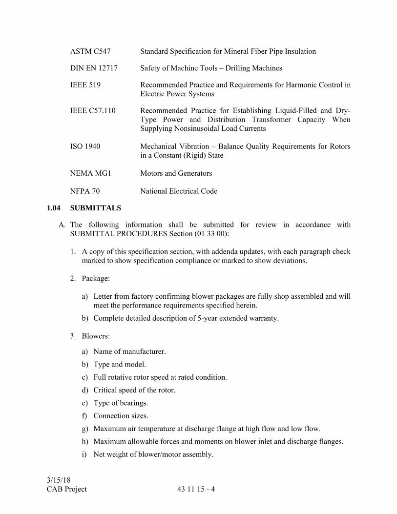
1.04 SUBMITTALS
A. The following information shall be submitted for review in accordance with SUBMITTAL PROCEDURES Section (01 33 00): 1. A copy of this specification section, with addenda updates, with each paragraph check
marked to show specification compliance or marked to show deviations.
2. Package: a) Letter from factory confirming blower packages are fully shop assembled and will
meet the performance requirements specified herein.
b) Complete detailed description of 5-year extended warranty.
3. Blowers:
a) Name of manufacturer.
b) Type and model.
c) Full rotative rotor speed at rated condition.
d) Critical speed of the rotor.
e) Type of bearings.
f) Connection sizes.
g) Maximum air temperature at discharge flange at high flow and low flow.
h) Maximum allowable forces and moments on blower inlet and discharge flanges.
i) Net weight of blower/motor assembly.
3/15/18 CAB Project 43 11 15 - 5
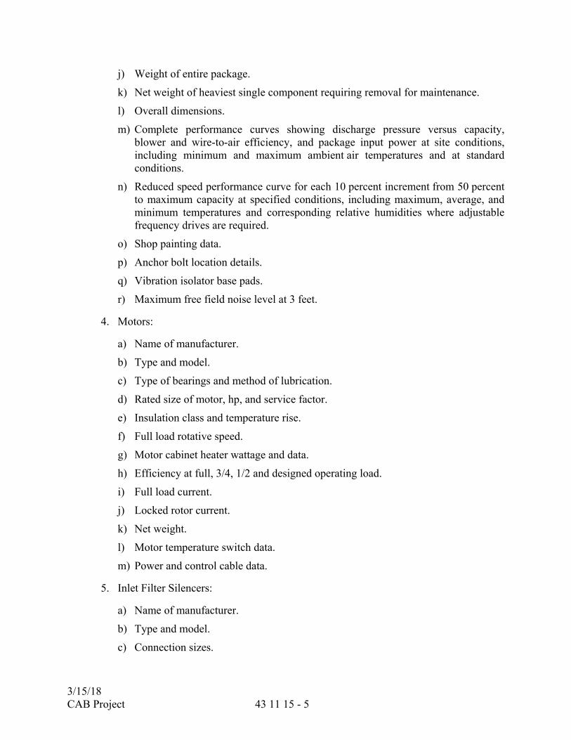
j) Weight of entire package.
k) Net weight of heaviest single component requiring removal for maintenance.
l) Overall dimensions.
m) Complete performance curves showing discharge pressure versus capacity, blower and wire-to-air efficiency, and package input power at site conditions, including minimum and maximum ambient air temperatures and at standard conditions.
n) Reduced speed performance curve for each 10 percent increment from 50 percent to maximum capacity at specified conditions, including maximum, average, and minimum temperatures and corresponding relative humidities where adjustable frequency drives are required.
o) Shop painting data.
p) Anchor bolt location details.
q) Vibration isolator base pads.
r) Maximum free field noise level at 3 feet.
4. Motors:
a) Name of manufacturer.
b) Type and model.
c) Type of bearings and method of lubrication.
d) Rated size of motor, hp, and service factor.
e) Insulation class and temperature rise.
f) Full load rotative speed.
g) Motor cabinet heater wattage and data.
h) Efficiency at full, 3/4, 1/2 and designed operating load.
i) Full load current.
j) Locked rotor current.
k) Net weight.
l) Motor temperature switch data.
m) Power and control cable data.
5. Inlet Filter Silencers:
a) Name of manufacturer.
b) Type and model.
c) Connection sizes.

3/15/18 CAB Project 43 11 15 - 6
d) Overall dimensions.
e) Shop painting data.
f) Materials of construction, including packing materials.
g) Initial pressure drop at rated air flow.
h) Sound attenuation at each octave band.
i) Filter particle arrestance and efficiency.
j) Filter material.
k) Weight of entire package.
6. Controls:
a) Blower control panel layout, including interior and exterior views including dimensions.
b) Accessory device data, including catalog cut sheets on all control components.
c) Bill of Materials.
d) Sequence of operations.
e) Wiring diagrams.
f) Information associated with the PLC as specified herein and in the PROGRAMMABLE LOGIC CONTROLLERS Section (40 63 43)
1) An electronic AutoCAD file and PDF file of PLC program. The PLC program shall be fully annotated. An explanation shall be provided for each rung, and every contact, coil, network and function block and shall be identified and its functionality fully described.
2) Programming documentation including Profibus and Ethernet networks for all field devices monitored and controlled by the vendor furnished PLC.
3) An I/O list that includes all the relevant parameters for each I/O point such as range, active state, contact orientation, limits, incremental limits. I/O card addresses and PLC assignment.
4) The I/O database shall include the District’s standard tag name in the alias field, The District standard tag names are shown on the P&IDs.
7. Instrumentation:
a) Manufacturer and model.
b) Catalog cuts of instrument data sheets.
c) Materials of construction.
d) Temperature rating.

3/15/18 CAB Project 43 11 15 - 7
e) Special requirements.
f) Operation and maintenance manuals.
g) Installation details.
8. Blowoff Silencers:
a) Dimensions and connection sizes and types.
b) Sound attenuation at each octave band.
c) Materials of construction, including packing materials.
d) Pressure drop at rated air flow.
9. Check Valve:
a) Manufacturer and model.
b) Dimensions.
c) Materials of construction.
d) Pressure drop at rated air flow.
10. Accessories:
a) Name of manufacturer.
b) Equipment data.
c) Drawings.
d) Wiring diagrams and schematics.
11. Certified Shop Test Reports:
a) Performance test plan, including arrangement drawing, instrument calibration certificates, and data collection sheets.
b) Performance curves.
c) Pressure gauge calibration procedure.
d) Rotor balancing report.
e) Test data.
f) Sample calculations showing correction of test conditions to contract conditions.
B. CONFIGURATION AND PROGRAMMING SUBMITTALS: 1. Kick-Off Meeting:
a) Agenda items required for the meeting
b) Documentation detailed of blower equipment features and functionality

3/15/18 CAB Project 43 11 15 - 8
2. Coordination Meeting:
a) Agenda items required for the meeting
b) Documentation of the meeting
3. Testing Procedures and Validations Forms
C. DRAWINGS AND DATA. Complete assembly and installation drawings, wiring and schematic diagrams, together with detailed specifications and data covering materials used, parts, devices and other accessories forming a part of the equipment furnished, shall be submitted in accordance with the SUBMITTALS PROCEDURES Section (01 33 00). Device tag numbers indicated on the contract drawings shall be referenced on the wiring and schematic diagrams where applicable. The data and specifications for the unit shall include, but not be limited to, the items listed in 1.03, Section A above.
1.05 OPERATION AND MAINTENANCE INSTRUCTIONS
A. Submit operation and maintenance (O&M) instructions in accordance with the OPERATION AND MAINTENANCE DATA Section (01 78 23) by submitting a copy of the OPERATION AND MAINTENANCE DATA Section (01 78 23) with each paragraph check marked to show compliance. O&M instructions shall be submitted after all submittals specified above have been returned mark “No Exceptions Taken” or “Make Corrections Noted”. O&M instructions shall reflect the approved materials and equipment.
1.06 DELIVERY, STORAGE, AND HANDLING
A. Each blower package shall be shipped with vibration mount that will indicate if the blower package received a potentially damaging, hard jar during shipping.
B. The blower packages shall be inspected upon arrival and need to be stored indoors in a dry area until time of installation. Long-term storage requirements of the blower manufacturers shall be followed until the blowers are to be installed.
C. Shipping and storage shall be in accordance with the PRODUCT DELIVERY REQUIREMENTS Section (01 65 00) or as herein. Contractor to coordinate with the Supplier regarding storage requirements.
1.07 SPARE PARTS
A. The manufacturer’s recommended spare parts and special tools lists shall be in accordance with the OPERATION AND MAINTENANCE DATA Section (01 78 23).
3/15/18 CAB Project 43 11 15 - 9
PART 2 - PRODUCTS
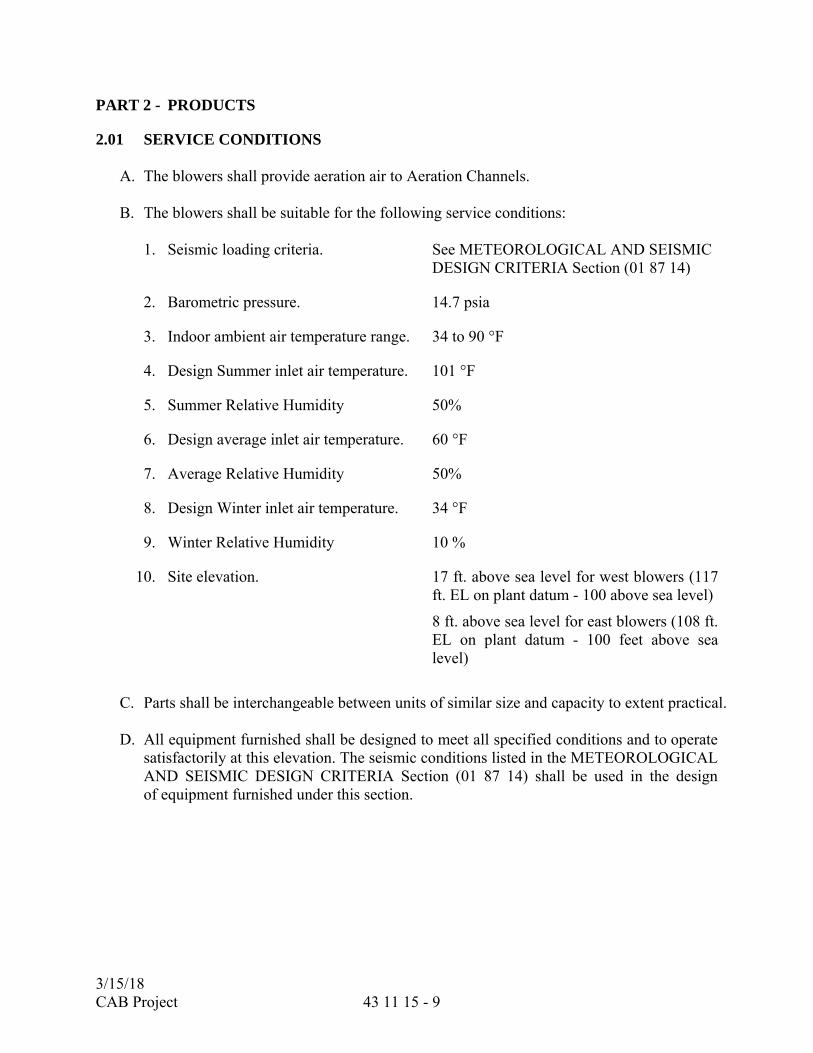
2.01 SERVICE CONDITIONS
A. The blowers shall provide aeration air to Aeration Channels.
B. The blowers shall be suitable for the following service conditions:
1. Seismic loading criteria. See METEOROLOGICAL AND SEISMIC DESIGN CRITERIA Section (01 87 14)
2. Barometric pressure. 14.7 psia
3. Indoor ambient air temperature range. 34 to 90 °F
4. Design Summer inlet air temperature. 101 °F
5. Summer Relative Humidity 50%
6. Design average inlet air temperature. 60 °F
7. Average Relative Humidity 50%
8. Design Winter inlet air temperature. 34 °F
9. Winter Relative Humidity 10 %
10. Site elevation. 17 ft. above sea level for west blowers (117 ft. EL on plant datum - 100 above sea level)
8 ft. above sea level for east blowers (108 ft. EL on plant datum - 100 feet above sea level)
C. Parts shall be interchangeable between units of similar size and capacity to extent practical.
D. All equipment furnished shall be designed to meet all specified conditions and to operate
satisfactorily at this elevation. The seismic conditions listed in the METEOROLOGICAL AND SEISMIC DESIGN CRITERIA Section (01 87 14) shall be used in the design of equipment furnished under this section.
3/15/18 CAB Project 43 11 15 - 10
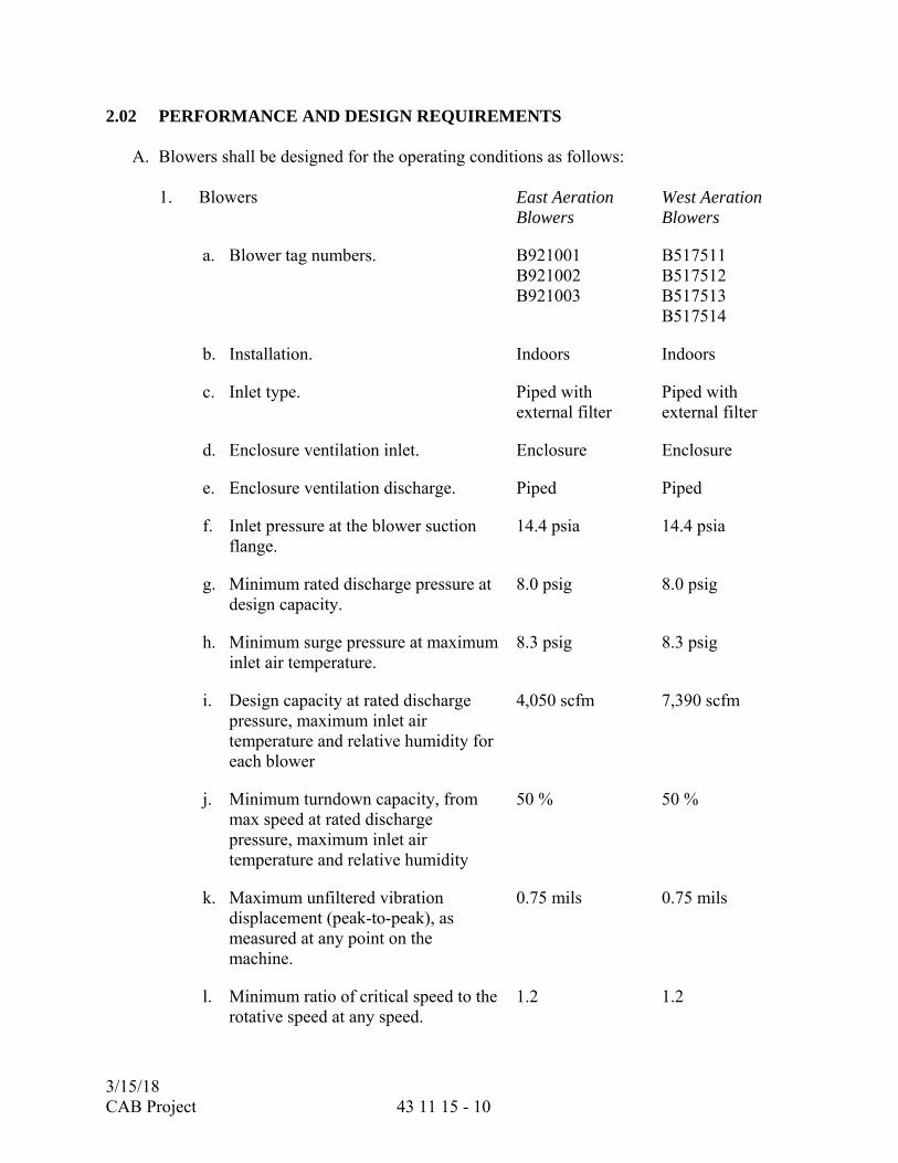
2.02 PERFORMANCE AND DESIGN REQUIREMENTS
A. Blowers shall be designed for the operating conditions as follows:
1. Blowers East Aeration Blowers
West Aeration Blowers
a. Blower tag numbers. B921001 B921002 B921003
B517511 B517512 B517513 B517514
b. Installation. Indoors Indoors
c. Inlet type. Piped with external filter
Piped with external filter
d. Enclosure ventilation inlet. Enclosure Enclosure
e. Enclosure ventilation discharge. Piped Piped
f. Inlet pressure at the blower suction flange.
14.4 psia 14.4 psia
g. Minimum rated discharge pressure at design capacity.
8.0 psig 8.0 psig
h. Minimum surge pressure at maximum inlet air temperature.
8.3 psig 8.3 psig
i. Design capacity at rated discharge pressure, maximum inlet air temperature and relative humidity for each blower
4,050 scfm 7,390 scfm
j. Minimum turndown capacity, from max speed at rated discharge pressure, maximum inlet air temperature and relative humidity
50 % 50 %
k. Maximum unfiltered vibration displacement (peak-to-peak), as measured at any point on the machine.
0.75 mils 0.75 mils
l. Minimum ratio of critical speed to the rotative speed at any speed.
1.2 1.2

3/15/18 CAB Project 43 11 15 - 11
m. Maximum guaranteed package wire-to-air power required at rated discharge pressure, design capacity, Summer inlet air temperature and relative humidity.
152.2 kW 277.7 kW
n. Maximum guaranteed package wire-to-air power required at rated discharge pressure, design capacity, Average inlet air temperature and relative humidity
136.4 kW 248.3 kW
o. Maximum guaranteed package wire-to-air power required at rated discharge pressure, design capacity, Winter inlet air temperature and relative humidity.
128.1 kW 232.2 kW
p. Maximum drive motor rating. 250 hp 400 hp
2. Maximum Acceptable Package Dimensions
a. Length. 85 in. 97 in.
b. Width. 55 in. 81 in.
c. Height to discharge flange. 90 in. 126 in.
3. Intake Filter
a. Equipment tag number. FLTA921001 FLTA921002 FLTA921003
FLTA517511 FLTA517512 FLTA517513 FLTA517514
b. Type. Inline Cartridge Cartridge
c. Minimum rated flow. 8,100 Inlet cfm 14,790 Inlet cfm
d. Maximum initial pressure drop. 2 in wc 2 in wc
e. Maximum face velocity. 50 ft/min 50 ft/min
f. Particle arrestance (removal percentage/size).
98 / 10 %/μm 98 / 10 %/μm
3/15/18 CAB Project 43 11 15 - 12
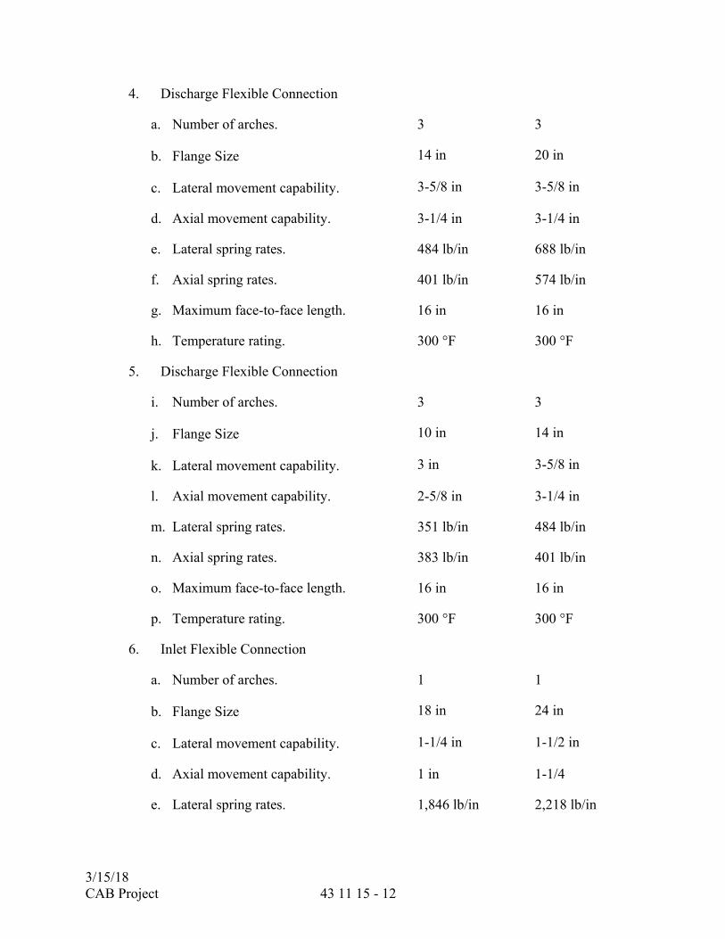
4. Discharge Flexible Connection
a. Number of arches. 3 3
b. Flange Size 14 in 20 in
c. Lateral movement capability. 3-5/8 in 3-5/8 in
d. Axial movement capability. 3-1/4 in 3-1/4 in
e. Lateral spring rates. 484 lb/in 688 lb/in
f. Axial spring rates. 401 lb/in 574 lb/in
g. Maximum face-to-face length. 16 in 16 in
h. Temperature rating. 300 °F 300 °F
5. Discharge Flexible Connection
i. Number of arches. 3 3
j. Flange Size 10 in 14 in
k. Lateral movement capability. 3 in 3-5/8 in
l. Axial movement capability. 2-5/8 in 3-1/4 in
m. Lateral spring rates. 351 lb/in 484 lb/in
n. Axial spring rates. 383 lb/in 401 lb/in
o. Maximum face-to-face length. 16 in 16 in
p. Temperature rating. 300 °F 300 °F
6. Inlet Flexible Connection
a. Number of arches. 1 1
b. Flange Size 18 in 24 in
c. Lateral movement capability. 1-1/4 in 1-1/2 in
d. Axial movement capability. 1 in 1-1/4
e. Lateral spring rates. 1,846 lb/in 2,218 lb/in

3/15/18 CAB Project 43 11 15 - 13
f. Axial spring rates. 1,548 lb/in 2,066 lb/in
g. Maximum face-to-face length. 8 in 10 in
h. Temperature rating. 300 °F 300 °F
Note: (1) Refer to Performance Test paragraph herein for more information. (2) Neuros to use engineering approved 3 arch, 12” expansion joint for east blowers. (3) If blower manufacturer has a smaller inlet or discharge on either east and or west blowers, they may use increasing a manufacturer provided, expansion joint in order to get to the appropriate size, the increasing expansion joint shall still be required to meet movement and spring rates specified.
B. Standard cubic feet per minute (scfm) is defined as air at 14.7 psia, 68°F and 36 percent relative humidity. Blowers shall be capable of providing the specified mass flow in scfm throughout the entire operating flow and ambient temperature range including at the specified summer conditions
C. Wire-to-air power shall be defined as specified herein.
D. The blower electronics including the adjustable frequency drive and the harmonic filter
shall be provided with a factory applied coating rated for 3C3 environment.
E. Blower performance curves shall be matched. Each performance curve shall be sloped so that the discharge pressure is continuously decreasing with increasing flow. Blowers shall be designed to be capable of coming on line against a fully pressurized discharge header. All necessary components for blowoff or unloading line, including piping, silencer, automatic valves, actuators and controls, shall be provided by the gearless turbo supplier at no additional cost to District.
*Measured power and guaranteed power shall be wire-to-air and shall include all losses associated with package electrical input power, including, but not limited to, the motor, inverter, harmonic filter, and cooling systems, if used. Harmonic filter and sinus filter losses shall be included even if the harmonic filter is mounted outside the blower package. Input wire-to-air power shall exclude any power used for air conditioning cabinet for the electrical compartment.

3/15/18 CAB Project 43 11 15 - 14
Performance Power Guarantee Table:
Design Point Capacity
Inlet Pressure
Drop Discharge Pressure
Design Conditions
Weighted Factor
Power Guarantee
West Blowers
scfm psi psig °F / %RH kW
Summer 7,390 0.3 8.0 101/50 0.10 277.7
Average 7,390 0.3 8.0 60/50 0.80 248.3
Winter 7,390 0.3 8.0 34/10 0.10 232.2
Total factored power draw (kW) 249.7
East Blowers
scfm psi psig °F / %RH kW
Summer 4,050 0.3 8.0 101/50 0.10 152.2
Average 4,050 0.3 8.0 60/50 0.80 136.4
Winter 4,050 0.3 8.0 34/10 0.10 128.1
Total factored power draw (kW) 137.2
2.03 ACCEPTABLE MANUFACTURERS
A. Acceptable manufacturers shall have a United States installation list showing installations which have been operating for a minimum of 6 years in at least 50 wastewater treatment plants. Blower packages certified by a Nationally Recognized Testing Laboratories. Any modifications to the layout required to accommodate any manufacturer shall be the responsibility of the Contractor and subject to acceptance by the District Representative. All costs of modifications shall be at no cost to the District.
2.04 MATERIALS
A. Flexible Joint Elastomeric, arched type.
B. Blowoff Silencer Steel, ASTM A36.
C. Blowoff Valve Steel body with manufacturer's standard internals.
3/15/18 CAB Project 43 11 15 - 15
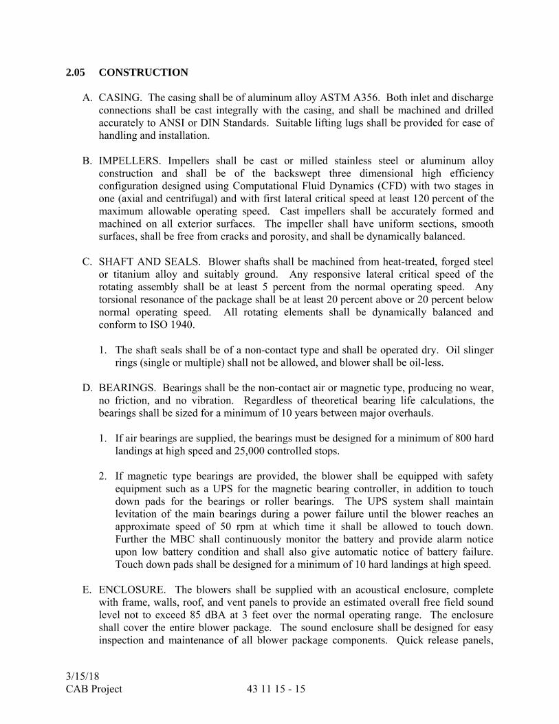
2.05 CONSTRUCTION
A. CASING. The casing shall be of aluminum alloy ASTM A356. Both inlet and discharge connections shall be cast integrally with the casing, and shall be machined and drilled accurately to ANSI or DIN Standards. Suitable lifting lugs shall be provided for ease of handling and installation.
B. IMPELLERS. Impellers shall be cast or milled stainless steel or aluminum alloy
construction and shall be of the backswept three dimensional high efficiency configuration designed using Computational Fluid Dynamics (CFD) with two stages in one (axial and centrifugal) and with first lateral critical speed at least 120 percent of the maximum allowable operating speed. Cast impellers shall be accurately formed and machined on all exterior surfaces. The impeller shall have uniform sections, smooth surfaces, shall be free from cracks and porosity, and shall be dynamically balanced.
C. SHAFT AND SEALS. Blower shafts shall be machined from heat-treated, forged steel
or titanium alloy and suitably ground. Any responsive lateral critical speed of the rotating assembly shall be at least 5 percent from the normal operating speed. Any torsional resonance of the package shall be at least 20 percent above or 20 percent below normal operating speed. All rotating elements shall be dynamically balanced and conform to ISO 1940. 1. The shaft seals shall be of a non-contact type and shall be operated dry. Oil slinger
rings (single or multiple) shall not be allowed, and blower shall be oil-less.
D. BEARINGS. Bearings shall be the non-contact air or magnetic type, producing no wear, no friction, and no vibration. Regardless of theoretical bearing life calculations, the bearings shall be sized for a minimum of 10 years between major overhauls.
1. If air bearings are supplied, the bearings must be designed for a minimum of 800 hard
landings at high speed and 25,000 controlled stops.
2. If magnetic type bearings are provided, the blower shall be equipped with safety equipment such as a UPS for the magnetic bearing controller, in addition to touch down pads for the bearings or roller bearings. The UPS system shall maintain levitation of the main bearings during a power failure until the blower reaches an approximate speed of 50 rpm at which time it shall be allowed to touch down. Further the MBC shall continuously monitor the battery and provide alarm notice upon low battery condition and shall also give automatic notice of battery failure. Touch down pads shall be designed for a minimum of 10 hard landings at high speed.
E. ENCLOSURE. The blowers shall be supplied with an acoustical enclosure, complete
with frame, walls, roof, and vent panels to provide an estimated overall free field sound level not to exceed 85 dBA at 3 feet over the normal operating range. The enclosure shall cover the entire blower package. The sound enclosure shall be designed for easy inspection and maintenance of all blower package components. Quick release panels,
3/15/18 CAB Project 43 11 15 - 16
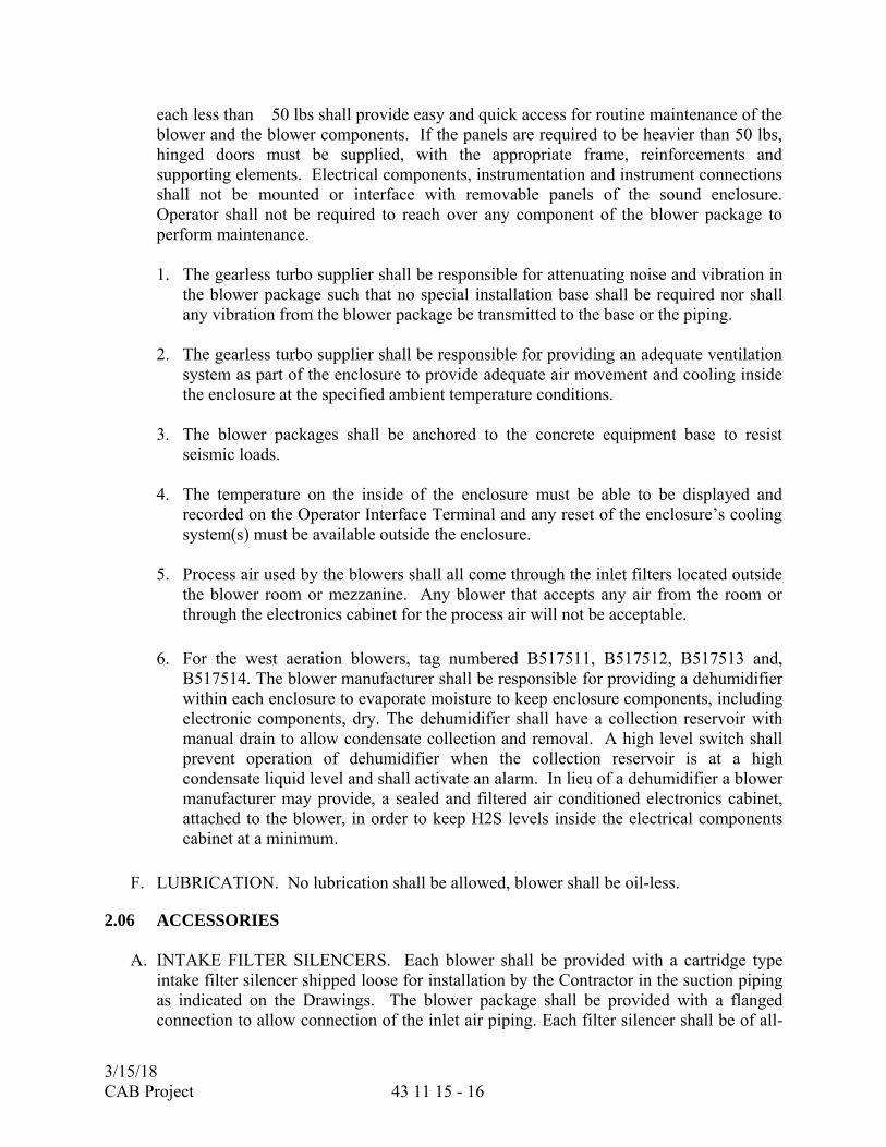
each less than 50 lbs shall provide easy and quick access for routine maintenance of the blower and the blower components. If the panels are required to be heavier than 50 lbs, hinged doors must be supplied, with the appropriate frame, reinforcements and supporting elements. Electrical components, instrumentation and instrument connections shall not be mounted or interface with removable panels of the sound enclosure. Operator shall not be required to reach over any component of the blower package to perform maintenance.
1. The gearless turbo supplier shall be responsible for attenuating noise and vibration in
the blower package such that no special installation base shall be required nor shall any vibration from the blower package be transmitted to the base or the piping.
2. The gearless turbo supplier shall be responsible for providing an adequate ventilation
system as part of the enclosure to provide adequate air movement and cooling inside the enclosure at the specified ambient temperature conditions.
3. The blower packages shall be anchored to the concrete equipment base to resist
seismic loads.
4. The temperature on the inside of the enclosure must be able to be displayed and recorded on the Operator Interface Terminal and any reset of the enclosure’s cooling system(s) must be available outside the enclosure.
5. Process air used by the blowers shall all come through the inlet filters located outside
the blower room or mezzanine. Any blower that accepts any air from the room or through the electronics cabinet for the process air will not be acceptable.
6. For the west aeration blowers, tag numbered B517511, B517512, B517513 and, B517514. The blower manufacturer shall be responsible for providing a dehumidifier within each enclosure to evaporate moisture to keep enclosure components, including electronic components, dry. The dehumidifier shall have a collection reservoir with manual drain to allow condensate collection and removal. A high level switch shall prevent operation of dehumidifier when the collection reservoir is at a high condensate liquid level and shall activate an alarm. In lieu of a dehumidifier a blower manufacturer may provide, a sealed and filtered air conditioned electronics cabinet, attached to the blower, in order to keep H2S levels inside the electrical components cabinet at a minimum.
F. LUBRICATION. No lubrication shall be allowed, blower shall be oil-less.
2.06 ACCESSORIES
A. INTAKE FILTER SILENCERS. Each blower shall be provided with a cartridge type intake filter silencer shipped loose for installation by the Contractor in the suction piping as indicated on the Drawings. The blower package shall be provided with a flanged connection to allow connection of the inlet air piping. Each filter silencer shall be of all-

3/15/18 CAB Project 43 11 15 - 17
welded steel construction with a powder coated epoxy exterior, replaceable dry synthetic filter element, and flanged outlet connection with diameter and drilling conforming to ANSI B16.1, Class 125. Owner knows no current equals in performance to the Endustra filter housings and elements defined below. Supplier must provide a minimum of 5 examples of long term successful use of the products of other filter equipment suppliers under similar operating conditions if equals are proposed. Acceptance will be solely at the discretion of the Owner or Engineer.
1. Filter silencers shall be suitable for continuous weather exposure in exterior locations.
Filter silencers for the west side blowers shall be Endustra manifold intake filter silencers with two (2) filter elements per housing, with filter element E047937, or approved equal. Filter housing shall be “Series TKZ” or approved equal. Filter silencers for the east side blowers shall have 2 filters each, one for use as a weather hood and bird screen and the inline filter to be used for filtration. The filters shall be an Endustra “Series K08” inline filters, with filter element E047937, and an Endustra “Series P04” weather hood with a mesh filter or approved equal. A pre-filter wrap shall be provided on each synthetic cartridge filter element.
2. Electrical compartment filters shall be pleated, synthetic, and shall fit tightly within the filter frame to prevent air bypass. Since the electrical compartment is required to be sealed so that no air can pass between it and the blower compartment, panel filters may be the manufacturer's standard pleated filter or as manufactured by Endustra.
B. FLEXIBLE CONNECTIONS. An elastomeric, arched type flexible connection shall be
provided in the suction and discharge piping for the blower as specified herein and indicated on the Drawings.
1. Each flexible connection shall be sized to allow piping movement without exceeding
the blower manufacturer's force allowance at the blower flange. Minimum piping movements allowed for the discharge flexible connection shall be as specified herein. The number of arches shall be as specified herein or as needed to meet the specified spring rates and movement capabilities. The inlet connection shall be suitable for 7 psi vacuum service and the discharge connection shall be suitable for a pressure of 15 psig. Suction flexible connectors shall be as recommended by the blower manufacturer to meet the conditions specified herein.
C. PRESSURE GAUGES. A pressure gauge and gauge isolation ball valve shall be
furnished and installed by the Contractor in the discharge piping of the blower and a vacuum gauge and gauge isolation ball valve in the suction header piping of the blower at the locations indicated on the Drawings.
1. Pressure gauges shall conform to ANSI B40.100 and shall be of the indicating
dial type with C-type phosphor bronze bourdon tube, stainless steel rotary geared movement, phenolic open front turret case, adjustable pointer, stainless steel or phenolic ring, and acrylic plastic or shatterproof glass window. All gauges shall be ANSI Accuracy Grade A.
3/15/18 CAB Project 43 11 15 - 18
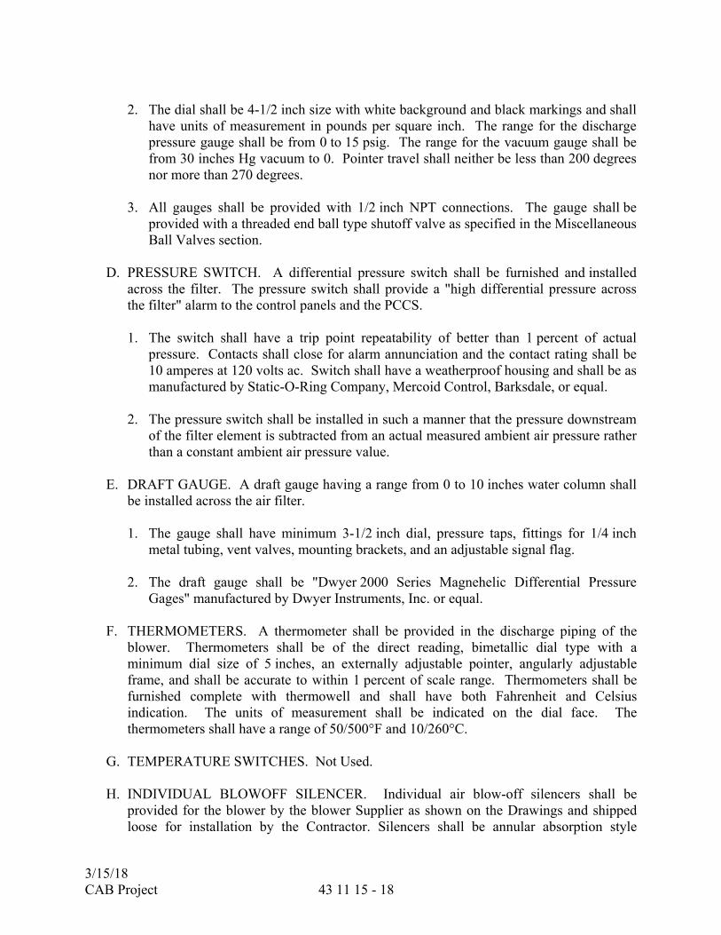
2. The dial shall be 4-1/2 inch size with white background and black markings and shall
have units of measurement in pounds per square inch. The range for the discharge pressure gauge shall be from 0 to 15 psig. The range for the vacuum gauge shall be from 30 inches Hg vacuum to 0. Pointer travel shall neither be less than 200 degrees nor more than 270 degrees.
3. All gauges shall be provided with 1/2 inch NPT connections. The gauge shall be
provided with a threaded end ball type shutoff valve as specified in the Miscellaneous Ball Valves section.
D. PRESSURE SWITCH. A differential pressure switch shall be furnished and installed
across the filter. The pressure switch shall provide a "high differential pressure across the filter" alarm to the control panels and the PCCS.
1. The switch shall have a trip point repeatability of better than 1 percent of actual
pressure. Contacts shall close for alarm annunciation and the contact rating shall be 10 amperes at 120 volts ac. Switch shall have a weatherproof housing and shall be as manufactured by Static-O-Ring Company, Mercoid Control, Barksdale, or equal.
2. The pressure switch shall be installed in such a manner that the pressure downstream of the filter element is subtracted from an actual measured ambient air pressure rather than a constant ambient air pressure value.
E. DRAFT GAUGE. A draft gauge having a range from 0 to 10 inches water column shall
be installed across the air filter.
1. The gauge shall have minimum 3-1/2 inch dial, pressure taps, fittings for 1/4 inch metal tubing, vent valves, mounting brackets, and an adjustable signal flag.
2. The draft gauge shall be "Dwyer 2000 Series Magnehelic Differential Pressure
Gages" manufactured by Dwyer Instruments, Inc. or equal.
F. THERMOMETERS. A thermometer shall be provided in the discharge piping of the blower. Thermometers shall be of the direct reading, bimetallic dial type with a minimum dial size of 5 inches, an externally adjustable pointer, angularly adjustable frame, and shall be accurate to within 1 percent of scale range. Thermometers shall be furnished complete with thermowell and shall have both Fahrenheit and Celsius indication. The units of measurement shall be indicated on the dial face. The thermometers shall have a range of 50/500°F and 10/260°C.
G. TEMPERATURE SWITCHES. Not Used.
H. INDIVIDUAL BLOWOFF SILENCER. Individual air blow-off silencers shall be
provided for the blower by the blower Supplier as shown on the Drawings and shipped loose for installation by the Contractor. Silencers shall be annular absorption style

3/15/18 CAB Project 43 11 15 - 19
employing a single or multi-stage diffuser, and containing an acoustic core to decrease high frequency noise. Packing for the blow-off silencer shall be suitable for low pressure air velocity of up to 7,000 fpm and continuous operation at 300 F. The silencer shall be of all-welded steel construction with prime painted exterior surfaces and flanged connections with diameter and drilling conforming to ANSI B16.1, Class 125. Blow-off silencers shall be sized as indicated on the Drawings. Silencers shall be Stoddard, Universal, or equal.
1. Blowers East Aeration Blowers
West Aeration Blowers
a. Number of Silencer(s). 1 4
b. Silencer(s) tag numbers. S921001
S517511B S517512B S517513B S517514B
I. INDIVIDUAL BLOWER BLOWOFF VALVE. The blowers shall be supplied with one automatically operated blowoff valve to be furnished by the gearless turbo supplier. The blowoff valve shall be as recommended by the blower manufacturer.
1. If the blowoff and/or discharge valve is an integral part of the blower package, it shall
be furnished with the blower. If the valve(s) are not an integral part of the blower, they will be furnished by others and controlled by the blower control panel. Blowoff valve shall be powered from the blower control panel. Dry contact signals available from the valve to the control panel are the following:
a. Valve fully open.
b. Valve fully closed.
c. Valve in AUTO mode.
2. The valve is capable of receiving dry contact OPEN and CLOSE commands from the blower control panel.
3. The sound level shall not exceed 90 dBA at 3 feet from any point of the blower at any operating condition, including periods of blowoff.
4. Blowers East Aeration
Blowers West Aeration Blowers
a. Number of Valve(s). 3 4
b. Valve(s) tag numbers. V921001B V921002B V921003B
V517511B V517512B V517513B V517514B

3/15/18 CAB Project 43 11 15 - 20
J. BUTTERFLY VALVES AND ACTUATORS. Aeration butterfly valves and actuators shall be provided by the gearless turbo supplier as indicated and shall be tagged for identification as indicated on the P&IDs. The butterfly valves shall meet the requirements specified in the BUTTERFLY VALVES Section (40 05 64). The actuators shall meet the requirements specified in the ACTUATORS FOR PROCESS VALVES AND GATES Section (40 05 57).
K. INDIVIDUAL BLOWER DISCHARGE VALVE. The blowers shall each be supplied with one electrically operated discharge valve to be furnished by the gearless turbo supplier. The butterfly valves shall meet the requirements specified in the BUTTERFLY VALVES Section (40 05 64).
1. Blowers East Aeration Blowers
West Aeration Blowers
a. Number of Valve(s). 3 4
b. Valve(s) tag numbers. V921001A V921002A V921003A
V517511A V517512A V517513A V517514A
L. CHECK VALVES. The blowers shall each be supplied with one check valve to be
furnished by the gearless turbo supplier. Check Valves shall have a Class 125 rating, dual disc wafer type, Viton seat, aluminum disc and hinge pins, stainless steel springs with plain ends installed between ASME B16.1 Class 125, flat faced flanges with a temp limit of -20 to 300F. Pressure drop across the valve shall not exceed 0.012 psig. Check valves shall be Crane DuoChek II, Cameron Valves “Silent Seatless Short Form Style 5118 Check Valves”, US Valve of Englewood, NJ, Flexi-Hinge or approved equal. Check Valves shall be tagged as indicated on the drawings and P&IDs.
2.07 NOISE EMISSIONS
A. The blower unit, including the enclosure and openings shall be designed to limit the free field noise emissions to not more than 85 dB(A) at 3 feet from any point of the blower unit when operating at the specified capacity.
2.08 BALANCE
A. All rotating parts shall be accurately machined and shall be in as nearly perfect rotational balance as practicable. Excessive vibrations shall be sufficient cause for rejection of the equipment. The mass of the unit and its distribution shall be such that resonance at normal operating speeds is avoided.
3/15/18 CAB Project 43 11 15 - 21
2.09 DRIVE UNITS
A. The blower shall be the direct drive type driven by a high speed motor.
B. ELECTRIC MOTORS. The blower shall be supplied with a motor rated for, 3 phase, 60 Hz service. The maximum allowable motor horsepower shall be as specified in Paragraph 2.02. The motor shall be a high speed permanent magnet motor. Blower manufacturer shall be responsible for coordinating the starting torque requirement of the blower and the motor. Certified tests shall be submitted to the District Engineer prior to shipment of the equipment.
1. Additional requirements for the blower motors are:
a. Insulation: Epoxy coated or varnished Class H limited to Class H rise.
b. Ambient: 104F ambient.
c. Duty: Continuous.
d. Terminal Boxes: Cast iron, gasketed, separate boxes for motor leads and heater leads. Boxes shall have a ground lug. There shall be a neoprene lead seal separator gasket.
e. Stator Temperature Detector: Two thermal protectors in the stator windings (one each end). Rod and tube type or similar that is sensitive to rate of rise as well as temperature.
f. Bearings: Non-contact magnetic or air bearings rated as specified herein.
g. Nameplate: NEMA standard stainless steel. Additional nameplate information shall also include: NEMA efficiency rating, bearing information, number of starts allowed per hour.
h. Standards: Conform to latest issue of IEEE, ANSI, and NEMA.
i. Ground Pad: There shall be a grounding pad near the base of the motor.
j. High Temperature Shutoff: Control circuit to include high temperature shutoff tied to probe in discharge connection.
2. The motor terminal box shall be sized to accommodate the installation of a current transformer, and all incoming power and control cable as indicated on the Drawings. Current transformers shall be furnished as required for proper control and operation of the blower motors.
2.10 CONTROLS AND CONTROL PANELS
A. BLOWER CONTROL PANEL. The blower control panels shall be equipped with a PLC or microcomputer, an integral operator interface terminal (OIT) and integral adjustable frequency drive (AFD) controller for motor speed control. The control panel shall be integral to the blower package and shall be suitable for the conditions specified herein. The control panel shall be preassembled with the blower unit and pre-tested at the factory

3/15/18 CAB Project 43 11 15 - 22
as a complete assembled unit. All instruments located on the blower package shall be prewired to the blower control panel. The control panel shall contain all necessary controls to open and close the associated blowoff valve and discharge valve. The control panel shall provide fused terminal blocks to provide power to the discharge and blowoff valve actuators. The discharge valve shall be closed when the blower is not in operation. Blower operational controls shall be accessible through a touch screen OIT. The Blower PLC or microcomputer shall communicate with the PLC network using Ethernet Industrial Protocol. If a microcomputer is provided that does not support Ethernet Industrial Protocol a protocol convert shall be supplied and programmed by the Contractor to interface the control system to the PLC network. The blower control panels shall not have hardwired connections to the Area PLC.
1. If PLCs are supplied they shall be Rockwell Automation Allen-Bradley
CompactLogix Series, or ControlLogix Series no Exceptions. PLCs shall be accompanied with the following communication products and configurations.
a. Each PLC shall be provided with two (2) communication modules. One dedicated to for communication with the PCCS, and one dedicated to communication with the OIT.
b. Each control enclosure shall be provided space for a fiber optic patch panel. Minimum space requirements will include 6.5” tall by 5.5” wide and 2” deep.
c. Each control enclosure shall be provided with an Ethernet switch.
2. Main circuit breakers with external operating handle, lockable in the off position, shall be provided. A door interlock shall be provided such that the portion of the control panel which contains 480 volt ac components cannot be opened with the main circuit breaker energized.
3. The blower will only be controlled from the Local OIT, the blower speed, discharge
valve and blowoff valve and all blower related equipment shall be controlled automatically to maintain a pressure or maintain a speed. In automatic (local automatic) all the steps associated with the equipment will execute in an automatic sequence to run the blower and safely shut it down.
4. All blower statuses, alarms, and process values shall be available to the PCCS.
5. All alarm conditions that result in blower shutdown shall require a manual reset from
the blower control panel. All remote annunciation contacts alarming a shutdown condition shall stay in the alarm state until manually reset.
6. Harmonic filters shall be provided for the motor as specified herein.
7. Blower controls shall include built-in vibration, temperature, and pressure sensors.

3/15/18 CAB Project 43 11 15 - 23
8. There shall be three means of shutting down the blower:
a. Normal Stop. Initiated by pushing the local stop feature.
b. Soft Stop. Initiated by high inlet air temperature, high motor temperature, sequence failure, discharge valve is not fully open within two minutes after blower has started, blowoff valve is not fully closed within five minutes after blower has started, high discharge pressure or temperature, high differential pressure across the intake air filter, high motor amps, surge.
c. Emergency Stop. Initiated by pushing "Emergency Stop" button, surge, vibration danger, cabinet door open, or PLC failure, sequence failure during startup.
9. The blower control panels shall limit the number of starts per hour and the minimum time period between starts to values acceptable to the blower and motor manufacturer.
B. SURGE CONTROL. The surge system shall sense unbalance/surge conditions through
the PLC by pressure and flow-sensing devices, specified herein, to prevent a surge condition from damaging the blower. The control system shall prevent an approaching surge condition. Detection of surge conditions shall shut down the blower. The local control panel (LCP) shall provide surge control of the gearless turbo blower by modulating the header blowoff valve as the system pressure rises to a surge condition.
1. Header blowoff on air bearing machines must maintain a header pressure of 4.5 psig at all times to get shaft liftoff.
C. PANEL FABRICATION REQUIREMENTS. The control enclosures shall be rated
NEMA 3R Carbon Steel and shall meet the requirements specified in the CONTROL SYSTEM EQUIPMENT PANELS AND RACKS Section (40 67 00).
D. PROGRAMMABLE LOGIC CONTROLLER (NOT USED)
E. OPERATOR INTERFACE TERMINAL (OIT)
1. OITs shall be Rockwell Automation Allen-Bradley PanelView Plus 6 1500 Model, no
others allowed.
F. INDUSTRIAL ETHERNET SWITCHES:
1. Ethernet Switches shall be Rockwell Automation Stratix Ethernet switch model 1783-BMS10CGN no exceptions.

3/15/18 CAB Project 43 11 15 - 24
G. ADJUSTABLE FREQUENCY DRIVES. The blowers shall be provided with an adjustable frequency drive integral to the blower package. The gearless turbo supplier shall be responsible for furnishing the adjustable frequency drive, for matching the motor and drive, and for coordinating the collection of data and the design effort to limit harmonics to the levels specified below.
1. The adjustable frequency drives (AFD) furnished in the integral blower control panel shall include an input circuit breaker. AFDs shall be UL or ETL listed and shall comply with the latest applicable standards of ANSI, NEMA, IEEE, and the National Electrical Code.
2. The adjustable frequency drives unit shall be an adjustable frequency converter which will convert 480 volts ac (±10 percent), 3 phase, 60 Hz (±2 percent), input power into an adjustable frequency output in an ambient temperature of 40 to 120°F. The drive shall be of sufficient capacity and shall produce a quality output wave form for stepless speed control. The controller shall be suitable for, and coordinated with, the thermal, electrical, and mechanical characteristics of the motor furnished.
3. Six-pulse drives shall be furnished. Drives shall be of the pulse-width modulated type and shall consist of a full-wave diode or gated-open SCR bridge. The rectifier shall convert incoming fixed voltage and fixed frequency to a fixed dc voltage. The pulse-width modulation technology shall be of the space vector type, implemented in a microprocessor that generates a sine-coded output voltage. AFDs shall be equipped with an input line reactor contained within the blower control panel and an externally mounted input harmonic filter.
4. The AFD inverter outputs shall be generated by insulated gate bipolar transistors (IGBT) which shall be controlled by identical base driver circuits. The AFD shall not induce excessive power losses in the motor. The worst case RMS motor line current measured at rated speed, torque, and voltage shall not exceed 1.05 times the rated RMS motor current for pure sine wave operation.
5. The drives shall have self-diagnostics for detection of failed electronic circuitry. All printed circuit boards shall have status indicating lights, or status of each board shall be available from the diagnostic indicators on the drive's LCD display. All diagnostic indicators shall be visible without opening the AFD panel doors. The drive shall include fault detection and trip circuits to protect itself and the connected motor against line voltage transients, over temperature, power line under voltage and overvoltage, and output overcurrent. The drive shall be protected by fast-acting, current limiting input fuses. The drive shall be capable of sustaining 110 percent of motor rated full load current. The drive shall have a current limiting feature to prevent output currents greater than 100 percent of rating. Upon trip-out, the drive shall automatically reset and attempt to restart one time. Upon return of power after outage, the drive shall not automatically restart. Remote or local manual restart shall be required. The drive shall provide electronic isolation between control/logic and power circuits.

3/15/18 CAB Project 43 11 15 - 25
6. Each drive shall have a membrane keypad with integral 2-line, 24 character minimum, LCD display mounted through blower control panel door. The keypad shall be capable of setting all drive parameters and controlling drive operation, including manual/automatic operation modes, start/stop control and alarm/trip reset.
7. The drives shall have microprocessor-based digital logic control fully programmable from the front panel display with nonvolatile memory for the programmed functions. Maximum speed shall be field adjustable. The speed shall increase or decrease at a linear time ramp, independently adjustable for acceleration and deceleration control. The minimum speed (zero point), and the maximum speed (span) shall be independently field adjustable. Local set points shall be entered to the controller via the front panel controls.
8. The input circuit breakers shall be instantaneous-trip type, and shall have an interrupting rating of at least 65,000 amperes at 480 volts.
9. Six-pulse adjustable frequency drives shall be protected from incoming voltage transients with an input ac line reactor. AC line reactors shall be designed to address performance issues of NEMA MG1-20.55 and to provide proper transient protection of the drive input power devices. AC line reactors shall be K-rated per IEEE C57.110 and shall be TCI "Model KLR", or equal.
10. The gearless turbo supplier shall supply input harmonic filters for all blowers with suitable amperage rating at 480 volts ac. Harmonic filters shall be selected for a THD maximum of eight percent (8 percent) at the AFD input terminals when the drive is operating at 100 percent capacity. The harmonic filters shall be installed in the blower control panel. Harmonic filters shall be used on adjustable frequency drives that are not 18-pulse. The filter shall utilize an interlocking contactor which shall be automatically operated by the drive run circuit. Harmonic filters shall be TCI "Harmonic Guard Series", or equal.
11. The adjustable frequency drives shall have Displacement Power Factor of at least 0.95 throughout the entire operating speed range, measured at the drive input terminals.
H. PANEL FACTORY TEST. Before shipment, the blower control panels shall be electrically tested by the manufacturer.
I. PHASE MONITOR. The blower shall be provided with a phase monitor integral to the blower package. The phase monitor shall monitor all 3 phases on the power supply and shall and shall trip the unit if the phase imbalance is greater than 110% or less than 90% of the nominal value and cause the package to shut down in a controlled manner. The phase monitor shall also open the blower package blowoff valve immediately up detection of a phase imbalance.

3/15/18 CAB Project 43 11 15 - 26
2.11 SHOP TEST
A. Blowers shall be shop tested over the capacity range from just above surge to maximum rated flow to verify wire-to-air package power consumption and generate a performance curve as specified in the Performance Test paragraph. In advance of shop testing, test procedures shall be submitted to the District Representative for review and acceptance. Procedures shall include calibration certificates for instruments verifying calibration within the previous 12 months and test setup drawings, pressure instrument calibration procedures, as well as blank data sheets. Following testing and prior to shipment of blowers to the site, test reports shall be submitted for review and acceptance. Reports shall include data collected, performance curves, and equations for adjusting test data to contract conditions, and a sample calculation for one test point as well as flow measurement instrument data.
B. BALANCING AND OVERSPEED TESTING. Impellers shall be dynamically balanced and if welded, shall be subjected to an overspeed test of not less than 115 percent of the maximum operating speed. If the impeller is fabricated, following the overspeed test, the impeller shall be carefully inspected for defects using the dye penetrant method or another equivalent method. Rotor assemblies shall be dynamically balanced. Overspeed certificate, if required, and rotor balancing reports shall be delivered to the District Engineer at least 21 days prior to the shipment of the blowers from the manufacturer.
C. OPERATIONAL TEST. The blower shall be shop tested for vibration and pressure developed.
D. PERFORMANCE TEST. If PTC-13 has been issued, it shall be used. Otherwise PTC-10 shall be used. The wire-to-air package power consumption determined by the performance testing shall comply with either the maximum guaranteed package wire-to-air power consumption specified herein or the package wire-to-air power consumption submitted during the submittal review process, whichever is more stringent. Liquidated damages shall be assessed in the same manner. All blowers shall be shop tested for capacity, discharge pressure, wire power requirements, and efficiency at the rated capacity, reduced speed capacity, and at as many other capacities as necessary for accurate performance curve plotting. The tests shall be performed in accordance with the manufacturer's standard methods. If PTC 13 is not yet issued and PTC 10 is used, the version that was reaffirmed in 1986 shall be used. Flow shall be measured in strict accordance with ASME PTC-10 and 19.5 and shall be measured on the discharge side of the blower. Test procedure information, as well as test results, shall be submitted in accordance with the requirements of the Submittals paragraph. The test arrangement drawing shall include pipe sizes, instrument locations including dimensioned spacings of instruments, instrument ranges types, and models. A differential pressure sensor shall be used across the flow measurement device. Separate inlet and outlet pressure sensors shall not be acceptable. Instrument ranges shall be such that the readings are near the midpoint of the range. Dynamic pressure shall be determined downstream of the discharge cone. The test shall include measurement of discharge pressure and discharge air temperature. Piping from the blower discharge to the discharge temperature measurement location shall be insulated with a minimum of 1 inch thick mineral fiber insulation with a
3/15/18 CAB Project 43 11 15 - 27
maximum thermal conductivity value of 0.24 Btu in/hr ft2 °F at 75°F and shall comply with ASTM C547.
1. During testing constant volumetric flow and constant isentropic head shall be maintained between contract and shop test conditions. If this is not possible for shop conditions due to inadequate motor sizing, the blower may be operated at a reduced speed while using dimensionless parameters for flow, pressure, and efficiency as described in PTC-10.
2. Until PTC-13 has been issued, it is acceptable to test the blower core per ASME PTC-10 requirements and then perform a package performance test to account for additional, parasitic electrical losses.
3. Input wire power shall be measured using a calibrated wattmeter. For inverter applications, the power measuring device shall have the ability to measure the corrupted sine wave through the 13th harmonic and shall not be based on normal 50/60Hz RMS sine wave for power analysis. Measured total power shall be wire-to-air and shall include all losses associated with electrical shaft power, including, but not limited to the motor, inverter, harmonic filter, and cooling system, if used. Input wire power shall exclude any power used for air conditioning cabinet for the electrical compartment.
4. The enclosure cooling system shall be operational during shop performance testing. Any electrical power required for cooling shall be measured as part of the input power measurement and the effect of any increased inlet process air temperature due to its being used for cooling shall be taken into consideration in determining system mass flow rate.
5. Adequate operating points shall be recorded to generate a test curve through the rated point. In addition, the minimum air flow point shall be verified. For each test operating point used to generate the test curve, three readings shall be taken at four measurement locations 90 degrees apart around the circumference of the pipe for each of the following, as required by ASME PTC-10:
a. Atmospheric pressure
b. Ambient temperature
c. Relative humidity
d. Inlet pressure
e. Inlet temperature
f. Discharge pressure
g. Discharge temperature
h. Temperature upstream or downstream of flow measurement device
i. Pressure upstream of flow measurement device
j. Differential pressure across flow measurement device
3/15/18 CAB Project 43 11 15 - 28
6. During testing, the speed required to produce the specified actual inlet volumetric flow (acfm) and design isentropic head shall be determined for each design guarantee point. The machine shall be operated at the required speed so that a speed correction is not needed. The specified actual inlet volumetric flow (icfm) and design isentropic head for the design guarantee point being tested shall also be matched during testing. If this is not possible at shop conditions due to inadequate motor size, the motor may be operated at reduced speed while using dimensionless parameters for flow, pressure, and efficiency as described in PTC-10. Isentropic head established during testing shall include inlet filter and package losses, in addition to inlet losses as required per contract.
7. The surge margin shall be determined for each design guarantee point by holding the speed required at that point constant and determining the surge pressure. If the required 0.3 psi rise to surge cannot be achieved at constant speed, the shop test shall demonstrate that a 0.3 psi rise to surge can be achieved by increase speed without increasing flow.
8. Steady state is defined as the condition in which changes in temperature rise and isentropic efficiency within a five minute interval is less than 0.5°C (0.9°F) and 0.5%, respectively.
9. Air flow shall be measured on the discharge side of the blower and corrected to the inlet conditions.
10. Failure to comply with ASME PTC-10 or PTC-13 and testing requirements specified herein shall be sufficient cause for rejection of the equipment.
11. Test procedures shall be submitted in accordance with the Submittals section to District Representative at least 45 days prior to the testing. At least 30 days prior to the test, notice shall be given by Contractor to the District Representative.
12. The equipment shall be performance tested as a package in the manner it will operate when installed. The equipment shall be performance tested with the contract motor and VFD with the enclosure doors closed. The test results shall be adjusted by taking into account the specified inlet filter pressure loss. Any losses from the inlet filter to the package inlet shall be accounted for in the test report and head evaluation during testing. The contract harmonic filter shall also be tested. All power consuming components shall be included in the wire power measurement.
13. District Representative will witness shop tests, inspect and check testing equipment used, and observe the calibration of pressure gauges and transducers. Pressure measurement devices calibrated at a location remote from the factory will not be acceptable. All readings are to be read manually from the certified and/or calibrated instruments. The use of computer data acquisition systems shall not be acceptable. As an alternative if used, a local direct readout shall be provided at each measurement location and direct readings shall match the data acquisition system readings within the tolerances of ASME PTC-10.

3/15/18 CAB Project 43 11 15 - 29
14. The equipment manufacturer shall furnish all air and ground transportation, lodging, miscellaneous travel expenses, and meals for two representatives of District Representative and two representatives of the District for the duration of the testing of the blower and panel and necessary subsequent testing necessitated by failed tests.
15. Calibration certificates for all other instruments shall be submitted and shall indicate calibration within the previous 12 months. Calculations shall be performed to correct test data to the specified site conditions. Corrected data shall be used to plot performance curves. Curves shall include inlet cfm versus discharge pressure, inlet cfm versus package power draw and inlet cfm versus efficiency. Curves shall be plotted using specified site conditions for both summer and winter inlet air temperature and relative humidity conditions specified. The blower serial number shall be indicated on the corresponding performance curve. The Reynolds number correction shall be excluded in this case.
16. During shop testing, power factor shall be recorded, certified by the testing technician, and submitted to verify compliance with the specification.
17. Each enclosure shall be checked for leakage in the field. The intent of the leakage test is to ensure that no unfiltered air enters the blower package. Either a smoke test with a beekeeper's smoker shall be used or a paper test shall be performed. For the paper test, a 4" x 4" square of tissue paper shall be used. With the blower operating at rated air flow and pressure, all enclosure seams and panels shall be tested by either directing the smoke at the seams or holding the paper against the seams to see if it is pulled against the enclosure by suction pressure. If any leakage is found, the manufacturer shall correct such that there is no possibility of unfiltered air entering the enclosure. Correction methods shall be permanent. Silicon caulking, for example, is not acceptable because it is not considered to be a permanent solution.
18. No minus tolerance on discharge pressure or flow shall be allowed. Package power draw specified shall be guaranteed ± 4 percent or to the manufacturer's standard tolerance, whichever is more stringent. In no case shall the package power draw indicated by shop tests and corrected to specified site conditions exceed the motor nameplate rating. Exceeding the motor nameplate rating shall be sufficient cause for rejecting the equipment.
19. Six certified copies of the test report complete with performance curves, data, and all calculations shall be submitted in accordance with the Submittals section. The test reports shall be delivered to the District Representative at least 21 days prior to the shipment of the blowers from the manufacturer.
3/15/18 CAB Project 43 11 15 - 30
E. HARMONIC MITIGATION EQUIPMENT. Harmonic mitigation equipment shall be supplied to meet the harmonic standards of IEEE 519. Harmonic mitigation shall be provided by the blower manufacturer for the blower unit and shall comply with the requirements specified herein.
1. Electrical Harmonic Analysis. Submit detailed electrical calculations demonstrating
compliance with the harmonic requirements specified herein.
a. For the purposes of the harmonic analysis, assume all units are operating excluding any standby units not required to achieve rated system capacity.
b. Voltage distortion for each condition shall comply with the IEEE 519 total harmonic distortion and notching criteria for General Systems. Current distortion limits shall comply with the individual harmonic order limits indicated in IEEE 519, Table 10.3. System short circuit at the point of common coupling is 35,000 amperes. Maximum plant load current is 1,000 amperes.
c. The harmonic analysis shall include:
1) All input data and assumptions. Provide an impedance diagram illustrating the simulated system.
2) Explanation of methods used to perform the study.
3) Explanation of study results with specific recommendations on harmonic mitigation measures that will be implemented to achieve the specified limits.
4) All calculations and computer printouts used to arrive at the conclusions and recommendations. Include one sample calculation and define all variables and constants.
5) Individual blower harmonic content and the combined total drives harmonic content reflected in the system supply voltage as a percent of the 60 Hz fundamental under actual load conditions from no-load to full load in 10 percent load increments.
6) Provide a bar chart graph(s) comparing the harmonics produced by the AFD without the input filter and with the input filter at 60 and 100 percent speeds.
7) Analysis shall be stamped and signed by a registered electrical engineer.
F. REMEDIES/LIQUIDATED DAMAGES. In the event that any part(s) of the aeration blower systems fail(s) to meet the guaranteed specified or submitted(1) performance requirements, the gearless turbo supplier shall guarantee that at their sole expense, they will exercise one or both of the following options:
Provide all necessary material and personnel to modify the system to meet the specified performance requirements and rerun the performance tests until satisfactory results are achieved.
Remove that part(s) of the system that is not operating properly and replace it with equipment that meets the necessary performance criteria.
3/15/18 CAB Project 43 11 15 - 31
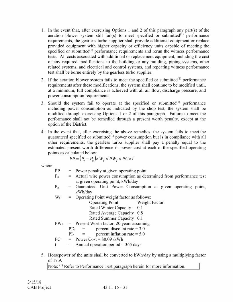
1. In the event that, after exercising Options 1 and 2 of this paragraph any part(s) of the aeration blower system still fail(s) to meet specified or submitted(1) performance requirements, the gearless turbo supplier shall provide additional equipment or replace provided equipment with higher capacity or efficiency units capable of meeting the specified or submitted(1) performance requirements and rerun the witness performance tests. All costs associated with additional or replacement equipment, including the cost of any required modifications to the building or any building, piping systems, other related systems, and electrical and control systems, and repeating witness performance test shall be borne entirely by the gearless turbo supplier.
2. If the aeration blower system fails to meet the specified or submitted(1) performance requirements after these modifications, the system shall continue to be modified until, at a minimum, full compliance is achieved with all air flow, discharge pressure, and power consumption requirements.
3. Should the system fail to operate at the specified or submitted(1) performance including power consumption as indicated by the shop test, the system shall be modified through exercising Options 1 or 2 of this paragraph. Failure to meet the performance shall not be remedied through a present worth penalty, except at the option of the District.
4. In the event that, after exercising the above remedies, the system fails to meet the guaranteed specified or submitted(1) power consumption but is in compliance with all other requirements, the gearless turbo supplier shall pay a penalty equal to the estimated present worth difference in power cost at each of the specified operating points as calculated below:
tPCPWWPPPP ffga
where: PP = Power penalty at given operating point Pa = Actual wire power consumption as determined from performance test
at given operating point, kWh/day Pg = Guaranteed Unit Power Consumption at given operating point,
kWh/day Wf = Operating Point weight factor as follows:
Operating Point Weight Factor Rated Winter Capacity 0.1 Rated Average Capacity 0.8 Rated Summer Capacity 0.1
PWf = Present Worth factor, 20 years assuming PDr = percent discount rate = 3.0 PIr = percent inflation rate = 5.0 PC = Power Cost = $0.09 /kWh t = Annual operation period = 365 days
5. Horsepower of the units shall be converted to kWh/day by using a multiplying factor of 17.9. Note: (1) Refer to Performance Test paragraph herein for more information.

3/15/18 CAB Project 43 11 15 - 32
2.12 SHOP COATINGS
A. Prepare, prime, and finish coat equipment and appurtenances with manufacturer’s standard coating system. Field coating shall be in accordance with the PAINTING AND COATING Section (09 90 00).
PART 3 - EXECUTION
3.01 INSTALLATION
A. The blower units will be installed in accordance with Equipment Installation section. The Contractor shall furnish, install, and place in service the blower and all appurtenances in accordance with the manufacturer's recommendations. The gearless turbo supplier shall supply blower packages shipped completely pre-assembled. Only the electrical connections and pipe connections shall be performed on site by the Contractor.
B. Unless otherwise indicated or specified, the blower units will be installed on concrete bases at least 6 inches high. Vibration isolation pads will be installed between the blower unit baseplate and the concrete base. Anchor bolts shall be utilized as locating pins and nuts shall be installed only finger-tight. Anchor bolt threads shall be dislocated or stripped to prevent tightening beyond finger-tight.
C. Inlet pipe between inlet filter and blower package shall be kept in clean condition. If the package includes a process side panel filter in series with the remotely mounted cartridge filter, the panel filter shall remain in place for two weeks after startup to capture any debris present in the inlet piping.
D. Contractor shall be fully responsible for installing all equipment in this section and conducting startup and testing in accordance with the equipment manufacturer's written recommendations and/or requirements specified herein. The Contractor shall include in his costs all assistance required of the manufacturer to ensure proper installation; provide startup and testing assistance; and train the District's personnel.
3.02 FIELD QUALITY CONTROL
A. Installation Check. An experienced, competent, and authorized representative of the manufacturer shall visit the site of the Work and inspect, check, adjust if necessary, and approve the equipment installation. The representative shall be present when the equipment is placed in operation in accordance with the Startup Requirements section, and shall revisit the job site as often as necessary until all trouble is corrected and the equipment installation and operation are satisfactory in the opinion of the Engineer.
1. The manufacturer's representative shall furnish a written report certifying that
the equipment has been properly installed; is in accurate alignment; is free from any undue stress imposed by connecting piping or anchor bolts; and has been operated under full load conditions and that it operated satisfactorily.
3/15/18 CAB Project 43 11 15 - 33
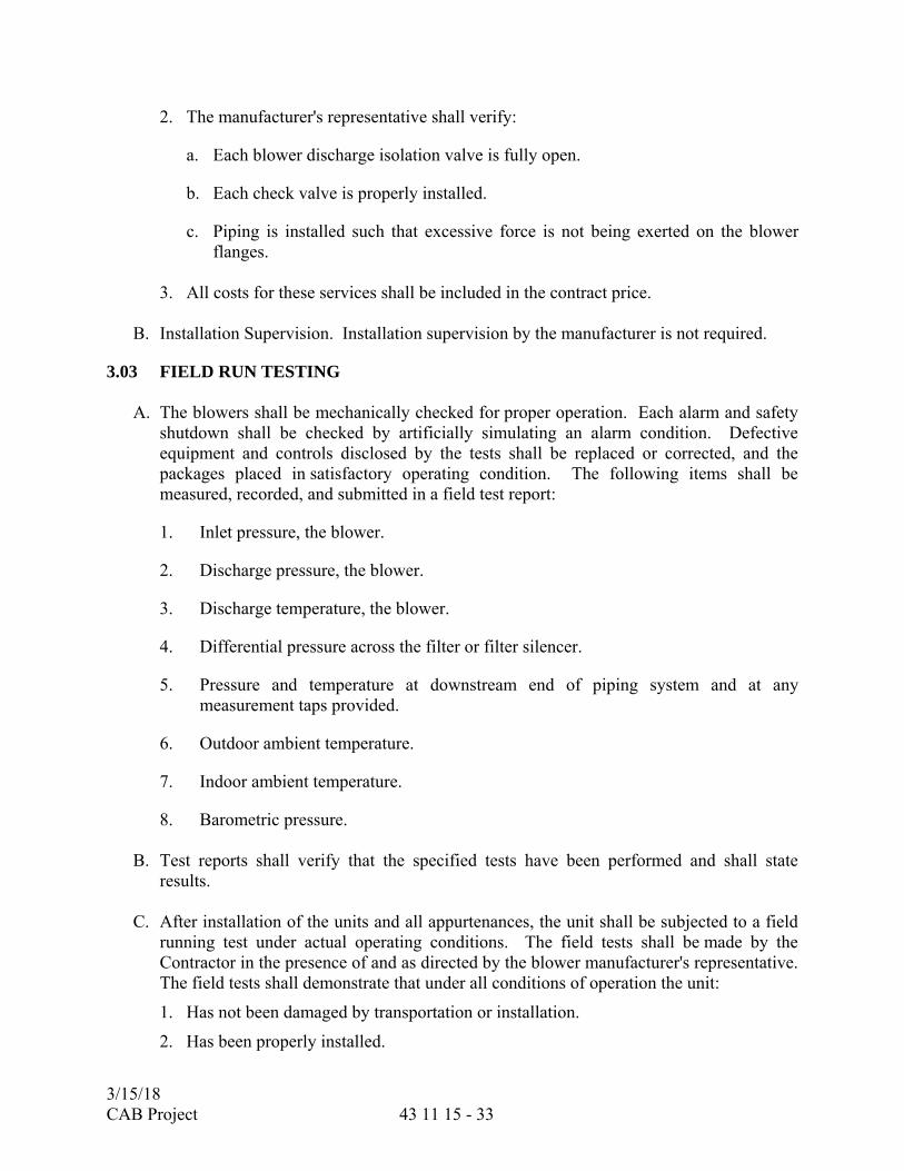
2. The manufacturer's representative shall verify:
a. Each blower discharge isolation valve is fully open.
b. Each check valve is properly installed.
c. Piping is installed such that excessive force is not being exerted on the blower flanges.
3. All costs for these services shall be included in the contract price.
B. Installation Supervision. Installation supervision by the manufacturer is not required.
3.03 FIELD RUN TESTING
A. The blowers shall be mechanically checked for proper operation. Each alarm and safety shutdown shall be checked by artificially simulating an alarm condition. Defective equipment and controls disclosed by the tests shall be replaced or corrected, and the packages placed in satisfactory operating condition. The following items shall be measured, recorded, and submitted in a field test report:
1. Inlet pressure, the blower.
2. Discharge pressure, the blower.
3. Discharge temperature, the blower.
4. Differential pressure across the filter or filter silencer.
5. Pressure and temperature at downstream end of piping system and at any measurement taps provided.
6. Outdoor ambient temperature.
7. Indoor ambient temperature.
8. Barometric pressure.
B. Test reports shall verify that the specified tests have been performed and shall state results.
C. After installation of the units and all appurtenances, the unit shall be subjected to a field
running test under actual operating conditions. The field tests shall be made by the Contractor in the presence of and as directed by the blower manufacturer's representative. The field tests shall demonstrate that under all conditions of operation the unit:
1. Has not been damaged by transportation or installation.
2. Has been properly installed.
3/15/18 CAB Project 43 11 15 - 34
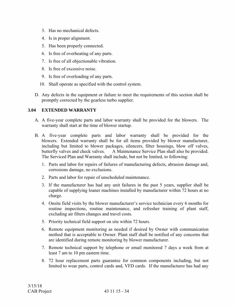
3. Has no mechanical defects.
4. Is in proper alignment.
5. Has been properly connected.
6. Is free of overheating of any parts.
7. Is free of all objectionable vibration.
8. Is free of excessive noise.
9. Is free of overloading of any parts.
10. Shall operate as specified with the control system.
D. Any defects in the equipment or failure to meet the requirements of this section shall be promptly corrected by the gearless turbo supplier.
3.04 EXTENDED WARRANTY
A. A five-year complete parts and labor warranty shall be provided for the blowers. The warranty shall start at the time of blower startup.
B. A five-year complete parts and labor warranty shall be provided for the blowers. Extended warranty shall be for all items provided by blower manufacturer, including but limited to blower packages, silencers, filter housings, blow off valves, butterfly valves and check valves. A Maintenance Service Plan shall also be provided. The Serviced Plan and Warranty shall include, but not be limited, to following:
1. Parts and labor for repairs of failures of manufacturing defects, abrasion damage and, corrosions damage, no exclusions.
2. Parts and labor for repair of unscheduled maintenance.
3. If the manufacturer has had any unit failures in the past 5 years, supplier shall be capable of supplying loaner machines installed by manufacturer within 72 hours at no charge.
4. Onsite field visits by the blower manufacturer’s service technician every 6 months for routine inspections, routine maintenance, and refresher training of plant staff, excluding air filters changes and travel costs.
5. Priority technical field support on site within 72 hours.
6. Remote equipment monitoring as needed if desired by Owner with communication method that is acceptable to Owner. Plant staff shall be notified of any concerns that are identified during remote monitoring by blower manufacturer.
7. Remote technical support by telephone or email monitored 7 days a week from at least 7 am to 10 pm eastern time.
8. 72 hour replacement parts guarantee for common components including, but not limited to wear parts, control cards and, VFD cards. If the manufacturer has had any
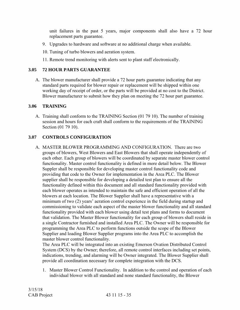
3/15/18 CAB Project 43 11 15 - 35
unit failures in the past 5 years, major components shall also have a 72 hour replacement parts guarantee.
9. Upgrades to hardware and software at no additional charge when available.
10. Tuning of turbo blowers and aeration system.
11. Remote trend monitoring with alerts sent to plant staff electronically.
3.05 72 HOUR PARTS GUARANTEE
A. The blower manufacturer shall provide a 72 hour parts guarantee indicating that any standard parts required for blower repair or replacement will be shipped within one working day of receipt of order, or the parts will be provided at no cost to the District. Blower manufacturer to submit how they plan on meeting the 72 hour part guarantee.
3.06 TRAINING
A. Training shall conform to the TRAINING Section (01 79 10). The number of training session and hours for each craft shall conform to the requirements of the TRAINING Section (01 79 10).
3.07 CONTROLS CONFIGURATION
A. MASTER BLOWER PROGRAMMING AND CONFIGURATION. There are two groups of blowers, West Blowers and East Blowers that shall operate independently of each other. Each group of blowers will be coordinated by separate master blower control functionality. Master control functionality is defined in more detail below. The Blower Suppler shall be responsible for developing master control functionality code and providing that code to the Owner for implementation in the Area PLC. The Blower supplier shall be responsible for developing a detailed test plan to ensure all the functionality defined within this document and all standard functionality provided with each blower operates as intended to maintain the safe and efficient operation of all the blowers at each location. The Blower Supplier shall have a representative with a minimum of two (2) years’ aeration control experience in the field during startup and commissioning to validate each aspect of the master blower functionality and all standard functionality provided with each blower using detail test plans and forms to document that validation. The Master Blower functionality for each group of blowers shall reside in a single Contractor furnished and installed Area PLC. The Owner will be responsible for programming the Area PLC to perform functions outside the scope of the Blower Supplier and loading Blower Supplier programs into the Area PLC to accomplish the master blower control functionality. The Area PLC will be integrated into an existing Emerson Ovation Distributed Control System (DCS) by the Owner; therefore, all remote control interfaces including set points, indications, trending, and alarming will be Owner integrated. The Blower Supplier shall provide all coordination necessary for complete integration with the DCS.
1. Master Blower Control Functionality. In addition to the control and operation of each individual blower with all standard and none standard functionality, the Blower

3/15/18 CAB Project 43 11 15 - 36
Supplier shall provide Master Blower control functionality for each group of blowers East Blowers and West Blowers. The minimum functionality shall include the following. a) Lead/Lag/Standby Operation. The Blower Supplier shall be responsible for
developing code that allows the Operator to select the lead, lag, and standby operation of each group of blowers separately. The logic must accommodate all combinations of blower lead, lag, and standby assignments. When the blowers are operating in a remote control (not local control) the blowers will be started and stopped based on the capacity needs of the system and the best achievable energy efficiency. When the overall capacity of a give system calls for one blower to efficiently deliver the required air then the system will start the Lead blower. Subsequent lag blowers shall be started in the most energy efficient way possible to provide increase capacity demand for air. Lag blowers shall be stopped in the most energy efficient way possible when demand for air decreases overall capacity required. Hysteresis shall be provided between the start and stop of lag blowers to prevent repeated and rapid starts and stops. If the operator changes the lead- lag sequence, the blowers will immediately start and stop as needed to accommodate the change. This functionality shall be validated by the Engineer, Blower Supplier, and Owner during final startup and commissioning.
b) Header Pressure Control. The Blower Supplier shall be responsible for developing code that allows the Operator to control the header pressure while running all blowers at the same speed for each group of blowers. Pressure shall be controlled by a Proportional-Integral-Derivative (PID) controller. Logic shall be included to ramp up starting blowers and ramp down stopping blowers with long enough ramp times to allow the PID controller to react the change in the number of blowers operating. Logic shall be designed to maintain highest energy efficiency possible. This functionality shall be validated by the Engineer, Blower Supplier, and Owner during final startup and commissioning.
c) Combined Flow Control. The Blower Supplier shall be responsible for developing code that allows the Operator to control the overall air flow. The logic shall divide up a single flow set point and send it to the appropriate number of blowers to achieve the flow capacity in the most energy efficient way. This functionality shall be validated by the Engineer, Blower Supplier, and Owner during final startup and commissioning.
B. PLC ARRANGEMENT AND CONFIGURATION. The PLC shall be configured to perform all control functionality defined in this specification and shall be configured to interface with the District’s PCCS. The PCCS will be configured by District; however, the Contractor shall design and configure the controls to allow the District to perform remote monitoring from the PCCS. To ensure coordination of controls the Contractor shall attend two (2) control integration workshops with the District for coordinating the controls and with the District PCCS system.
3/15/18 CAB Project 43 11 15 - 37
C. INDUSTRIAL ETHERNET SWITCH CONFIGURATION. The configuration settings of the Ethernet switches shall be coordinated with the District’s control system network which will be provided at the workshop. The Contractor shall be required to attend two (2) workshops with the District to ensure that the switches are configured for seamless integration into the overall network schema. All aspects of the network configuration shall be documented and agreed upon at the workshops. Topics discussed at the workshops shall include but is not limited to virtual local area networks, quality of service, and internet protocol addressing for all equipment. The Contractor shall bring an experienced network programmer to the workshop for the discussion where they will be prepared to present their resume. If the Construction Manager or the District determine that the Contractor’s network configuration personnel is not qualified the workshop obligations shall not be meet and the Contractor shall reschedule the workshop. All network configuration files shall be turned over to the District for review upon request at any time during the configuration of the Ethernet Switches. Final documentation of the configuration shall be submitted in the O&M manual.
D. CONFIGURATION WORKSHOPS, MEETINGS, AND REQUIREMENTS. The Blower Supplier, Owner, and PMO shall attend and/or conduct configuration and programming coordination workshops.
1. Kick-off Meeting
a) Objectives of this meeting includes the following:
1) Introduction of the programming team members
2) Establish regular coordination call schedule (fortnightly, a total of eight (8) calls four (4) hours each shall be planned.)
3) Owner to provide and explain in detail the graphical programming standards required for the blower OIT screens.
4) Blower Supplier to provide descriptions of all the blower equipment functionality and features.
5) Owner to provide software versions to be used by Blower Supplier for code development.
6) PLC Tag naming convention shall be established by the Owner.
7) PLC programming documentation requirements.
b) The meeting duration shall be four (4) hours held onsite at the Owners facilities.
c) Prior to starting any programming the Blower Supplier shall attend this meeting and obtain detailed understanding of the objectives at the Kick-off meeting as documented. Any programming conducted before the Kick-off meeting that does not meet the requirements provided in the meeting shall be redone at no additional cost to the Owner.
d) Blower Supplier shall provide meeting agenda items to the Contractor and PMO.
3/15/18 CAB Project 43 11 15 - 38
2. Coordination Phone Meetings
a) Objectives of this meeting include the following:
1) Discuss and finalize OIT screen layout and functionality
2) Discuss individual blower control logic
3) Discuss master blower control logic
4) Discuss transferring data between blower controller and Area PLC
5) Discuss project documentation
6) Discuss testing procedures, forms, and validation documentation at startup.
b) Meeting duration shall be four (4) hours
c) The Blower Supplier shall submit agenda topics and documentation of these meetings.
d) All OIT, individual blower control programming, and master blower control programming shall be completed prior to the FAT.
e) Testing procedures and forms applicable to the FAT shall be refined for field testing and validation.
**END OF SECTION**
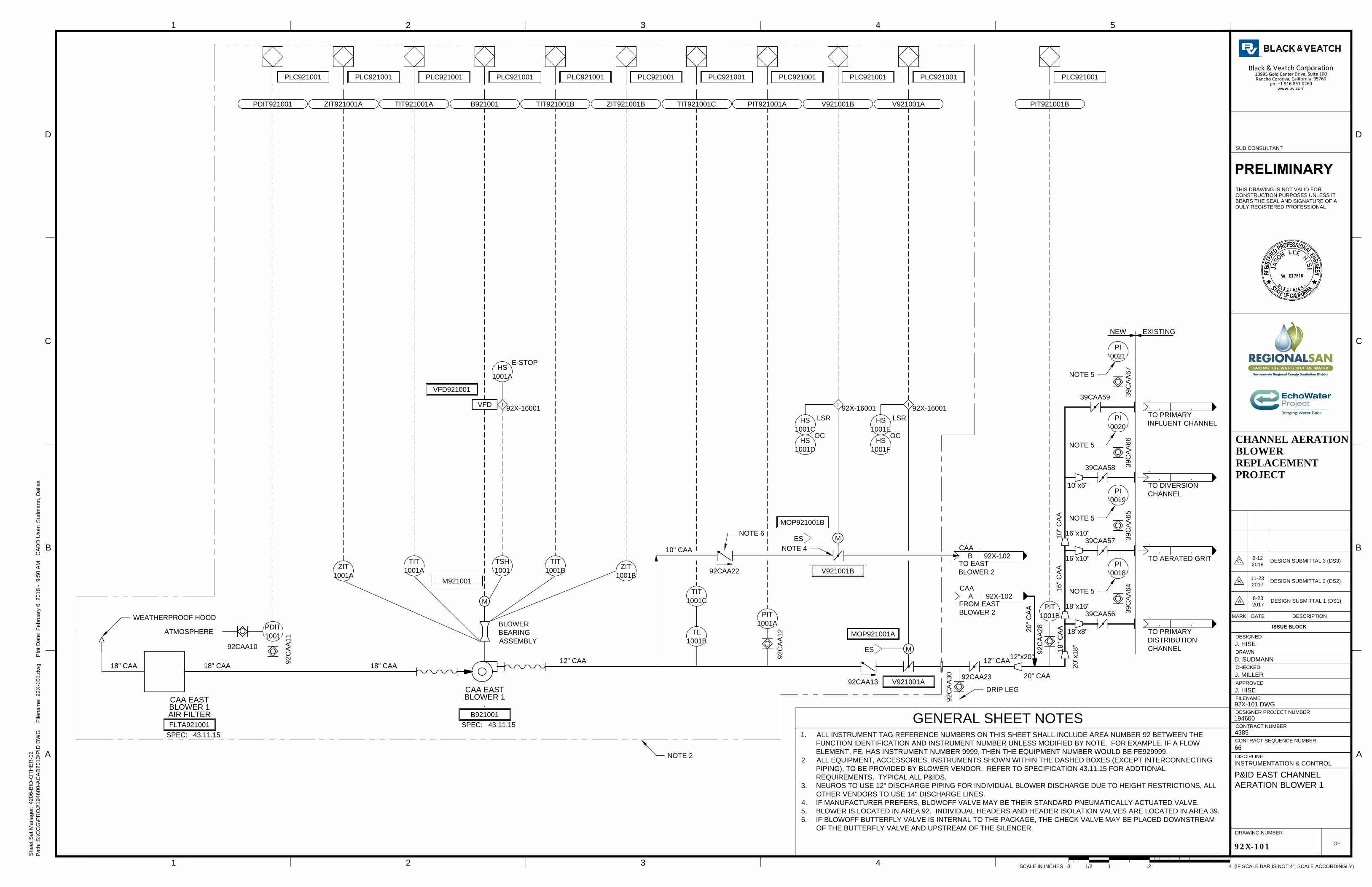
18" CAA 18" CAA
92CAA13
12" CAA12" CAA
TIT
1001C
92C
AA
12
PIT
1001A
92C
AA
11
92CAA10
I
92X-16001
B921001 V921001A
I
92X-16001
VFD921001
VFD
SPEC:
B921001
43.11.15
.
BLOWER 1
CAA EAST
TIT
1001B
TIT
1001A
ZIT
1001A
ZIT
1001B
TIT921001BTIT921001AZIT921001A
PDIT
1001
TIT921001C PIT921001A V921001B
LSR
HS
1001C
I
92X-16001
OC
HS
1001D
PDIT921001
PLC921001
ZIT921001B
BLOWER
BEARING
ASSEMBLY
ATMOSPHERE
PLC921001 PLC921001 PLC921001 PLC921001 PLC921001 PLC921001 PLC921001 PLC921001 PLC921001
TSH
1001
NOTE 2
LSR
HS
1001E
OC
HS
1001F
TE
1001B
SPEC:
FLTA921001
43.11.15
AIR FILTER
BLOWER 1
CAA EAST
M921001
M
A .
CAA
FROM EAST
BLOWER 2
92X-102
WEATHERPROOF HOOD
MOP921001B
M
V921001B
20" C
AA
12"x20"
20" CAA
18" CAA
39CAA56
39CAA57
39CAA58
39CAA59
. .
.
TO PRIMARY
INFLUENT CHANNEL
. .
.
TO DIVERSION
CHANNEL
. .
.
TO AERATED GRIT
. .
.
TO PRIMARY
DISTRIBUTION
CHANNEL
NEW EXISTING
B .
CAA
TO EAST
BLOWER 2
92X-102
10" CAA
18"x8"
18"x16"
16"x10"
16"x10"
10"x6"
16" C
AA
10" C
AA
NOTE 4
20"x18"
18" C
AA
MOP921001A
M
V921001A
PI
0021
39C
AA
67
PI
0018
39C
AA
64
PI
0019
39C
AA
65
PI
0020
39C
AA
66
ES
ES
E-STOP
HS
1001A
NOTE 5
NOTE 5
NOTE 5
NOTE 5
92CAA22
92CAA23
NOTE 6
92C
AA
28
PIT
1001B
PIT921001B
PLC921001
92C
AA
30
DRIP LEG
1
CHECKED
APPROVED
DRAWN
DESIGNED
2 3 4 5
B
C
D
B
C
D
A
OF
FILENAME
DESIGNER PROJECT NUMBER
CONTRACT NUMBER
DRAWING NUMBER
ISSUE BLOCK
MARK DATE DESCRIPTION
CONTRACT SEQUENCE NUMBER
DISCIPLINE
1 2 3 4
(IF SCALE BAR IS NOT 4", SCALE ACCORDINGLY)SCALE IN INCHES 411/20 2
Path: S
:\C
CG
\P
RO
J\194600-A
CA
D2013\P
ID
D
WG
F
ilenam
e: 92X
-101.dw
g P
lot D
ate: F
ebruary 6, 2018 - 9:50 A
M C
AD
D U
ser: S
udm
ann, D
allas
A
Sheet S
et M
anager: 4206-B
ID
-O
TH
ER
-02
PRELIMINARY
THIS DRAWING IS NOT VALID FOR
CONSTRUCTION PURPOSES UNLESS IT
BEARS THE SEAL AND SIGNATURE OF A
DULY REGISTERED PROFESSIONAL
SUB CONSULTANT
CHANNEL AERATIONBLOWERREPLACEMENTPROJECT
92X-101
P&ID EAST CHANNEL
AERATION BLOWER 1
INSTRUMENTATION & CONTROL
66
4385
194600
92X-101.DWG
J. HISE
J. MILLER
D. SUDMANN
J. HISE
A
8-23
2017
DESIGN SUBMITTAL 1 (DS1)
B
11-23
2017
DESIGN SUBMITTAL 2 (DS2)
C
2-12
2018
DESIGN SUBMITTAL 3 (DS3)
1. ALL INSTRUMENT TAG REFERENCE NUMBERS ON THIS SHEET SHALL INCLUDE AREA NUMBER 92 BETWEEN THE
FUNCTION IDENTIFICATION AND INSTRUMENT NUMBER UNLESS MODIFIED BY NOTE. FOR EXAMPLE, IF A FLOW
ELEMENT, FE, HAS INSTRUMENT NUMBER 9999, THEN THE EQUIPMENT NUMBER WOULD BE FE929999.
2. ALL EQUIPMENT, ACCESSORIES, INSTRUMENTS SHOWN WITHIN THE DASHED BOXES (EXCEPT INTERCONNECTING
PIPING), TO BE PROVIDED BY BLOWER VENDOR. REFER TO SPECIFICATION 43.11.15 FOR ADDTIONAL
REQUIREMENTS. TYPICAL ALL P&IDS.
3. NEUROS TO USE 12" DISCHARGE PIPING FOR INDIVIDUAL BLOWER DISCHARGE DUE TO HEIGHT RESTRICTIONS, ALL
OTHER VENDORS TO USE 14" DISCHARGE LINES.
4. IF MANUFACTURER PREFERS, BLOWOFF VALVE MAY BE THEIR STANDARD PNEUMATICALLY ACTUATED VALVE.
5. BLOWER IS LOCATED IN AREA 92. INDIVIDUAL HEADERS AND HEADER ISOLATION VALVES ARE LOCATED IN AREA 39.
6. IF BLOWOFF BUTTERFLY VALVE IS INTERNAL TO THE PACKAGE, THE CHECK VALVE MAY BE PLACED DOWNSTREAM
OF THE BUTTERFLY VALVE AND UPSTREAM OF THE SILENCER.
GENERAL SHEET NOTES
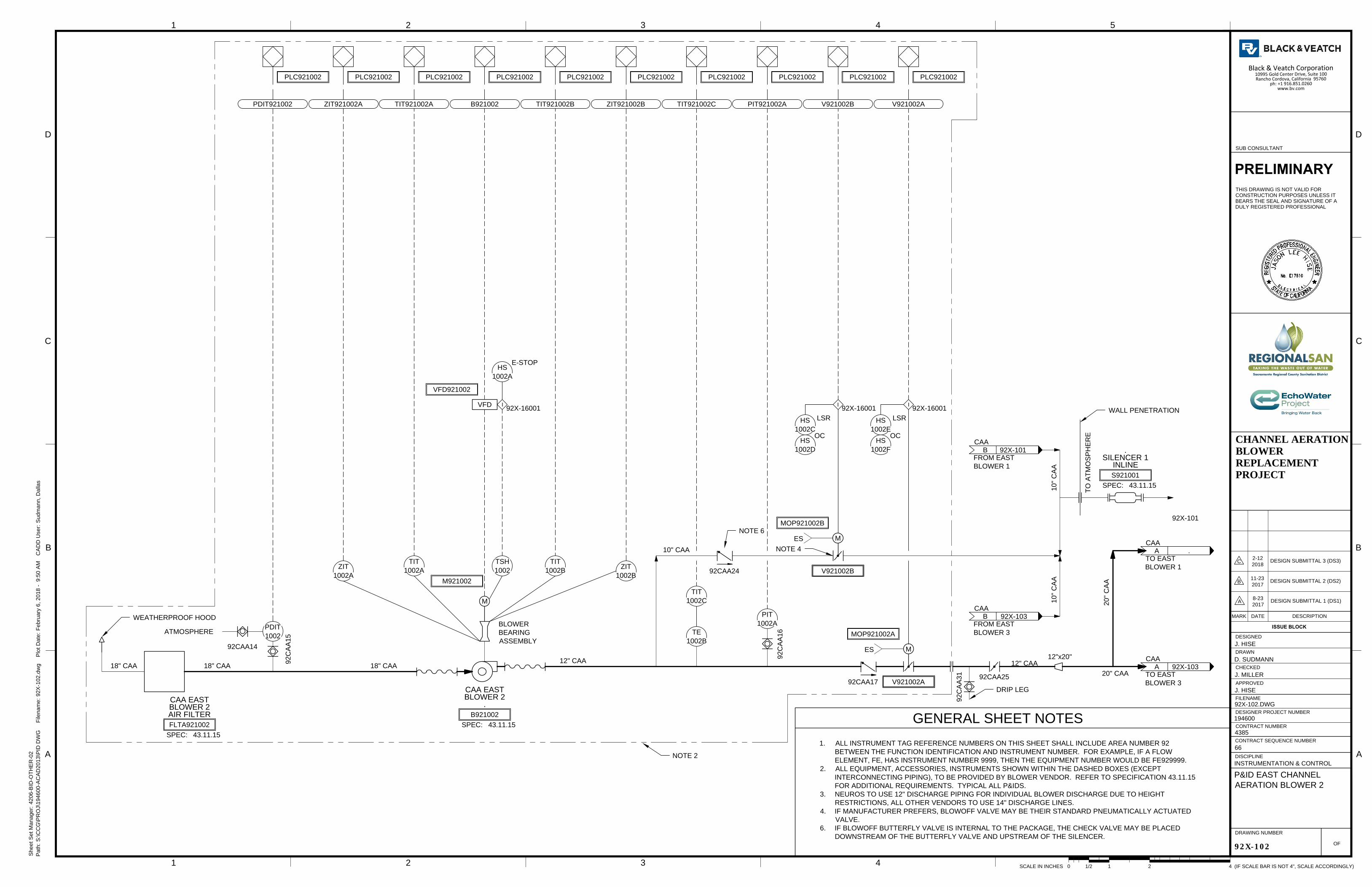
18" CAA 18" CAA
92CAA17
12" CAA
12" CAA
MOP921002B
M
V921002B
SPEC:
S921001
43.11.15
INLINE
SILENCER 1
.
TIT
1002C
92C
AA
16
PIT
1002A
92C
AA
15
92CAA14
I
92X-16001
B921002 V921002A
I
92X-16001
VFD921002
VFD
SPEC:
B921002
43.11.15
.
BLOWER 2
CAA EAST
TIT
1002B
TIT
1002A
ZIT
1002A
ZIT
1002B
TIT921002BTIT921002AZIT921002A
PDIT
1002
TIT921002C PIT921002A V921002B
LSR
HS
1002C
I
92X-16001
OC
HS
1002D
A .
CAA
TO EAST
BLOWER 3
PDIT921002
PLC921002
ZIT921002B
BLOWER
BEARING
ASSEMBLY
ATMOSPHERE
PLC921002 PLC921002 PLC921002 PLC921002 PLC921002 PLC921002 PLC921002 PLC921002 PLC921002
TSH
1002
NOTE 2
LSR
HS
1002E
OC
HS
1002F
TO
A
TM
OS
PH
ER
E
TE
1002B
SPEC:
FLTA921002
43.11.15
AIR FILTER
BLOWER 2
CAA EAST
M921002
M
A .
CAA
TO EAST
BLOWER 1
92X-101
92X-103
WEATHERPROOF HOOD
12"x20"
20" CAA
20" C
AA
18" CAA
10" CAA
10" C
AA
10" C
AA
B .
CAA
FROM EAST
BLOWER 1
B .
CAA
FROM EAST
BLOWER 3
92X-101
92X-103
NOTE 4
WALL PENETRATION
MOP921002A
M
V921002A
E-STOP
HS
1002A
ES
ES
92CAA24
92CAA25
NOTE 6
92C
AA
31
DRIP LEG
1
CHECKED
APPROVED
DRAWN
DESIGNED
2 3 4 5
B
C
D
B
C
D
A
OF
FILENAME
DESIGNER PROJECT NUMBER
CONTRACT NUMBER
DRAWING NUMBER
ISSUE BLOCK
MARK DATE DESCRIPTION
CONTRACT SEQUENCE NUMBER
DISCIPLINE
1 2 3 4
(IF SCALE BAR IS NOT 4", SCALE ACCORDINGLY)SCALE IN INCHES 411/20 2
Path: S
:\C
CG
\P
RO
J\194600-A
CA
D2013\P
ID
D
WG
F
ilenam
e: 92X
-102.dw
g P
lot D
ate: F
ebruary 6, 2018 - 9:50 A
M C
AD
D U
ser: S
udm
ann, D
allas
A
Sheet S
et M
anager: 4206-B
ID
-O
TH
ER
-02
PRELIMINARY
THIS DRAWING IS NOT VALID FOR
CONSTRUCTION PURPOSES UNLESS IT
BEARS THE SEAL AND SIGNATURE OF A
DULY REGISTERED PROFESSIONAL
SUB CONSULTANT
CHANNEL AERATIONBLOWERREPLACEMENTPROJECT
92X-102
P&ID EAST CHANNEL
AERATION BLOWER 2
INSTRUMENTATION & CONTROL
66
4385
194600
92X-102.DWG
J. HISE
J. MILLER
D. SUDMANN
J. HISE
A
8-23
2017
DESIGN SUBMITTAL 1 (DS1)
B
11-23
2017
DESIGN SUBMITTAL 2 (DS2)
C
2-12
2018
DESIGN SUBMITTAL 3 (DS3)
1. ALL INSTRUMENT TAG REFERENCE NUMBERS ON THIS SHEET SHALL INCLUDE AREA NUMBER 92
BETWEEN THE FUNCTION IDENTIFICATION AND INSTRUMENT NUMBER. FOR EXAMPLE, IF A FLOW
ELEMENT, FE, HAS INSTRUMENT NUMBER 9999, THEN THE EQUIPMENT NUMBER WOULD BE FE929999.
2. ALL EQUIPMENT, ACCESSORIES, INSTRUMENTS SHOWN WITHIN THE DASHED BOXES (EXCEPT
INTERCONNECTING PIPING), TO BE PROVIDED BY BLOWER VENDOR. REFER TO SPECIFICATION 43.11.15
FOR ADDITIONAL REQUIREMENTS. TYPICAL ALL P&IDS.
3. NEUROS TO USE 12" DISCHARGE PIPING FOR INDIVIDUAL BLOWER DISCHARGE DUE TO HEIGHT
RESTRICTIONS, ALL OTHER VENDORS TO USE 14" DISCHARGE LINES.
4. IF MANUFACTURER PREFERS, BLOWOFF VALVE MAY BE THEIR STANDARD PNEUMATICALLY ACTUATED
VALVE.
6. IF BLOWOFF BUTTERFLY VALVE IS INTERNAL TO THE PACKAGE, THE CHECK VALVE MAY BE PLACED
DOWNSTREAM OF THE BUTTERFLY VALVE AND UPSTREAM OF THE SILENCER.
GENERAL SHEET NOTES

18" CAA 18" CAA
92CAA21
12" CAA12" CAA
MOP921003B
M
V921003B
TIT
1003C
92C
AA
20
PIT
1003A
92C
AA
19
92CAA18
I
92X-16001
B921003 V921003A
I
92X-16001
VFD921003
VFD
SPEC:
B921003
43.11.15
.
BLOWER 3
CAA EAST
TIT
1003B
TIT
1003A
ZIT
1003A
ZIT
1003B
TIT921003BTIT921003AZIT921003A
PDIT
1003
TIT921003C PIT921003A V921003B
LSR
HS
1003C
I
92X-16001
OC
HS
1003D
.
CAA
TO PRIMARY
EFFLUENT CHANNEL
PDIT921003
PLC921003
ZIT921003B
BLOWER
BEARING
ASSEMBLY
ATMOSPHERE
PLC921003 PLC921003 PLC921003 PLC921003 PLC921003 PLC921003 PLC921003 PLC921003 PLC921003
TSH
1003
NOTE 2
LSR
HS
1003E
OC
HS
1003F
TE
1003B
SPEC:
FLTA921003
43.11.15
AIR FILTER
BLOWER 3
CAA EAST
M921003
M
A .
CAA
FROM EAST
BLOWER 2
92X-102
WEATHERPROOF HOOD
18" CAA
12"x20"
20" CAA
20" C
AA
B .
CAA
TO EAST
BLOWER 2
10" AA
92X-102
39CAA55
20"x12"
NOTE 4
MOP921003A
M
V921003A
PI
0017
39C
AA
63
ES
ES
E-STOP
HS
1003A
NOTE 5
92CAA26
NOTE 6
92CAA27
92C
AA
29
PIT
1003B
PIT921003B
PLC921003
92C
AA
32
DRIP LEG
1
CHECKED
APPROVED
DRAWN
DESIGNED
2 3 4 5
B
C
D
B
C
D
A
OF
FILENAME
DESIGNER PROJECT NUMBER
CONTRACT NUMBER
DRAWING NUMBER
ISSUE BLOCK
MARK DATE DESCRIPTION
CONTRACT SEQUENCE NUMBER
DISCIPLINE
1 2 3 4
(IF SCALE BAR IS NOT 4", SCALE ACCORDINGLY)SCALE IN INCHES 411/20 2
Path: S
:\C
CG
\P
RO
J\194600-A
CA
D2013\P
ID
D
WG
F
ilenam
e: 92X
-103.dw
g P
lot D
ate: F
ebruary 6, 2018 - 9:52 A
M C
AD
D U
ser: S
udm
ann, D
allas
A
Sheet S
et M
anager: 4206-B
ID
-O
TH
ER
-02
PRELIMINARY
THIS DRAWING IS NOT VALID FOR
CONSTRUCTION PURPOSES UNLESS IT
BEARS THE SEAL AND SIGNATURE OF A
DULY REGISTERED PROFESSIONAL
SUB CONSULTANT
CHANNEL AERATIONBLOWERREPLACEMENTPROJECT
92X-103
P&ID EAST CHANNEL
AERATION BLOWER 3
INSTRUMENTATION & CONTROL
66
4385
194600
92X-103.DWG
J. HISE
J. MILLER
D. SUDMANN
J. HISE
A
8-23
2017
DESIGN SUBMITTAL 1 (DS1)
B
11-23
2017
DESIGN SUBMITTAL 2 (DS2)
C
2-12
2018
DESIGN SUBMITTAL 3 (DS3)
GENERAL SHEET NOTES
1. ALL INSTRUMENT TAG REFERENCE NUMBERS ON THIS SHEET SHALL INCLUDE AREA NUMBER 92 BETWEEN THE
FUNCTION IDENTIFICATION AND INSTRUMENT NUMBER UNLESS MODIFIED BY NOTE. FOR EXAMPLE, IF A FLOW
ELEMENT, FE, HAS INSTRUMENT NUMBER 9999, THEN THE EQUIPMENT NUMBER WOULD BE FE929999.
2. ALL EQUIPMENT, ACCESSORIES, INSTRUMENTS SHOWN WITHIN THE DASHED BOXES (EXCEPT INTERCONNECTING
PIPING), TO BE PROVIDED BY BLOWER VENDOR. REFER TO SPECIFICATION 43.11.15 FOR ADDTIONAL
REQUIREMENTS. TYPICAL ALL P&IDS.
3. NEUROS TO USE 12" DISCHARGE PIPING FOR INDIVIDUAL BLOWER DISCHARGE DUE TO HEIGHT RESTRICTIONS, ALL
OTHER VENDORS TO USE 14" DISCHARGE LINES.
4. IF MANUFACTURER PREFERS, BLOWOFF VALVE MAY BE THEIR STANDARD PNEUMATICALLY ACTUATED VALVE.
5. BLOWER IS LOCATED IN AREA 92. INDIVIDUAL HEADERS AND HEADER ISOLATION VALVES ARE LOCATED IN AREA 39.
6. IF BLOWOFF BUTTERFLY VALVE IS INTERNAL TO THE PACKAGE, THE CHECK VALVE MAY BE PLACED DOWNSTREAM
OF THE BUTTERFLY VALVE AND UPSTREAM OF THE SILENCER.

24" CAA 24" CAA
51CAA203
20" CAA20" CAA
SPEC:
S517511B
43.11.15
INLINE
SILENCER 1
.
TIT
7511C
51C
AA
202
PIT
7511A
51C
AA
201
51CAA200
I
51X-16001
B517511 V517511A
I
51X-16001
VFD517511
VFD
SPEC:
B517511
43.11.15
.
BLOWER 1
CAA WEST
TIT
7511B
TIT
7511A
ZIT
7511A
ZIT
7511B
TIT517511BTIT517511AZIT517511A
PDIT
7511
TIT517511C PIT517511A V517511B
LSR
HS
7511C
I
51X-16001
OC
HS
7511D
A .
CAA
TO WEST
BLOWER SHEET 2
PDIT517511
PLC517511
ZIT517511B
BLOWER
BEARING
ASSEMBLY
ATMOSPHERE
PLC517511 PLC517511 PLC517511 PLC517511 PLC517511 PLC517511 PLC517511 PLC517511 PLC517511
TSH
7511
NOTE 2
LSR
HS
7511E
OC
HS
7511F
TO
AT
MO
SP
HE
RE
TE
7511B
SPEC:
FLTA517511
43.11.15
AIR FILTER
BLOWER 1
CAA WEST
M517511
M
51X-102
MOP517511B
M
V517511B
14" CAA
NOTE 3
WALL
PENETRATION
MOP517511A
M
V517511A
ES
ES
E-STOP
HS
7511A
51CAA216
51C
AA
224
DRIP LEG
1
CHECKED
APPROVED
DRAWN
DESIGNED
2 3 4 5
B
C
D
B
C
D
A
OF
FILENAME
DESIGNER PROJECT NUMBER
CONTRACT NUMBER
DRAWING NUMBER
ISSUE BLOCK
MARK DATE DESCRIPTION
CONTRACT SEQUENCE NUMBER
DISCIPLINE
1 2 3 4
(IF SCALE BAR IS NOT 4", SCALE ACCORDINGLY)SCALE IN INCHES 411/20 2
Path: S
:\C
CG
\P
RO
J\194600-A
CA
D2013\P
ID
D
WG
F
ilenam
e: 51X
-101.dw
g P
lot D
ate: F
ebruary 6, 2018 - 9:28 A
M C
AD
D U
ser: S
udm
ann, D
allas
A
Sheet S
et M
anager: 4206-B
ID
-O
TH
ER
-02
PRELIMINARY
THIS DRAWING IS NOT VALID FOR
CONSTRUCTION PURPOSES UNLESS IT
BEARS THE SEAL AND SIGNATURE OF A
DULY REGISTERED PROFESSIONAL
SUB CONSULTANT
CHANNEL AERATIONBLOWERREPLACEMENTPROJECT
51X-101
P&ID WEST CHANNEL
AERATION BLOWER 1
INSTRUMENTATION & CONTROL
66
4385
194600
51X-101.DWG
J. HISE
J. MILLER
D. SUDMANN
J. HISE
A
8-23
2017
DESIGN SUBMITTAL 1 (DS1)
B
11-23
2017
DESIGN SUBMITTAL 2 (DS2)
C
2-12
2018
DESIGN SUBMITTAL 3 (DS3)
1. ALL INSTRUMENT TAG REFERENCE NUMBERS ON THIS SHEET
SHALL INCLUDE AREA NUMBER 51 BETWEEN THE FUNCTION
IDENTIFICATION AND INSTRUMENT NUMBER. FOR EXAMPLE, IF A
FLOW ELEMENT, FE, HAS INSTRUMENT NUMBER 9999, THEN THE
EQUIPMENT NUMBER WOULD BE FE519999.
2. ALL EQUIPMENT, ACCESSORIES, INSTRUMENTS SHOWN WITHIN THE
DASHED BOXES (EXCEPT INTERCONNECTING PIPING), TO BE
PROVIDED BY BLOWER VENDOR. REFER TO SPECIFICATION
43.11.15 FOR ADDITIONAL REQUIREMENTS. TYPICAL ALL P&IDS.
3. IF MANUFACTURER PREFERS, BLOWOFF VALVE MAY BE THEIR
STANDARD PNEUMATICALLY ACTUATED VALVE.
GENERAL SHEET NOTES
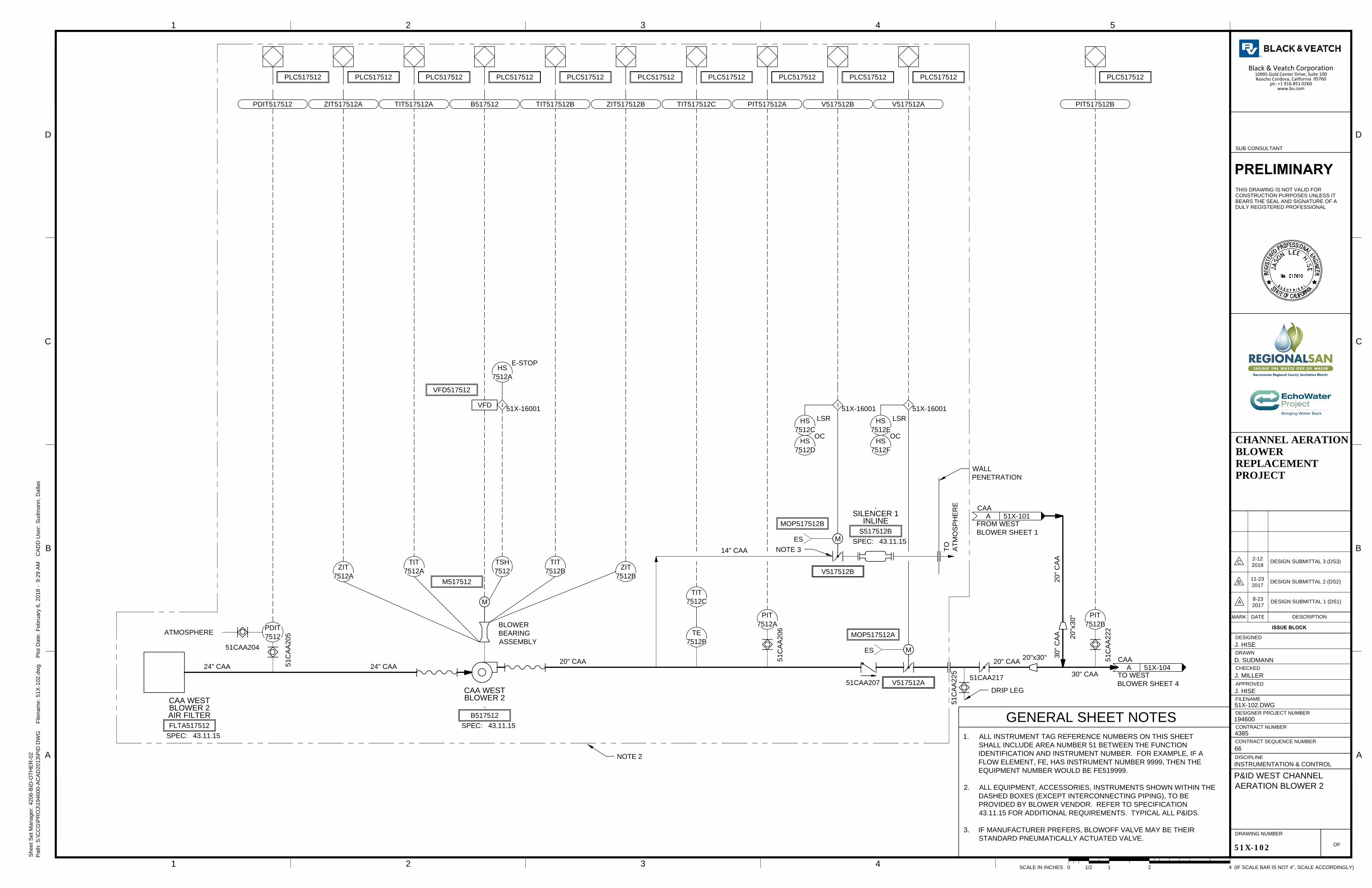
24" CAA 24" CAA
51CAA207
20" CAA20" CAA
SPEC:
S517512B
43.11.15
INLINE
SILENCER 1
.
TIT
7512C
51C
AA
206
PIT
7512A
51C
AA
205
51CAA204
I
51X-16001
B517512 V517512A
I
51X-16001
VFD517512
VFD
SPEC:
B517512
43.11.15
.
BLOWER 2
CAA WEST
TIT
7512B
TIT
7512A
ZIT
7512A
ZIT
7512B
TIT517512BTIT517512AZIT517512A
PDIT
7512
TIT517512C PIT517512A V517512B
LSR
HS
7512C
I
51X-16001
OC
HS
7512D
A .
CAA
TO WEST
BLOWER SHEET 4
PDIT517512
PLC517512
ZIT517512B
BLOWER
BEARING
ASSEMBLY
ATMOSPHERE
PLC517512 PLC517512 PLC517512 PLC517512 PLC517512 PLC517512 PLC517512 PLC517512 PLC517512
TSH
7512
NOTE 2
LSR
HS
7512E
OC
HS
7512F
TO
AT
MO
SP
HE
RE
TE
7512B
SPEC:
FLTA517512
43.11.15
AIR FILTER
BLOWER 2
CAA WEST
M517512
M
A .
CAA
FROM WEST
BLOWER SHEET 1
51X-101
51X-104
MOP517512B
M
V517512B
20"x30"
20"x30"
30" CAA
30" C
AA
20" C
AA
14" CAA
NOTE 3
WALL
PENETRATION
MOP517512A
M
V517512A
E-STOP
HS
7512A
ES
ES
51CAA217
51C
AA
222
PIT
7512B
PIT517512B
PLC517512
51C
AA
225
DRIP LEG
1
CHECKED
APPROVED
DRAWN
DESIGNED
2 3 4 5
B
C
D
B
C
D
A
OF
FILENAME
DESIGNER PROJECT NUMBER
CONTRACT NUMBER
DRAWING NUMBER
ISSUE BLOCK
MARK DATE DESCRIPTION
CONTRACT SEQUENCE NUMBER
DISCIPLINE
1 2 3 4
(IF SCALE BAR IS NOT 4", SCALE ACCORDINGLY)SCALE IN INCHES 411/20 2
Path: S
:\C
CG
\P
RO
J\194600-A
CA
D2013\P
ID
D
WG
F
ilenam
e: 51X
-102.dw
g P
lot D
ate: F
ebruary 6, 2018 - 9:29 A
M C
AD
D U
ser: S
udm
ann, D
allas
A
Sheet S
et M
anager: 4206-B
ID
-O
TH
ER
-02
PRELIMINARY
THIS DRAWING IS NOT VALID FOR
CONSTRUCTION PURPOSES UNLESS IT
BEARS THE SEAL AND SIGNATURE OF A
DULY REGISTERED PROFESSIONAL
SUB CONSULTANT
CHANNEL AERATIONBLOWERREPLACEMENTPROJECT
51X-102
P&ID WEST CHANNEL
AERATION BLOWER 2
INSTRUMENTATION & CONTROL
66
4385
194600
51X-102.DWG
J. HISE
J. MILLER
D. SUDMANN
J. HISE
A
8-23
2017
DESIGN SUBMITTAL 1 (DS1)
B
11-23
2017
DESIGN SUBMITTAL 2 (DS2)
C
2-12
2018
DESIGN SUBMITTAL 3 (DS3)
1. ALL INSTRUMENT TAG REFERENCE NUMBERS ON THIS SHEET
SHALL INCLUDE AREA NUMBER 51 BETWEEN THE FUNCTION
IDENTIFICATION AND INSTRUMENT NUMBER. FOR EXAMPLE, IF A
FLOW ELEMENT, FE, HAS INSTRUMENT NUMBER 9999, THEN THE
EQUIPMENT NUMBER WOULD BE FE519999.
2. ALL EQUIPMENT, ACCESSORIES, INSTRUMENTS SHOWN WITHIN THE
DASHED BOXES (EXCEPT INTERCONNECTING PIPING), TO BE
PROVIDED BY BLOWER VENDOR. REFER TO SPECIFICATION
43.11.15 FOR ADDITIONAL REQUIREMENTS. TYPICAL ALL P&IDS.
3. IF MANUFACTURER PREFERS, BLOWOFF VALVE MAY BE THEIR
STANDARD PNEUMATICALLY ACTUATED VALVE.
GENERAL SHEET NOTES

24" CAA 24" CAA
51CAA211
20" CAA20" CAA
SPEC:
S517513B
43.11.15
INLINE
SILENCER 1
.
TIT
7513C
51C
AA
210
PIT
7513A
51C
AA
209
51CAA208
I
51X-16001
B517513 V517513A
I
51X-16001
VFD517513
VFD
SPEC:
B517513
43.11.15
.
BLOWER 3
CAA WEST
TIT
7513B
TIT
7513A
ZIT
7513A
ZIT
7513B
TIT517513BTIT517513AZIT517513A
PDIT
7513
TIT517513C PIT517513A V517513B
LSR
HS
7513C
I
51X-16001
OC
HS
7513D
A .
CAA
TO WEST
BLOWER SHEET 4
PDIT517513
PLC517513
ZIT517513B
BLOWER
BEARING
ASSEMBLY
ATMOSPHERE
PLC517513 PLC517513 PLC517513 PLC517513 PLC517513 PLC517513 PLC517513 PLC517513 PLC517513
TSH
7513
NOTE 2
LSR
HS
7513E
OC
HS
7513F
TO
AT
MO
SP
HE
RE
TE
7513B
SPEC:
FLTA517513
43.11.15
AIR FILTER
BLOWER 3
CAA WEST
M517513
M
51X-104
MOP517513B
M
V517513B
14" CAA
NOTE 3
WALL PENETRATION
MOP517513A
M
V517513A
E-STOP
HS
7513A
ES
ES
51CAA218
51C
AA
226
DRIP LEG
1
CHECKED
APPROVED
DRAWN
DESIGNED
2 3 4 5
B
C
D
B
C
D
A
OF
FILENAME
DESIGNER PROJECT NUMBER
CONTRACT NUMBER
DRAWING NUMBER
ISSUE BLOCK
MARK DATE DESCRIPTION
CONTRACT SEQUENCE NUMBER
DISCIPLINE
1 2 3 4
(IF SCALE BAR IS NOT 4", SCALE ACCORDINGLY)SCALE IN INCHES 411/20 2
Path: S
:\C
CG
\P
RO
J\194600-A
CA
D2013\P
ID
D
WG
F
ilenam
e: 51X
-103.dw
g P
lot D
ate: F
ebruary 6, 2018 - 9:30 A
M C
AD
D U
ser: S
udm
ann, D
allas
A
Sheet S
et M
anager: 4206-B
ID
-O
TH
ER
-02
PRELIMINARY
THIS DRAWING IS NOT VALID FOR
CONSTRUCTION PURPOSES UNLESS IT
BEARS THE SEAL AND SIGNATURE OF A
DULY REGISTERED PROFESSIONAL
SUB CONSULTANT
CHANNEL AERATIONBLOWERREPLACEMENTPROJECT
51X-103
P&ID WEST CHANNEL
AERATION BLOWER 3
INSTRUMENTATION & CONTROL
66
4385
194600
51X-103.DWG
J. HISE
J. MILLER
D. SUDMANN
J. HISE
A
8-23
2017
DESIGN SUBMITTAL 1 (DS1)
B
11-23
2017
DESIGN SUBMITTAL 2 (DS2)
C
2-12
2018
DESIGN SUBMITTAL 3 (DS3)
1. ALL INSTRUMENT TAG REFERENCE NUMBERS ON THIS SHEET
SHALL INCLUDE AREA NUMBER 51 BETWEEN THE FUNCTION
IDENTIFICATION AND INSTRUMENT NUMBER. FOR EXAMPLE, IF A
FLOW ELEMENT, FE, HAS INSTRUMENT NUMBER 9999, THEN THE
EQUIPMENT NUMBER WOULD BE FE519999.
2. ALL EQUIPMENT, ACCESSORIES, INSTRUMENTS SHOWN WITHIN THE
DASHED BOXES (EXCEPT INTERCONNECTING PIPING), TO BE
PROVIDED BY BLOWER VENDOR. REFER TO SPECIFICATION
43.11.15 FOR ADDITIONAL REQUIREMENTS. TYPICAL ALL P&IDS.
3. IF MANUFACTURER PREFERS, BLOWOFF VALVE MAY BE THEIR
STANDARD PNEUMATICALLY ACTUATED VALVE.
GENERAL SHEET NOTES

24" CAA 24" CAA
51CAA215
20" CAA20" CAA
SPEC:
S517514B
43.11.15
INLINE
SILENCER 1
.
TIT
7514C
51C
AA
214
PIT
7514A
51C
AA
213
51CAA212
I
51X-16001
B517514 V517514A
I
51X-16001
VFD517514
VFD
SPEC:
B517514
43.11.15
.
BLOWER 4
CAA WEST
TIT
7514B
TIT
7514A
ZIT
7514A
ZIT
7514B
TIT517514BTIT517514AZIT517514A
PDIT
7514
TIT517514C PIT517514A V517514B
LSR
HS
7514C
I
51X-16001
OC
HS
7514D
. .
CAA
TO SOUTH ML
CHANNEL AND SST
BATTERIES I & II
PDIT517514
PLC517514
ZIT517514B
BLOWER
BEARING
ASSEMBLY
ATMOSPHERE
PLC517514 PLC517514 PLC517514 PLC517514 PLC517514 PLC517514 PLC517514 PLC517514 PLC517514
TSH
7514
NOTE 2
LSR
HS
7514E
OC
HS
7514F
TO
AT
MO
SP
HE
RE
TE
7514B
SPEC:
FLTA517514
43.11.15
AIR FILTER
BLOWER 4
CAA WEST
M517514
M
A .
.
FROM WEST
BLOWER SHEET 3
51X-103
MOP517514B
M
V517514B
A .
.
FROM WEST
BLOWER SHEET 2
20"x30"
20"x30"
30" CAA
30" C
AA
20" C
AA
. .
CAA
TO WEST ML
CHANNEL, SOUTH ML
CHANNEL AND
SST BATTERY III
42CAA128
NEW EXISTING
42CAA127
51X-102
30" C
AA
14" CAA
NOTE 3
WALL PENETRATION
30"x20"
20" C
AA
30"x24"
24" CAA
MOP517514A
M
V517514A
E-STOP
HS
7514A
ES
ES
PI
0009
PI
0010
42C
AA
130
42C
AA
131
NOTE 4
NOTE 4
20"x30"
51CAA219
51C
AA
223
PIT
7514B
PIT517514B
PLC517514
51C
AA
227
DRIP LEG
1
CHECKED
APPROVED
DRAWN
DESIGNED
2 3 4 5
B
C
D
B
C
D
A
OF
FILENAME
DESIGNER PROJECT NUMBER
CONTRACT NUMBER
DRAWING NUMBER
ISSUE BLOCK
MARK DATE DESCRIPTION
CONTRACT SEQUENCE NUMBER
DISCIPLINE
1 2 3 4
(IF SCALE BAR IS NOT 4", SCALE ACCORDINGLY)SCALE IN INCHES 411/20 2
Path: S
:\C
CG
\P
RO
J\194600-A
CA
D2013\P
ID
D
WG
F
ilenam
e: 51X
-104.dw
g P
lot D
ate: F
ebruary 6, 2018 - 9:31 A
M C
AD
D U
ser: S
udm
ann, D
allas
A
Sheet S
et M
anager: 4206-B
ID
-O
TH
ER
-02
PRELIMINARY
THIS DRAWING IS NOT VALID FOR
CONSTRUCTION PURPOSES UNLESS IT
BEARS THE SEAL AND SIGNATURE OF A
DULY REGISTERED PROFESSIONAL
SUB CONSULTANT
CHANNEL AERATIONBLOWERREPLACEMENTPROJECT
51X-104
P&ID WEST CHANNEL
AERATION BLOWER 4
INSTRUMENTATION & CONTROL
66
4385
194600
51X-104.DWG
J. HISE
J. MILLER
D. SUDMANN
J. HISE
A
8-23
2017
DESIGN SUBMITTAL 1 (DS1)
B
11-23
2017
DESIGN SUBMITTAL 2 (DS2)
C
2-12
2018
DESIGN SUBMITTAL 3 (DS3)
1. ALL INSTRUMENT TAG REFERENCE NUMBERS ON THIS SHEET
SHALL INCLUDE AREA NUMBER 51 BETWEEN THE FUNCTION
IDENTIFICATION AND INSTRUMENT NUMBER. FOR EXAMPLE, IF A
FLOW ELEMENT, FE, HAS INSTRUMENT NUMBER 9999, THEN THE
EQUIPMENT NUMBER WOULD BE FE519999.
2. ALL EQUIPMENT, ACCESSORIES, INSTRUMENTS SHOWN WITHIN THE
DASHED BOXES (EXCEPT INTERCONNECTING PIPING), TO BE
PROVIDED BY BLOWER VENDOR. REFER TO SPECIFICATION
43.11.15 FOR ADDITIONAL REQUIREMENTS. TYPICAL ALL P&IDS.
3. IF MANUFACTURER PREFERS, BLOWOFF VALVE MAY BE THEIR
STANDARD PNEUMATICALLY ACTUATED VALVE.
4. INSTRUMENT AREA NUMBER IS 42.
GENERAL SHEET NOTES