CONSTRUCTION OF MAIN COMPONENTS 1.MG1 and MG2
17
TH THS II (TOYOTA HYBRID SYSTEM II) 02HCH31Y MG2 Stator MG1 Rotor Hybrid Transaxle TH-19 J CONSTRUCTION OF MAIN COMPONENTS 1. MG1 and MG2 General D Serving as the source of supplemental motive force that provides power assistance to the engine as needed, the electric motor helps the vehicle achieve excellent dynamic performance, including smooth start-offs and acceleration. When the regenerative brake is activated, MG2 (Motor Generator No.2) converts the vehicle’s kinetic energy into electrical energy, which is then stored in the HV battery. D MG1 (Motor Generator No.1) recharges the HV battery and supplies electrical power to drive MG2. In addition, by regulating the amount of electrical power generated (thus varying the generator’s rpm), MG1 effectively controls the continuously variable transmission function of the transaxle. MG1 also serves as the starter to start the engine. D Both the MG1 and MG2 are compact, lightweight, and highly efficient alternating current permanent magnet synchronous type. D Both the MG1 and MG2 use a rotor containing a V-shaped, high-magnetic force permanent magnet that maximizes the generation of reduction torque. They use a stator made of a low core-loss electromagnetic steel sheet and a high voltage resistant winding wire. Through these measures, the MG1 and MG2 have realized high output and torque in a compact construction. D A cooling system via water pump for the MG1 and MG2 has been added. For details, refer to the cooling system (for Inverter, MG1 and MG2) on page TH-27.
Transcript of CONSTRUCTION OF MAIN COMPONENTS 1.MG1 and MG2

TH
THS II (TOYOTA HYBRID SYSTEM II)
02HCH31Y
MG2 Stator MG1
Rotor
Hybrid Transaxle
TH-19
�CONSTRUCTION OF MAIN COMPONENTS
1. MG1 and MG2
General
� Serving as the source of supplemental motive force that provides power assistance to the engine asneeded, the electric motor helps the vehicle achieve excellent dynamic performance, including smoothstart-offs and acceleration. When the regenerative brake is activated, MG2 (Motor Generator No.2)converts the vehicle’s kinetic energy into electrical energy, which is then stored in the HV battery.
� MG1 (Motor Generator No.1) recharges the HV battery and supplies electrical power to drive MG2. Inaddition, by regulating the amount of electrical power generated (thus varying the generator’s rpm), MG1effectively controls the continuously variable transmission function of the transaxle. MG1 also servesas the starter to start the engine.
� Both the MG1 and MG2 are compact, lightweight, and highly efficient alternating current permanentmagnet synchronous type.
� Both the MG1 and MG2 use a rotor containing a V-shaped, high-magnetic force permanent magnet thatmaximizes the generation of reduction torque. They use a stator made of a low core-loss electromagneticsteel sheet and a high voltage resistant winding wire. Through these measures, the MG1 and MG2 haverealized high output and torque in a compact construction.
� A cooling system via water pump for the MG1 and MG2 has been added. For details, refer to the coolingsystem (for Inverter, MG1 and MG2) on page TH-27.
THS II (TOYOTA HYBRID SYSTEM II)
02HTH22Y
MG1W
U V
MG2W
U V
IPM for MG1and MG2
CurrentSensor
CurrentSensor
Power Transistor
Inverter
TH-20
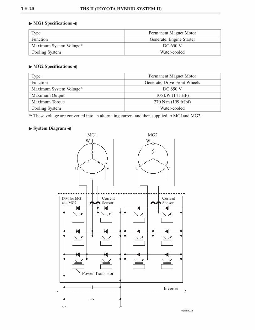
� MG1 Specifications �
Type Permanent Magnet Motor
Function Generate, Engine Starter
Maximum System Voltage* DC 650 V
Cooling System Water-cooled
� MG2 Specifications �
Type Permanent Magnet Motor
Function Generate, Drive Front Wheels
Maximum System Voltage* DC 650 V
Maximum Output 105 kW (141 HP)
Maximum Torque 270 N.m (199 ft.lbf)
Cooling System Water-cooled
*: These voltage are converted into an alternating current and then supplied to MG1and MG2.
� System Diagram �

TH
THS II (TOYOTA HYBRID SYSTEM II)
182TH29
U Phase
RotationalMagnetic Field
#
V Phase
Attraction
#
W Phase
Repulsion
Rotor
Stator Coil
#
N
S
� : From inverter# : Connected internally in the motor
277TH47
(+)
(–)
U V W
Three-phase Alternating Current Output Waveforms
TH-21
Permanent Magnet Motor (for MG1 and MG2)
� When a three-phase alternating current is passed through the three-phase windings of the stator coil, arotational magnetic field is created in the electric motor. By controlling this rotating magnetic fieldaccording to the rotor’s rotational position and speed, the permanent magnets that are provided in therotor become attracted by the rotating magnetic field, thus generating torque.The generated torque is for all practical purposes proportionate to the amount of current, and therotational speed is controlled by the frequency of the alternating current.Furthermore, a high level of torque, all the way to high speeds, can be generated efficiently by properlycontrolling the rotating magnetic field and the angles of the rotor magnets.
� When the motor generates electricity, the rotor rotates to create a magnetic field, which creates a currentin the stator coil.

THS II (TOYOTA HYBRID SYSTEM II)
277TH104
Speed Sensor (Resolver)
ExcitationCoil A
Stator
Rotor
DetectionCoil S
DetectionCoil C
TH-22
Speed Sensor/Resolver (for MG1 and MG2)
� This is an extremely reliable and compact sensor that precisely detects the magnetic pole position, whichis indispensable for ensuring the efficient control of MG1 and MG2.
� The stator of the sensor contains three types of coils: excitation coil A, detection coil S, and detectioncoil C. The detection coils S and C are electrically staggered 90 degrees.The rotor is oval, the distance of the gap between the stator and the rotor varies with the rotation of therotor.
� The flow of an alternating current into an excitation coil A results in the output of signals of a constantfrequency. Coil S and coil C output values that correspond to the position of the rotor. Therefore, the MGECU detects the absolute position based on the difference between the coil S and coil C output values.Furthermore, the MG ECU calculates the rotational speed based on the amount of change in the positionwithin a given length of time.

TH
THS II (TOYOTA HYBRID SYSTEM II)
277TH105
(+)
ExcitationCoil A
(–)
(+)
DetectionCoil S
(–)
Virtual Waveform
(+)
DetectionCoil C
(–)
Virtual Waveform
0� 180�
TH-23
� Because an alternating current flows from this resolver to the excitation coil at a constant frequency, aconstant frequency is output to the coils S and C, regardless of the rotor speed. The rotor is oval, and thedistance of the gap between the stator and the rotor varies with the rotation of the rotor. Consequently,the peak values of the waveforms output by the coils S and C vary in accordance with the position of therotor.
� The MG ECU constantly monitors these peak values, and connects them to form a virtual waveform. TheMG ECU calculates the absolute position of the rotor from the difference between the values of the coilsS and C. It determines the rotor direction based on the difference between the phases of the virtualwaveform of the coil S and the virtual waveform of the coil C. Furthermore, the MG ECU calculates therotational speed based on the amount of change in the rotor position within a given length of time.
� The diagrams below illustrate the waveforms that are output at coils A, S, and C when the rotor makesa positive rotation of 180� from a certain position.

THS II (TOYOTA HYBRID SYSTEM II)
02HTH23Y
Inverter Assembly (Included Inverter, Boost Convert and MG ECU)
Circuit Breaker Sensor (for Front)
TH-24
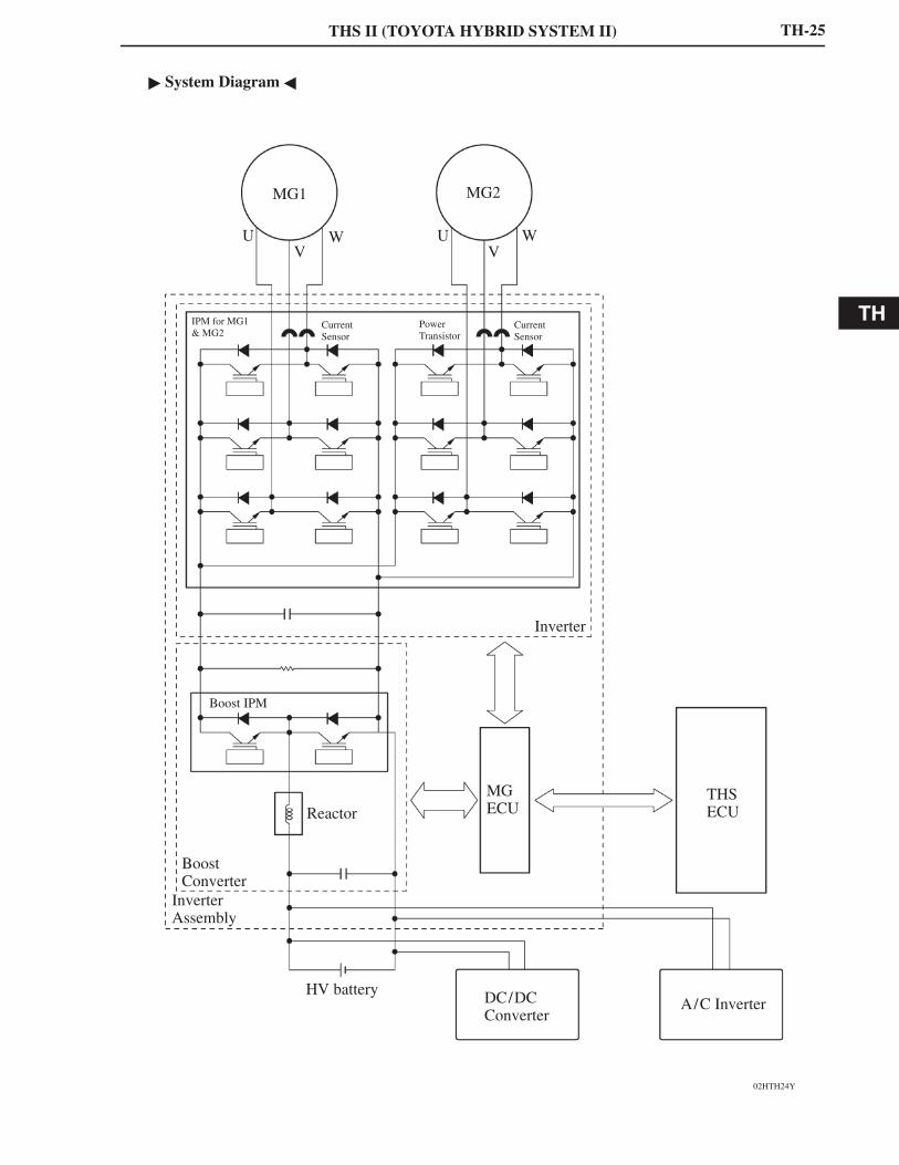
2. Inverter Assembly
General
� The inverter converts the high-voltage direct current of the HV battery into three-phase alternatingcurrent for driving MG1 and MG2.
� The activation of the power transistors is controlled by the THS ECU, via the MG ECU. In addition, theinverter transmits information that is needed for current control, such as the output amperage or voltage,to the THS ECU via the MG ECU.
� Together with MG1 and MG2, the inverter is cooled by the dedicated radiator of the coolant system thatis separate from that of the engine.
� In the event of a collision involving the vehicle, the circuit breaker sensor, which is installed on theinverter, detects a collision signal in order to stop the system. For details, refer to During CollisionControl on page TH-54.
� A boost converter is used in the inverter assembly, in order to boost the nominal voltage output by theHV battery from DC 244.8 V to maximum voltage of DC 650 V. After the voltage is boosted, the inverterconverts the direct current into an alternating current.
� Each of the bridge circuits for MG1 and MG2 contains 6 power transistors. In addition, a signalprocessor/protective function processor has been integrated into a compact IPM (Intelligent PowerModule) for driving the vehicle.
For details on the multiple functions of the inverter, refer to Inverter Assembly Control on page TH-49.
TH
THS II (TOYOTA HYBRID SYSTEM II)
02HTH24Y
MG1
UV
W
MG2
UV
W
IPM for MG1 & MG2
CurrentSensor
PowerTransistor
CurrentSensor
Inverter
Boost IPM
BoostConverter
InverterAssembly
Reactor
HV battery
MGECU
DC/DC Converter
THSECU
A/C Inverter
TH-25
� System Diagram �

THS II (TOYOTA HYBRID SYSTEM II)
02HTH45Y
MG1
Inverter
BoostConverter
Boost IPM
IGBT IGBT
Reactor
HV Battery
TH-26
Boost Converter
� This boost converter boosts the nominal voltage of DC 244.8 V that is output by the HV battery to themaximum voltage of DC 650 V. The converter consists of the boost IPM (Intelligent Power Module) witha built-in IGBT (Insulated Gate Bipolar Transistor) which performs the switching control, and the reactorwhich stores energy. By using these components, the converter boosts the voltage. For details, refer toInverter Assembly Control on page TH-49.
� When MG1 and MG2 acts as the generator, the inverter converts the alternating current into themaximum voltage of DC 650 V, and then the boost converter reduces the voltage to the nominal voltageof DC 244.8 V, thus the HV battery is charged.
� System Diagram �

TH
THS II (TOYOTA HYBRID SYSTEM II)
02HTH26TE
Reservoir Tank
Water Pump
DedicatedRadiator
TH-27
MG (Motor Generator) ECU
� The MG ECU is provided in the inverter assembly. In accordance with the signals received from the THSECU, the MG ECU controls the inverter and boost converter in order to drive MG1 or MG2 or cause themto generate electricity.
� The MG ECU transmits information that is required for vehicle control, such as the inverter outputamperage, inverter temperature, and any failure information, to the THS ECU. It receives informationthat is required for controlling the motor generator, such as the required motive force and the motortemperature, from the THS ECU.
3. Cooling System (for Inverter, MG1 and MG2)
� A cooling system that is independent from the engine cooling system has been provided to cool theinverter, MG1 and MG2.
� This cooling system activates when the power supply status is switched to the READY ON state.
� A radiator, which is exclusively used for the inverter, MG1 and MG2, has been provided above thecondenser (for the A/C). By integrating the independent inverter radiator, A/C condenser and engineradiator, the layout has been made more compact.
� Specifications �
Water Pump Discharge Volume liter /min. 10 or above (65�C (149�F))
Capacity liters (US qts, Imp. qts) 2.9 (3.1, 2.6)
TypeTOYOTA Genuine Super Long Life
Coolant
Typep g
Coolant (SLLC) or the equivalent*Coolant
Color Pink
Maintenance First Time 100,000 miles (160,000 km)
Intervals Subsequent Every 50,000 miles (80,000 km)
*: Similar high quality ethylene glycol based non-silicate, non-amine, non-nitrite, and non-borate coolantwith long-life hybrid organic acid technology. (Coolant with hybrid organic acid technology consists ofa combination of low phosphates and organic acids.)
� SLLC is pre-mixed (50% coolant and 50% deionized water for U.S.A. or 55% coolant and 45% deionizedwater for Canada), so no dilution is needed when adding or replacing SLLC in the vehicle.

THS II (TOYOTA HYBRID SYSTEM II)
02HTH27TE
Rear SeatIntake Duct
Cooling Fan
HV Battery Unit
Exhaust Duct
TH-28
4. HV Battery
General
� The ’07 Camry Hybrid model uses sealed nickel metal hydride (Ni-MH) HV batteries. The HV batterieshave a high power density, are lightweight and offer longevity to match the characteristics of the THSII. Because the THS II effects charge/discharge control to maintain the HV batteries at a constant SOC(state of charge) level while the vehicle is operating normally, it does not need to be recharged externally.
� The HV batteries use nickel-plated, metal container type cells to realize enhanced cooling performanceand a compact construction. As a result, high power density, lightweight construction, and longevity havebeen accomplished at high levels.
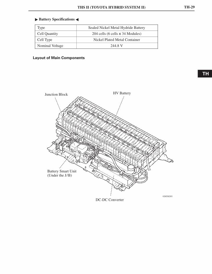
� The HV battery unit consists of 34 separate batteries. The batteries each comprise 6 cells and they areconnected to each other in series through a bus bar module. The cells of the batteries are connected attwo locations in order to reduce the internal resistance and improve efficiency. The HV battery unit,which has a total of 204 cells (6 cells x 34 batteries) and a nominal voltage of 244.8 V (1.2 V x 204 cells),is located in the luggage compartment behind the rear seat.
� A junction block, battery smart unit and DC/DC converter are used. Integrated into the junction blockare an SMRG (System Main Relay Ground), SMRB (System Main Relay Battery) and a current sensor.The battery smart unit monitors the HV battery. The DC/DC converter supplies power to the auxiliarybattery after decreasing the nominal voltage of DC 244.8 V supplied by the HV battery to DC 12 V. Powerto the lights, audio system, air conditioning system (except the electric inverter compressor) and ECUsis supplied by the auxiliary battery.The battery smart unit, junction block, and DC/DC converter are located in the battery front side carrier,which is in the same housing as the HV battery unit. This realizes a compact package.
� An air-cooling method, which uses a dedicated cooling fan to cool the HV battery with air from insidethe cabin, is employed. A dedicated cooling fan is also provided for the DC/DC converter. Thus, highlyefficient air-cooling has been achieved.
� A service plug that shuts off the circuit is provided in the middle of the HV battery modules (betweenNo.18 and No.19 batteries). Before servicing any portion of the high-voltage circuit, be sure to removethe service plug.
TH
THS II (TOYOTA HYBRID SYSTEM II)
02HTH28Y
HV BatteryJunction Block
Battery Smart Unit(Under the J/B)
DC-DC Converter
TH-29
� Battery Specifications �
Type Sealed Nickel Metal Hydride Battery
Cell Quantity 204 cells (6 cells x 34 Modules)
Cell Type Nickel Plated Metal Container
Nominal Voltage 244.8 V
Layout of Main Components

THS II (TOYOTA HYBRID SYSTEM II)
02HTH29Y
HV Battery Unit
HVBattery DC/DC Converter
SMRP
BatterySmart Unit
IDH+DT
SMRPVLO
NODD
GND
THS ECU
AuxiliaryBattery
DC/DCAMD
IGCT
IGCTRelay
02HTH30Y
SMRG
SMRB
Junction Block
TH-30
DC/DC Converter
The power source for auxiliary equipment of the vehicle such as the lights, audio system, and the airconditioning system (except electric inverter compressor), as well as the ECUs, is based on a DC 12 Vsystem. Because the THS II generator outputs at nominal voltage of DC 244.8 V, the converter is used totransform the voltage from DC 244.8 V to DC 12 V in order to recharge the auxiliary battery.
� System Diagram �
Junction Block
A junction block, in which an SMRG and SMRB are integrated, is used.

TH
THS II (TOYOTA HYBRID SYSTEM II)
02HTH31Y
Service Plug
Glove
Service Tip
After the service, please do not start the system until the service plug is connected.The battery smart unit may break down.
TH-31
Service Plug
By removing the service plug before performing any inspection or service, the high-voltage circuit is shutoff at the intermediate position of the HV battery, thus ensuring safety during service.The service plug assembly contains a reed switch for interlock. Lifting the clip lock up turns OFF the leadswitch, which shuts off the SMR. However, to ensure safety, make sure to turn OFF the ignition switchbefore removing the service plug. The main fuse for the high-voltage circuit is provided inside of the service plug assembly.For further details on how to handle the service plug and other safety cautions, refer to the 2007 CamryHybrid Vehicle Repair Manual (Pub. No. RM02H0U).

THS II (TOYOTA HYBRID SYSTEM II)
02HTH32TE
The Flow of Air
Intake Duct
Cooling Fan
Exhaust Duct
The Flow of Air
Cooling Fan
HV Battery Module
Rear View Cross Section
TH-32
HV Battery and DC/DC Converter Cooling System
1) HV Battery Cooling System
� A dedicated cooling system is used to ensure that the HV battery performs properly, despite itgenerating significant heat during the repetitive charge and discharge cycles.This cooling system employs an air-cooling method, which uses the dedicated cooling fan to cool theHV battery with air from inside the cabin.
� The air from inside the cabin, which is introduced through the intake duct located on the rear packagetray trim, flows downwards through the battery module, reducing the temperature of the batterymodule, and is emitted from the vehicle through the exhaust duct.
� The THS ECU controls the operation of the cooling fan for the HV battery. The THS ECU receivesthe signals from the battery temperature sensor, which is built into the HV battery, via the battery smartunit. Then, it controls the cooling fan in order to control the battery module temperature appropriately.For details, refer to THS ECU Control on page TH-40.
� HV Battery Cooling Fan Specifications �
Fan Type Sirocco Fan
Motor Type DC Motor (without Brush)

TH
THS II (TOYOTA HYBRID SYSTEM II)
02HTH21TE
The Flow of Air
Cooling Fan (for DC/DC Converter)
DC/DC Converter
TH-33
2) DC/DC Converter Cooling System
As with as the HV battery cooling system, the DC/DC converter cooling system uses a dedicated coolingfan to cool the converter. Air from inside the cabin is introduced through the intake duct located on therear package tray trim. In addition, the converter itself is equipped with cooling fins. Thus, excellentair-cooling performance is achieved.
� DC/DC Converter Cooling Fan Specifications �
Type Sirocco Fan
Motor Type DC Motor (without Brush)

THS II (TOYOTA HYBRID SYSTEM II)
228TU23
Hall IC
Magnetic Yoke
Accelerator Pedal Arm
228TU25
Accelerator Pedal Position Sensor
Magnet
HallIC
HallIC
Magnet
VPA
EP1
VCP1
VPA2
EP2
VCP2
THSECU
V
5
OutputVoltage
0
FullyClose
VPA2
VPA
FullyOpen
Accelerator Pedal Depressed Angle
228TU24
Service Tip
The inspection method differs from the conventional accelerator pedal position sensor because thissensor uses a hall IC. For details, refer to the 2007 Camry Hybrid Vehicle Repair Manual (Pub. No.RM02H0U).
TH-34
5. Accelerator Pedal Position Sensor
The magnetic yoke that is mounted at the base of the accelerator pedal arm rotates around the Hall IC inaccordance with the amount of effort that is applied to the accelerator pedal. The Hall IC converts the changesin the magnetic flux that occur at that time into electrical signals, and outputs them in the form of acceleratorpedal effort to the THS ECU.
TH
THS II (TOYOTA HYBRID SYSTEM II)
02HTH33Y
Electric Inverter Compressor Engine
JunctionBlock Service Plug
HV BatteryDC/DC ConverterHybridTransaxle
InverterAssembly
TH-35
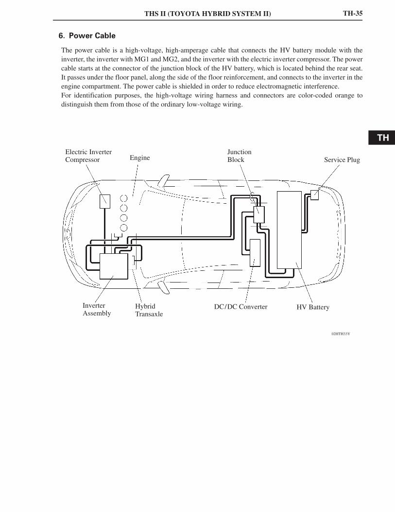
6. Power Cable
The power cable is a high-voltage, high-amperage cable that connects the HV battery module with theinverter, the inverter with MG1 and MG2, and the inverter with the electric inverter compressor. The powercable starts at the connector of the junction block of the HV battery, which is located behind the rear seat.It passes under the floor panel, along the side of the floor reinforcement, and connects to the inverter in theengine compartment. The power cable is shielded in order to reduce electromagnetic interference.For identification purposes, the high-voltage wiring harness and connectors are color-coded orange todistinguish them from those of the ordinary low-voltage wiring.