9211 rev Y - Cooper Industries · Document 9211 Rev. Y Instruction Manual Airside Guidance Sign...
44
Document 9211 Revision Y April 10, 2012 Instruction Manual Airside Guidance Sign Series 858XX-X Sizes 1, 2, 3, and 5 62 Watt Lamp Cooper Industries Crouse-Hinds Division Crouse-Hinds Airport Lighting 1200 Kennedy Road Windsor, CT 06095 Copyright © 2012 Cooper Technologies Company For Parts or Technical Service Call (860) 683-4300
Transcript of 9211 rev Y - Cooper Industries · Document 9211 Rev. Y Instruction Manual Airside Guidance Sign...

Document 9211
Revision Y
April 10, 2012
Instruction Manual
Airside Guidance Sign
Series 858XX-X
Sizes 1, 2, 3, and 5
62 Watt Lamp
Cooper Industries
Crouse-Hinds Division
Crouse-Hinds Airport
Lighting
1200 Kennedy Road
Windsor, CT 06095
Copyright © 2012 Cooper Technologies Company
For Parts or Technical Service Call (860) 683-4300

Document 9211
Rev. Y Instruction Manual
Airside Guidance Sign
Series 858XX-X
Sizes 1, 2, 3, and 5
ii
Revisions
Revision
Number
Issue/Reissue
Letter
Number Description Checked Approved
T A203-281A See Record Copy for Previous Revisions.
Revised extensively to delete use of 60880-X
P.C. Board and related data. Added 61153-1
P.C. Board and related data
1/21/04 GFR
U A204-291 Removed all references to LED Lamp out
Indicator P/N 61158 and its operation.
Incorporated Option 13 (tethers) as standard
equipment. Added Options 19 and 20 to 1.3
Part Number and deleted Options 13 & 14.
Added Symptom 5 to Table 1. Added Para
4.5 and Figure 10A.
1/10/05 GFR
V A205-056 Added instructions and info to Para. 4.5
8/30/05 GFR
W A208-004 Added copyright to cover page; Figure 21,
deleted alternate method (used Rawl 7324 or
equal)
1/23/08 PG
X A208-243 Updated Table 6 and Table 7; Updated
Figures 1 thru 7 to reflect changes in Table 6
and Table 7.
11/7/08 AJ
Y A212-165 Page 12, Item 24 was 62241-1 thru 62241-3 5/10/12 MCB

Document 9211
Rev. Y Instruction Manual
Airside Guidance Sign
Series 858XX-X
Sizes 1, 2, 3, and 5
iii
Limited Product Warranty
THE FOLLOWING WARRANTY IS EXCLUSIVE AN IN LIEU OF ALL OTHER
WARRANTIES, WHETHER EXPRESS, IMPLIED OR STATUTORY, INCLUDING,
BUT NOT BY WAY OF LIMITATION, ANY WARRANTY OF MERCHANTABILITY
OR FITNESS FOR ANY PARTICULAR PURPOSE.
Crouse-Hinds Airport Lighting Products (the “Company”) warrants each original Buyer of
Products Manufactured by the Company that such Products are, at the time of delivery to the
Buyer free of material and workmanship defects, provided that no warranty is made with
respect to:
(a) any Product which has been repaired or altered in such a way, in Company’s
judgment, as to affect the Product adversely;
(b) any Product which has in Company’s judgment, been subject to negligence, accident
or improper storage ;
(c) any Product which has not been operated and maintained in accordance with normal
practice and in conformity with recommendations and published specifications of
company; and,
(d) any Products, component parts or accessories manufactured by others but supplied
by Company (any claims should be submitted directly to the manufacturer thereof).
Crouse-Hinds Airport Lighting Products’ obligation under this warranty is limited to use
reasonable efforts to repair or, at its option, replace, during normal business hours at any
authorized service facility of Company, any Products which in its judgement proved not to
be as warranted within the applicable warranty period. All cost of transportation of Products
claimed not to be as warranted and of repaired or replacement Products to or from such
service facility shall be borne by Purchaser. Company may require the return of any Product
claimed not to be as warranted to one of its facilities as designed by Company,
transportation prepaid by Purchaser, to establish a claim under this warranty. The cost of
labor for installing a repaired or replacement product shall be borne by Purchaser.
Replacement parts provided warranty period of the Products upon which they are installed to
the same extent as if such parts were original components thereof. Warranty services
provided under the Agreement do not assure uninterrupted operations of Products; Company
does not assume any liability for damages caused by any delays involving warranty service.
The warranty period for the Products is 24 months from date of shipment or 12 months from
date of first use whichever occurs first.
Document 9211
Rev. Y Instruction Manual
Airside Guidance Sign
Series 858XX-X
Sizes 1, 2, 3, and 5
iv
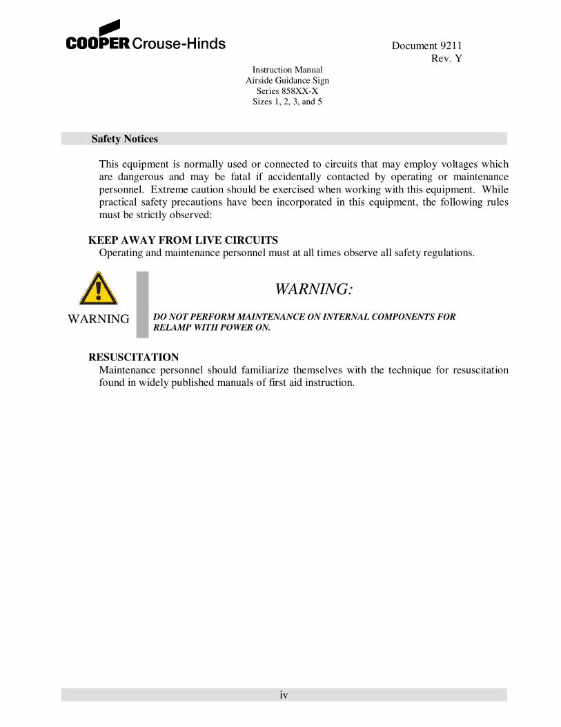
Safety Notices
This equipment is normally used or connected to circuits that may employ voltages which
are dangerous and may be fatal if accidentally contacted by operating or maintenance
personnel. Extreme caution should be exercised when working with this equipment. While
practical safety precautions have been incorporated in this equipment, the following rules
must be strictly observed:
KEEP AWAY FROM LIVE CIRCUITS Operating and maintenance personnel must at all times observe all safety regulations.
WARNING:
WARNING DO NOT PERFORM MAINTENANCE ON INTERNAL COMPONENTS FOR
RELAMP WITH POWER ON.
RESUSCITATION
Maintenance personnel should familiarize themselves with the technique for resuscitation
found in widely published manuals of first aid instruction.

Document 9211
Rev. Y Instruction Manual
Airside Guidance Sign
Series 858XX-X
Sizes 1, 2, 3, and 5
v
Safety Symbols
DANGER:
DANGER The hazard or unsafe practice will result in severe injury or death.
WARNING:
WARNING The hazard or unsafe practice could result in severe injury or death.
CAUTION:
CAUTION The hazard or unsafe practice could result in minor injury.
NOTICE:
NOTICE Possibly dangerous situation, goods might be damaged.
IMPORTANT:
IMPORTANT Helpful information.

Document 9211
Rev. Y Instruction Manual
Airside Guidance Sign
Series 858XX-X
Sizes 1, 2, 3, and 5
vi
Table of Contents
Title Page .....................................................................................................................................i
Revisions ................................................................................................................................... ii
Limited Product Warranty ......................................................................................................... iii
Safety Notices ............................................................................................................................ iv
Table of Contents ....................................................................................................................... vi
Test Equipment and Tools .......................................................................................................... ix
Section 1. General Information ................................................................................................... 1
1.1 General Description ................................................................................................... 1
1.2 Classification of Signs ............................................................................................... 1
1.3 Part Numbers ............................................................................................................. 2
Section 2. Installation ................................................................................................................. 3
Section 3. Adding Additional Sign Modules ............................................................................... 4
Section 4. Maintenance and Troubleshooting – Electrical ............................................................ 4
4.1 Lamp Current Check for Style 2 (3-step) and Style 3 (5-step) AGS Signs .................. 4
4.2 Troubleshooting 3/5 Step AGS Signs ......................................................................... 5
4.3 Lamp Current Check for Style 5 (5.5A fixed current) AGS signs ............................... 8
4.4 Lamp Replacement .................................................................................................... 8
4.4 Sign PC Board P/N 61153-1 Calibration .................................................................... 9

Document 9211
Rev. Y Instruction Manual
Airside Guidance Sign
Series 858XX-X
Sizes 1, 2, 3, and 5
vii
List of Tables
Table 1 – Troubleshooting 3/5 step signs ..................................................................................... 6
Table 2 – Three step current levels .............................................................................................. 7
Table 3 – Five step current levels ................................................................................................ 7
Table 4 – Measured Load and Power Factor (Style 2 and Style 3) ............................................. 10
Table 5 – Measured Load and Power Factor (Style 5)................................................................ 10
Table 6 – Parts list ..................................................................................................................... 11
Table 7 – Recommended two year Spare Parts Stock................................................................. 14

Document 9211
Rev. Y Instruction Manual
Airside Guidance Sign
Series 858XX-X
Sizes 1, 2, 3, and 5
viii
List of Figures
Figure 1 – Typical AGS sign, side view.................................................................................. 5
Figure 2 – Single Module Sign, Series Circuit ...................................................................... 15
Figure 3 – Double Module Sign, Series Circuit ..................................................................... 16
Figure 4 – Single Module with Join Section, Series Circuit .................................................. 17
Figure 5 – Double Module with Joint Section, Series Circuit ................................................ 18
Figure 6 – Typical Jointing of Signs ..................................................................................... 19
Figure 7 – Joint Section ........................................................................................................ 20
Figure 8 – Wiring Schematic, Single Module, 3 or 5 Step...................................................... 21
Figure 9 – Wiring Schematic, Double Module. 3 or 5 Step .................................................... 22
Figure 10 – Tapped Transformer Wiring Detail, 3/5-Step ....................................................... 23
Figure 10A – Calibration of the 61153-1 Printed Circuit Board ................................................. 24
Figure 11 – Other configurations ............................................................................................ 25
Figure 12 – Wiring Schematic, Single Module, Style 5 (5.5A Fixed Current) .......................... 26
Figure 13 – Wiring Schematic, Double Module, Style 5 (5.5A Fixed Current) ......................... 27
Figure 14 – Tapped Transformer Wiring Detail, Style 5 (5.5A Fixed Current) ........................ 28
Figure 15 – Not Used ............................................................................................................. 29
Figure 16 – Concrete Pad Dimensions .................................................................................... 30
Figure 17 – Concrete Pad Dimensions, Elbow to Base ............................................................ 31
Figure 18 – Sign Dimensions ................................................................................................. 32
Figure 19 – Mounting Detail, Steel Base ................................................................................ 33
Figure 20 – Mounting Detail, Elbow Assembly ...................................................................... 34
Figure 21 – Flange Installation ............................................................................................... 35

Document 9211
Rev. Y Instruction Manual
Airside Guidance Sign
Series 858XX-X
Sizes 1, 2, 3, and 5
ix
Test Equipment and Tools
There is a wide variety of tools and equipment needed to safely and correctly perform airfield
lighting equipment installation and maintenance. In addition to the obvious tools (screwdrivers,
wrenches, etc.), there is a specialized equipment needed to do the job.
Refer to the equipment manufacturer’s manuals for the proper use, maintenance and calibration (if
necessary) of all meters.
Multimeter
One of the most important pieces of test equipment is the Multimeter. It is used to measure
voltages, currents, and resistances. Almost every single maintenance task requires the use of a
multimeter at one point or another. A quality meter in good repair and calibration is a must because
airfield lighting power distribution equipment produces non-sinusoidal waveforms, traditional
average reading meters are inaccurate and have very limited use. Checking or adjusting equipment
based upon incorrect current reading may dramatically reduce lamp life and adversely affect power
equipment performance. A meter with TRUE RMS measuring capability and a current clamp-on
probe is needed to accurately measure distorted or chopped waveforms. All meter manufacturers
offer TRUE RMS measuring meters. The following is a short list of TRUE RMS Multimeters from
Fluke:
Manufacturer Model Number
Fluke 85III, 87III, 187, 189, 335, 336, 337
Our recommended meter is the Fluke 87III with the Fluke 80I-600A current clamp.

Document 9211
Rev. Y Instruction Manual
Airside Guidance Sign
Series 858XX-X
Sizes 1, 2, 3, and 5
1
1.0 General Information
1.1 General Description
Crouse-Hinds Airport Lighting Products, “AIRSIDE” internally illuminated Taxiway and Runway
Signs provide outstanding message visibility, day or night. White on Red and Yellow on Black and
Black on Yellow color combinations may be ordered with any desired message. Signs are available
as single or double faced and are provided with retroreflective sign face. For further information on
Taxiway Signs and their use, consult the latest revision FAA Advisory Circulars AC 150/5340-18
and AC 150/5345-44.
1.2 Classification of Signs
The signs covered in this manual are designed and manufactured in accordance with the
requirements of FAA Advisory Circular AC 150/5345-44H. Specifications for Taxiway and
Runway Signs and conform to the following classifications as indicated in paragraph 1.2 of the
above Advisory.
Types:
Type L-858Y – Direction destination and boundary sign – black legend on a yellow background.
Type L-858R – Mandatory instruction sign white legend on a red background.
Type L-858L – Taxiway and runway location sign yellow legend and border on a black
background.
A sign may consist of multiple arrays of the above messages.
NOTE: Size 5 information in this manual is the same as the Size 3 single module unless noted
otherwise. For size 4 distance marker signs, see Manual 9213.
P/N Sizes
8581X-X Size 1 – 12 inch legend (small body)
8582X-X Size 2 – 15 inch legend (mid-size body)
8583X-X Size 3 – 18 inch legend (large body)
8585X-X Size 5 – 25 inch legend (large body DMS)

Document 9211
Rev. Y Instruction Manual
Airside Guidance Sign
Series 858XX-X
Sizes 1, 2, 3, and 5
2
CAT. # FAA Styles
-3 Style 2 – For operation from a 3 step series lighting circuit (4.8 to 6.6 amperes)
-5 Style 3 – For operation from a 5 step series lighting circuit (2.8 to 6.6 amperes)
-1 Style 5 – A (fixed) 5.5 ampere series lighting circuit
Environmental Requirements
Class 2 – For operation from -55ºC to +55ºC (+131ºF)
Mode 2 – Sign for use in areas subjected to wind speed of up to 200 mph (322 km/h)
1.3 Part Numbers:
8 5 8 - - -
FAA Type:
FAA Size:
1 = Taxiway Sign, 30” High
2 = Taxiway Sign, 36” High
3 = Taxiway Sign, 42” High
4 = Distance Marker, 60” High
5 = Distance Marker, 42” High
Number of Faces: 1 = Single Face
2 = Double Face
Brightness Levels: 1 = FAA Style 5 (fixed, 5.5A)*
3 = FAA Style 2 (3 Steps, 4.8 o 6.6A)**
5 = FAA Style 3 (5 Steps, 2.8 to 6.6A)**
Number of Lamp Modules: 1 to 4 (Note: 4 Module Size 2 exceeds spec. by 0.6 in)
Options: 10 = Unenclosed Power Cable: 3 Ft. with Plug
11 = Flexible Liquidtight Conduit Enclosed 3 Ft. Power Cable
12 = External Power Switch
19 = Lamp Out Indicator
20 = Additional Tether (Single Module Sign Only)
* Use 33101 and 33102 isolation transformers only. Use step 2 of a 3 step regulator.
** Circuit board P/N 61153-1 allows for either 3 or 5 step operation, with no adjustments.
Document 9211
Rev. Y Instruction Manual
Airside Guidance Sign
Series 858XX-X
Sizes 1, 2, 3, and 5
3
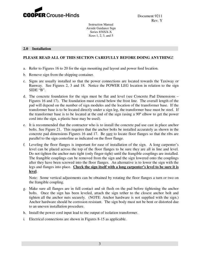
2.0 Installation
PLEASE READ ALL OF THIS SECTION CAREFULLY BEFORE DOING ANYTHING!
a. Refer to Figures 16 to 20 for the sign mounting pad layout and power feed location.
b. Remove sign from the shipping container.
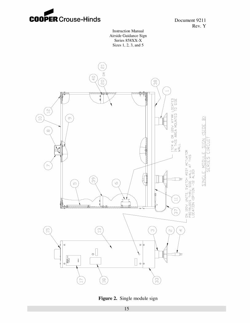
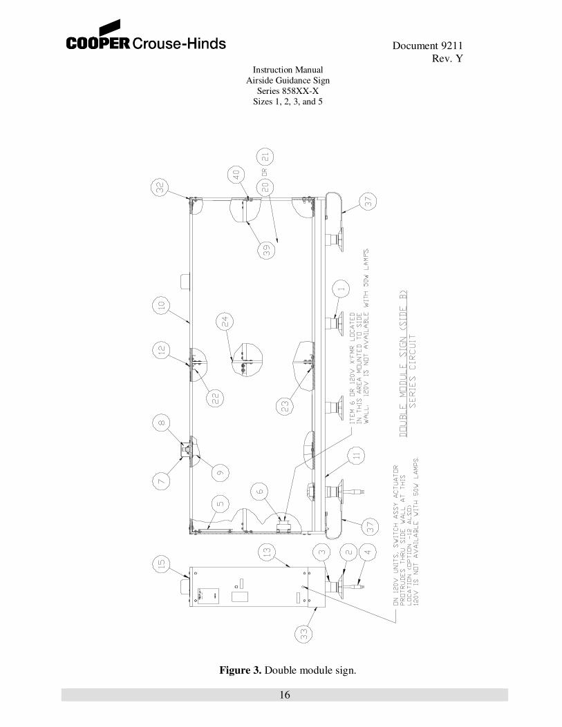
c. Signs are usually installed so that the power connections are located towards the Taxiway or
Runway. See Figures 2, 3 and 18. Notice the POWER LEG location in relation to the sign
SIDE “B”.
d. The concrete foundation for the sign must be flat and level (see Concrete Pad Dimensions –
Figures 16 and 17). The foundation must extend below the frost line. The overall length of the
pad will depend on the number of sign modules and the location of the transformer base. If the
transformer base is to be located directly under a sign leg, the transformer base must be steel. If
the transformer base is to be located at the end of the sign (using a 90º elbow to get the power
cord into the sign, a plastic base may be used).
e. It is recommended that the contractor who is to install the concrete pad use cast in place anchor
bolts. See Figure 21. This requires that the anchor bolts be installed accurately as shown in the
concrete pad dimensions Figures 16 and 17. Be sure to locate floor flanges so that the ribs are
parallel to the sign centerline as indicated on the floor flange.
f. Leveling the floor flanges is important for ease of installation of the sign. A long carpenter’s
level can be placed across the top of the floor flanges to be sure they are all in line and level.
Do not tighten the anchor nuts tight (only finger-tight) until the frangible couplings are installed.
The frangible couplings can be removed from the sign and the sign lowered onto the couplings
after they have been screwed into the floor flanges. An alternative is to lower the sign with the
legs and flanges into place. Check the sign itself with a long carpenter’s level to be sure it is
level.
Note: Some vertical adjustments can be obtained by rotating the floor flanges a turn or two on
the frangible coupling.
g. Make sure all flanges are in full contact and sit flush on the pad before tightening the anchor
bolts. Once the sign has been leveled, attach the sign tether to the closest anchor bolt and
tighten all the anchor nuts securely. (NOTE: Anchor hardware is not supplied with the sign.)
Anchor hardware should be corrosion resistant. The sign body must not be bent or distorted due
to an uneven installation procedure.
h. Install the power cord input lead to the output of isolation transformer.
i. Electrical connections are shown in Figures 8-15 as applicable.

Document 9211
Rev. Y Instruction Manual
Airside Guidance Sign
Series 858XX-X
Sizes 1, 2, 3, and 5
4
3.0 Installation of Additional Modules
If additional sign modules must be added at a later date or during initial installation, proceed as
follows:
a. See Figures 4-7.
b. Examine the construction of an existing joint section if available.
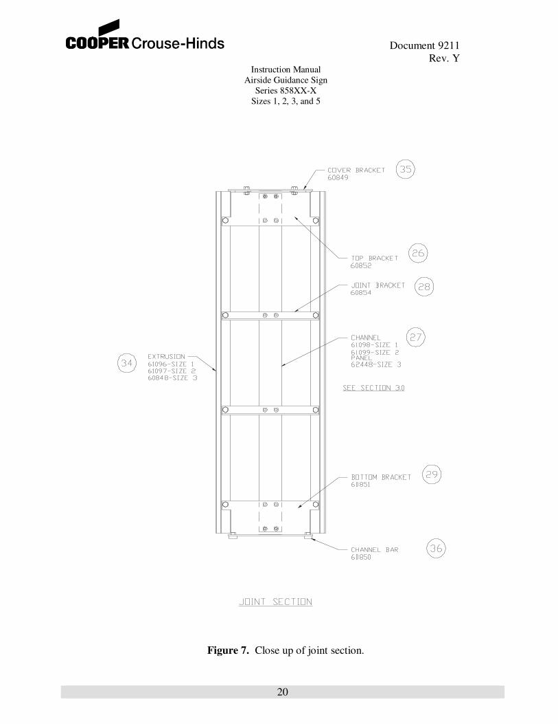
c. The joint section is designed like the end of a sign. There is an angle bracket that slides into two
vertical grooves in the extrusion. The end of the sign (See Figures 4-7) will connect to the joint
section in a manner almost identical to the opposite end of the sign.
d. After assembling the joint section, insert the four long screws in the bottom and two long screws
at the top. Tighten the screws securely. Do not over-tighten or crush the plastic extrusion. Be
sure the color of the joint section matches the sign face.
e. Color matching is as follows:
1. For yellow sign face with black and yellow face on either side of the joint, use yellow joint.
2. For red and yellow face on either side of the joint, use yellow or red. In most cases, yellow
will be provided.
3. If two red faces are used, the joint must be red.
f. Attach the sign tether to the closest anchor bolt and tighten all the anchor nuts securely
(NOTE: Anchor hardware is not supplied with the sign.) Anchor hardware should be
corrosion resistant
4.0 Maintenance and Troubleshooting – Electrical
Problems in this area should be referred to a qualified electrician due to the potential shock
hazard.
WARNING:
WARNING REMOVE POWER BEFORE ATTEMPTING ANY SERVICING.
4.1 Lamp Current Check for Style 2 (3-step) and Style 3 (5-step) AGS Signs
a. These signs are not adjustable and are calibrated at the factory. In addition, these signs
may be connected to a 3-step or 5-step CCR without any modifications. However, to
verify that the sign is operating properly, current delivered to the lamps should be
checked. After signs have been installed and with power removed, remove the lamp
access cap (see Figure 1) and use a true RMS ammeter to measure current to the lamps.

Document 9211
Rev. Y Instruction Manual
Airside Guidance Sign
Series 858XX-X
Sizes 1, 2, 3, and 5
5
Figure 1. Typical AGS sign, Side View.
b. Turn the lighting circuit on to any step and observe current through lamps. After about 3
seconds, the current should be between 5.9 and 6.4 amps (nominal is 6.2 amps). See Table 1
at the end of this section if there are any problems here or in any of the subsequent steps.
c. Repeat (b) through all steps. There may be a 2-4 second a delay between steps before lamps
are fired.
d. Re-connect lamp, install the lamp access cap and sign is ready for operation.
4.2 Troubleshooting 3/5 Step AGS Signs
When the circuit board is operating correctly, upon power up a sequence of 7 green LED’s will turn
on and off, and will settle on one of them. Once this is done, the lamp(s) will turn on at the
appropriate current (6.2 amps nominal). This circuit selects the proper tap on a transformer which
either steps up the current from the airfield current loop to 6.2 amps (nominal) or steps the current
down to 6.2 amps (nominal). The flashing sequence of LED’s at power-up is a pre-scan which
determines that all taps from the transformer are connected to the circuit board, and whether there is
a burned-out lamp or not. If there is a burned-out lamp, the circuit will immediately shunt the
lamp(s). See Table 1 below if problems are encountered.

Document 9211
Rev. Y Instruction Manual
Airside Guidance Sign
Series 858XX-X
Sizes 1, 2, 3, and 5
6
Table 1
Troubleshooting 3/5 step signs
Symptom Possible Cause/Solution
1. Lamps do not turn on
a) Lamp circuit is open. Check for open lamps, or discontinuity between L1
and L2 of Fig. 8 (single module) or between L1 and B1 of Figs 9-11.
b) Check wiring, ensure all connections between tap transformer and circuit
board are sound.
c) Check input current to circuit board at wires 1 or 10 of Figures 8-10.
Should correspond to current loop currents of Tables 2 and 3. Replace
isolation transformer if out of spec. If not, there is most likely a problem
with the circuit board.
2.Lamps do not turn on
a) Circuit cannot determine which tap to select. Check for proper current
levels as in 1 (c) above. Check thoroughly for poor connections between
the tap transformer and the circuit board. An open/loose contact can
simulate a lamp out condition, or prevent the circuit from selecting the
correct tap. In the latter case, the board will wait until a different current is
selected on the airfield. If all connections and currents check out ok, then
there is likely a bad component on the circuit board.
3. Lamps are too bright or too
dim
a) Check that current to lamps is between 5.9 and 6.4 amps. If ok, then
replace lamp(s). Old lamps can get very dim without burning out. If not
within these limits, check input current to sign. It should be within the
specifications given in Tables 2 and 3.
b) There is a problem with the circuit board. Swap out with another to check,
or replace.
4. Lamps flicker a) If using a series-type regulator, check that it is over 30% loaded. There is a lamp bypass built into the circuit that may be prematurely triggering,
thereby stealing current from the lamps. Unloaded series regulators can
produce large voltage spikes on the power line that can trigger the lamp
bypass.
b) Other sources of noise on the power line can cause the circuit to behave as
if the current step is being changed. The circuit will attempt to re-find the
ideal tap to be selected, and in the meantime the lamps may be bypassed
(no current to lamps) which causes the ‘flicker’. Contact the factory for
assistance.
5. A) Sign will not work in all
brightness levels but works in
others. B) Sign will not work in
any level but lamps and current
input are okay.
a) Do calibration procedure. See Paragraph 4.5 for calibration instructions..
b) Check that the jumpers on PC Board 61153-1 are in the correct positions.

Document 9211
Rev. Y Instruction Manual
Airside Guidance Sign
Series 858XX-X
Sizes 1, 2, 3, and 5
7
Table 2
For three step regulator circuits, the airfield current levels should be:
Regulator Setting Current Range (A, RMS)
B10 4.7-4.9
B30 5.3-5.7
B100 6.4-6.7
Table 3
For five step regulator circuits, the airfield current levels should be:
Regulator Setting Current Range (A, RMS)
B1 2.7-2.9
B2 3.3-3.5
B3 4.0-4.2
B4 5.0-5.4
B5 6.4-6.7
Note: See page ix for a list of meters that would be suitable for these measurements.

Document 9211
Rev. Y Instruction Manual
Airside Guidance Sign
Series 858XX-X
Sizes 1, 2, 3, and 5
8
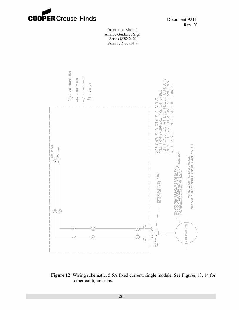
4.3 Lamp Current Check for Style 5 (5.5A fixed current) AGS signs
Note: There is no circuit board in the Style 5 sign. The Style 5 sign operates with a step-
up isolation transformer which bumps the current up to 6.2 amps from an input of 5.5
amps and drives the lamps directly.
See Figures 12-15 for schematics and wiring configurations for Style 5 signs.
a. Remove the lamp access cover nearest the power cord and use a true RMS current meter
to measure current to the lamps.
b. Turn the lighting circuit on to 5.5 amps
c. If there is no current flowing through the lamps, turn the circuit off and check the
continuity of each lamp in the sign. Replace the lamps that are open (blown). Turn the
lighting circuit on.
d. If the current level to the lamps is less than 5.9 A or greater than 6.4 amps, check the
input current to the isolation transformer to make sure it is 5.5 amps. If so, replace the
isolation transformer. Otherwise, adjust the output current of the regulator to 5.5 Amps
and repeat current check. Fortunately there is not much that can go wrong with this type
of sign so it is very easy to trouble shoot.
4.4 Lamp Replacement
The signs are wired with a maximum of four lamps per power transformer in series, which
means that when one lamp goes out, all lamps on that power transformer also go out.
WARNING:
WARNING BE SURE POWER TO THE SIGN HAS BEEN TURNED OFF.
a. Remove the lamp access cap (Figure 1) by loosening the three screws and lifting off the
cap. It may be necessary to supply power with the cover removed to determine which
lamps are out. It is recommended that all the lamps in this sign loop be replaced at this
time, however, you may choose to replace just those lamps that are burned out. Slide the
lamps into brackets, install sockets and replace the covers and turn the power back on.

Document 9211
Rev. Y Instruction Manual
Airside Guidance Sign
Series 858XX-X
Sizes 1, 2, 3, and 5
9
4.5 Sign PC Board P/N 61153-1 Calibration
The 61153-1 PC Board doesn’t normally need to be calibrated in the field if the current
levels feeding the sign are reasonably close to the nominal three or five step current levels.
If the current levels feeding the sign are substantially different from the nominal, the 61153-
1 PC Board can be calibrated in an attempt to calibrate the sign to the current levels
provided.
INSTRUCTIONS FOR CALIBRATION OF 61153-1 PC BOARD.
1. Turn the airfield circuit feeding the sign to the highest (6.6 Amp) brightness level.
CAUTION:
CAUTION The hazard or unsafe practice could result in minor injury.
2. Locate and remove the jumper “P7” from the “P7” pins on the 61153-1 PC Board.
See Figure 10A. This operation shuts the PC Board off.
3. Locate and move jumper “P5” from open position on one pin, to the closed position
on both pins in the “P5” location. This operation tells the PC Board to calibrate to the
incoming current.
4. Replace the “P7” jumper on both of the “P7” pins. This operation turns the PC Board
on in the calibrate mode.
5. Wait one minute for the PC Board to calibrate. All the lamps of the sign should be lit
and LED 8 on the PC Board will be green if the calibration is complete. LED 8 will
be flashing “red” if the circuit board did not calibrate.
6. Remove the “P7” jumper and then move the “P5” jumper back to the open position.
Replace the “P7” jumper back on both pins. This operation takes the PC Board out of
the calibration mode and puts it back in the operate mode.
7. If the Sign is calibrated, operate the sign through each step of the regulator. The
following LED’s on the PC Board will indicate green for proper operation:
5 – Step Regulator 3 – Step Regulator
Step #1 LED 7 Step #1 LED 4
Step #2 LED 6 Step #2 LED 2
Step #3 LED 5 Step #3 LED 1
Step #4 LED 3
Step #5 LED 1

Document 9211
Rev. Y Instruction Manual
Airside Guidance Sign
Series 858XX-X
Sizes 1, 2, 3, and 5
10
TABLE 4
AIRSIDE GUIDANCE SIGNS
MEASURED LOAD (VA) AND POWER FACTOR (PF)
STYLE 2 AND 3
LAMP
MODULES
ISOLATION XFMR,
PART NO. 6.6/6.6 VA @ STEP B5/B100 PF
1 33004 (100W)
100
.95 Min
2* 33006 (200W)
160
.95 Min
3 33010 (300W)
230
.95 Min
4 33010 (300W)
290
.95 Min
Applies to all FAA sizes, single and double face. Tested on a Crouse-Hinds constant current
regulator at 1/2 load. Measured wattage exceeds the total of the lamp wattage due to the power
consumption of the sign internal electrical system.
*Includes FAA Size 4 distance marker sign
TABLE 5 AIRSIDE GUIDANCE SIGN
MEASURED LOAD (VA) AND POWER FACTOR (PF)
STYLE 5 (FIXED 5.5A CURRENT)
LAMP MODULES
ISOLATION
TRANSFORMER, PART
NO. 5.5/6.2A VA PF
1
33101 (100W) 100 .95 min
2
33102 (200W) 160 .95 min
3
33101 & 33102 (300W) * 230 .95 min
4
33101 & 33102 (300W) * 290 .95 min
* Use Consolidating Harness P/N 26811-27

Document 9211
Rev. Y Instruction Manual
Airside Guidance Sign
Series 858XX-X
Sizes 1, 2, 3, and 5
11
Parts List
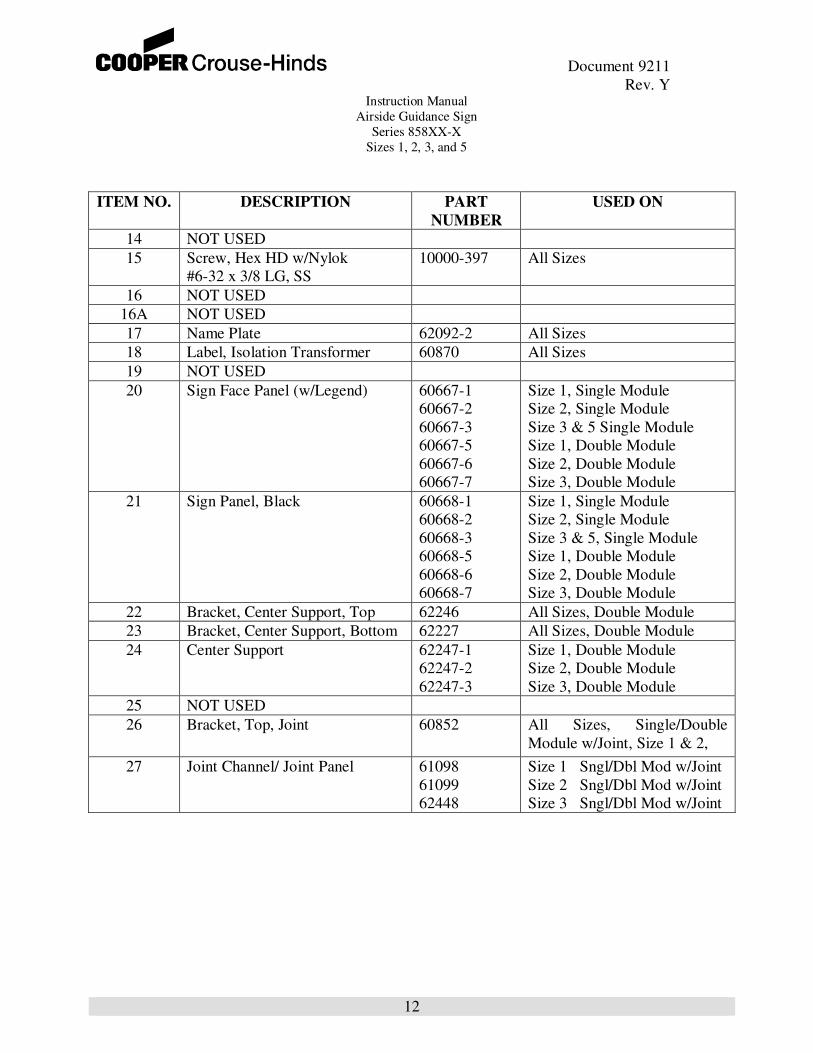
TABLE 6
See Figures 2 – 7 for item location
ITEM NO. DESCRIPTION PART
NUMBER
USED ON
1 Frangible Coupling 62245-1
62245-2
62245-3
62245-5
Size 1
Size 2
Size 3
Size 5
2 Floor Flange 25684-1 All Sizes
3 Leg 60684 All Sizes
4 Power Cord CAS1M-P-B-.86 All Sizes
5 PC Board Assembly (for item 8
lamps)
61153-1
3-Step or 5-Step circuits
6 Tapped Transformer 61143 All Sizes
7 Lamp Cap 60638 All Sizes
8 Lamp, 62W 20590 All Sizes
9 Light Tube Assembly 60685-1
60685-2
60685-3
Size 1
Size 2
Size 3 & 5
10 Cover 62243-1
62243-2
62243-3
62243-5
62243-6
62243-7
Size 1, Single Module
Size 2, Single Module
Size 3 & 5, Single Module
Size 1, Double Module
Size 2, Double Module
Size 3, Double Module
11 Bottom 60758-1
60759-1
60760-1
60758-2
60759-2
60760-2
Size 1, Single Module
Size 2, Single Module
Size 3 & 5, Single Module
Size 1, Double Module
Size 2, Double Module
Size 3, Double Module
12 Screw, Hex HD w/Nylok
1/4-20 X 1” LG, SS (7/16”
socket)
10000-405 All Sizes
13 Side 60615-1A
60615-2A
60615-3A
Size 1
Size 2
Size 3 & 5
Document 9211
Rev. Y Instruction Manual
Airside Guidance Sign
Series 858XX-X
Sizes 1, 2, 3, and 5
12
ITEM NO. DESCRIPTION PART
NUMBER
USED ON
14 NOT USED
15 Screw, Hex HD w/Nylok
#6-32 x 3/8 LG, SS
10000-397 All Sizes
16 NOT USED
16A NOT USED
17 Name Plate 62092-2 All Sizes
18 Label, Isolation Transformer 60870 All Sizes
19 NOT USED
20 Sign Face Panel (w/Legend)
60667-1
60667-2
60667-3
60667-5
60667-6
60667-7
Size 1, Single Module
Size 2, Single Module
Size 3 & 5 Single Module
Size 1, Double Module
Size 2, Double Module
Size 3, Double Module
21 Sign Panel, Black 60668-1
60668-2
60668-3
60668-5
60668-6
60668-7
Size 1, Single Module
Size 2, Single Module
Size 3 & 5, Single Module
Size 1, Double Module
Size 2, Double Module
Size 3, Double Module
22 Bracket, Center Support, Top 62246 All Sizes, Double Module
23 Bracket, Center Support, Bottom 62227 All Sizes, Double Module
24 Center Support 62247-1
62247-2
62247-3
Size 1, Double Module
Size 2, Double Module
Size 3, Double Module
25 NOT USED
26 Bracket, Top, Joint 60852 All Sizes, Single/Double
Module w/Joint, Size 1 & 2,
27 Joint Channel/ Joint Panel 61098
61099
62448
Size 1 Sngl/Dbl Mod w/Joint
Size 2 Sngl/Dbl Mod w/Joint
Size 3 Sngl/Dbl Mod w/Joint

Document 9211
Rev. Y Instruction Manual
Airside Guidance Sign
Series 858XX-X
Sizes 1, 2, 3, and 5
13
ITEM NO. DESCRIPTION PART
NUMBER
USED ON
28 Bracket, Joint 60854 Size 2, Single/Double Module
w/Joint
29 Bracket, Bottom, Joint 60851 Size 1 & 2, Single/Double
Module w/Joint
30 Channel Support 60783 All Sizes, Single/Double
Module w/Joint
32 Rain Cap, End 60633 All Sizes
33 Rain Cap, Joint/Bottom 60634 All Sizes, Single/Double
Module w/Joint
34 Plastic Extrusion, Machined 61096
61097
60848
Size 1 Sngl/Dbl Mod w/Joint
Size 2 Sngl/Dbl Mod w/Joint
Size 3 Sngl/Dbl Mod w/Joint
35 Cover Bracket 60849 All Sizes w/Joint
36 Channel Bar 60850 All Sizes w/Joint
37 Tether 60728-1 All sizes
38 Hole Plug 10037-621 All Sizes - Single Module
All Sizes - Joint Sections
Single and Double
39 Center Support, Horizontal 62242-3 Size 3 w/ and w/o Joint
Sections, Single and Double
40 Bracket, Center Support, Middle 62244 Size 3 w/ and w/o Joint
Sections, Single and Double
41 Bracket Joint Panel 62249 Size 3 w/ Joint
Note: 3 and 4 module signs are combinations of single and double module signs as shown in
Figures 11 and 15.

Document 9211
Rev. Y Instruction Manual
Airside Guidance Sign
Series 858XX-X
Sizes 1, 2, 3, and 5
14
RECOMMENDED TWO YEAR SPARE PARTS STOCK
TABLE 7
DESCRIPTION
PART NUMBER RECOMMEDED QUANITY
Lamp, 62W. 20590 1 Per Module
Lamp Socket 61107 1 Per Every 20 Modules
Circuit Card 61153-1 1 Per Every 20 Signs
*Frangible Coupling 62245-X 1 Set Per Every 20 Signs
Internal Tapped X’fmr 61143 1 Per Every 20 Signs
**Cover Assembly
(includes cap, gasket and lamp
screws)
60844-X 1 Per Every 25 Signs
Lamp Cap 60638 1 Per Every 25 Signs
* = -1 For Size 1
-2 For Size 2
-3 For Size 3
-5 For Size 5
** = 60844-1 For Size 1 Single
60844-2 For Size 2 Single
60844-3 For Size 3 Single
60844-5 For Size 1 Double
60844-6 For Size 2 Double
60844-7 For Size 3 Double
Document 9211
Rev. Y Instruction Manual
Airside Guidance Sign
Series 858XX-X
Sizes 1, 2, 3, and 5
15
Figure 2. Single module sign
Document 9211
Rev. Y Instruction Manual
Airside Guidance Sign
Series 858XX-X
Sizes 1, 2, 3, and 5
16
Figure 3. Double module sign.

Document 9211
Rev. Y Instruction Manual
Airside Guidance Sign
Series 858XX-X
Sizes 1, 2, 3, and 5
17
Figure 4. Single module with joint section

Document 9211
Rev. Y Instruction Manual
Airside Guidance Sign
Series 858XX-X
Sizes 1, 2, 3, and 5
18
Figure 5. Double module with joint section.

Document 9211
Rev. Y Instruction Manual
Airside Guidance Sign
Series 858XX-X
Sizes 1, 2, 3, and 5
19
Figure 6. Joining of signs.
Document 9211
Rev. Y Instruction Manual
Airside Guidance Sign
Series 858XX-X
Sizes 1, 2, 3, and 5
20
Figure 7. Close up of joint section.

Document 9211
Rev. Y Instruction Manual
Airside Guidance Sign
Series 858XX-X
Sizes 1, 2, 3, and 5
21
Figure 8: Wiring schematic, single module, 3/5 Step. See Figure 10 if P/N 61143 is Rev B.
See Figures 9 and 11 for other configurations.

Document 9211
Rev. Y Instruction Manual
Airside Guidance Sign
Series 858XX-X
Sizes 1, 2, 3, and 5
22
Figure 9: Wiring schematic, double module, 3/5 step. See Figure 10 if P/N 61143 is Rev B.
See Figures 8 and 11 for other configurations.

Document 9211
Rev. Y Instruction Manual
Airside Guidance Sign
Series 858XX-X
Sizes 1, 2, 3, and 5
23
Figure 10: Wiring connections for P/N 61153 PCB to P/N 61143 tap transformer, Rev B or
Rev C. See Figures 8, 9 and 11 for more details.
T7
3 STEP T6
5 STEP T5
T9 FOR 65W,
6.6A LAMP
3 & 5 STEP
T4
A3 & T2
T8
5 STEP T6,
ALSO T9 FOR50W, 12V LAMP
3 & 5 STEP
3 STEP T5
P/N 61143
REV BACE-12534
REV B of P/N 61143, Tap transformer
T7
T6 (3)
T5 (5)
T9
T4
T11 &
T2
T8
T6 (5)
T5 (3)
REV C of 61143
P/N 61143
REV C
ACE-12534
Rev C of
61143 is a
change in
label only
E10
E11
E1
E9
E8
E7
E6 (
5)
E6 (
3)
E5 (
3)
E5 (
5)
E4
E2
E3
A4
FE
MA
LE
CO
UP
LE
R
MA
LE
CO
UP
LE
R
InputPower
B1
A1
To
: T
8
To
: T
7
To
: T
6 (
3)
To
: T
11 &
T2
As per label on 61143 REV C.For 61143 REV B, simply match corresponding tab location
To
: T
9
To
: T
6 (
5)
To
: T
5 (
5)
To
: T
5 (
3)
To
: T
4
To
: T
11 &
T2
plu
g i
nto
back o
f E
11
E1- E9 = FEMALE COUPLERSE11 = FEMALE W/MALE COUPLER
1 TO 4 62 W LAMPS
P/N 61153-1

Document 9211
Rev. Y Instruction Manual
Airside Guidance Sign
Series 858XX-X
Sizes 1, 2, 3, and 5
24
Figure 10A Calibration of the 61153-1 Printed Circuit Board.

Document 9211
Rev. Y Instruction Manual
Airside Guidance Sign
Series 858XX-X
Sizes 1, 2, 3, and 5
25
Figure 11: Other Configurations.
Fig
ure
11
. W
irin
g s
ch
em
es f
or
3 a
nd
4 m
od
ule
sig
ns (
no
t sho
wn in
Fig
s 8
an
d 9
).
V
iew
ed
fro
m A
-sid
e (
PC
boa
rd/I
np
ut
po
wer
on
rig
ht)
.
L2
PC BoardA
4
E3
L1
L2
L4
L1
B2
B1
B2
B1
L3
Join
t S
ectio
n
Doub
le M
odule
Sin
gle
Module
L2
L4
L3
B2
B1
PC BoardA
4
E3
L2
L4
L1
L3
B2
B1
L1
Join
t S
ection
Do
uble
Modu
leD
ou
ble
Modu
le
PC Board
A4
E3
L1
L2
L4
L1
L3
B2
B1
L2
B1
B2
Join
t S
ection
Dou
ble
Modu
leS
ing
le M
odule
Document 9211
Rev. Y Instruction Manual
Airside Guidance Sign
Series 858XX-X
Sizes 1, 2, 3, and 5
26
Figure 12: Wiring schematic, 5.5A fixed current, single module. See Figures 13, 14 for
other configurations.

Document 9211
Rev. Y Instruction Manual
Airside Guidance Sign
Series 858XX-X
Sizes 1, 2, 3, and 5
27
Figure 13: Wiring schematic, 5.5A fixed current, double module. See Figures 12 and 14 for
other configurations.
Document 9211
Rev. Y Instruction Manual
Airside Guidance Sign
Series 858XX-X
Sizes 1, 2, 3, and 5
28
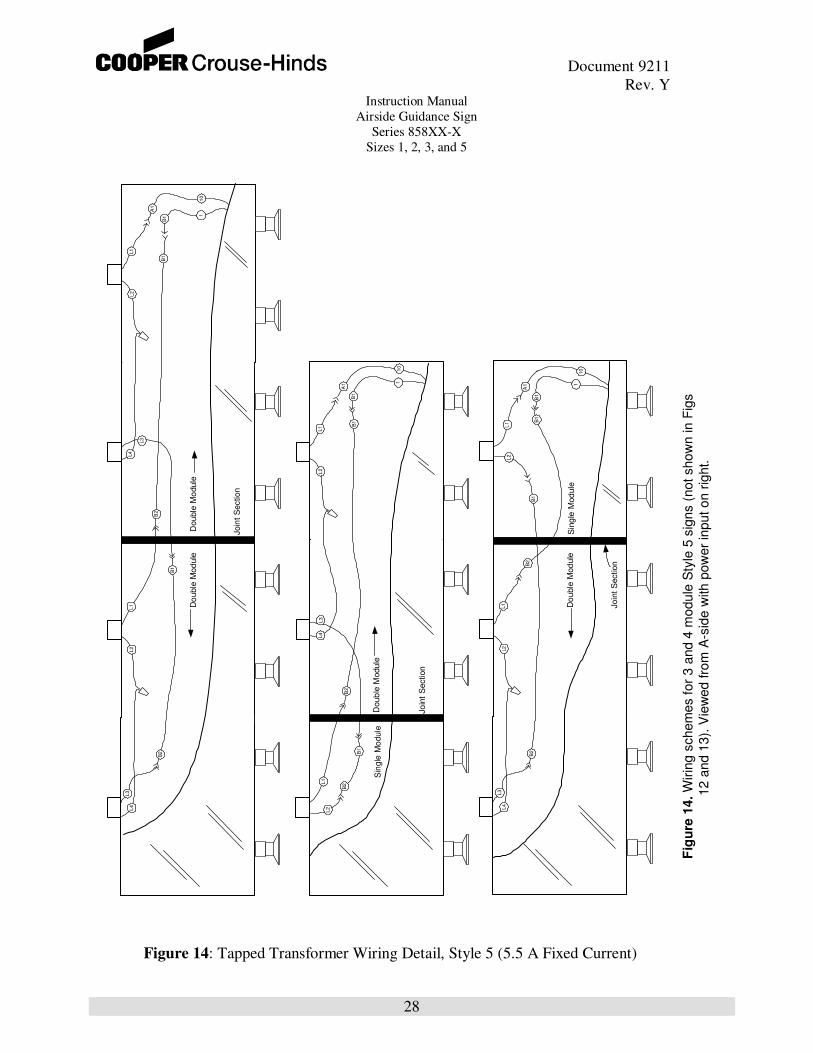
Figure 14: Tapped Transformer Wiring Detail, Style 5 (5.5 A Fixed Current)
Fig
ure
14. W
irin
g s
chem
es for
3 a
nd 4
module
Sty
le 5
sig
ns (
not show
n in F
igs
1
2 a
nd 1
3).
Vie
wed fro
m A
-sid
e w
ith p
ow
er
input on r
ight.
L2
L4
L3
B2
B1
L2
L4
L1
L3
B2
B1
L1
Double
Mo
dule
Do
uble
Mod
ule
Join
t S
ection
L2
B1
A1
L1
L2
L4
L1
B2
B1
B2
B1
L3
Jo
int
Section
Doub
le M
odule
Sin
gle
Mo
dule
B1
A1
L1
L2
L4
L1
L3
B2
B1
L2
B1
B2
Join
t S
ection
Do
uble
Mod
ule
Sin
gle
Mod
ule
B1
A1
11
0
1 1101
0

Document 9211
Rev. Y Instruction Manual
Airside Guidance Sign
Series 858XX-X
Sizes 1, 2, 3, and 5
29
THIS SHEET INTENTIONALLY LEFT BLANK
Figure 15: NOT USED

Document 9211
Rev. Y Instruction Manual
Airside Guidance Sign
Series 858XX-X
Sizes 1, 2, 3, and 5
30
Figure 16 Concrete pad dimensions

Document 9211
Rev. Y Instruction Manual
Airside Guidance Sign
Series 858XX-X
Sizes 1, 2, 3, and 5
31
Figure 17: Concrete pad dimensions, elbow to base

Document 9211
Rev. Y Instruction Manual
Airside Guidance Sign
Series 858XX-X
Sizes 1, 2, 3, and 5
32
Figure 18: Sign dimensions

Document 9211
Rev. Y Instruction Manual
Airside Guidance Sign
Series 858XX-X
Sizes 1, 2, 3, and 5
33
Figure 19: Mounting detail, steel base

Document 9211
Rev. Y Instruction Manual
Airside Guidance Sign
Series 858XX-X
Sizes 1, 2, 3, and 5
34
Figure 20: Mounting detail, Elbow Assy

Document 9211
Rev. Y Instruction Manual
Airside Guidance Sign
Series 858XX-X
Sizes 1, 2, 3, and 5
35
FLANGE INSTALLATION WITH 'L' ANCHOR BOLTS
ANCHOR BOLTS MUST BE CAPABLE OF WITHSTANDING A MINIMUM
BOLT MATERIAL TO BE ZINC GALVANIZED STEEL OR STAINLESS STEEL
USE FOUR (4) 'L' TYPE ANCHOR BOLTS PER FLANGE, #1/2-13 x 8" MINIMUM
PULL-OUT (TENSION) LOAD OF 8750 POUNDS.
FIGURE 21: Flange Installation
6.75" (171.45mm) MINIMUM
1.25" (31.75mm) REF
1
1