4x70A Implementation Guide PROFINET
12
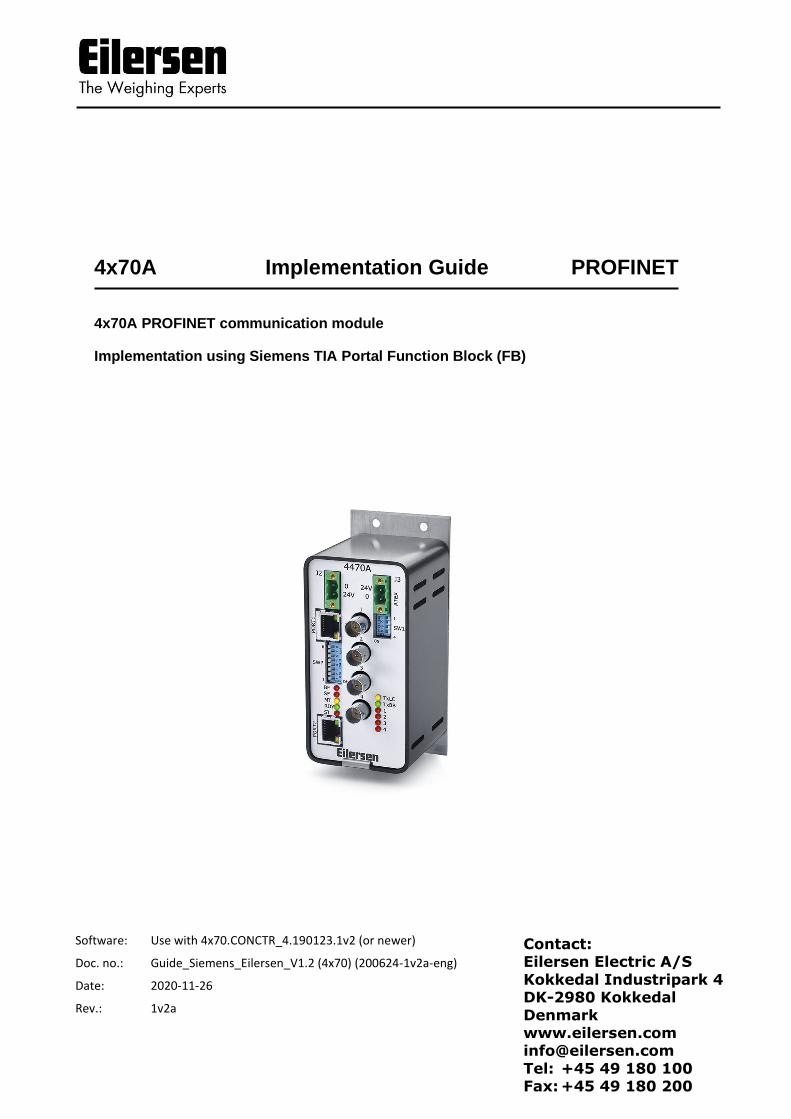
Software: Use with 4x70.CONCTR_4.190123.1v2 (or newer) Doc. no.: Guide_Siemens_Eilersen_V1.2 (4x70) (200624-1v2a-eng) Date: 2020-11-26 Rev.: 1v2a Contact: Eilersen Electric A/S Kokkedal Industripark 4 DK-2980 Kokkedal Denmark www.eilersen.com [email protected] Tel: +45 49 180 100 Fax: +45 49 180 200 4x70A Implementation Guide PROFINET 4x70A PROFINET communication module Implementation using Siemens TIA Portal Function Block (FB)
Transcript of 4x70A Implementation Guide PROFINET
Software: Use with 4x70.CONCTR_4.190123.1v2 (or newer)
Doc. no.: Guide_Siemens_Eilersen_V1.2 (4x70) (200624-1v2a-eng)
Date: 2020-11-26
Rev.: 1v2a
Contact: Eilersen Electric A/S
Kokkedal Industripark 4 DK-2980 Kokkedal
Denmark www.eilersen.com [email protected]
Tel: +45 49 180 100 Fax: +45 49 180 200
4x70A Implementation Guide PROFINET
4x70A PROFINET communication module
Implementation using Siemens TIA Portal Function Block (FB)

2
WWW.EILERSEN.COM
Contents
Contents ...................................................................................................................................... 2
Introduction ................................................................................................................................ 3
Import Library ............................................................................................................................. 3
Install GSD file ............................................................................................................................. 4
Use of the GSD device ............................................................................................ 4
Installation of Function Block (FB) .............................................................................................. 4
Description of the Function Block............................................................................................... 5
Installation of HMI Screen .......................................................................................................... 6
Pop-ups .................................................................................................................. 6
HMI Functionality ....................................................................................................................... 7
First time usage .................................................................................................... 11
Revision History ........................................................................................................................ 12
Contact ...................................................................................................................................... 12
3
WWW.EILERSEN.COM
Introduction
This document is a guide for implementation of an PROFINET interface for Eilersen capacitive
load cells, with a Siemens TIA Portal Function Block (FB).
The software library also includes one HMI Screen, with six pop-up screens.
IMPORTANT:
Please note that this PLC program block is only intended as an example for inspiration and
is not as such a product on which Eilersen Electric A/S offers any warranty or support.
Furthermore, Eilersen Electric A/S is not responsible for any loss or damage caused as a re-
sult of using this program block.
Unauthorized copying and distribution of the program block is prohibited as it is the prop-
erty of Eilersen Electric A/S.
Import Library
When installing the Function Block and HMI Screen, you will have to drag and drop from the
“Eilersen 4X70A” library. The installation of this library is described in this section.
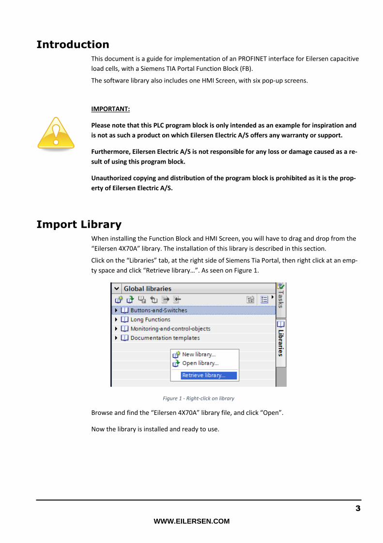
Click on the “Libraries” tab, at the right side of Siemens Tia Portal, then right click at an emp-
ty space and click “Retrieve library…”. As seen on Figure 1.
Figure 1 - Right-click on library
Browse and find the “Eilersen 4X70A” library file, and click “Open”.
Now the library is installed and ready to use.
4
WWW.EILERSEN.COM
Install GSD file
In this section you will be guided through on how to install the GSD file. The latest GSD file,
for this Profinet module, can be found on the Eilersen website.
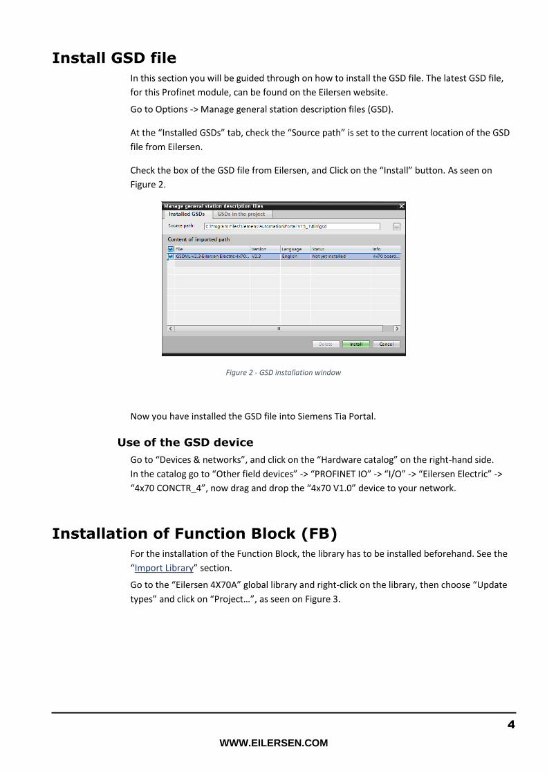
Go to Options -> Manage general station description files (GSD).
At the “Installed GSDs” tab, check the “Source path” is set to the current location of the GSD
file from Eilersen.
Check the box of the GSD file from Eilersen, and Click on the “Install” button. As seen on
Figure 2.
Figure 2 - GSD installation window
Now you have installed the GSD file into Siemens Tia Portal.
Use of the GSD device
Go to “Devices & networks”, and click on the “Hardware catalog” on the right-hand side.
In the catalog go to “Other field devices” -> “PROFINET IO” -> “I/O” -> “Eilersen Electric” ->
“4x70 CONCTR_4”, now drag and drop the “4x70 V1.0” device to your network.
Installation of Function Block (FB)
For the installation of the Function Block, the library has to be installed beforehand. See the
“Import Library” section.
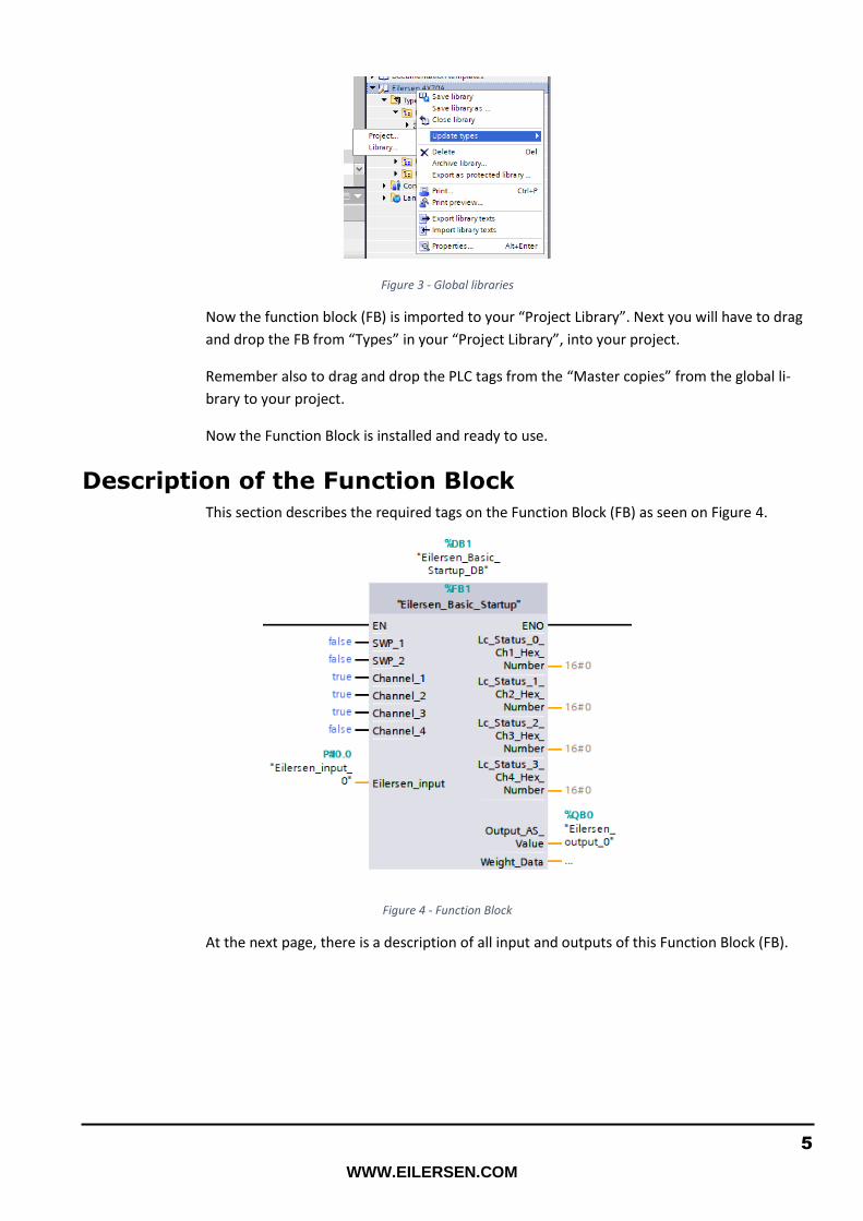
Go to the “Eilersen 4X70A” global library and right-click on the library, then choose “Update
types” and click on “Project…”, as seen on Figure 3.
5
WWW.EILERSEN.COM
Figure 3 - Global libraries
Now the function block (FB) is imported to your “Project Library”. Next you will have to drag
and drop the FB from “Types” in your “Project Library”, into your project.
Remember also to drag and drop the PLC tags from the “Master copies” from the global li-
brary to your project.
Now the Function Block is installed and ready to use.
Description of the Function Block
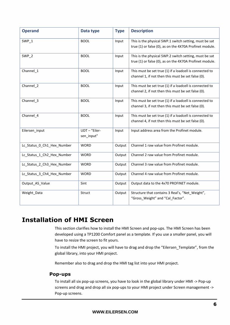
This section describes the required tags on the Function Block (FB) as seen on Figure 4.
Figure 4 - Function Block
At the next page, there is a description of all input and outputs of this Function Block (FB).
6
WWW.EILERSEN.COM
Operand Data type Type Description
SWP_1 BOOL Input This is the physical SWP.1 switch setting, must be sat
true (1) or false (0), as on the 4X70A Profinet module.
SWP_2 BOOL Input This is the physical SWP.2 switch setting, must be sat
true (1) or false (0), as on the 4X70A Profinet module.
Channel_1 BOOL Input This must be set true (1) if a loadcell is connected to
channel 1, if not then this must be set false (0).
Channel_2 BOOL Input This must be set true (1) if a loadcell is connected to
channel 2, if not then this must be set false (0).
Channel_3 BOOL Input This must be set true (1) if a loadcell is connected to
channel 3, if not then this must be set false (0).
Channel_4 BOOL Input This must be set true (1) if a loadcell is connected to
channel 4, if not then this must be set false (0).
Eilersen_input UDT – “Eiler-
sen_input”
Input Input address area from the Profinet module.
Lc_Status_0_Ch1_Hex_Number WORD Output Channel 1 raw value from Profinet module.
Lc_Status_1_Ch2_Hex_Number WORD Output Channel 2 raw value from Profinet module.
Lc_Status_2_Ch3_Hex_Number WORD Output Channel 3 raw value from Profinet module.
Lc_Status_3_Ch4_Hex_Number WORD Output Channel 4 raw value from Profinet module.
Output_AS_Value Sint Output Output data to the 4x70 PROFINET module.
Weight_Data Struct Output Structure that contains 3 Real’s, “Net_Weight”,
“Gross_Weight” and “Cal_Factor”.
Installation of HMI Screen
This section clarifies how to install the HMI Screen and pop-ups. The HMI Screen has been
developed using a TP1200 Comfort panel as a template. If you use a smaller panel, you will
have to resize the screen to fit yours.
To install the HMI project, you will have to drag and drop the “Eilersen_Template”, from the
global library, into your HMI project.
Remember also to drag and drop the HMI tag list into your HMI project.
Pop-ups
To install all six pop-up screens, you have to look in the global library under HMI -> Pop-up
screens and drag and drop all six pop-ups to your HMI project under Screen management ->
Pop-up screens.

7
WWW.EILERSEN.COM
HMI Functionality
In this section there are shown pictures from the HMI screen and all of the pop-up screens.
Figure 5 - HMI Front screen
On the HMI screen, there are shown two parameter values: “Net” and “Gross” weight. See
Figure 5.
Each of the parameters has a button for zeroing the weight:
• “Tare (Zero net weight)”
and
• “>0< (Zero gross weight)”
When either of these buttons are pressed, a warning associated to that button are shown, as
seen on Figure 6 and Figure 7.
Figure 7 - Tare warning display Figure 6 - >0< warning display

8
WWW.EILERSEN.COM
Figure 8 - AS mode popup
The alarm indicator seen on Figure 5, goes from green to red only if a major alarm occurs.
There is also a live graph of both the Net and Gross weight, as seen on Figure 5.
When the “Select AS Mode” button is pressed a popup appears, see Figure 8.
Here it is possible to select between four modes, which are:
• Standard: Filtered and scaled (Default mode)
• Mode 1: Filtered but not scaled (The signal is not scaled but it is “adjusted by the calibra-
tion factor” E.g. if there are 3 legs on a tank and only 1 load cell, the signal
weight shown will be tripled)
• Mode 2: Not filtered and not scaled (The signal is not scaled but it is “adjusted by the cali-
bration factor”)
• Mode 6 (Test mode): shows hardcoded signal values
These “AS” modes are described in more details in Eilersen user manual for the 4x70 module.
When the “Calibration” button is pressed, a popup appears, see Figure 9.
Figure 9 - Calibration popup-window
9
WWW.EILERSEN.COM
From here it is possible to calibrate the weighing system.
Enter the known weight into the input display (in gram) and then pressing the “Weight cho-
sen. Calibrate now” button.
You can also adjust the calibrating factor by pressing the input display.
Beware that if you press the “Weight chosen. Calibrate now” button, after you manually ad-
justed the calibrating factor, then this manual change will not take effect.
After the system is calibrated you can see the calibrating factor by pressing the “Service” but-
ton.
Make sure that the calibration factor is not too far from what is described in Eilersen user
manual section “System calibration of weighing system”.
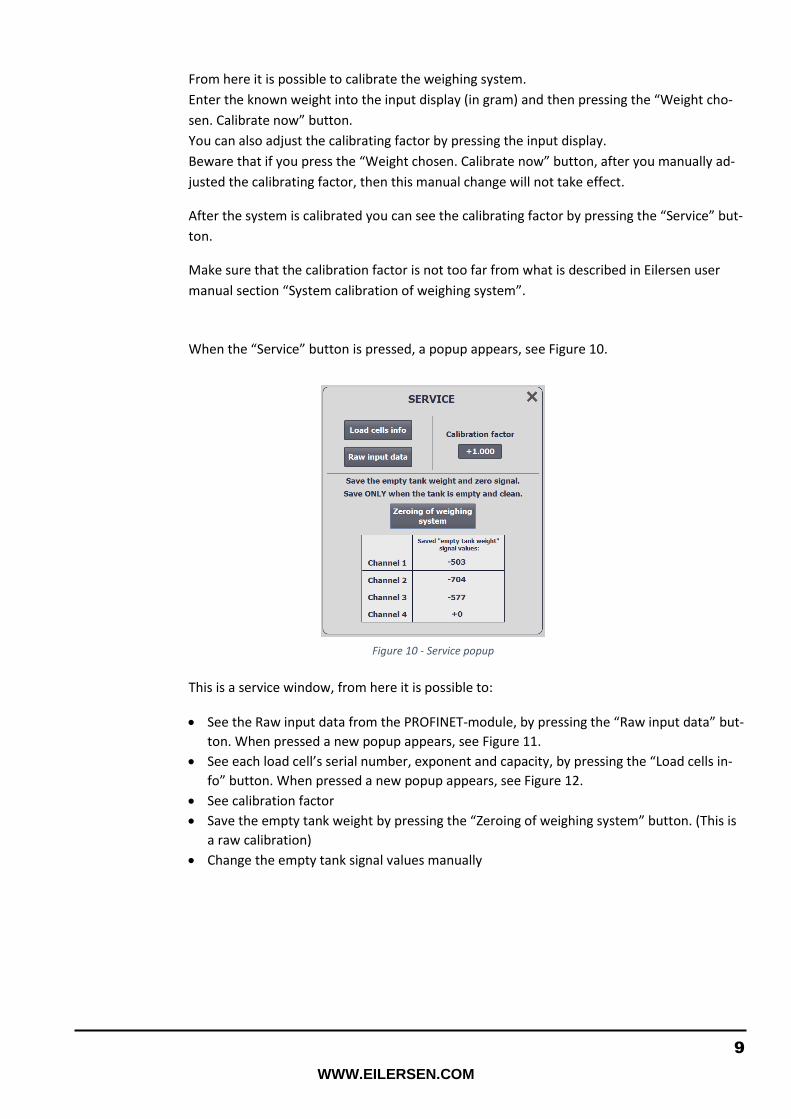
When the “Service” button is pressed, a popup appears, see Figure 10.
This is a service window, from here it is possible to:
• See the Raw input data from the PROFINET-module, by pressing the “Raw input data” but-
ton. When pressed a new popup appears, see Figure 11.
• See each load cell’s serial number, exponent and capacity, by pressing the “Load cells in-
fo” button. When pressed a new popup appears, see Figure 12.
• See calibration factor
• Save the empty tank weight by pressing the “Zeroing of weighing system” button. (This is
a raw calibration)
• Change the empty tank signal values manually
Figure 10 - Service popup

10
WWW.EILERSEN.COM
When the button “Select Weight Unit” is pressed, a popup appears, see Figure 13.
From the popup it is possible to choose between the weight units: Gram, Kg, Ton.
It is not possible to choose a weight unit if an error is active.
Figure 13 - Select weight unit pop-up
Figure 11 - Raw input data from PROFINET-module
Figure 12 - Load cells info popup

11
WWW.EILERSEN.COM
First time usage
• Make sure that the tank on the load cells is empty and clean.
• Press “Service” and then press the “Zeroing of weighing system” button.
• Put the calibration weight in / on the tank.
• Press the “Calibration” button. Enter the calibration weight into the input display in gram.
• Press the “Weight chosen. Calibrate now” button.
• Make sure that the weight now showing on the “Frontscreen”, is the same as the calibra-
tion weight.

12
WWW.EILERSEN.COM
Revision History
Date Author Rev. Update
2020-08-21 HJA 1v2 Initial document created.
(based on Guide_Siemens_Eilersen_V1.2)
2020-11-26 HJA 1v2a Added disclaimer in the introduction.
Contact
With further questions or improvement suggestions please contact us:
Eilersen Electric A/S
Kokkedal Industripark 4
DK-2980 Kokkedal
Denmark
www.eilersen.com
Tel: +45 49 180 100
Fax: +45 49 180 200