
Installation Guide PROFINET Card
28
Installation Guide PROFINET Card VLT® Soft Starter MCD 600 vlt-drives.danfoss.com
Transcript of Installation Guide PROFINET Card

Installation Guide
PROFINET CardVLT® Soft Starter MCD 600
vlt-drives.danfoss.com

11.1
1.2
22.1
2.2
2.3
33.1
3.2
3.2.1
3.2.2
3.2.3
3.3
3.4
44.1
4.1.1
4.2
4.3
4.3.1
4.3.2
4.3.2.1
4.3.2.2
4.3.3
4.3.3.1
4.3.3.2
4.4
55.1
5.2
5.3
5.4
ContentsSafety 5
Disclaimer 5
Warnings 5
Introduction 6Product Design 6
Compatibility 6
Network Connection 6
Installation 7Installing the Expansion Card 7
Network Connections 7
Ethernet Ports 7
Cables 7
EMC Precautions 7
Network Establishment 7
Addressing 7
Device Configuration 8Configuration of Device Name 8
Identifying the Device with Ethernet Device Configuration Tool 8
Enabling Network Control 9
On-board Web Server 9
Connect to the Device 9
Manage Users and Passwords 10
Adding a User 11
Deleting a User 11
Configure IoT Settings 11
Configuring MQTT Settings 12
Configuring OPC UA Settings 13
Master Configuration 13
Operation 14Requirements for Successful Operation 14
Device Classification 14
Ensuring Safe and Successful Control 14
Feedback LEDs 14
AN353424578485en-000101/130R0947 | 3Danfoss A/S © 2020.12
Contents
PROFINET Card
Installation Guide
66.1
6.2
6.3
6.3.1
6.3.2
6.3.3
6.3.4
6.3.5
6.3.6
6.4
6.4.1
6.4.2
6.5
6.6
6.6.1
6.6.2
6.6.3
77.1
7.2
7.3
7.4
88.1
8.2
8.3
8.4
8.5
Packet Structures 15Important Information 15
Control Commands (Controller to Device) 15
Status Information (Device to Controller) 15
Bytes 0–1: Control Status 15
Bytes 2–3: Starter State 16
Bytes 4–5: Trip Code 16
Bytes 6–7: Motor Current 16
Bytes 8–9: Motor Temperature 16
Bytes 10–63: Extended Information 17
Parameter Management 18
Output 19
Input 19
Trip Codes 19
Examples 21
Control Commands (Controller to Device) 21
Status Information (Device to Controller) 22
Parameter Management 22
Network Design 23Star Topology 23
Line Topology 23
Ring Topology 24
Combined Topologies 24
Specifications 26Connections 26
Settings 26
Network 26
Power 26
Certification 26
AN353424578485en-000101/130R09474 | Danfoss A/S © 2020.12
Contents
PROFINET Card
Installation Guide
-
--
1 Safety
1.1 DisclaimerThe examples and diagrams in this manual are included solely for illustrative purposes. The information contained in this manual issubject to change at any time and without prior notice. Responsibility or liability is never accepted for direct, indirect, or consequen-tial damage resulting from the use or application of this equipment.
1.2 Warnings
W A R N I N GSHOCK HAZARDAttaching or removing accessories while the soft starter is connected to mains voltage may cause personal injury.
Before attaching or removing accessories, isolate the soft starter from mains voltage.
W A R N I N GRISK OF PERSONAL INJURY AND EQUIPMENT DAMAGEInserting foreign objects or touching the inside of the soft starter while the expansion port cover is open may endanger person-nel and can damage the soft starter.
Do not insert foreign objects in the soft starter with the port cover open.
Do not touch the inside of the soft starter with the port cover open.
AN353424578485en-000101 / 130R0947 | 5Danfoss A/S © 2020.12
Safety
PROFINET Card
Installation Guide
2 Introduction
2.1 Product DesignThe PROFINET Card allows the soft starter to connect to an Ethernet network and be controlled or monitored using an Ethernetcommunication model.Familiarity with Ethernet protocols and networks is required to operate the device successfully. For difficulties arising from usingthis device with 3rd-party products, including PLCs, scanners, and commissioning tools, contact the relevant supplier.
2.2 CompatibilityThis communication expansion card is suitable for use with VLT® Soft Starter MCD 600.This Installation Guide is intended for use with version 3.x of the VLT® Soft Starter MCD 600 PROFINET Card. Earlier versions of thePROFINET Card do not support custom users, TCP connection, or IoT operation.
2.3 Network ConnectionTable 1: Supported Protocols
Protocols
PROFINET Industrial Ethernet via PROFINET
TCP Transmission control protocol to connect to port 4000 of a PC
MQTT Message queue telemetry transport
OPC UA Open platform communications unified architecture
4/T2
READY RUN TRIP LOCAL
ExitReset
MenuStore
2/T1 6/T31/L1 3/L2 5/L3
VLT®
Soft Starter
1
2
4
3
5
e77h
a805
.10
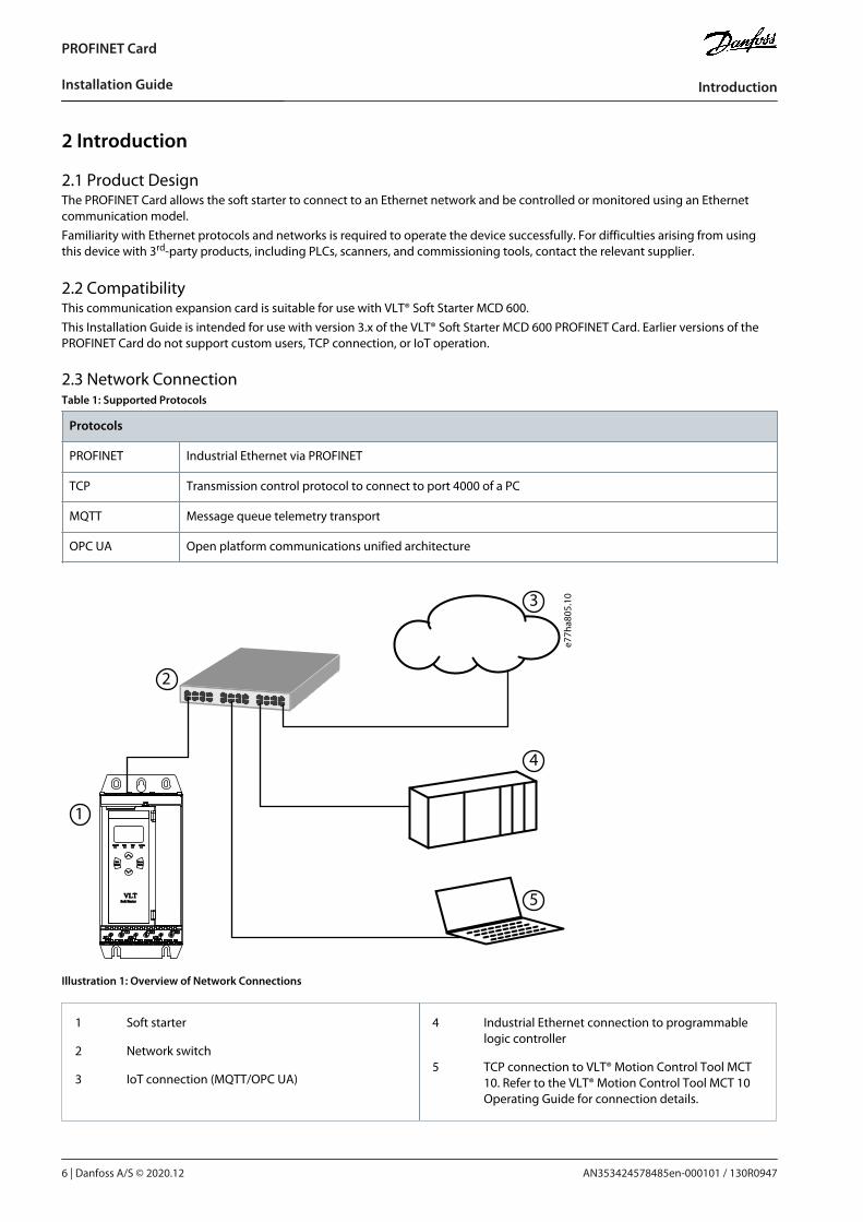
Illustration 1: Overview of Network Connections
1 Soft starter
2 Network switch
3 IoT connection (MQTT/OPC UA)
4 Industrial Ethernet connection to programmablelogic controller
5 TCP connection to VLT® Motion Control Tool MCT10. Refer to the VLT® Motion Control Tool MCT 10Operating Guide for connection details.
AN353424578485en-000101 / 130R09476 | Danfoss A/S © 2020.12
Introduction
PROFINET Card
Installation Guide
1.
2.
•
•
•
•
•
•
3 Installation
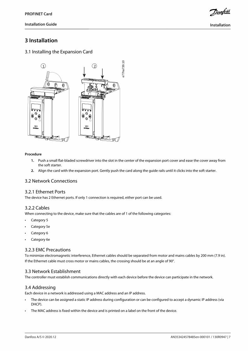
3.1 Installing the Expansion Card
1 2
e77h
a739
.10
Procedure
Push a small flat-bladed screwdriver into the slot in the center of the expansion port cover and ease the cover away fromthe soft starter.Align the card with the expansion port. Gently push the card along the guide rails until it clicks into the soft starter.
3.2 Network Connections
3.2.1 Ethernet PortsThe device has 2 Ethernet ports. If only 1 connection is required, either port can be used.
3.2.2 CablesWhen connecting to the device, make sure that the cables are of 1 of the following categories:
Category 5
Category 5e
Category 6
Category 6e
3.2.3 EMC PrecautionsTo minimize electromagnetic interference, Ethernet cables should be separated from motor and mains cables by 200 mm (7.9 in).If the Ethernet cable must cross motor or mains cables, the crossing should be at an angle of 90°.
3.3 Network EstablishmentThe controller must establish communications directly with each device before the device can participate in the network.
3.4 AddressingEach device in a network is addressed using a MAC address and an IP address.
The device can be assigned a static IP address during configuration or can be configured to accept a dynamic IP address (viaDHCP).
The MAC address is fixed within the device and is printed on a label on the front of the device.
AN353424578485en-000101 / 130R0947 | 7Danfoss A/S © 2020.12
Installation
PROFINET Card
Installation Guide
1.2.
3.
4 Device Configuration
4.1 Configuration of Device NameUse the Ethernet Device Configuration Tool to configure the device. The tool can be downloaded from www.danfoss.com underService and support/Downloads.
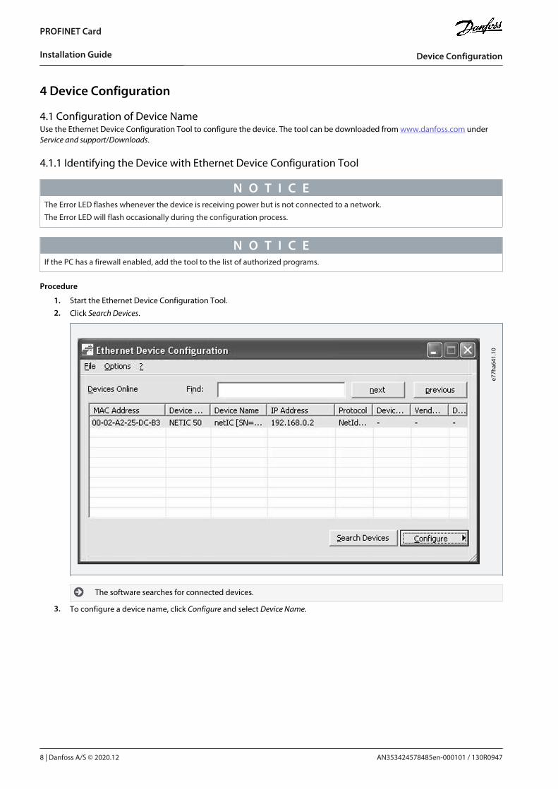
4.1.1 Identifying the Device with Ethernet Device Configuration Tool
N O T I C EThe Error LED flashes whenever the device is receiving power but is not connected to a network.The Error LED will flash occasionally during the configuration process.
N O T I C EIf the PC has a firewall enabled, add the tool to the list of authorized programs.
Procedure
Start the Ethernet Device Configuration Tool.
Click Search Devices.
e77h
a641
.10
The software searches for connected devices.
To configure a device name, click Configure and select Device Name.
AN353424578485en-000101 / 130R09478 | Danfoss A/S © 2020.12
Device Configuration
PROFINET Card
Installation Guide
1.e7
7ha626
.10
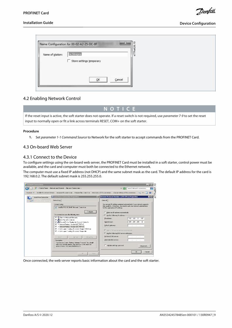
4.2 Enabling Network Control
N O T I C EIf the reset input is active, the soft starter does not operate. If a reset switch is not required, use parameter 7-9 to set the resetinput to normally open or fit a link across terminals RESET, COM+ on the soft starter.
Procedure
Set parameter 1-1 Command Source to Network for the soft starter to accept commands from the PROFINET Card.
4.3 On-board Web Server
4.3.1 Connect to the DeviceTo configure settings using the on-board web server, the PROFINET Card must be installed in a soft starter, control power must beavailable, and the card and computer must both be connected to the Ethernet network.The computer must use a fixed IP address (not DHCP) and the same subnet mask as the card. The default IP address for the card is192.168.0.2. The default subnet mask is 255.255.255.0.
e77h
a807
.10
Once connected, the web server reports basic information about the card and the soft starter.
AN353424578485en-000101 / 130R0947 | 9Danfoss A/S © 2020.12
Device Configuration
PROFINET Card
Installation Guide
•
•
•
--
e77h
a815
.10
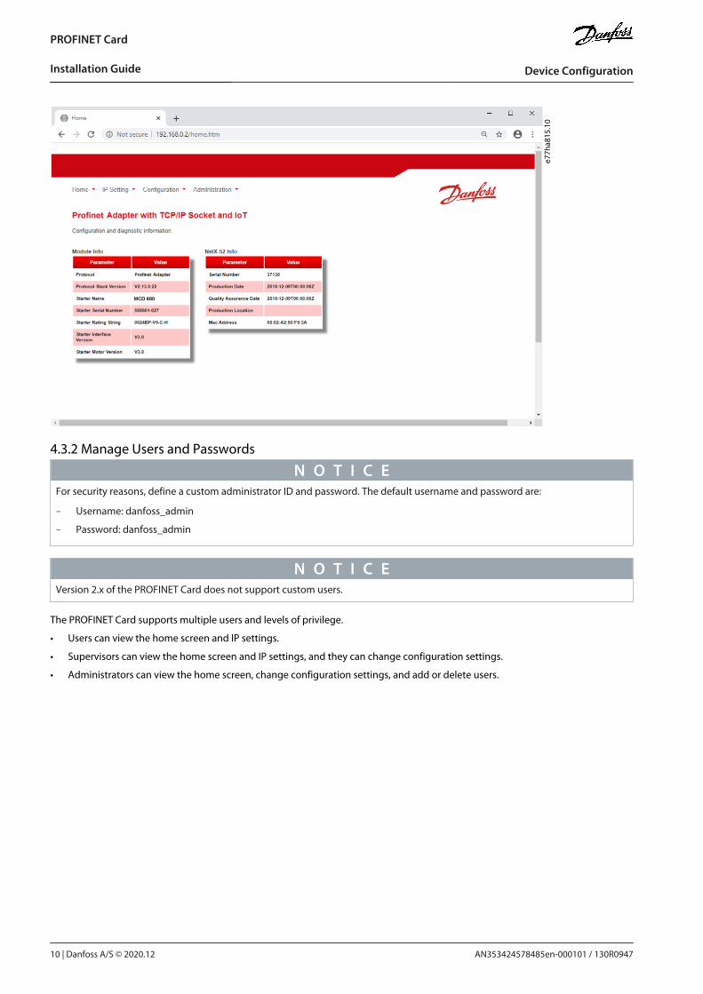
4.3.2 Manage Users and Passwords
N O T I C EFor security reasons, define a custom administrator ID and password. The default username and password are:
Username: danfoss_admin
Password: danfoss_admin
N O T I C EVersion 2.x of the PROFINET Card does not support custom users.
The PROFINET Card supports multiple users and levels of privilege.
Users can view the home screen and IP settings.
Supervisors can view the home screen and IP settings, and they can change configuration settings.
Administrators can view the home screen, change configuration settings, and add or delete users.
AN353424578485en-000101 / 130R094710 | Danfoss A/S © 2020.12
Device Configuration
PROFINET Card
Installation Guide
1.2.3.4.5.6.
1.2.3.
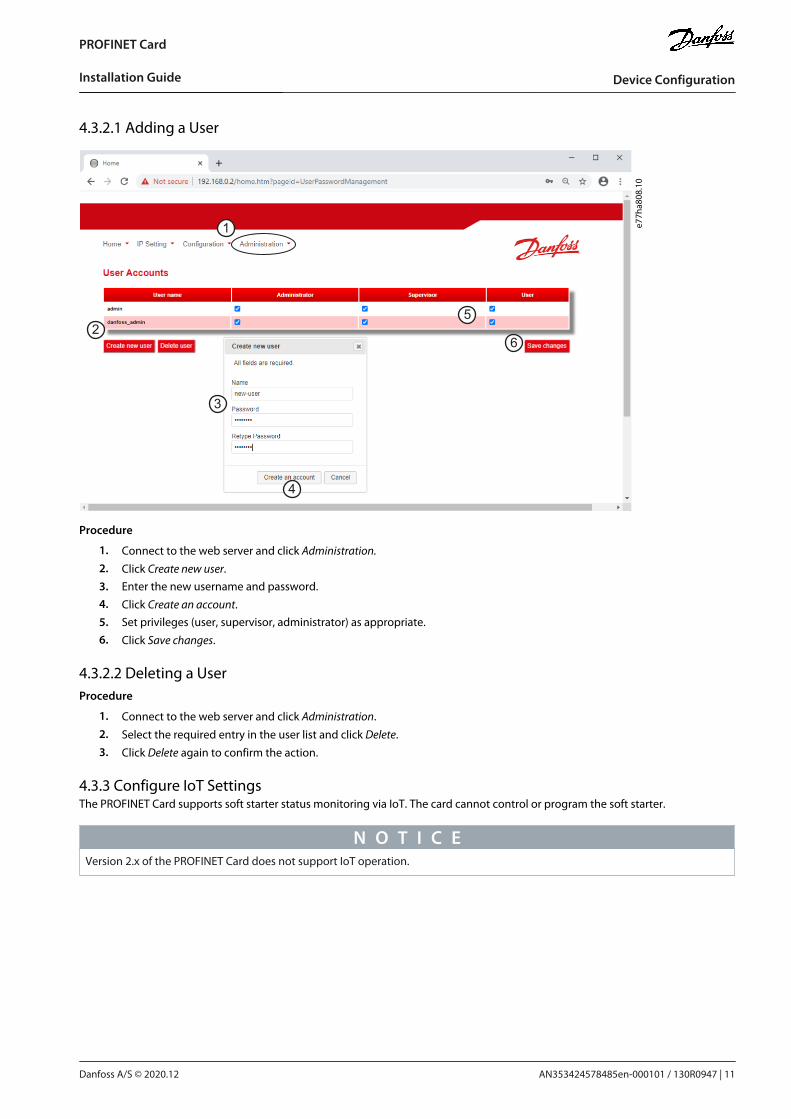
4.3.2.1 Adding a User
1
2
3
5
6
e77h
a808
.10
4
Procedure
Connect to the web server and click Administration.
Click Create new user.Enter the new username and password.
Click Create an account.Set privileges (user, supervisor, administrator) as appropriate.
Click Save changes.
4.3.2.2 Deleting a UserProcedure
Connect to the web server and click Administration.
Select the required entry in the user list and click Delete.
Click Delete again to confirm the action.
4.3.3 Configure IoT SettingsThe PROFINET Card supports soft starter status monitoring via IoT. The card cannot control or program the soft starter.
N O T I C EVersion 2.x of the PROFINET Card does not support IoT operation.
AN353424578485en-000101 / 130R0947 | 11Danfoss A/S © 2020.12
Device Configuration
PROFINET Card
Installation Guide
1.2.3.
4.5.6.
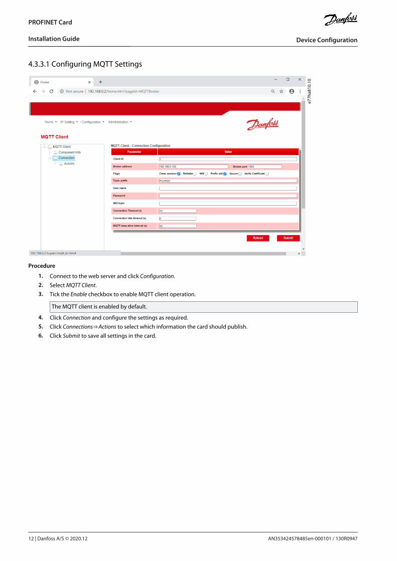
4.3.3.1 Configuring MQTT Settings
e77h
a810
.10
Procedure
Connect to the web server and click Configuration.
Select MQTT Client.
Tick the Enable checkbox to enable MQTT client operation.
The MQTT client is enabled by default.
Click Connection and configure the settings as required.
Click Connections⇒Actions to select which information the card should publish.
Click Submit to save all settings in the card.
AN353424578485en-000101 / 130R094712 | Danfoss A/S © 2020.12
Device Configuration
PROFINET Card
Installation Guide
1.2.3.
4.5.6.
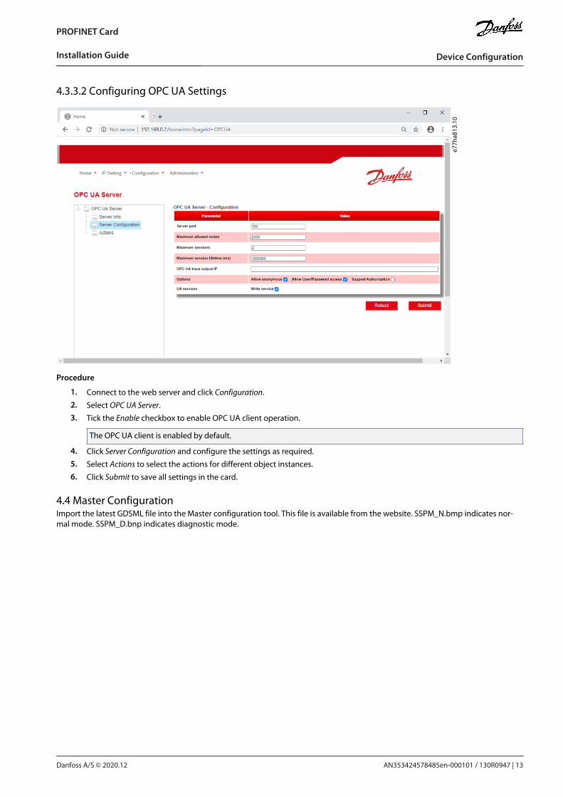
4.3.3.2 Configuring OPC UA Settings
e77h
a813
.10
Procedure
Connect to the web server and click Configuration.
Select OPC UA Server.
Tick the Enable checkbox to enable OPC UA client operation.
The OPC UA client is enabled by default.
Click Server Configuration and configure the settings as required.
Select Actions to select the actions for different object instances.
Click Submit to save all settings in the card.
4.4 Master ConfigurationImport the latest GDSML file into the Master configuration tool. This file is available from the website. SSPM_N.bmp indicates nor-mal mode. SSPM_D.bnp indicates diagnostic mode.
AN353424578485en-000101 / 130R0947 | 13Danfoss A/S © 2020.12
Device Configuration
PROFINET Card
Installation Guide
5 Operation
5.1 Requirements for Successful OperationThe device has been designed for use in a system complying with the PROFINET standard. For successful operation, the controllermust also support all functions and interfaces described in this manual.
5.2 Device ClassificationThe PROFINET Card is a PROFINET I/O-device and must be managed by an I/O-controller over Ethernet.
5.3 Ensuring Safe and Successful ControlData written to the device remains in its registers until the data is overwritten or the device is reinitialized. If the soft starter is con-trolled via parameter 7-1 Command Override or is disabled via the reset input (terminals RESET, COM+), fieldbus commands shouldbe cleared from the registers. If a command is not cleared, it is re-sent to the soft starter once fieldbus control resumes.
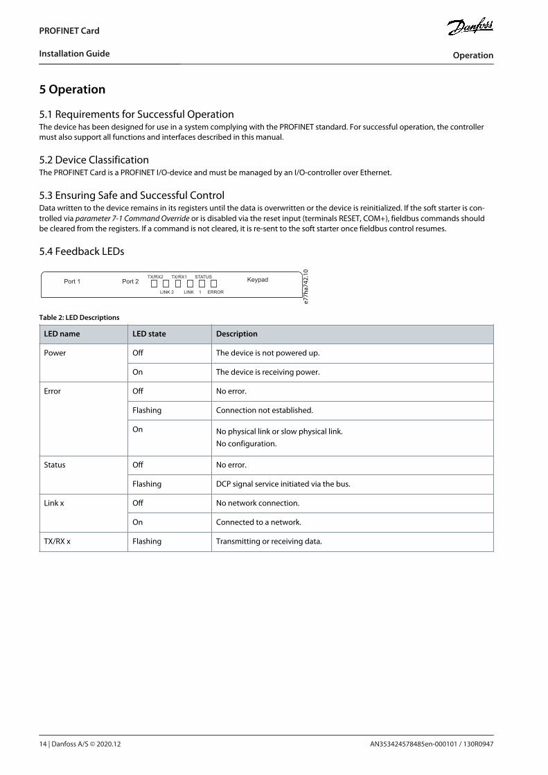
5.4 Feedback LEDs
Port 1 Port 2 Keypad
LINK 2
TX/RX2
LINK 1
TX/RX1
ERROR
STATUS
e77h
a742
.10
Table 2: LED Descriptions
LED name LED state Description
Power Off The device is not powered up.
On The device is receiving power.
Error Off No error.
Flashing Connection not established.
On No physical link or slow physical link.No configuration.
Status Off No error.
Flashing DCP signal service initiated via the bus.
Link x Off No network connection.
On Connected to a network.
TX/RX x Flashing Transmitting or receiving data.
AN353424578485en-000101 / 130R094714 | Danfoss A/S © 2020.12
Operation
PROFINET Card
Installation Guide
6 Packet Structures
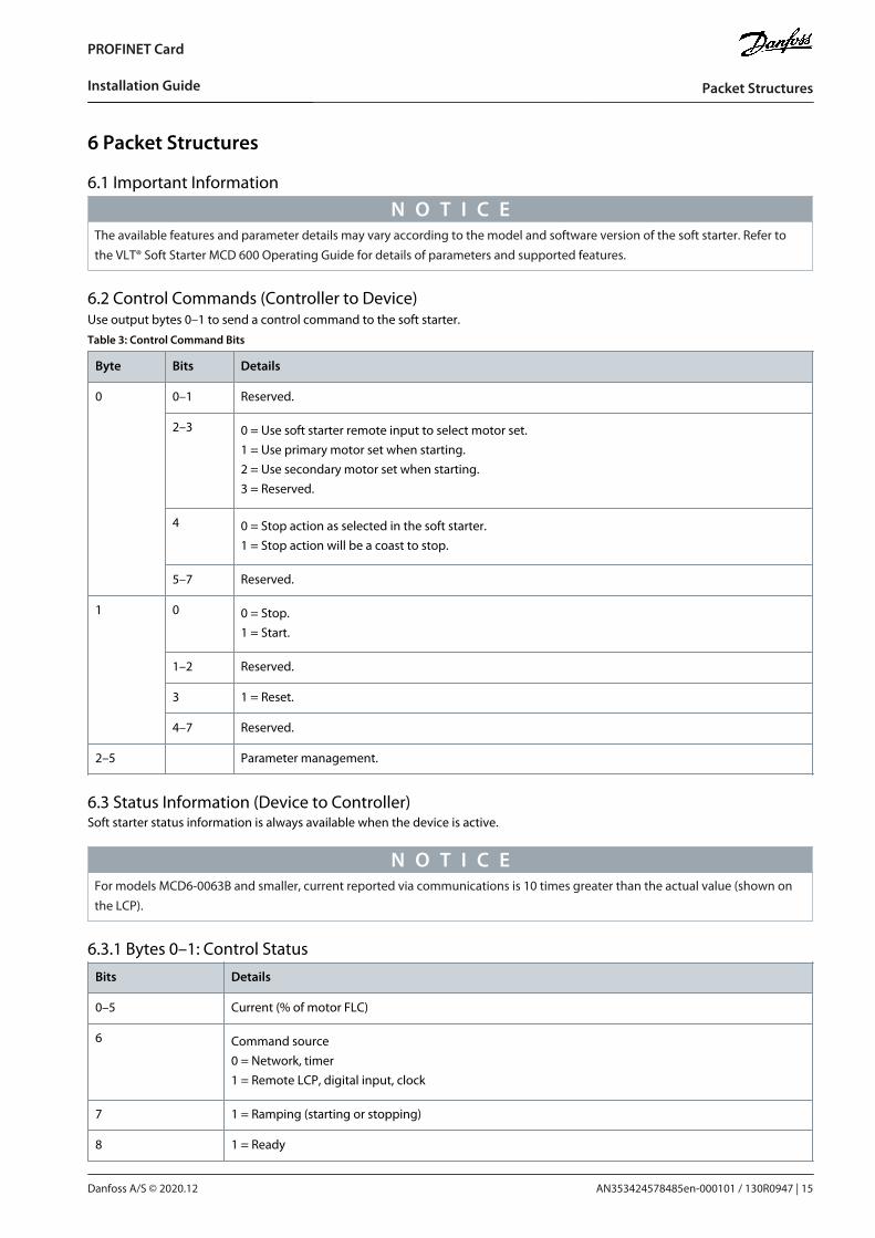
6.1 Important Information
N O T I C EThe available features and parameter details may vary according to the model and software version of the soft starter. Refer tothe VLT® Soft Starter MCD 600 Operating Guide for details of parameters and supported features.
6.2 Control Commands (Controller to Device)Use output bytes 0–1 to send a control command to the soft starter.Table 3: Control Command Bits
Byte Bits Details
0 0–1 Reserved.
2–3 0 = Use soft starter remote input to select motor set.1 = Use primary motor set when starting.2 = Use secondary motor set when starting.3 = Reserved.
4 0 = Stop action as selected in the soft starter.1 = Stop action will be a coast to stop.
5–7 Reserved.
1 0 0 = Stop.1 = Start.
1–2 Reserved.
3 1 = Reset.
4–7 Reserved.
2–5 Parameter management.
6.3 Status Information (Device to Controller)Soft starter status information is always available when the device is active.
N O T I C EFor models MCD6-0063B and smaller, current reported via communications is 10 times greater than the actual value (shown onthe LCP).
6.3.1 Bytes 0–1: Control Status
Bits Details
0–5 Current (% of motor FLC)
6 Command source0 = Network, timer1 = Remote LCP, digital input, clock
7 1 = Ramping (starting or stopping)
8 1 = Ready
AN353424578485en-000101 / 130R0947 | 15Danfoss A/S © 2020.12
Packet Structures
PROFINET Card
Installation Guide
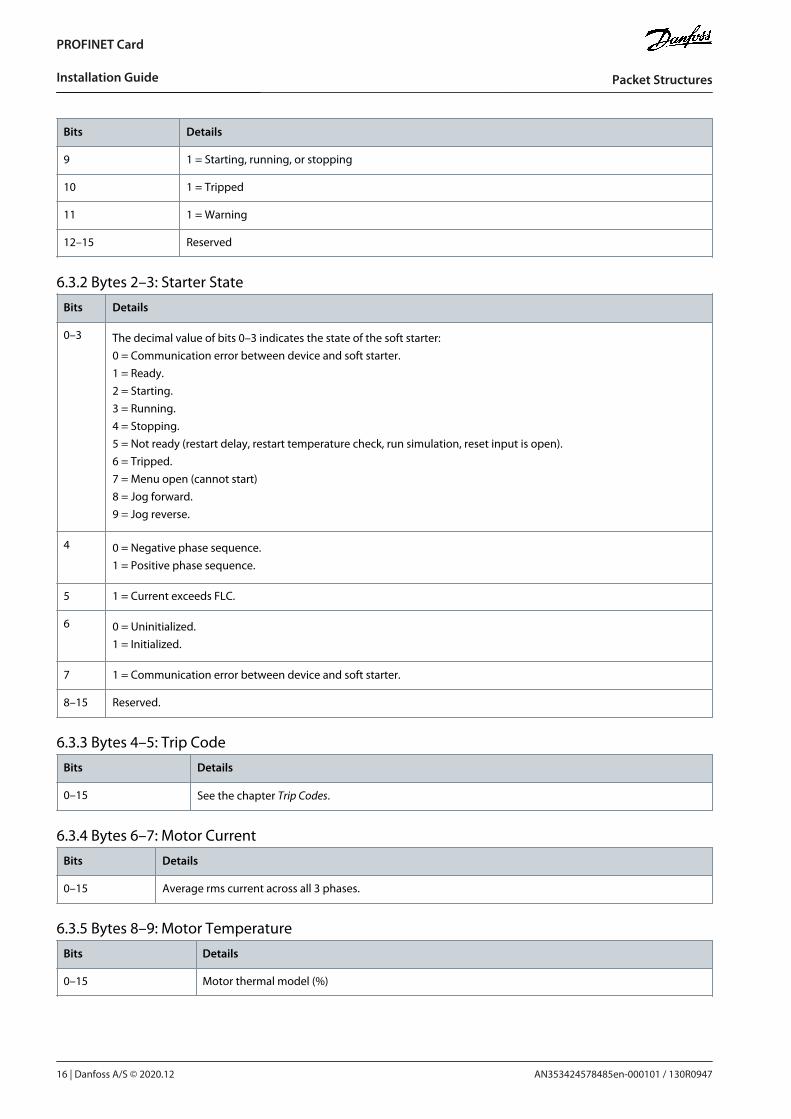
Bits Details
9 1 = Starting, running, or stopping
10 1 = Tripped
11 1 = Warning
12–15 Reserved
6.3.2 Bytes 2–3: Starter State
Bits Details
0–3 The decimal value of bits 0–3 indicates the state of the soft starter:0 = Communication error between device and soft starter.1 = Ready.2 = Starting.3 = Running.4 = Stopping.5 = Not ready (restart delay, restart temperature check, run simulation, reset input is open).6 = Tripped.7 = Menu open (cannot start)8 = Jog forward.9 = Jog reverse.
4 0 = Negative phase sequence.1 = Positive phase sequence.
5 1 = Current exceeds FLC.
6 0 = Uninitialized.1 = Initialized.
7 1 = Communication error between device and soft starter.
8–15 Reserved.
6.3.3 Bytes 4–5: Trip Code
Bits Details
0–15 See the chapter Trip Codes.
6.3.4 Bytes 6–7: Motor Current
Bits Details
0–15 Average rms current across all 3 phases.
6.3.5 Bytes 8–9: Motor Temperature
Bits Details
0–15 Motor thermal model (%)
AN353424578485en-000101 / 130R094716 | Danfoss A/S © 2020.12
Packet Structures
PROFINET Card
Installation Guide
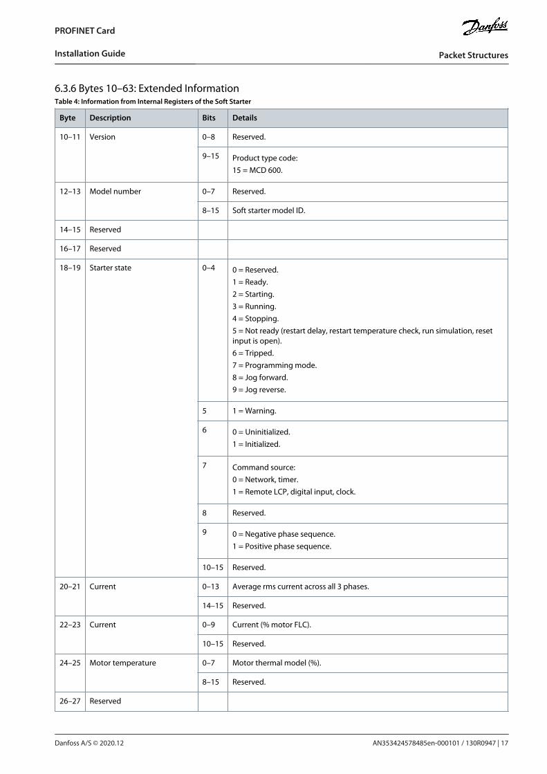
6.3.6 Bytes 10–63: Extended InformationTable 4: Information from Internal Registers of the Soft Starter
Byte Description Bits Details
10–11 Version 0–8 Reserved.
9–15 Product type code:15 = MCD 600.
12–13 Model number 0–7 Reserved.
8–15 Soft starter model ID.
14–15 Reserved
16–17 Reserved
18–19 Starter state 0–4 0 = Reserved.1 = Ready.2 = Starting.3 = Running.4 = Stopping.5 = Not ready (restart delay, restart temperature check, run simulation, resetinput is open).6 = Tripped.7 = Programming mode.8 = Jog forward.9 = Jog reverse.
5 1 = Warning.
6 0 = Uninitialized.1 = Initialized.
7 Command source:0 = Network, timer.1 = Remote LCP, digital input, clock.
8 Reserved.
9 0 = Negative phase sequence.1 = Positive phase sequence.
10–15 Reserved.
20–21 Current 0–13 Average rms current across all 3 phases.
14–15 Reserved.
22–23 Current 0–9 Current (% motor FLC).
10–15 Reserved.
24–25 Motor temperature 0–7 Motor thermal model (%).
8–15 Reserved.
26–27 Reserved
AN353424578485en-000101 / 130R0947 | 17Danfoss A/S © 2020.12
Packet Structures
PROFINET Card
Installation Guide
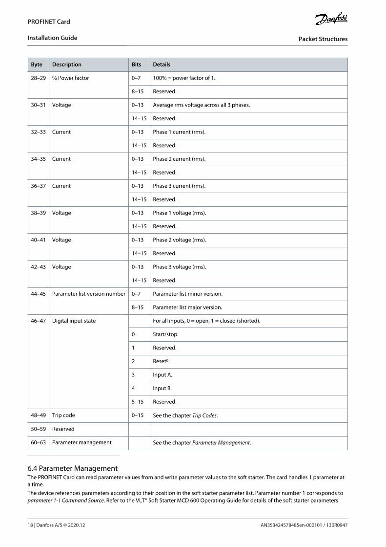
Byte Description Bits Details
28–29 % Power factor 0–7 100% = power factor of 1.
8–15 Reserved.
30–31 Voltage 0–13 Average rms voltage across all 3 phases.
14–15 Reserved.
32–33 Current 0–13 Phase 1 current (rms).
14–15 Reserved.
34–35 Current 0–13 Phase 2 current (rms).
14–15 Reserved.
36–37 Current 0–13 Phase 3 current (rms).
14–15 Reserved.
38–39 Voltage 0–13 Phase 1 voltage (rms).
14–15 Reserved.
40–41 Voltage 0–13 Phase 2 voltage (rms).
14–15 Reserved.
42–43 Voltage 0–13 Phase 3 voltage (rms).
14–15 Reserved.
44–45 Parameter list version number 0–7 Parameter list minor version.
8–15 Parameter list major version.
46–47 Digital input state For all inputs, 0 = open, 1 = closed (shorted).
0 Start/stop.
1 Reserved.
2 Reset().
3 Input A.
4 Input B.
5–15 Reserved.
48–49 Trip code 0–15 See the chapter Trip Codes.
50–59 Reserved
60–63 Parameter management See the chapter Parameter Management.
6.4 Parameter ManagementThe PROFINET Card can read parameter values from and write parameter values to the soft starter. The card handles 1 parameter ata time.The device references parameters according to their position in the soft starter parameter list. Parameter number 1 corresponds toparameter 1-1 Command Source. Refer to the VLT® Soft Starter MCD 600 Operating Guide for details of the soft starter parameters.
AN353424578485en-000101 / 130R094718 | Danfoss A/S © 2020.12
Packet Structures
PROFINET Card
Installation Guide
-
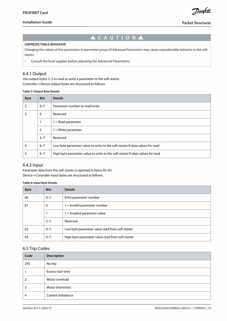
C A U T I O NUNPREDICTABLE BEHAVIOR
Changing the values of the parameters in parameter group 20 Advanced Parameters may cause unpredictable behavior in the softstarter.
Consult the local supplier before adjusting the Advanced Parameters.
6.4.1 OutputUse output bytes 2–5 to read or write a parameter to the soft starter.Controller⇒Device output bytes are structured as follows:
Table 5: Output Byte Details
Byte Bits Details
2 0–7 Parameter number to read/write
3 0 Reserved
1 1 = Read parameter
2 1 = Write parameter
3–7 Reserved
4 0–7 Low byte parameter value to write to the soft starter/0 data values for read
5 0–7 High byte parameter value to write to the soft starter/0 data values for read
6.4.2 InputParameter data from the soft starter is reported in bytes 60–63.Device⇒Controller input bytes are structured as follows.
Table 6: Input Byte Details
Byte Bits Details
60 0–7 Echo parameter number
61 0 1 = Invalid parameter number
1 1 = Invalied parameter value
2–7 Reserved
62 0–7 Low byte parameter value read from soft starter
63 0–7 High byte parameter value read from soft starter
6.5 Trip Codes
Code Description
255 No trip
1 Excess start time
2 Motor overload
3 Motor thermistor
4 Current imbalance
AN353424578485en-000101 / 130R0947 | 19Danfoss A/S © 2020.12
Packet Structures
PROFINET Card
Installation Guide
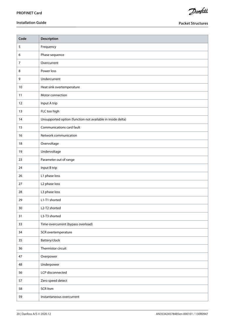
Code Description
5 Frequency
6 Phase sequence
7 Overcurrent
8 Power loss
9 Undercurrent
10 Heat sink overtemperature
11 Motor connection
12 Input A trip
13 FLC too high
14 Unsupported option (function not available in inside delta)
15 Communications card fault
16 Network communication
18 Overvoltage
19 Undervoltage
23 Parameter out of range
24 Input B trip
26 L1 phase loss
27 L2 phase loss
28 L3 phase loss
29 L1-T1 shorted
30 L2-T2 shorted
31 L3-T3 shorted
33 Time-overcurrent (bypass overload)
34 SCR overtemperature
35 Battery/clock
36 Thermistor circuit
47 Overpower
48 Underpower
56 LCP disconnected
57 Zero speed detect
58 SCR Itsm
59 Instantaneous overcurrent
AN353424578485en-000101 / 130R094720 | Danfoss A/S © 2020.12
Packet Structures
PROFINET Card
Installation Guide
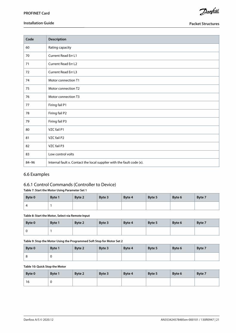
Code Description
60 Rating capacity
70 Current Read Err L1
71 Current Read Err L2
72 Current Read Err L3
74 Motor connection T1
75 Motor connection T2
76 Motor connection T3
77 Firing fail P1
78 Firing fail P2
79 Firing fail P3
80 VZC fail P1
81 VZC fail P2
82 VZC fail P3
83 Low control volts
84–96 Internal fault x. Contact the local supplier with the fault code (x).
6.6 Examples
6.6.1 Control Commands (Controller to Device)Table 7: Start the Motor Using Parameter Set 1
Byte 0 Byte 1 Byte 2 Byte 3 Byte 4 Byte 5 Byte 6 Byte 7
4 1
Table 8: Start the Motor, Select via Remote Input
Byte 0 Byte 1 Byte 2 Byte 3 Byte 4 Byte 5 Byte 6 Byte 7
0 1
Table 9: Stop the Motor Using the Programmed Soft Stop for Motor Set 2
Byte 0 Byte 1 Byte 2 Byte 3 Byte 4 Byte 5 Byte 6 Byte 7
8 0
Table 10: Quick Stop the Motor
Byte 0 Byte 1 Byte 2 Byte 3 Byte 4 Byte 5 Byte 6 Byte 7
16 0
AN353424578485en-000101 / 130R0947 | 21Danfoss A/S © 2020.12
Packet Structures
PROFINET Card
Installation Guide
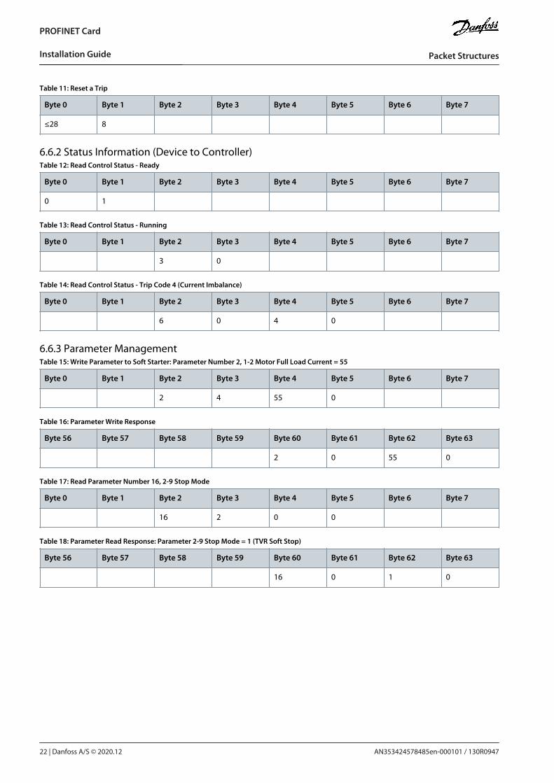
Table 11: Reset a Trip
Byte 0 Byte 1 Byte 2 Byte 3 Byte 4 Byte 5 Byte 6 Byte 7
≤28 8
6.6.2 Status Information (Device to Controller)Table 12: Read Control Status - Ready
Byte 0 Byte 1 Byte 2 Byte 3 Byte 4 Byte 5 Byte 6 Byte 7
0 1
Table 13: Read Control Status - Running
Byte 0 Byte 1 Byte 2 Byte 3 Byte 4 Byte 5 Byte 6 Byte 7
3 0
Table 14: Read Control Status - Trip Code 4 (Current Imbalance)
Byte 0 Byte 1 Byte 2 Byte 3 Byte 4 Byte 5 Byte 6 Byte 7
6 0 4 0
6.6.3 Parameter ManagementTable 15: Write Parameter to Soft Starter: Parameter Number 2, 1-2 Motor Full Load Current = 55
Byte 0 Byte 1 Byte 2 Byte 3 Byte 4 Byte 5 Byte 6 Byte 7
2 4 55 0
Table 16: Parameter Write Response
Byte 56 Byte 57 Byte 58 Byte 59 Byte 60 Byte 61 Byte 62 Byte 63
2 0 55 0
Table 17: Read Parameter Number 16, 2-9 Stop Mode
Byte 0 Byte 1 Byte 2 Byte 3 Byte 4 Byte 5 Byte 6 Byte 7
16 2 0 0
Table 18: Parameter Read Response: Parameter 2-9 Stop Mode = 1 (TVR Soft Stop)
Byte 56 Byte 57 Byte 58 Byte 59 Byte 60 Byte 61 Byte 62 Byte 63
16 0 1 0
AN353424578485en-000101 / 130R094722 | Danfoss A/S © 2020.12
Packet Structures
PROFINET Card
Installation Guide
7 Network Design
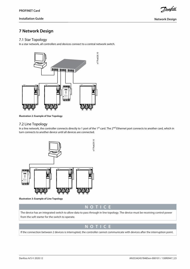
7.1 Star TopologyIn a star network, all controllers and devices connect to a central network switch.
e77h
a628
.10
Illustration 2: Example of Star Topology
7.2 Line TopologyIn a line network, the controller connects directly to 1 port of the 1st card. The 2nd Ethernet port connects to another card, which inturn connects to another device until all devices are connected.
e77h
a629
.10
Illustration 3: Example of Line Topology
N O T I C EThe device has an integrated switch to allow data to pass through in line topology. The device must be receiving control powerfrom the soft starter for the switch to operate.
N O T I C EIf the connection between 2 devices is interrupted, the controller cannot communicate with devices after the interruption point.
AN353424578485en-000101 / 130R0947 | 23Danfoss A/S © 2020.12
Network Design
PROFINET Card
Installation Guide
N O T I C EEach connection adds a delay to the communication with the next device. The maximum number of devices in a line network is32. Exceeding this number may reduce the reliability of the network.
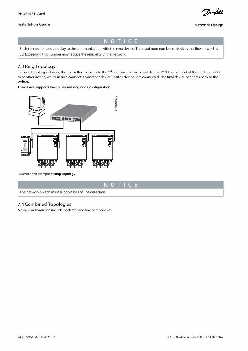
7.3 Ring TopologyIn a ring topology network, the controller connects to the 1st card via a network switch. The 2nd Ethernet port of the card connectsto another device, which in turn connects to another device until all devices are connected. The final device connects back to theswitch.The device supports beacon-based ring node configuration.
e77h
a630
.10
Illustration 4: Example of Ring Topology
N O T I C EThe network switch must support loss of line detection.
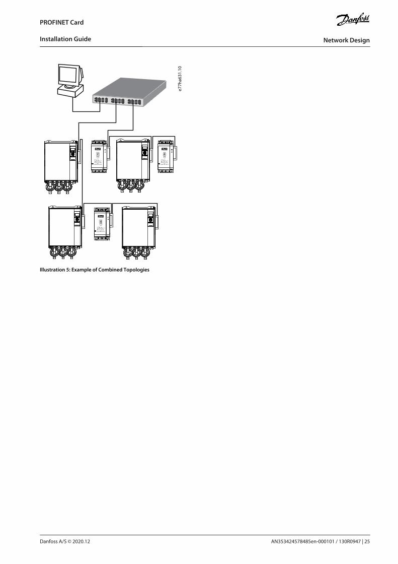
7.4 Combined TopologiesA single network can include both star and line components.
AN353424578485en-000101 / 130R094724 | Danfoss A/S © 2020.12
Network Design
PROFINET Card
Installation Guide
e77h
a631
.10
Illustration 5: Example of Combined Topologies
AN353424578485en-000101 / 130R0947 | 25Danfoss A/S © 2020.12
Network Design
PROFINET Card
Installation Guide
8 Specifications
8.1 ConnectionsSoft starter 16-way pin assembly
Contacts Gold flash
Network RJ45
8.2 SettingsIP address Automatically assigned
Device name Automatically assigned, configurable
8.3 NetworkLink speed 10 Mbps, 100 Mbps (auto-detect)
Full duplex
Auto crossover
8.4 PowerConsumption (steady state, maximum) 35 mA@24 V DC
Reverse polarity protected
Galvanically isolated
8.5 CertificationRCM IEC 60947-4-2
CE EN 60947-4-2
PROFIBUS & PROFINET International
AN353424578485en-000101 / 130R094726 | Danfoss A/S © 2020.12
Specifications
PROFINET Card
Installation Guide

AN353424578485en-000101 / 130R0947 | 27Danfoss A/S © 2020.12
Specifications
PROFINET Card
Installation Guide

AN353424578485en-000101 / 130R0947
*M0025701*Danfoss A/S © 2020.12
Danfoss A/SUlsnaes 1DK-6300 Graastenvlt-drives.danfoss.com
Danfoss can accept no responsibility for possible errors in catalogs, brochures and other printed material. Danfoss reserves the right to alter its products without notice. Thisalso applies to products already on order provided that such alterations can be made without subsequential changes being necessary in specifications already agreed. Alltrademarks in this material are property of the respective companies. Danfoss and the Danfoss logotype are trademarks of Danfoss A/S. All rights reserved.
*130R0947*